Article

Amplitude Dependent Internal Friction in a Mg-Al-Zn Alloy Studied after Thermal and Mechanical Treatment

1
Department of Physics of Materials, Faculty of Mathematics and Physics, Charles University, Ke Karlovu 5, 121 16 Praha 2, Czech Republic
2
COMTES FHT, Průmyslová 996, 334 41 Dobřany, Czech Republic
*
Author to whom correspondence should be addressed.
Metals 2017, 7(10), 433; https://doi.org/10.3390/met7100433
Submission received: 11 July 2017 / Revised: 3 October 2017 / Accepted: 12 October 2017 / Published: 17 October 2017

Abstract

:
The amplitude-dependent internal friction of continuously-cast and rolled AZ31 magnesium alloy was measured in this study. Samples were annealed and quenched step by step; immediately after the treatment, the amplitude dependence of the logarithmic decrement was measured. Changes in the microstructure due to thermomechanical treatment were reflected in changes in the damping. Internal friction is influenced by the dislocation substructure and its modification due to solute atoms migration, microplastic deformation, and twins’ formation. Internal friction in the rolled sheets is affected by the rolling texture.

1. Introduction

The amplitude-dependent internal friction (ADIF) is usually explained by the Granato and Lücke model (G-L model). This model in its original form, published in the 1950s [1,2], was constructed for “pure“ metals loaded at very low temperatures; for movable dislocations in the slip plane and their break-away from the static pinning points (usually solute atoms, point defects or their small clusters). Later, the G-L model was customized several times with the aim to express further aspects of this process, such as the thermally-activated break-away of dislocations, dragging of solute atoms by the dislocation segments or diffusive movement of solute atoms at elevated temperatures [3,4,5,6,7,8,9]. It is interesting to note the idea by Gremaud who applied the Brownian motion of overdamped dislocations jumping over localized obstacles distributed on the dislocation glide plane for an explanation of the interaction with point defects [10]. Authors of many papers concerning ADIF usually apply the original G-L model in the simplest form and, also, in the case of concentrated alloys [11], sometimes this model is not applicable. This depends on the material microstructure, mobility of solute atoms, their distribution (isolated solute atoms, their small clusters, precipitates, particles of the second phase). The microstructure may be changed by thermal and mechanical treatments [12,13] and, conversely, such changes must be reflected by the internal friction behaviour. Magnesium alloys of the AZ series (Mg-Al-Zn) are mostly used for industrial applications. With increasing Al content, the strength of the alloys increase, while lower Al content is favourable for material plasticity. AZ31 magnesium alloy is in the focus of design engineers. Data concerning the ADIF of magnesium alloys of the AZ series were reported in a number of papers [14,15,16,17,18]. Authors tried to find the link between damping behaviour and the alloy’s microstructure and its changes. Note that these attempts did not give a comprehensive view of this problem. The main goal of this study was applying the ADIF to investigate the microstructure and its evolution in the cast and rolled AZ31 magnesium alloy after thermal and mechanical treatments with the aim to elucidate the details of microstructure changes.

2. Materials and Methods

Magnesium alloy AZ31 (nominal composition Mg-3Al-1Zn) was used in two structural states: as the continuously-cast alloy (AZ31_CC) and conventionally-rolled sheets (AZ31_RS). The chemical composition of both materials is introduced in Table 1. The microstructure of the continuously-cast alloy was refined using a master alloy containing about 20 vol % SiC particles [19,20]. The master alloy was prepared using SiC micro-powder (particle size of 2 µm) and AZ31 alloy powder with a median particle size of 20 µm. Both powders were mixed and milled together for 12 h in a planetary mill in a protective argon atmosphere. The mixture was then compacted and hot extruded in a horizontal extrusion press. The AZ31 alloy was continuously cast together with small chunks of the master alloy that were preheated and dissolved on a casting spoon just below the surface of the melt. The melt was stirred gently for a homogenous distribution of the dissolving master alloy throughout the melt. SiC particles were not detected in the casting; they were mostly dissolved in the alloy. The resulting Si content in the alloy was 0.06 wt %. Commercially-available sheets were used as a severely deformed AZ31 alloy. The sheets were manufactured by Kalbin Metals Co (Tianjin, China). The samples for the damping measurements were machined from the ingot and sheet as cantilever beams (80 mm long, 10 mm wide and with a thickness of 3 mm (AZ31_CC) and 2.3 mm (AZ31_RS), respectively). Samples from the rolled sheet were cut so that the longest sample axis was either parallel (L) or perpendicular to the rolling direction (T).
Amplitude-dependent internal friction was measured as the damping of the free vibrations in a bending mode. The logarithmic decrement, δ, was estimated according to the following equation:
A(t) = A0 exp(−δt/TP)
where A is the amplitude of free vibrations, t is the time, and TP is the period of the vibrations. Two different measurement setups were used:
  • Electromagnetic excitation and recording of vibrations—the principle is described in [21]. The resonant frequency was ~40 Hz.
  • Manual excitation and record of vibrations by a laser. The resonant frequency was 14 Hz. Manual excitation was used for AZ31 sheets.
Special software was used to evaluate the logarithmic decrement. The amplitude dependences were measured at decreasing amplitude from its maximum value.
The microstructure of the samples was studied using an Olympus light microscope (Olympus, Tokyo, Japan), the details of the phases were analysed by a Tescan Vega LMU II scanning electron microscope (TESCAN ORSAY HOLDING, Brno, Czech Republic), the texture of the rolled sheet was determined using an PANalytical XPert MRD X-ray diffractometer using CuKα radiation (PANanalytical, Almelo, The Netherlands).
Cast samples were annealed at selected temperatures ranging from 20 to 400 °C and then quenched in room temperature water. The temperature step was 20 °C and the annealing time was 20 min. The decrement was measured at room temperature after quenching. Rolled samples were heat treated with a heating rate of 0.9 K/min up to 400 °C, then cooling to room temperature. Some samples were pre-strained in tension for 1% of plastic deformation.

3. Experimental Results

A light micrograph of the AZ31_CC sample is introduced in Figure 1a. Although the content of both the main alloying elements is below the solubility limit, SEM line spectroscopy showed small Mg17Al12 precipitates together with Mn and Si (dark) particles, as can be seen from the scanning electron micrograph in Figure 1b. The grain size was estimated to be 190 ± 30 μm. AZ31 alloy prepared with the same technology without any refiner exhibited a grain size of 620 ± 40 μm [20]. The grain size was measured by the average linear intercept method.
The microstructure of the AZ31 rolled sheet is shown in Figure 2a. The grain structure of the sheet is finer compared with the continuously-cast material. The grain size was estimated to be 32 ± 7 μm. Many twins are visible in the AZ31 sheet microstructure as demonstrated in Figure 2a. The AZ31 rolled sheet exhibited a fibre texture typical for rolled magnesium materials. Basal planes (0001) are mostly parallel to the sheet surface (see Figure 2b).
Figure 3a–c shows the plots of the logarithmic decrement against the logarithm of the strain amplitude for AZ31 CC. Temperatures in Figure 3 indicate the upper temperatures of the quenching cycle. For a clearer arrangement, only the amplitude dependences for selected temperatures is shown in Figure 3. It is evident that the logarithmic decrement for lower amplitudes is amplitude-independent. Achieving some critical amplitude εcr the decrement increases with increasing amplitude. Thus, the decrement may be divided into two components:
δ = δ0 + δH(ε)
where δ0 is the amplitude-independent component and δH(ε) is the amplitude-dependent component of the decrement.
The amplitude dependences of the decrement introduced in Figure 3a were measured after quenching between room temperature and increasing the upper temperatures up to 200 °C. Quenching has no significant influence on the amplitude dependences of the decrement; the curves are practically identical.
Quenching with the upper temperatures higher than 200 °C causes a substantial decrease of the decrement in the amplitude-dependent part, while the amplitude-independent components are almost not influenced (Figure 3b). The minimum decrement was found after treatment with the upper temperature of 260 °C. Thermal cycling at temperatures higher than 260 °C increased the decrement again in the amplitude-dependent region (Figure 3c). An increase in the decrement achieved the values which were observed on the as-cast material.
Amplitudes, εH, necessary to achieve a certain value of the amplitude dependent damping value, δH, are introduced in Figure 4 depending on the upper temperature of the thermal cycle. The obtained results indicate that main changes in the microstructure took place in the temperature ranges with an upper temperature of the quenching cycle between 200 and 300 °C. The microstructure of the sample after the measurement series is shown in Figure 5. Comparing with the as-prepared state, larger precipitates were partially dissolved. Very small precipitates situated in the grain boundaries are the characteristic feature of the microstructure.
The amplitude dependences of the decrement obtained for rolled samples cut in the longitudinal orientation (L) and the transversal orientation (T) are presented in Figure 6. Different features of both dependences are obvious; the shift of the curve is estimated for the T orientation to lower amplitudes and high damping values. The influence of the heat treatment (controlled heating to 400 °C and cooling) on the ADIF estimated for both sheet orientations is obvious from Figure 6. While the heat treatment significantly increased the decrement in the sample with the L orientation, damping in the sample of the T orientation was influenced only slightly. The effect of heat treatment on the sheet microstructure is shown in Figure 7. Comparing with the original sample microstructure (see Figure 2a), it is obvious that grain coarsening took place. The original grain size increased in the heat-treated sheets up to 65 ± 10 μm. Pre-straining in tension of 1% increased the damping in samples of both orientations, as is clear from Figure 8a,b.

4. Discussion

4.1. Annealing and Quenching of the Cast Alloy

While the amplitude independent component of decrement is influenced by several mechanisms, such as contributions from grain boundaries, dislocations, thermoelastic and magnetic effects, and all other inhomogeneities present in a material, the amplitude-dependent part of the decrement is only due to the presence of dislocations in the alloy. In the G-L model it is considered that dislocation segments with the length l are weakly pinned along the dislocation line by point defects (primarily solute atoms and their small clusters). Vibration of these dislocation segments is damped mainly by interaction with phonons and electrons. When the stress (strain) carried by the sonic or ultrasonic wave reaches its critical value σcr = Eεcr (where E is Young’s modulus), the dislocation segments break-away from the weak pinning points and longer dislocation segments with a length LN ( « LN) operate in the slip plane and damping increases. Occurrence of the hysteresis damping component δH is dependent on the motion of longer dislocation segments. Let us consider the total dislocation density, ρ, and an application of the periodic stress σ = σ0sinωt, then the amplitude dependent component of internal friction may be in the low frequency and high temperature approximation expressed as [4]:
δ H = ρ L N 2 6 ν ω ( 3 π k T 2 U 0 ) 1 / 2 ( 3 σ 0 2 U 0 G ) 1 / 2   exp [ 4 3 U 0 k T ( U 0 G 3 ) 1 / 2 1 σ 0 ]
where G is the shear modulus, σ0 is the amplitude of the applied stress and ω its frequency, ν the dislocation frequency, U0 is the activation energy, k is the Boltzmann constant, and T is the absolute temperature. In Equation (3) the δH component is an exponential function of the applied stress amplitude similar to the original formula by Granato and Lücke [1,2]. Since the stress amplitude is proportional to the strain amplitude, Equation (3) may be rewritten as:
δ = δ 0 + C 1 ε 0 exp ( C 2 / ε 0 )
where ε0 = σ0/E. One example of an experimental curve fitted to Equation (4) is introduced in Figure 9, where very good regression coefficient of 0.998 was found. Three parameters C1, C2, and δ0 were estimated in the fitting procedure. Results of this fitting procedure are reported in Figure 10, Figure 11 and Figure 12. While δ0 components do not practically change depending on the upper temperature of the thermal cycle (see Figure 10), parameters C1 and C2 are influenced by annealing and quenching of the sample.
All damping measurements were performed at room temperature; therefore, we may consider that the activation energy U0 in Equation (3) is nearly constant. During the thermal cycling, the dislocation density and length of shorter dislocation segments can change while other quantities in Equation (3) may be considered in the first approximation to be constant.
For discussion C2 parameter is more suitable because it depends only on the length of shorter dislocation segments. Figure 12 shows the temperature dependence of the C2 parameter. It can be seen that the C2 parameter increases with increasing upper temperature of the thermal cycle reaching its maximum at 240–260 °C. Comparing Equation (3) with Equation (4) it is obvious that the C2 parameter is proportional to −3/2. Thermal cycling at temperatures up to 200 °C very probably does not change the alloy microstructure. A rapid increase of the C2 parameter at temperatures from 240 to 260 °C indicates a significant shortening of dislocation segments. It is also connected with a decrease of the anelastic relaxation strength (see Figure 3b). We may assume that solute atoms present in the material become mobile and they migrate to the dislocation lines where they may find locations with lower position energy. Dislocation lines are occupied with solute atoms and the length of shorter dislocation segments, , rapidly decreases. The stress necessary for the thermal break-away of dislocation loops σT at a finite temperature is given by [4]:
σ T = σ M [ 1 ( k T U 1 ln A ) 2 / 3 ]
with:
A = 2 3 ν ω σ M σ 0 ( k T U 1 ) 2 / 3
σM is the stress necessary for dislocation depinning in a pure mechanical process. It should be mentioned that for a double loop with the loop length 1 and 2 the stress σM is given by:
σ M = 2 F m b ( 1 + 2 )
Here, Fm is the maximum force between the dislocation and a pinning point. U1 = 4/3(Fm3/Φ)1/2, where Φ is a constant. Since all experiments were performed at room temperature we may assume that the quantities A and U1 are, in the first approximation, independent of the thermal treatment. The maximum value of the C2 parameter was found for upper temperatures in the temperature interval 240–260 °C. After cycling to temperatures higher than 340 °C, the dislocation line is saturated with the solute atoms. The stress for the breakaway of dislocations is really very high due to collective pinning of solute atoms [9]. Note that solute atoms are not uniformly distributed in the alloy. At temperatures about 300 °C, small clusters and precipitates start to dissolve and number of free solute atoms increases. A consequence of this collective pinning is that the amplitude-dependent component of the decrement has a very low value. In this case, the solute atoms are very probably dragged and moved together with dislocation segments [8]. The sample microstructure after thermal treatment is more homogenous. The original precipitates were partially dissolved; for complete dissolution of existing precipitates much longer annealing times are necessary [22].
Thermally-cycled samples exhibited significant residual thermal stresses [23]. These thermal stresses may, during measurements, be set to the applied stress amplitude and cause the micro-plastic deformation of the sample. Figure 13 shows the temperature dependence of the thermal expansion coefficient (CTE). It is apparent that the dependence does not correspond to the quasi-harmonic Debye model of the thermal expansion [24]. The non-linear course of the CTE is due to the sample micro-plastic deformation that was really estimated in the dilatometer as a residual strain after the temperature cycle RT–400 °C. Note that the local maximum in the temperature dependence of the thermal expansion coefficient was estimated at temperatures between 200 and 300 °C. Thermal stresses at the upper temperatures of the thermal cycle 280–300 °C achieved the yield stress in the sample and new dislocations are generated. Newly-created dislocations are only lightly pinned and, therefore, significantly contribute to the damping.

4.2. Rolled Alloy

AZ31 sheets exhibit typical rolling texture where basal planes of the hexagonal cells are almost parallel to the sheet surface [25,26]. Such types of the texture have an important consequence for the material anisotropy. Planar anisotropy was observed also in the tensile tests during the pre-staining of samples: the tensile yield stress TYS(L) = 162 MPa in the L orientation differs from the stress estimated in the T orientation TYS(T) = 85 MPa. Dislocations with the Burgers vector of 1 3 < 11 2 ¯ 0 > (so-called <a> dislocation) have in Mg and Mg alloys the lowest Peierls-Nabarro stress and, therefore, they are easily movable in the basal planes. The slip direction is in this case of L orientation parallel to the rolling direction and therefore the Schmid factor has its maximum value. Vibrating dislocation segments and movement of <a> dislocations in basal planes is the main source of internal friction in the L orientation. On the other hand, deformation twinning as a prevailing mechanism may be considered at the beginning of deformation process in the transversal direction [27]. An elastic strain is, in this case, realised with the twinning-detwinning mechanism. Samples during internal friction measurements are loaded in the bending mode, i.e., one half of the sheet thickness is in tension and the second in compression. Both parts are divided by the neutral plane. The situation is schematically illustrated in Figure 14 where orientation of the rolling direction in relation to the hexagonal cell and acting force is depicted. In the textured sample the <c> axis of the hexagonal cell is perpendicular to the sheet surface. Deformation stresses generate { 10 1 ¯ 2 } < 10 1 ¯ 1 > twins [28]. In the following half cycle detwinning takes place and twins are erased. Such twins can be easily formed because the critical resolved shear stress for twins’ formation is about 2–2.8 MPa [29,30]. Note that twinning is a polar mechanism which may be activated when special geometrical conditions are fulfilled [31]. Twinning–detwinning behaviour was also often observed in fatigue experiments [22,32]. Watanabe and co-workers studying the internal friction in textured pure magnesium found twinning as the important damping mechanism [33]. On the other hand, movement of the twin boundaries as a special type of dislocation may not be excluded as an additional source of internal friction.
The influence of heat treatment on the sheet microstructure, reported in Figure 7, showed grain coarsening. High dislocation density, ρ, after intensive plastic deformation was realized in the rolling process in the as-prepared sheet and, during the heat treatment, partially annealed. Stráská and coworkers studying thermal stability of an AZ31 alloy after hot extrusion and ECAP (EX-ECAP) estimated, using positron annihilation spectroscopy, the rapid decrease of the dislocation density after annealing at temperatures of 200–250 °C [34]. Annealing at temperatures higher than 300 °C caused the grain growth. A decrease in the dislocation density caused an increase in the mean free path of dislocations (slip length) and, hence, also the decrement. On the other hand, the twinning mechanism is only slightly influenced by the heat treatment.
It is reasonable to consider that the pre-straining of L sample in tension increases the dislocation density. Newly-created fresh dislocations are not occupied with solute atoms and, therefore, long free dislocation segments can vibrate and contribute to the damping. The decrement is very sensitive to the length of dislocation segments δ0 ~ 4. The longer dislocation segments, , the higher damping. On the other hand, twinning is the main deformation mechanism during the tensile deformation of the T sample. Newly-created twins and twin boundaries contribute to damping. Note that the damping of T sample after tensile deformation is much higher comparing with the L sample. This result indicates that the twin formation and movement of the twin boundary are effective sources of internal friction.

5. Conclusions

Grain-refined cast magnesium alloy AZ31 was quenched into water of ambient temperature with increasing annealing upper temperatures up to 400 °C. Commercially-rolled AZ31 alloy was annealed and pre-strained in tension. The amplitude dependent internal friction was measured at room temperature on both alloys and the following main results were obtained:
  • Microstructure changes in the cast alloy after step by step annealing and quenching are manifested with the effects in the amplitude dependent internal friction.
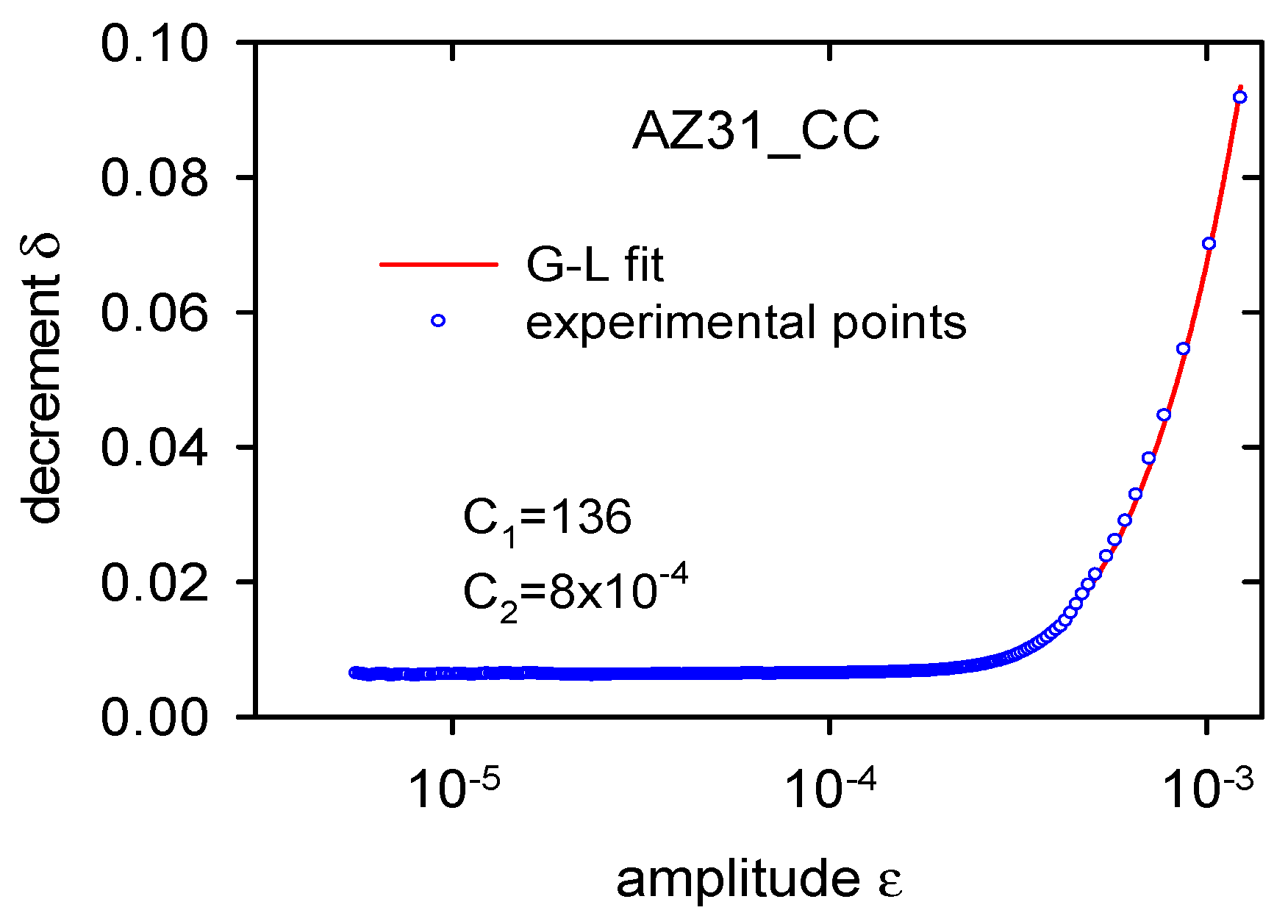
  • The main contribution to the internal friction in the cast alloy is the dislocation internal friction, i.e., vibration of dislocation segments and their thermally-activated movement in the slip plane.
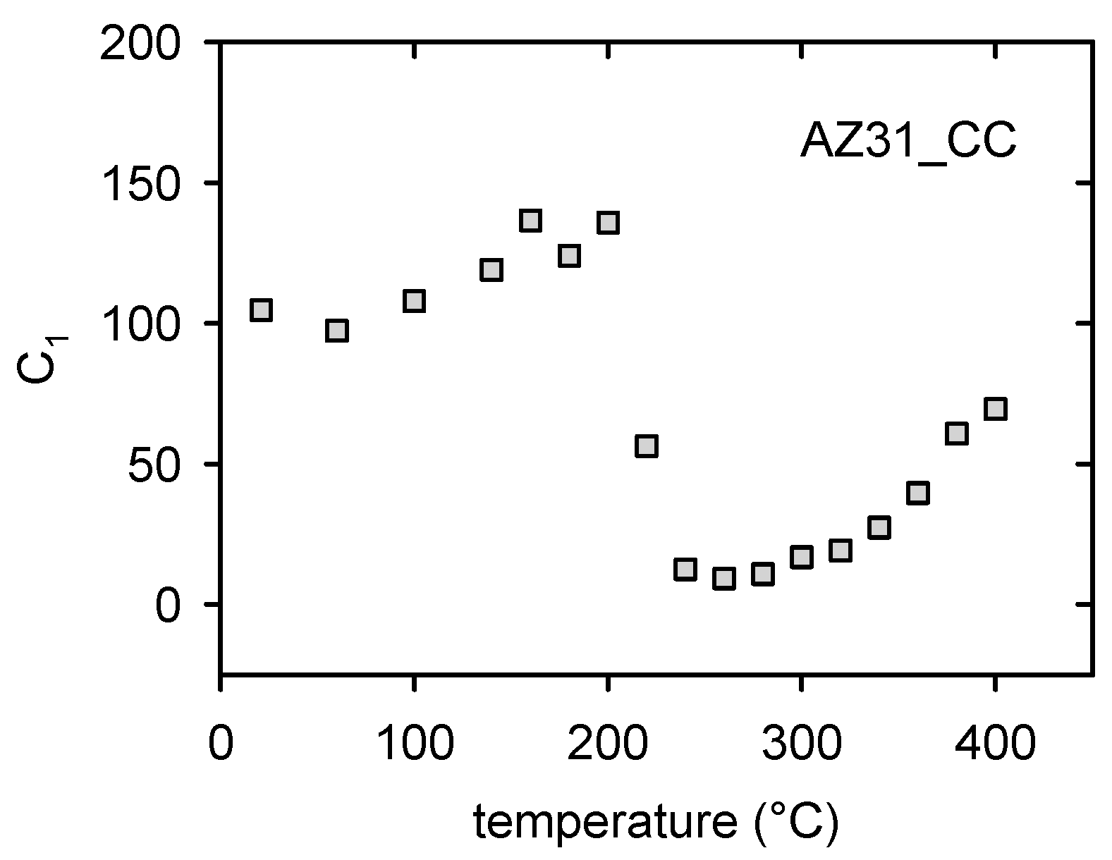
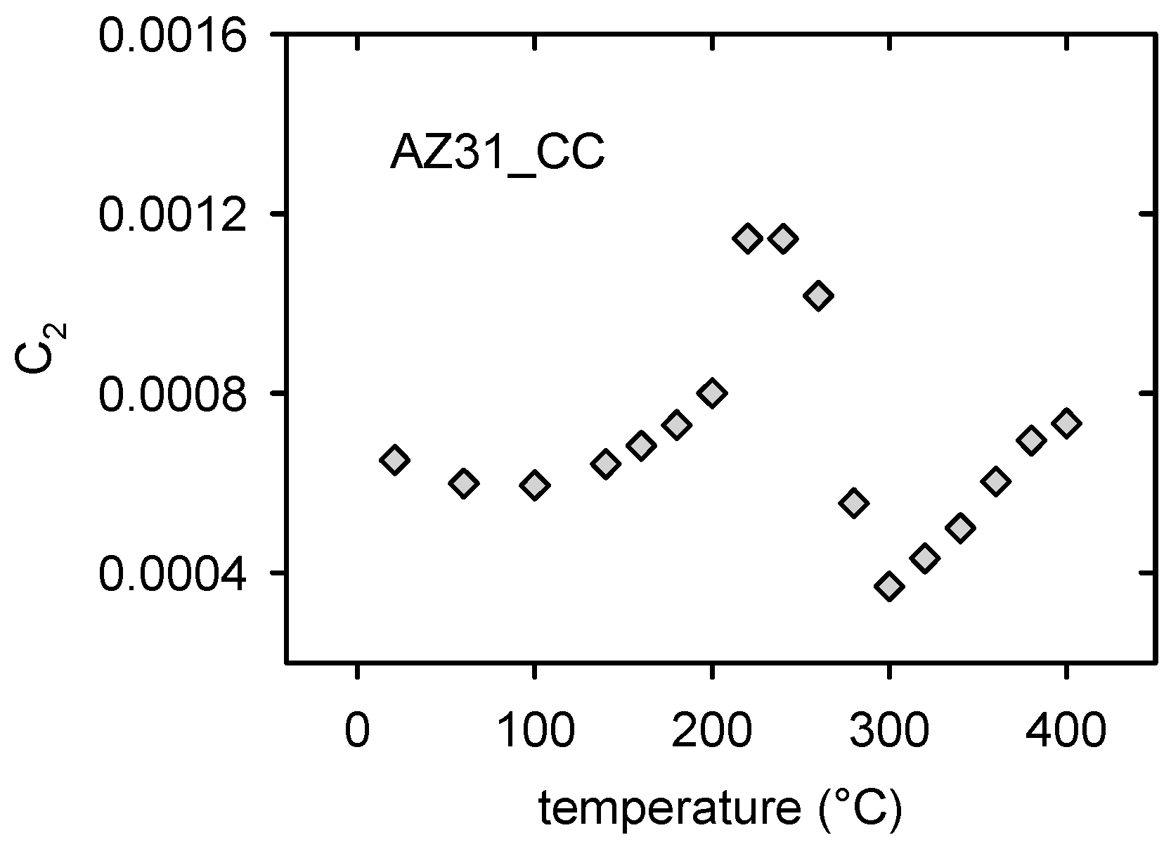
  • Main changes in the microstructure of the cast alloy occurred in the temperature region from 200 to 300 °C.
  • Redistribution of solute atoms due to the thermal treatment caused a decrease of the dislocation internal friction in the temperature range of 200–260 °C.
  • Thermal residual stresses formed due to quenching at temperatures higher than 260 °C caused microplastic deformation of the continuously cast alloy.
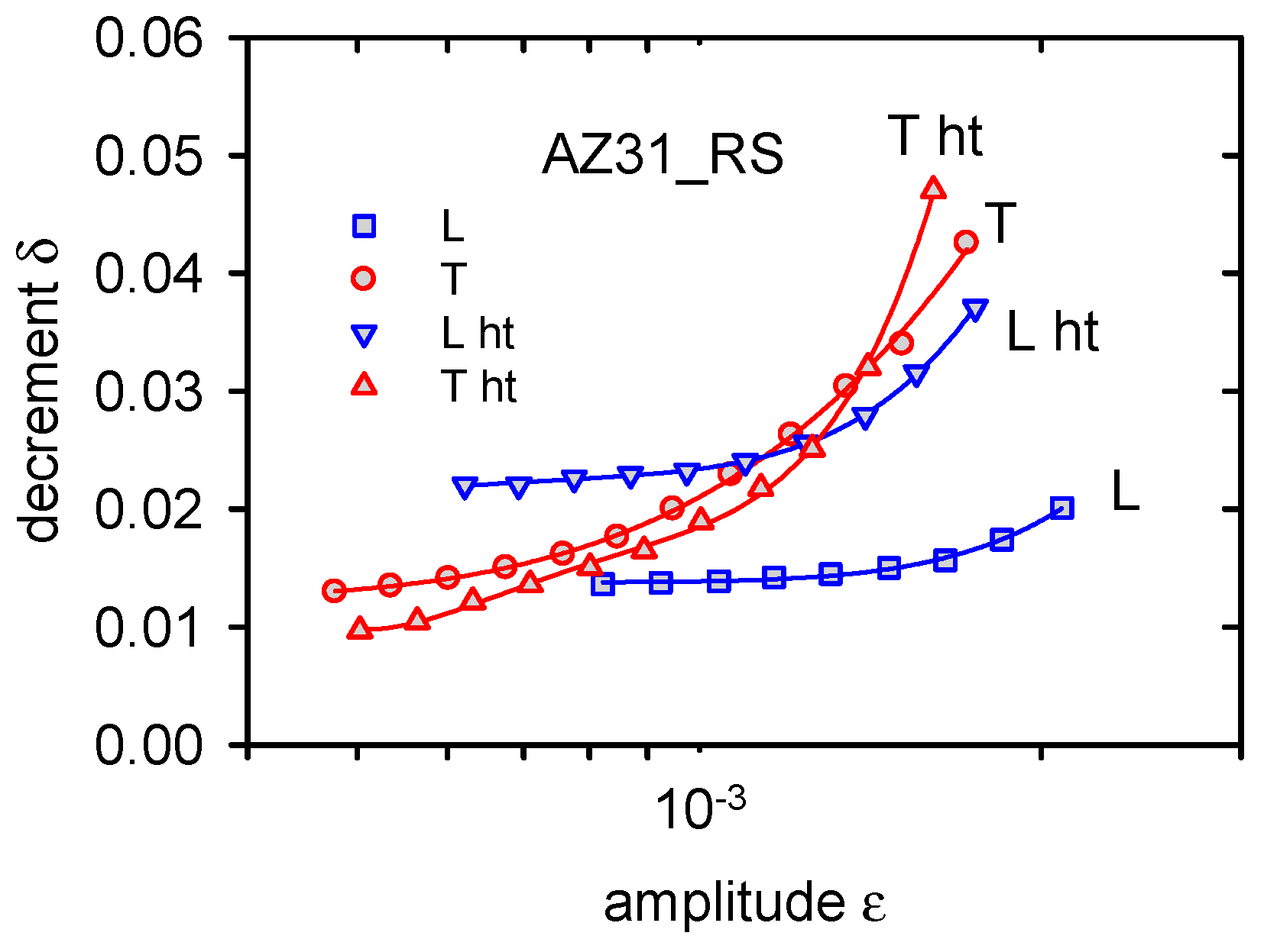
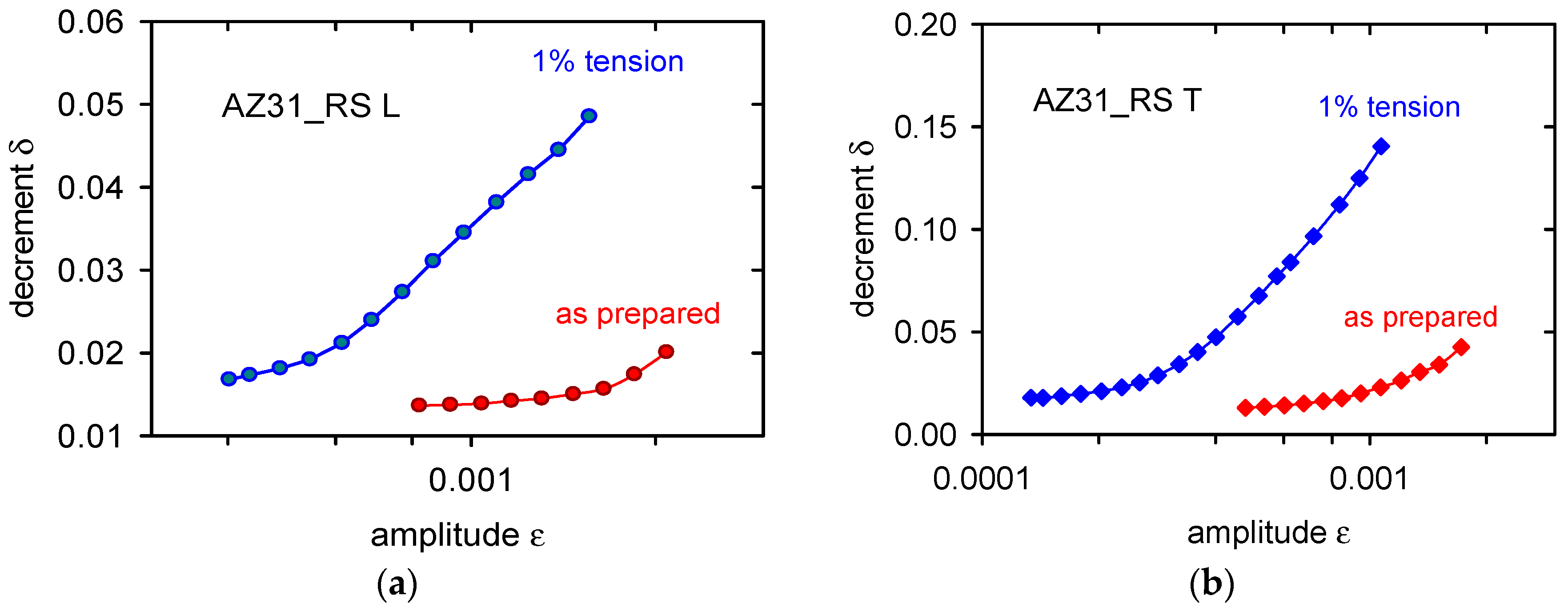
  • Basal texture in the rolled sheets strongly influences the internal friction. While dislocation internal friction is the dominant mechanism in the sample with the longest axis in the rolling direction, twins’ formation and twin boundary movement is very probably the deciding mechanism in the sample cut in the transversal direction.

Acknowledgments

Authors are grateful to the Grant Agency of the Czech Republic for the financial support (project no. 15/11879S). Authors are grateful to G. Vidrich for the provision of the continuously cast alloy.

Author Contributions

Zuzanka Trojanová conceived and designed the experiments; Zuzanka Trojanová performed the experiments; Zuzanka Trojanová and Pavel Lukáč analyzed the data; Ján Džugan and Kristýna Halmešová contributed reagents/materials/analysis tools; and Zuzanka Trojanová and Pavel Lukáč wrote the paper.

Conflicts of Interest

The authors declare no conflict of interest.

References

  1. Granato, A.V.; Lücke, K. Theory of mechanical damping due to dislocations. J. Appl. Phys. 1956, 27, 586–596. [Google Scholar] [CrossRef]
  2. Granato, A.V.; Lücke, K. Application of dislocation theory to internal friction phenomena at high frequencies. J. Appl. Phys. 1956, 27, 789–805. [Google Scholar] [CrossRef]
  3. Granato, A.V. Internal studies in dislocation motion. In Dislocation Dynamics; Rosenfield, A.R., Hahn, G.T., Bement, A.L., Jr., Jaffee, R.I., Eds.; McGraw-Hill: New York, NY, USA, 1968; p. 117. [Google Scholar]
  4. Granato, A.V.; Lücke, K. Temperature dependence of amplitude-dependent dislocation damping. J. Appl. Phys. 1981, 52, 7136–7142. [Google Scholar] [CrossRef]
  5. Teutonico, L.J.; Granato, A.V.; Lücke, K. Theory of the thermal breakaway of a pinned dislocation line with application to damping phenomena. J. Appl. Phys. 1964, 35, 220–234. [Google Scholar] [CrossRef]
  6. Marchesoni, F.; Segoloni, D. The string model of dislocation damping revisited. Acta Phys. Pol. B 1993, 24, 865–889. [Google Scholar]
  7. Gremaud, G.; Kustov, S. Non-linear elasticity due to dislocation-solute atom interaction in solid solutions. J. Alloys Compd. 2000, 310, 85–90. [Google Scholar] [CrossRef]
  8. Gremaud, G. Dislocation—Point defect interaction. In Mechanical Spectroscopy Q−1; Schaller, R., Fantozzi, G., Gremaud, G., Eds.; Trans Tech Publications: Zurich, Switzerland, 2001; pp. 178–246. [Google Scholar]
  9. D’Anna, G.; Benoit, W.; Vinokur, V.M. Internal friction and dislocation collective pinning in disordered quenched solid solutions. J. Appl. Phys. 1997, 82, 5983–5990. [Google Scholar] [CrossRef]
  10. Gremaud, G. Overview on dislocation-point defect interaction: The brownian picture of dislocation motion. Mater. Sci. Eng. A 2004, 370, 191–198. [Google Scholar] [CrossRef]
  11. Puga, H.; Carneiro, V.H.; Barbosa, J.; Soares, D. Effect of grain and secondary phase morphologies in the mechanical and damping behavior of Al7075 alloys. Met. Mater. Int. 2016, 22, 863–871. [Google Scholar] [CrossRef]
  12. Murai, T.; Matsuoka, S.; Miyamoto, S.; Oki, Y. Effects of extrusion conditions on microstructure and mechanical properties of AZ31B magnesium alloy extrusions. J. Mater. Proc. Technol. 2003, 141, 207–212. [Google Scholar] [CrossRef]
  13. Granato, A.V.; Higata, A.; Lücke, K. Recovery of damping and modulus changes following plastic deformation. Acta Metall. 1958, 6, 470–480. [Google Scholar] [CrossRef]
  14. González-Martínez, R.; Göken, J.; Letzig, D.; Timmerberg, J.; Steinhoff, K. Influence of heat treatment on damping behaviour of the magnesium wrought alloy AZ61. Acta Metall. Sin. 2007, 20, 235–240. [Google Scholar] [CrossRef]
  15. González-Martínez, R.; Göken, J.; Letzig, D.; Steinhoff, K.; Kainer, K.U. Influence of aging on damping of the magnesium-aluminium-zinc series. J. Alloys Compd. 2007, 437, 127–132. [Google Scholar] [CrossRef]
  16. Göken, J.; Riehemann, W. Damping behaviour of AZ91 magnesium alloy with cracks. Mater. Sci. Eng. A 2004, 370, 417–421. [Google Scholar] [CrossRef]
  17. Trojanová, Z.; Mielczarek, A.; Riehemann, W.; Lukáč, P. Cyclic bending and the damping behaviour of short fibre-reinforced magnesium alloy AZ91. Compos. Sci. Technol. 2000, 66, 585–590. [Google Scholar] [CrossRef]
  18. Jun, J.-H. Damping behaviour of Mg-Zn-Al castings. Mater. Sci. Eng. A 2016, 665, 86–89. [Google Scholar] [CrossRef]
  19. Lu, L.; Dahle, A.K.; Taylor, J.A.; StJohn, D.H. Theoretical and practical considerations of grain refinement of Mg-Al alloys. Mater. Sci. Forum 2005, 488–489, 299–302. [Google Scholar] [CrossRef]
  20. Vidrich, G. Grain Refinement and Dispersion-Strengthening With Finest Ceramic Particles. Ph.D. Thesis, Clausthal University of Technology, Clausthal-Zellerfeld, Germany, 2008. [Google Scholar]
  21. Trojanová, Z.; Lukáč, P.; Chmelík, F.; Riehemann, W. Microstructural changes in ZE41 composite estimated by acoustic measurements. J. Alloys Compd. 2003, 355, 113–119. [Google Scholar] [CrossRef]
  22. Trojanová, Z.; Palček, P.; Chalupová, M.; Lukáč, P.; Hlaváčová, I. High frequency cycling behaviour of three AZ magnesium alloys—Microstructural characterization. Int. J. Mater. Res. 2016, 107, 903–915. [Google Scholar] [CrossRef]
  23. Wang, J.; Duo, J.; Ding, Y.; Tang, B. Thermal Cycling Behavior of Mg-4%Sn-2.5%Pb Alloy. J. Residuals Sci. Technol. (JRST) 2017, 14, 420–425. [Google Scholar] [CrossRef]
  24. Debye, P. Zur Theorie der spezifischen Wärmen. Annalen der Physik 1912, 39, 789–839. [Google Scholar] [CrossRef]
  25. Bohlen, J.; Chmelík, F.; Dobroň, P.; Kaiser, F.; Letzig, D.; Lukáč, P.; Kainer, K.U. Orientation effects on acoustic emission during tensile deformation of hot rolled magnesium alloy AZ31. J. Alloys Compd. 2004, 378, 207–213. [Google Scholar] [CrossRef]
  26. Victoria-Hernandez, J.; Yi, J.; Bohlen, J.; Kurz, G.; Letzig, D. The influence of the recrystallization mechanisms and grain growth on the texture of a hot rolled AZ31 sheet during subsequent isochronal annealing. J. Alloys Compd. 2014, 616, 189–197. [Google Scholar] [CrossRef]
  27. Wang, Y.N.; Huang, J.C. The role of twinning and untwinning in yielding behavior in hot-extruded Mg-Al-Zn alloy. Acta Mater. 2007, 55, 897–905. [Google Scholar] [CrossRef]
  28. Klimanek, P.; Pötzsch, A. Microstructure evolution under compressive plastic deformation of magnesium at different temperatures and strain rates. Mater. Sci. Eng. A 2002, 324, 145–150. [Google Scholar] [CrossRef]
  29. Huang, H.T.; Godfrey, A.; Zheng, J.P.; Liu, W. Influence of locat strain on twinning behavior during compression of AZ31 magnesium alloy. Mater. Sci. Eng. A 2015, 640, 330–337. [Google Scholar] [CrossRef]
  30. Yang, P.; Yu, Y.; Chen, L.; Mao, W. Experimental determination and theoretical prediction of twin orientations in magnesium alloy AZ31. Scr. Mater. 2014, 50, 1163–1168. [Google Scholar] [CrossRef]
  31. Hou, D.; Liu, T.; Luo, L.; Lu, L.; Chen, H.; Shi, D. Twinning behaviors of a rolled AZ31 magnesium alloy under multidirectional loading. Mater. Charact. 2017, 124, 122–128. [Google Scholar] [CrossRef]
  32. Wu, L.; Agnew, S.R.; Ren, Y.; Brown, D.W.; Clausen, B.; Stoica, G.M.; Wenk, H.R.; Liaw, P.K. The effects of texture and extension twinning on the low-cycle fatigue behavior of a rolled magnesium alloy, AZ31B. Mater. Sci. Eng. A 2010, 527, 7057–7706. [Google Scholar] [CrossRef]
  33. Watanabe, H.; Sasakura, Y.; Ikeo, N.; Mukai, T. Effect of deformation twins on damping capacity in extruded pure magnesium. J. Alloys Compd. 2015, 626, 60–64. [Google Scholar] [CrossRef]
  34. Stráská, J.; Janeček, M.; Čížek, J.; Stráský, J.; Hadzima, B. Microstructure stability of ultra-fine grained magnesium alloy AZ31 processed by extrusion and equal channel angular pressing (EX-ECAP). Mater. Charact. 2014, 94, 69–79. [Google Scholar] [CrossRef]
Figure 1. Microstructure of the as-prepared AZ31 alloy: (a) light micrograph; and (b) scanning electron micrograph showing identified phases.
Metals 07 00433 g001
Figure 2. Microstructure of the as prepared AZ31_RS sample (a); and the pole figure taken from the sheet surface (b).
Metals 07 00433 g002
Figure 3. Amplitude dependences of decrement measured for lower temperatures from 60 up to 200 °C (a); for medium temperatures from 200 up to 260 °C (b); and for high temperatures from 260 up to 400 °C (c). Indicated temperatures are the upper temperatures of the quenching cycle.
Metals 07 00433 g003
Figure 4. Temperature dependence of amplitudes necessary for achieving damping values of δH = 1 × 10⁻³ and δH = 5 × 10⁻³.
Metals 07 00433 g004
Figure 5. Partially-dissolved precipitates in the microstructure of AZ31_CC after annealing and quenching step by step up to 400 °C.
Metals 07 00433 g005
Figure 6. Amplitude dependent decrement estimated for two orientations of AZ31_RS samples in the as-received state and after heat treatment (ht).
Metals 07 00433 g006
Figure 7. Microstructure of AZ31_RS after heat treatment up to 400 °C.
Metals 07 00433 g007
Figure 8. Influence of pre-staining in tension on ADIF: (a) L orientation; and (b) T orientation.
Metals 07 00433 g008
Figure 9. G-L fit for the curve measured after thermal cycling up to 200 °C.
Metals 07 00433 g009
Figure 10. Amplitude independent component of decrement depending on the upper temperature of the thermal cycle.
Metals 07 00433 g010
Figure 11. The fitting parameter C1 depending on the upper temperature of the thermal cycle.
Metals 07 00433 g011
Figure 12. The fitting parameter C2 vs. the upper temperature of the thermal cycle.
Metals 07 00433 g012
Figure 13. Temperature dependence of the thermal expansion coefficient.
Metals 07 00433 g013
Figure 14. Schematic illustration of the sample geometry with respect to the hexagonal cell: (a) L orientation; (b) T orientation.
Metals 07 00433 g014
Table 1. Chemical composition of materials used (in wt %).
MaterialAlZnMnSiFeCeMg
AZ31_CC3.50.90.40.06<0.01-Bal.
AZ31_RS3.21.30.40.0150.030.06Bal.

