Article

Effect of Welding Heat Input on the Microstructure and Toughness in Simulated CGHAZ of 800 MPa-Grade Steel for Hydropower Penstocks

1
Laboratory of Metastable Materials Science and Technology, Yanshan University, Qinhuangdao 066004, China
2
National Engineering Research Center for Equipment and Technology of Cold Strip Rolling, Yanshan University, Qinhuangdao 066004, China
*
Author to whom correspondence should be addressed.
Metals 2017, 7(4), 115; https://doi.org/10.3390/met7040115
Submission received: 22 January 2017 / Revised: 23 March 2017 / Accepted: 23 March 2017 / Published: 27 March 2017

Abstract

:
To determine the appropriate welding heat input for simulated coarse grained heat affected zone (CGHAZ) of 800 MPa-grade steel used in hydropower penstocks, the microstructural evolution, hardness, and 50% fraction appearance transition temperature (50% FATT) were investigated. The results indicated that when the cooling rate (heat input) is reduced (increased), the impact toughness at −20 °C and hardness of the simulated CGHAZ decreased. When the heat input increased from 18 to 81 kJ/cm, the 50% FATT increased from −80 °C to −11 °C. At 18 kJ/cm, the microstructures consisted of lath bainite and granular bainite, but lath bainite decreased with increasing heat input. The increase in the 50% FATT was attributed mainly to an increase in the austenite grain size and effective grain size, and a decrease in lath bainite and the fraction of HAGBs (misorientation: ≥15°).

1. Introduction

With the development of society, hydropower has become increasingly important as a source of clean, renewable energy. Nowadays, owing to the capacity of hydropower stations, steels for hydropower applications must exhibit high strength, good toughness, and excellent weldability.
High-strength low-alloy steel (HSLA), with appropriate strength and toughness, has been widely used as structural steel. The balance of high strength and good toughness in HSLA steels has, however, always been upset by the welding thermal cycle, which (i) is characterized by rapid heating and high peak temperature; and (ii) produces areas of poor toughness known as heat affected zones (HAZs) [1,2,3]. Furthermore, the coarse grained heat affected zone (CGHAZ), which lies adjacent to the weld fusion line and experiences peak temperatures of 1350 °C or higher, is one of the weakest parts of these HAZs [4]. During the welding heat process, significant austenite grain growth may occur in the CGHAZ, leading to the formation of coarse granular bainitic, ferrite side-plate microstructures after completion of the weld. These microstructures are sensitive to cleavage cracking [5], which generates regions of poor toughness referred to as local brittle zones (LBZs).
How to minimize the decrease in toughness of the CGHAZ remains the great challenge. Attempts should be made to attain adequate impact toughness at −20 °C for safer application of 800 MPa-grade hydropower steel. For this purpose, the selection of welding heat input is important. Previous work has indicated that increasing heat input causes coarsening of prior austenite grain (PAG) due to the decreasing cooling rate, leading to a decrease in toughness [6]. Additionally, both the coarse upper bainite and the martensite-austenite (M-A) constituents also have a deleterious effect on the impact toughness in weld CGHAZ of low-carbon HSLA steel [7]. Guo et al. [8] have further reported that the impact toughness in the simulated CGHAZ of X 90 pipeline steel increases with the refinement of the bainite packet due to decreasing the heat input, and is governed by the bainitic packet. Kumar and Nath have observed that ductile to brittle transition temperature (DBTT) for weld CGHAZ of a HY 85 steel increases slightly with increasing heat input from 15 to 50 kJ/cm, due to increase in width of bainitic lath [9]. Cao et al. [10] have also found that that the impact toughness decreases and DBTT increases with increasing heat input owing to increase in PAGS.
Therefore, in the present work, the effect of welding heat input on the microstructures formed in the CGHAZ of 800 MPa-grade steel for hydropower penstocks and on the corresponding mechanical properties is elucidated. The microstructure and crystallographic orientations of the CGHAZ were evaluated via transmission electron microscopy (TEM) and electron backscatter diffraction (EBSD), respectively. The dependence of microstructural evolution and mechanical properties on the heat input was clarified.

2. Materials and Methods

2.1. Materials

The chemical composition of the 800 MPa-grade steel is shown in Table 1. The microstructure of the experimental steel sample was revealed by etching with a 4 vol % nital solution, and observed using an Axiover-200MAT optical microscope (OM, Axiover, Oberkochen, Germany). It consists of lath bainite, quasi-polygonal ferrite, and granular bainite, as shown in Figure 1.

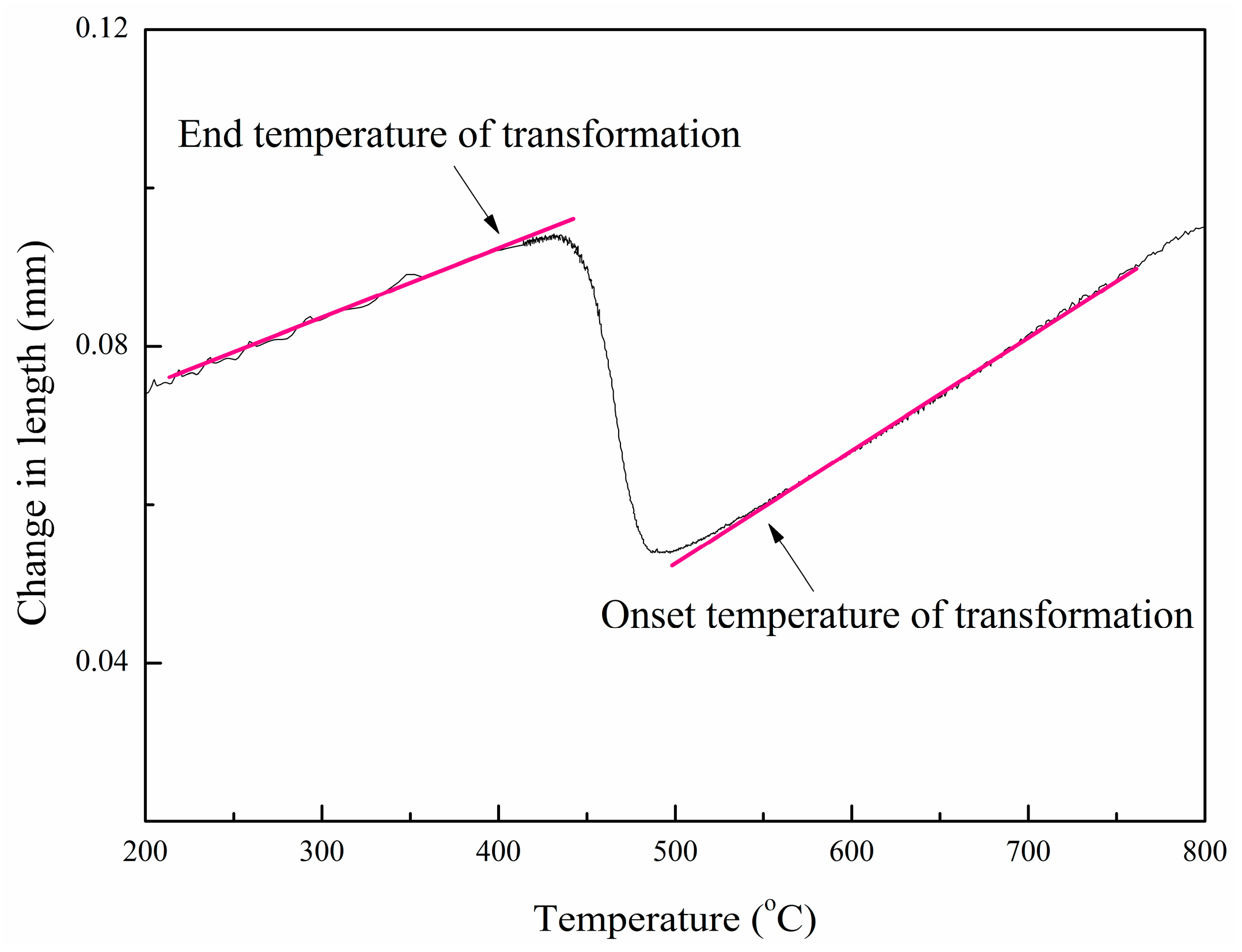
2.2. Weld CGHAZ Simulation and the Onset and End Temperatures for Transformation Determination

Microstructural evolution and mechanical property variation in the CGHAZ were investigated through a welding thermal cycle simulation conducted on a Gleeble-3500 thermal simulator (DSI, Poestenkill, NY, USA). For determination of the onset and end temperatures for continuous cooling transformation of the simulated CGHAZ, the simulated specimens were cut from the as-rolled steel plate, along the longitudinal direction, and then machined to sizes of φ10 mm × 80 mm. In addition, the welding thermal cycle curves were determined by using the two-dimensional (2D) Rykalin mathematical model to simulate the thermal cycle process, as shown in Figure 2. The specimens were heated to 1320 °C at 100 °C/s, and then held for 1 s. To simulate different welding heat inputs, the specimens were cooled from 1320 °C to 800 °C by experiencing increased cooling time of 4 s, 7 s, 9 s, 13 s, 18 s, 26 s, 44 s, 88 s, and 133 s, and further from 800 °C to 500 °C (t8/5) for 10 s, 15 s, 20 s, 30 s, 40 s, 60 s, 100 s, 200 s, and 300 s. The welding input values associated with these times were equivalent to actual welding input values of 18 kJ/cm, 22 kJ/cm, 25 kJ/cm, 31 kJ/cm, 36 kJ/cm, 44 kJ/cm, 57 kJ/cm, 81 kJ/cm, and 99 kJ/cm, respectively. Each thermal dilation curve was measured with the dilatometry fixed on the sample at the same cross-section as the thermal couples, as shown in Figure 3, and the onset and end temperatures for transformation indicating 5% and 95% fraction transformed were then determined via the tangent method according to the standard of GB 5056-85.
For examination of mechanical properties of the simulated CGHAZ, the specimens were cut in the same way, and then machined to sizes of 10.5 mm × 10.5 mm × 65 mm, and the welding thermal cycles for heat input values of 18 kJ/cm, 25 kJ/cm, 31 kJ/cm, 44 kJ/cm, and 81 kJ/cm were simulated according to the same procedure as described above.
The simulator used in the present work is constituted by a 75 kilowatt resistant heater (DSI, St. Paul, MN, USA), an ISO-quenching system (DSI, St. Paul, MN, USA), and a digital controller (DSI, St. Paul, MN, USA). It can impose high-precision welding thermal cycles of various heat inputs on the samples. With the free span between two copper jaws properly selected, the temperature gradient along the length of the sample was minimized, and a uniform thermal zone of ~5 mm in width with the difference in temperature less than 10 °C was obtained enough for the microstructure and impact toughness examinations.

2.3. Mechanical Properties

The specimens subjected to different welding thermal cycles were machined into standard Charpy V-notch samples with sizes of 10 mm × 10 mm × 55 mm, and the notch tip was placed in the center of the simulated CGHAZ. The impact tests were conducted on an NCS (National Analysis Center iron steel) drop weight impact tester, at temperatures ranging from −100 °C to 0 °C. For testing at –100 °C, a mixture of liquid nitrogen (Sihai, Qinhuangdao, China) and alcohol (Kaitong chemistry, Tianjin, China) was used for cooling the samples. The 50% FATT, i.e., 50% fraction appearance transition temperature, refers to the temperature at which the ductile or brittle zone accounts for 50% area fraction of total fractured zone in a ruptured impact sample. It can be normally used for characterizing the effect of temperature on toughness or brittleness [11,12,13]. Lower the 50% FATT, better the toughness. For determining the 50% FATT for one welding CGHAZ, The area fractions of ductile fiber for three impact samples at each temperature were measured, averaged and plotted vs. temperature, and the 50% fraction point was located.

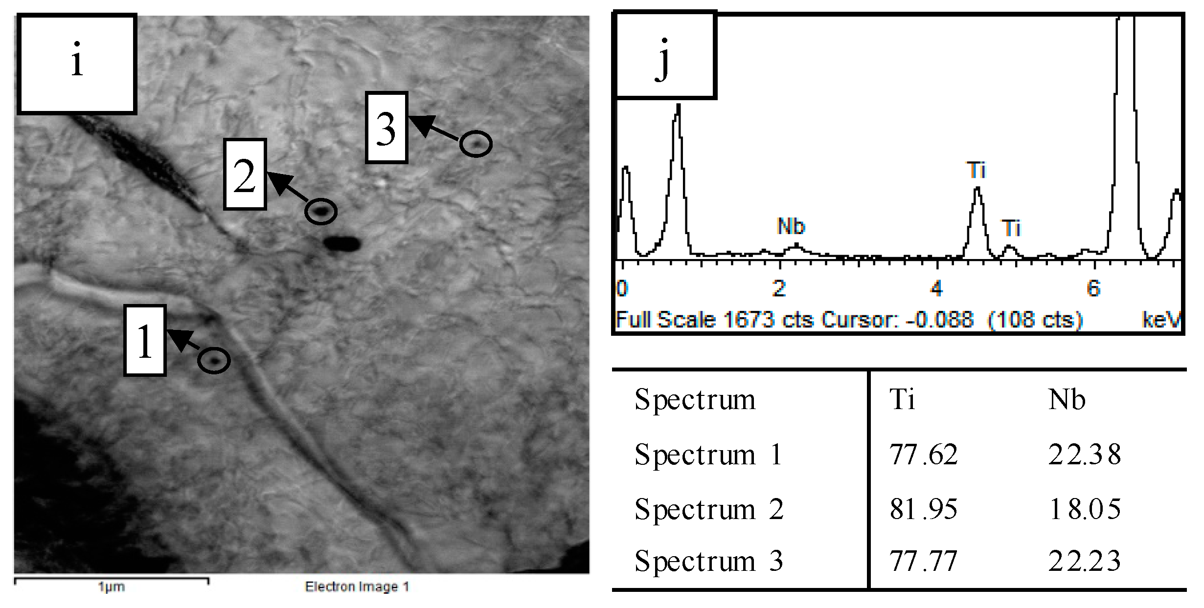
2.4. Microstructural Characterization

The specimens were manufactured via standard techniques, etched with a 4 vol % nital solution, and observed using an Axiover-200MAT optical microscope (OM) (Axiover, Oberkochen, Germany). The prior austenite grains (PAGs) were etched in supersaturated picric acid and the average PAG size was determined from at least 500 PAGs in more than 10 fields of view at a magnification of 200× using the standard linear intercept methods. For electron backscattered diffraction (EBSD) (Hitachi, Tokyo, Japan) examinations, the samples were electrolytically polished in a solution of perchloric acid (Zhengcheng chemistry, Tianjin, China) and ethyl alcohol (Kaitong chemistry, Tianjin, China), and scanned on a Hitachi S-3400 scanning electron microscope (SEM, Hitachi, Tokyo, Japan) equipped with a Tex SEM Laboratories (TSL) EBSD system with a step size of 0.3 μm and Flamenco software (1.0, Oxford, London, UK). The EBSD maps were analyzed by HKL-Channel 5 software (5.0, Oxford, London, UK). In addition, the EBSD effective grain size was calculated as the equivalent circle diameter related to the individual grain area. Tolerance angles of 2–30° were applied. The tolerance angle corresponds here to the threshold misorientation angle used for recognizing a grain boundary. The polished specimens were etched with Lepera reagent to reveal the morphology of the M-A constituents. Measurements of area fraction of M-A constituents were performed mainly using image analysis with the software Image-Pro Plus (Media Cybernetics, Rockville, MD, USA). For each specimen, at least 10 fields of view containing at least 1000 M-A constituents were measured at a magnification of 1000×. The detailed bainitic microstructure and precipitates in the simulated CGHAZ were observed using thin foils in a JEM-2010 high-resolution transmission electron microscope (TEM, JEOL, Tokyo, Japan). The composition of these precipitates was determined via energy-dispersive X-ray spectroscopy (EDX, Rigaku, Tokyo, Japan).

3. Results

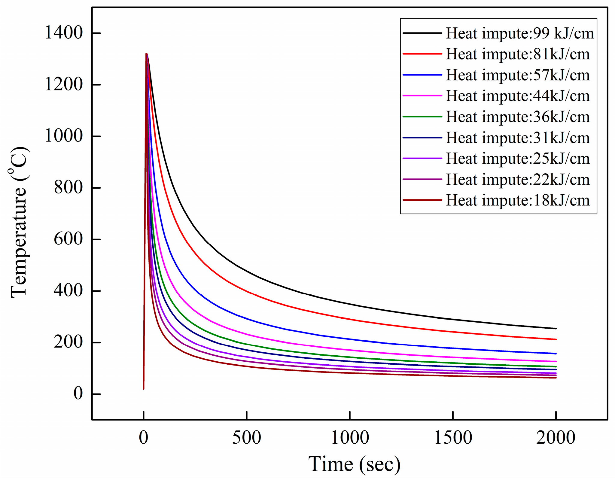
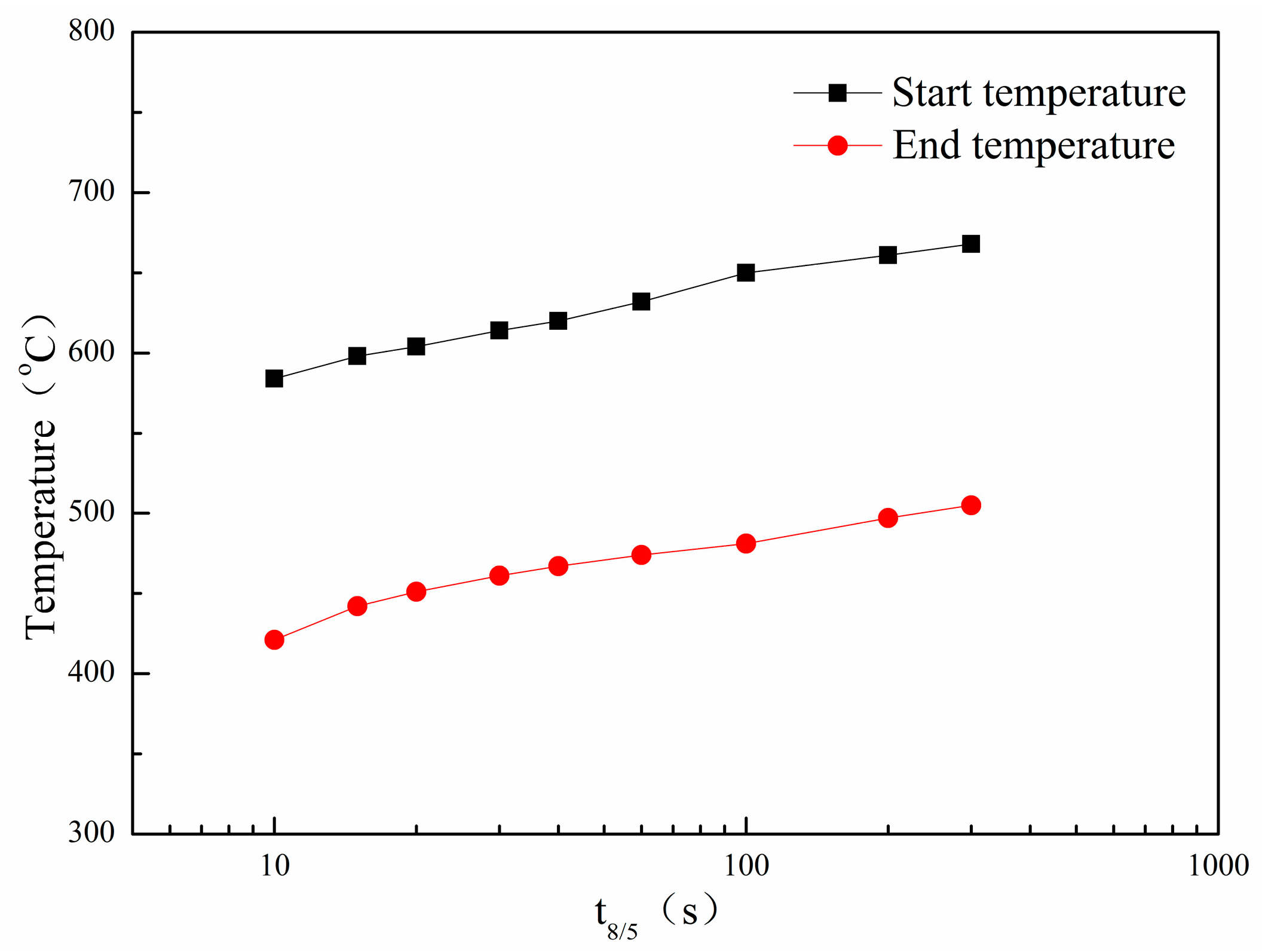
3.1. Continuous Cooling Transformation Occurring in the Simulated CGHAZ

Figure 4 shows the effect of t8/5 on the onset and end temperatures for continuous cooling phase transformation occurring in the simulated CGHAZ and Figure 5 shows the CGHAZ microstructure of the experimental steel for t8/5 at (a) 10 s, (b) 20s, (c) 40 s, and (d) 200 s. It can be seen that the simulated CGHAZ microstructure is bainite in the t8/5 range of 10–200 s, and the onset temperature for transformation decreases with decreasing t8/5. At low t8/5, i.e., 10 s, a predominant lath bainite microstructure forms, as shown in Figure 5a, but while at 20–200 s, the microstructure is composed of lath-like and granular bainite (see Figure 5b–d). With an increase in t8/5, the phase transformation temperature and, correspondingly, granular bainite increase, whereas lath bainite decreases according to the metallographic observations.

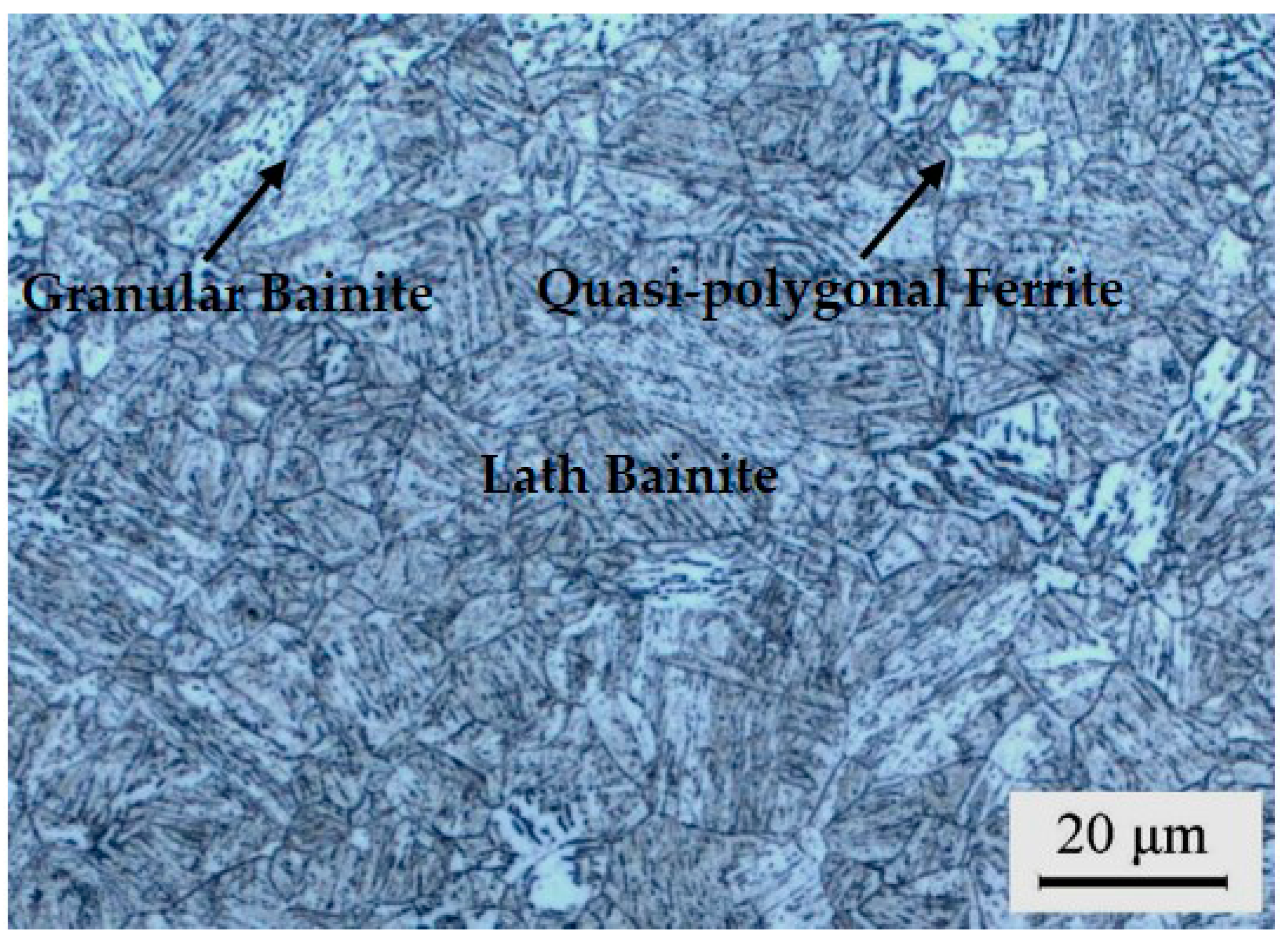
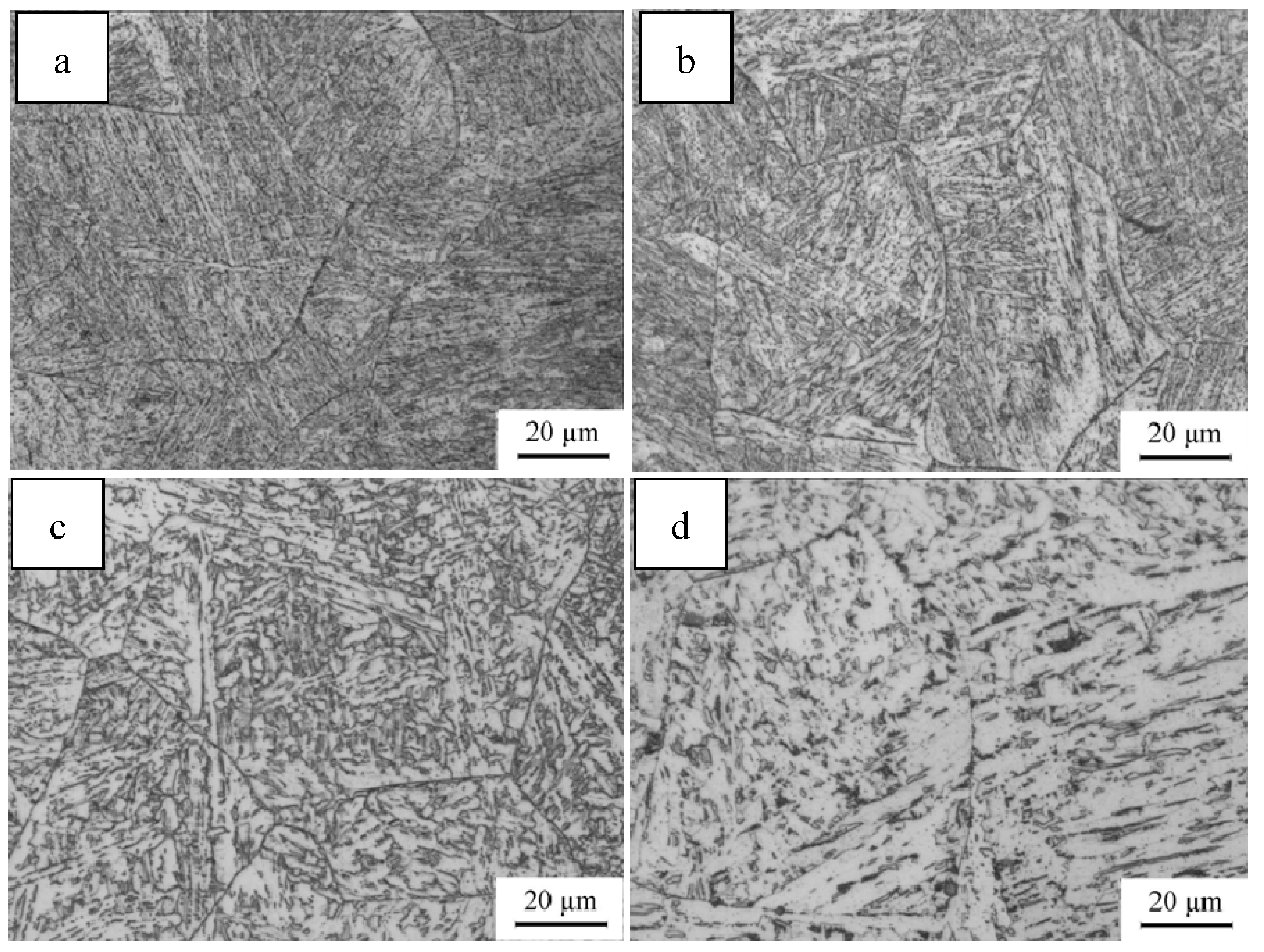
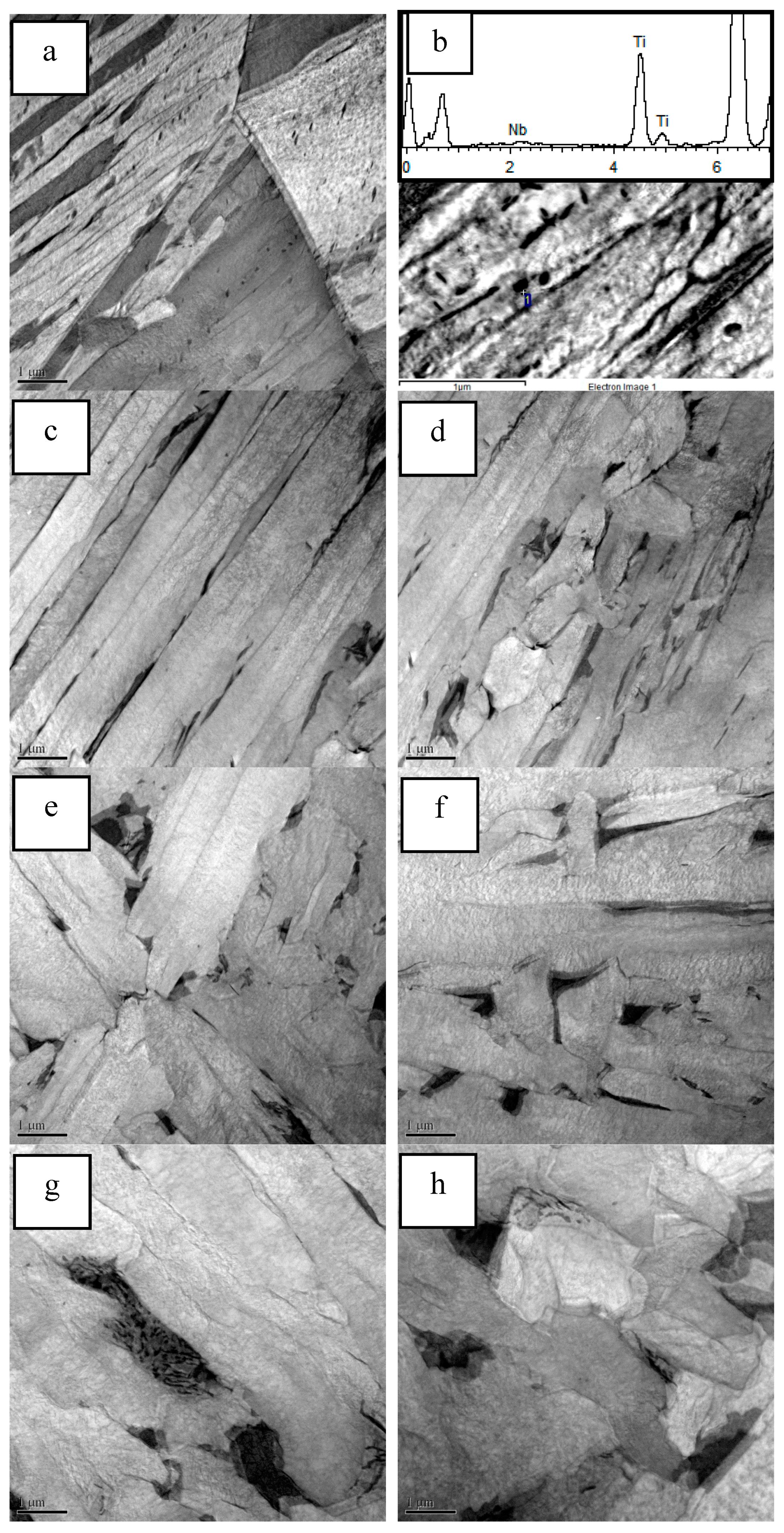
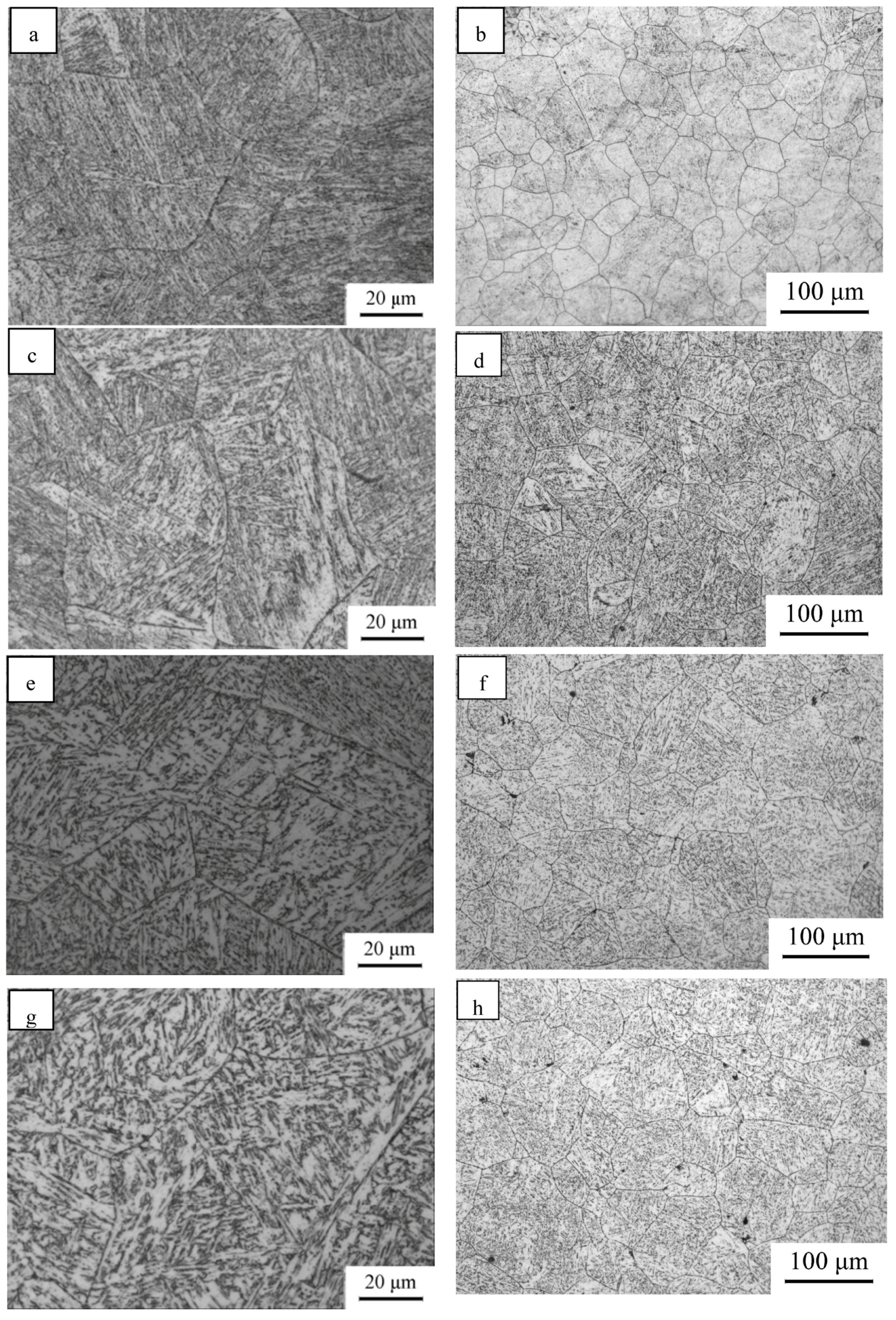
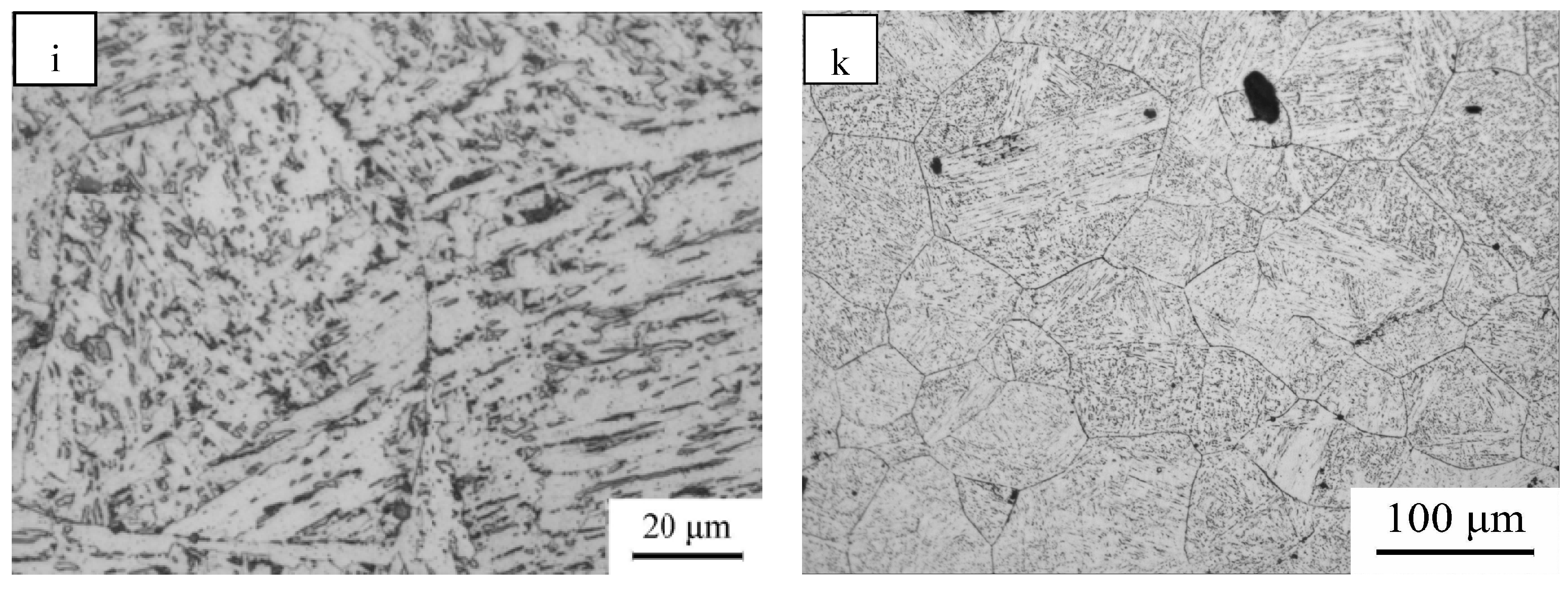
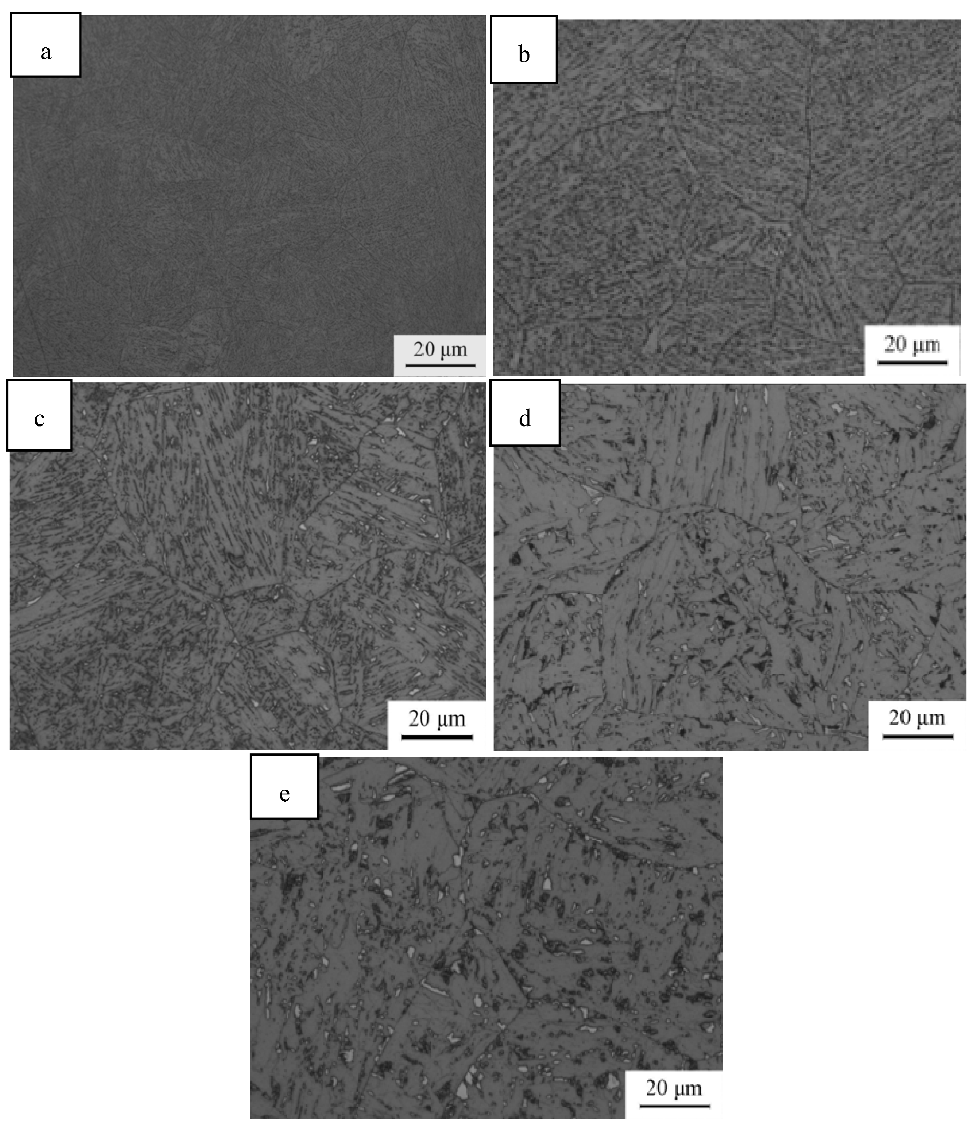
3.2. Microstructure of Simulatied CGHAZ

Figure 6 shows the CGHAZ microstructures and the prior austenite grain of experimental steel exposed to the different thermal cycles corresponding to different heat input welding. At an input of 18 kJ/cm, the microstructures are composed of lath bainite (LB) and granular bainite (GB). The bainite sheaf nucleated and grew from prior austenite grain boundaries, and some of the packets originating from the different prior austenite grains were interconnected, as shown in Figure 6a. The amount of GB increased with increasing heat input, whereas the amount of LB decreased (see Figure 6c,e,g). At an input of 81 kJ/cm, the microstructures are composed mainly of GB and LB, and a small amount of degenerated pearlite (DP), as shown in Figure 6i. Figure 6b,d,f,k reveal the austenite grain morphologies, while Figure 7 shows the prior austenite grain size of the experimental steel quenched at different heat input. As the figure shows, the grain size increases (from 45.5 μm at 18 kJ/cm to 101 μm at 81 kJ/cm) with increasing heat input.
Figure 8 shows the inverse pole figure (IPF) maps with grain boundaries colored according to the magnitude of the corresponding misorientation. For example, the black and white lines correspond to high-angle and low-angle grain boundaries (HAGBs and LAGBs), which are described by misorientations of 2–15° and misorientations of ≥15°, respectively. The misorientation relationships in the intricate bainite packets correspond predominantly to HAGBs, and only a low fraction of LAGBs occur in lath bainite.
Although HAGBs can effectively deflect or even inhibit the propagation of cleavage cracks, thereby increasing the crack propagation energy, LAGBs lead to only slight deviation of the cleavage crack [14,15]. The grain size effective for achieving high strength and toughness are typically defined using threshold misorientations of 2° and 15°, respectively [16,17,18]. The EBSD results plotted as a function of the heat input (Figure 9) reveals that the mean equivalent diameter (MED) increases, whereas the frequency of HAGBs decreases, monotonously with increasing heat input.
Figure 10 shows the M-A morphology of the simulated CGHAZ at different heat inputs. At low t8/5, the M-A is fine and comprises only a small fraction of the microstructure, as shown in Figure 10a. The M-A is located between ferrite blocks, and the size and content thereof increase with increasing heat input (see Figure 10). Figure 11 shows the area fraction of M-A constituent of the simulated CGHAZ at different heat inputs. The area fraction of M-A constituent increases slightly with increasing heat input from 18–30 kJ/cm, and further increases significantly with increasing heat input from 30–81 kJ/cm.
Figure 12 shows TEM micrographs of the microstructure of the simulated CGHAZ in the experimental steel. At 18 kJ/cm, 25 kJ/cm, 44 kJ/cm, and 81 kJ/cm, the microstructure consists of: (i) lath ferrite (size: ~200 nm), a high density of carbides, and a small fraction of (Nb,Ti)(C,N) precipitates lying on the ferrite; (ii) M-A constituents sandwiched between lath ferrite (size: ~1 μm) (see Figure 12c,d); (iii) strip M-A constituents (located between the ferrite blocks)—these constituents and the lath ferrite coarsen with increasing welding heat input (see Figure 12e,f); (iv) Fe3C resulting from the decomposition of the M/A constituents—the strip M-A constituents replaced gradually by the block M-A ones (see Figure 12g,h); and (v) a small amount of coarsening (Nb,Ti)(C,N) precipitates lying on the ferrite (see Figure 12i), respectively.

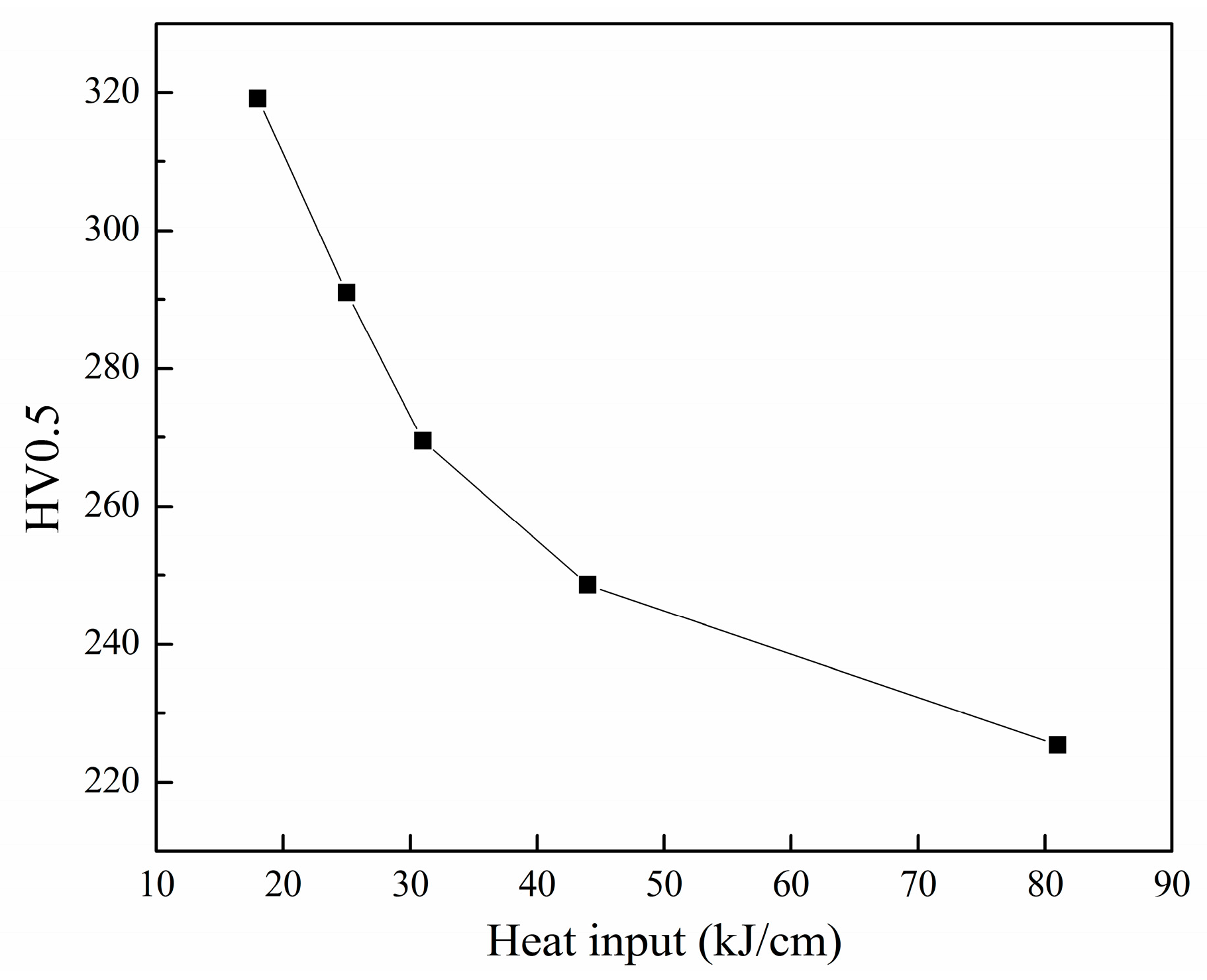
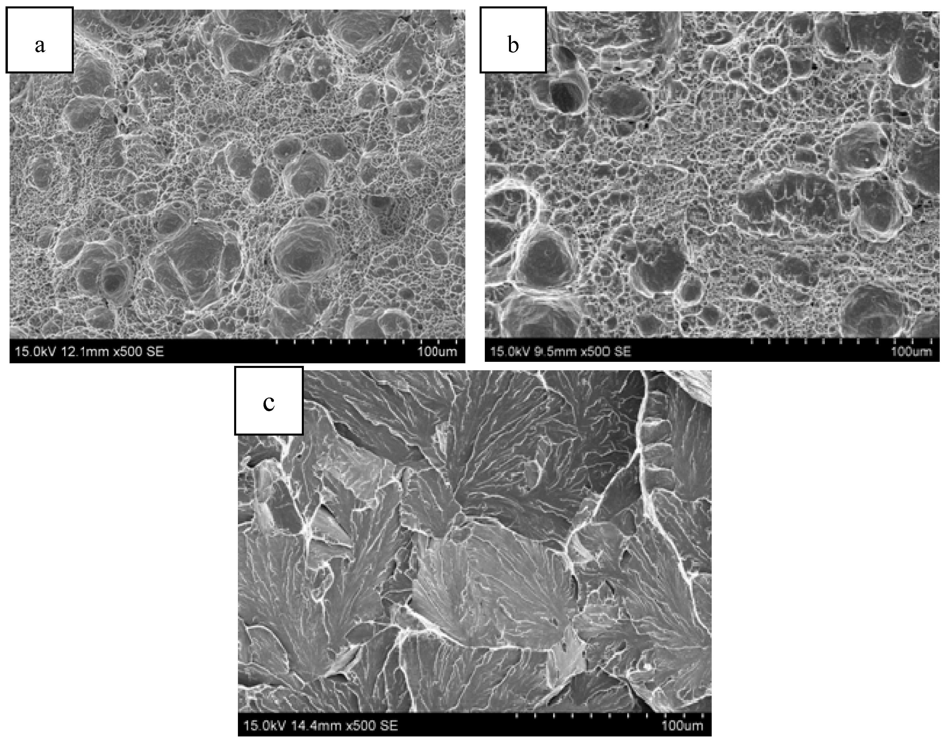
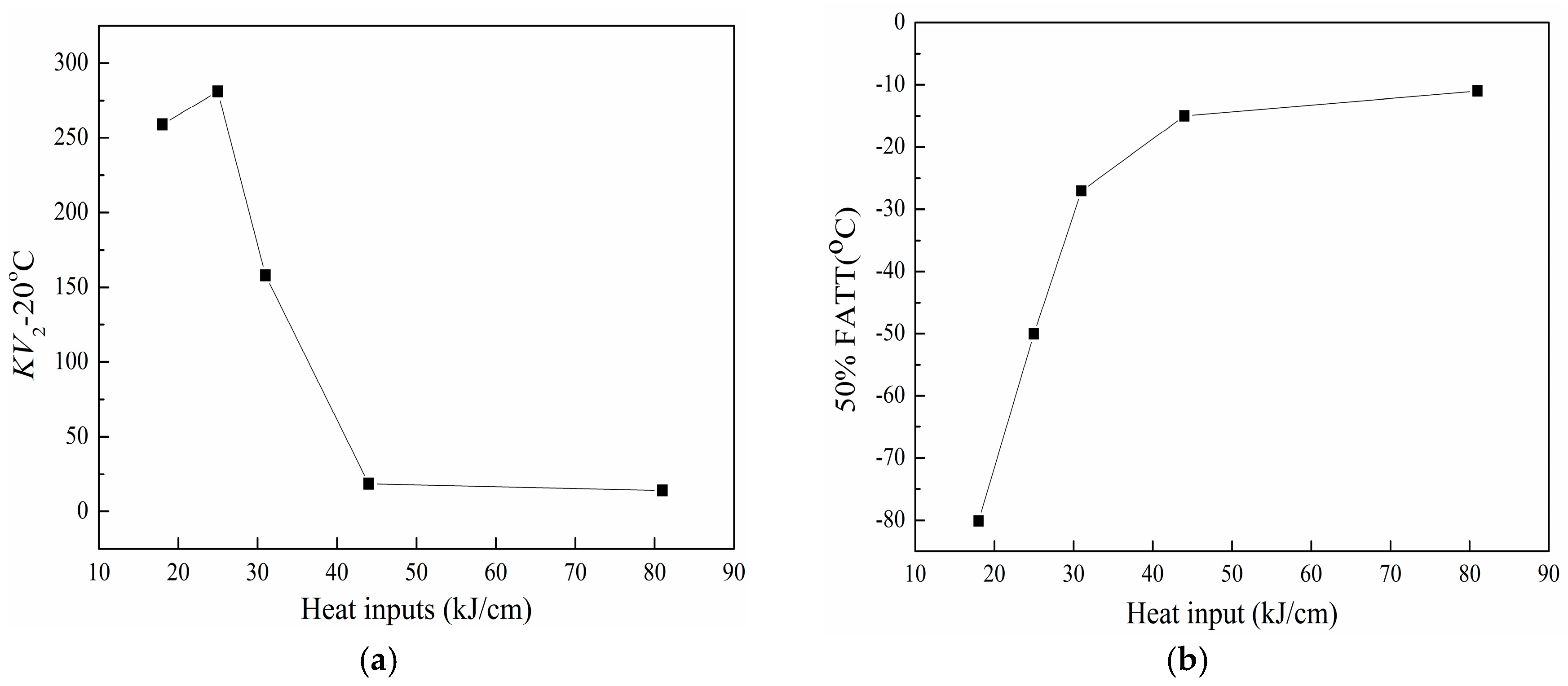
3.3. Mechanical Properties of the Simulated CGHAZ

Figure 13 shows the hardness of the simulated CGHAZ at different heat inputs. The figure shows that the hardness decreases rapidly (from 319 HV0.5 at 18 kJ/cm to 225 HV0.5 at 81 kJ/cm) with increasing heat input. The toughness and 50% FATT of the simulated CGHAZ at different heat inputs are shown in Figure 14. As the figure shows, the 50% FATT increases (from −80 °C at 18 kJ/cm to −11 °C at 81 kJ/cm) with increasing heat input.
Figure 15 shows SEM micrographs of the surface morphologies resulting from impact fracture at −20 °C. The morphology of the microstructure, related to the spatial distribution of HAGBs and LAGBs, is expected to play an important role in the crack propagation process. At 18 and 25 kJ/cm, the fracture surface is composed of both large and small ductile dimples (see Figure 15a,b). At 81 kJ/cm, the specimen undergoes cleavage fracture and, hence, the fracture surface is composed of cleavage facets and tearing edges with small dimples (see Figure 15c).

4. Discussion

4.1. Effect of Heat Input on the Simulated CGHAZ Microstructure

At low heat input parameters, and accordingly high cooling rates, the phase transformation occurs in the simulated CGHAZ under a high degree of super cooling and carbon diffusion is slowed, owing to the low carbon content of the γ/α interface. This leads to ferrite formation and the subsequent formation of lath bainite [19]. At high heat input parameters, and accordingly low cooling rates, granular bainite forms (after ferrite nucleation), resulting possibly from carbon diffusion into austenite. This diffusion increases the carbon concentration of austenite leading to a decrease in the γ→α phase transformation temperature [19,20]. At a heat input of 18 kJ/cm, the cooling rate is high and the carbon diffusion rate is low, owing to the lath morphology of the ferrite. When the heat input is increased: the cooling rate decreases, carbon diffuses to the γ phase after α formation, resulting in a decrease in the transformation temperature of the retained γ phase, and M-A constituent and carbide are then formed, as shown in Figure 12.

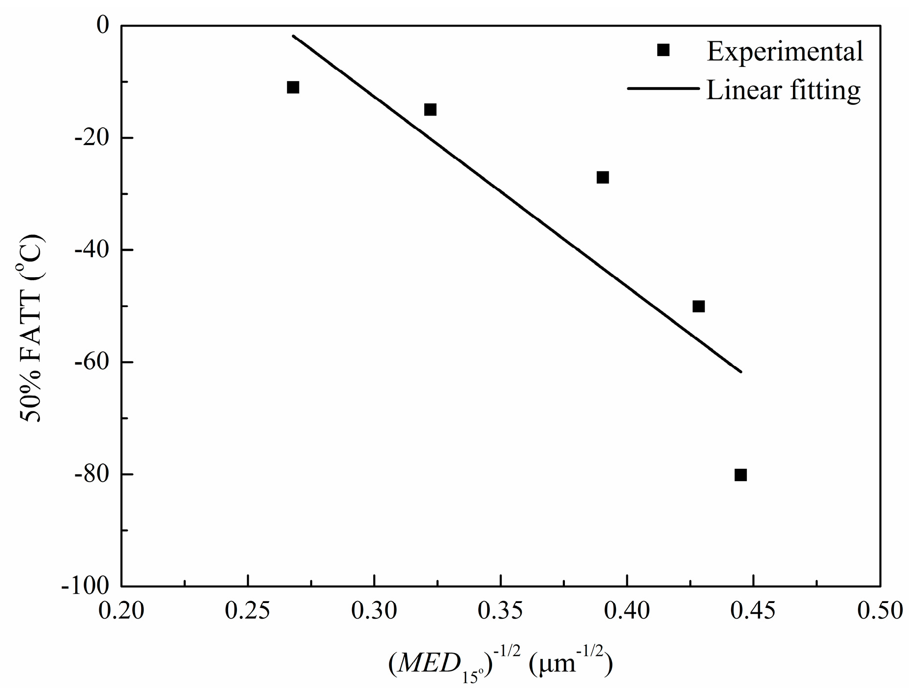
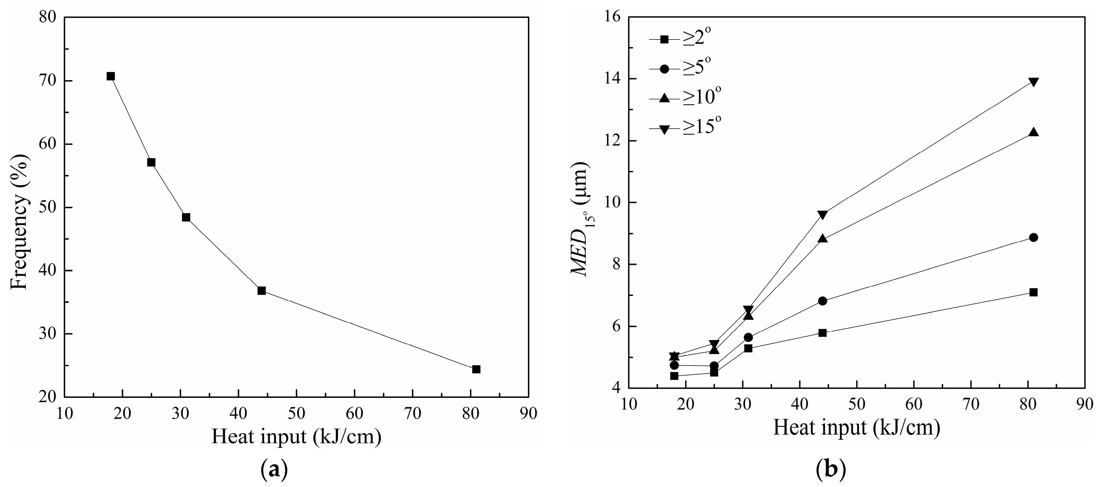
4.2. Effect of Effective Grain Size on 50% FATT of the Simulated CGHAZ

At 18 kJ/cm, the simulated CGHAZ had the smallest austenite grain size and this austenite transforms to lath bainite and granular bainite after the weld thermal cycle. Furthermore, the HAGBs (misorientation: ≥15°), which occur with a high frequency (70.7%), can efficiently deflect, or even inhibit, the propagation of cleavage cracks, thereby increasing the crack propagation energy. The HAGBs provide effective barriers to cleavage fracture and, hence, 15° is taken as the threshold angle that defines the cleavage unit size [13].
Figure 9 shows the effective grain size of the simulated CGHAZ at different heat inputs. The smallest effective grain size and, therefore, high toughness of the CGHAZ occur at an input of 18 kJ/cm. Moreover, the prior austenite grain size and effective grain size increase, the fraction of lath bainite and fraction of HAGBs decrease, and the 50% FATT increases with increasing heat input.
The dependence of the ductile-brittle transition temperature on the root square of the distance between HAGBs is usually expressed as an inverse proportionality. Based on the work of Pickering [12], the ductile-brittle transition temperature (50% FATT) can be expressed as follows:
T = T 0 K d 1 / 2
where K is a constant. T0 depends only on the tensile properties of the material, and d is the mean linear intercept between HAGBs. As Figure 16 shows, the 50% FATT of simulated CGHAZ in the experimental steel cooled with different heat input varies linearly with the reciprocal square root of the effective grain size (tolerance angle: 15°).

5. Conclusions

The effect of heat input on the microstructure and mechanical properties of the CGHAZ in an 800 MPa-grade steel was investigated. The microstructure and crystallography of the CGHAZ were evaluated via EBSD and TEM, respectively. The dependence of microstructural evolution and mechanical properties on the heat input was clarified. The major conclusions of this study can be summarized as follows:
  • The impact toughness at −20 °C and the hardness of the simulated CGHAZ decrease with increasing heat input. When the input increases from 18 to 81 kJ/cm, the 50% FATT increases from −80 °C to −11 °C.
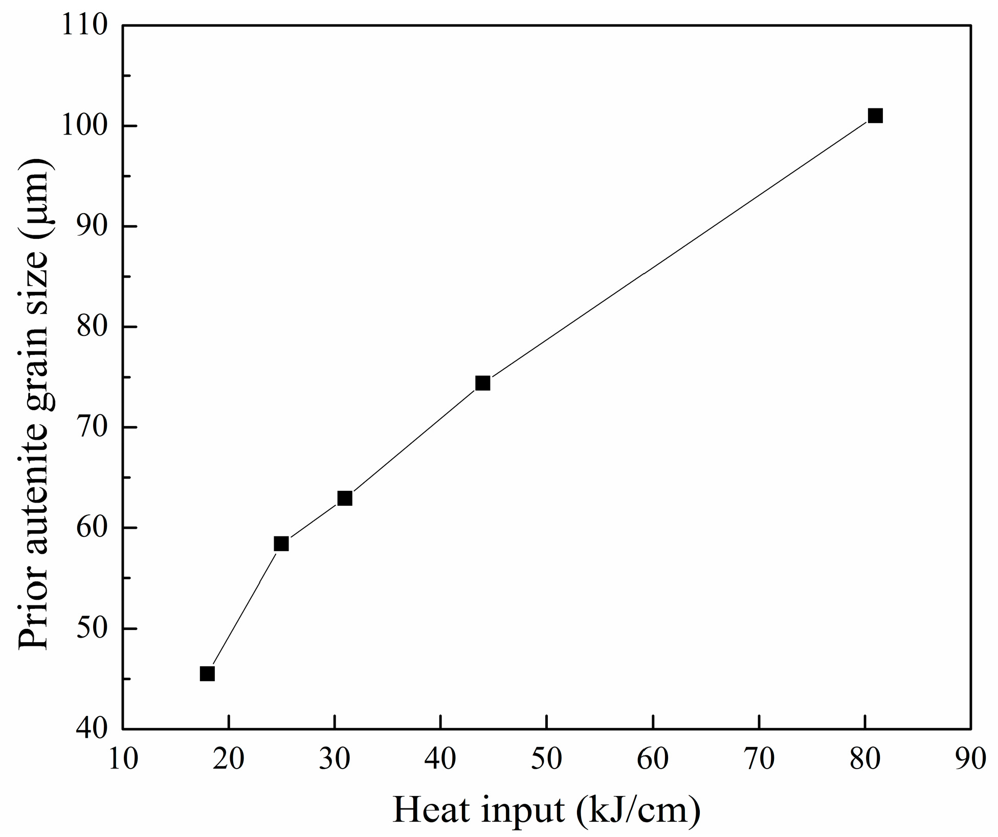
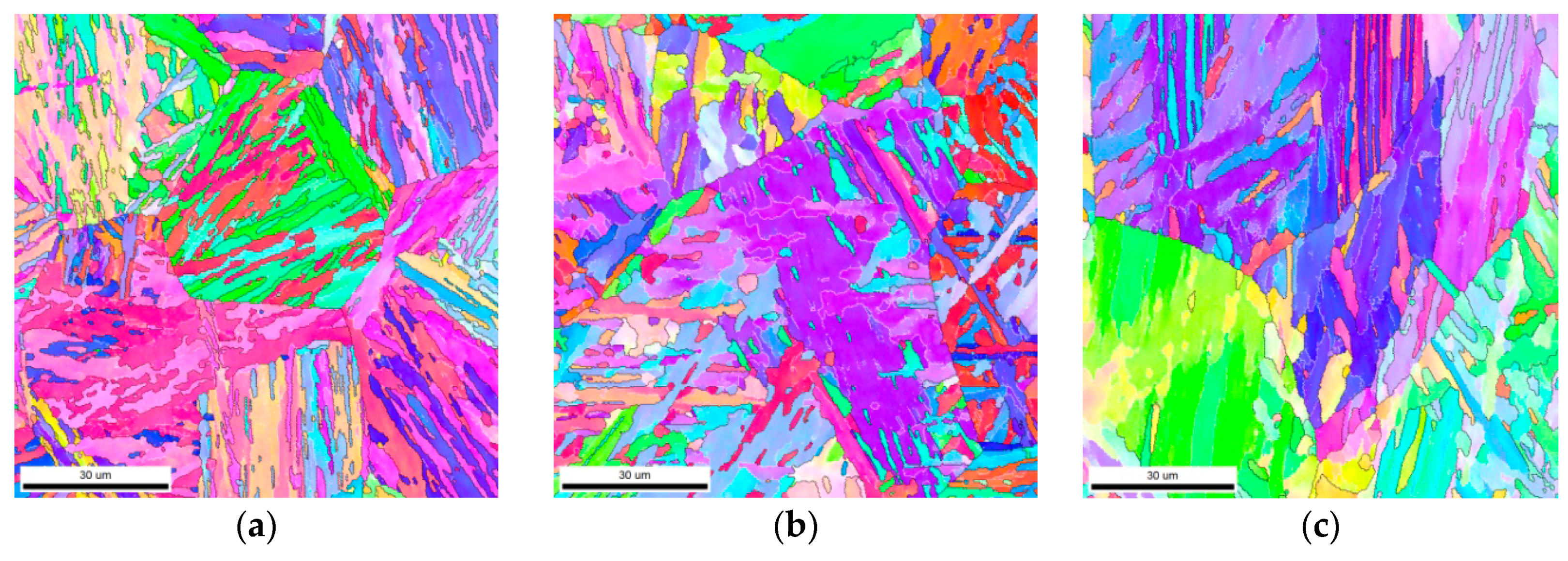
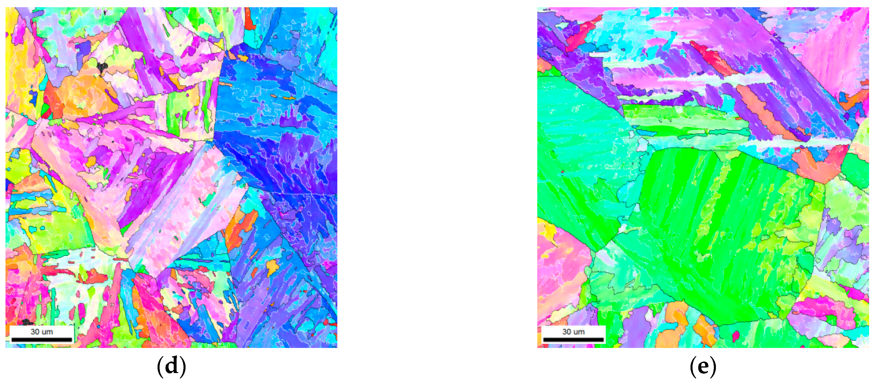
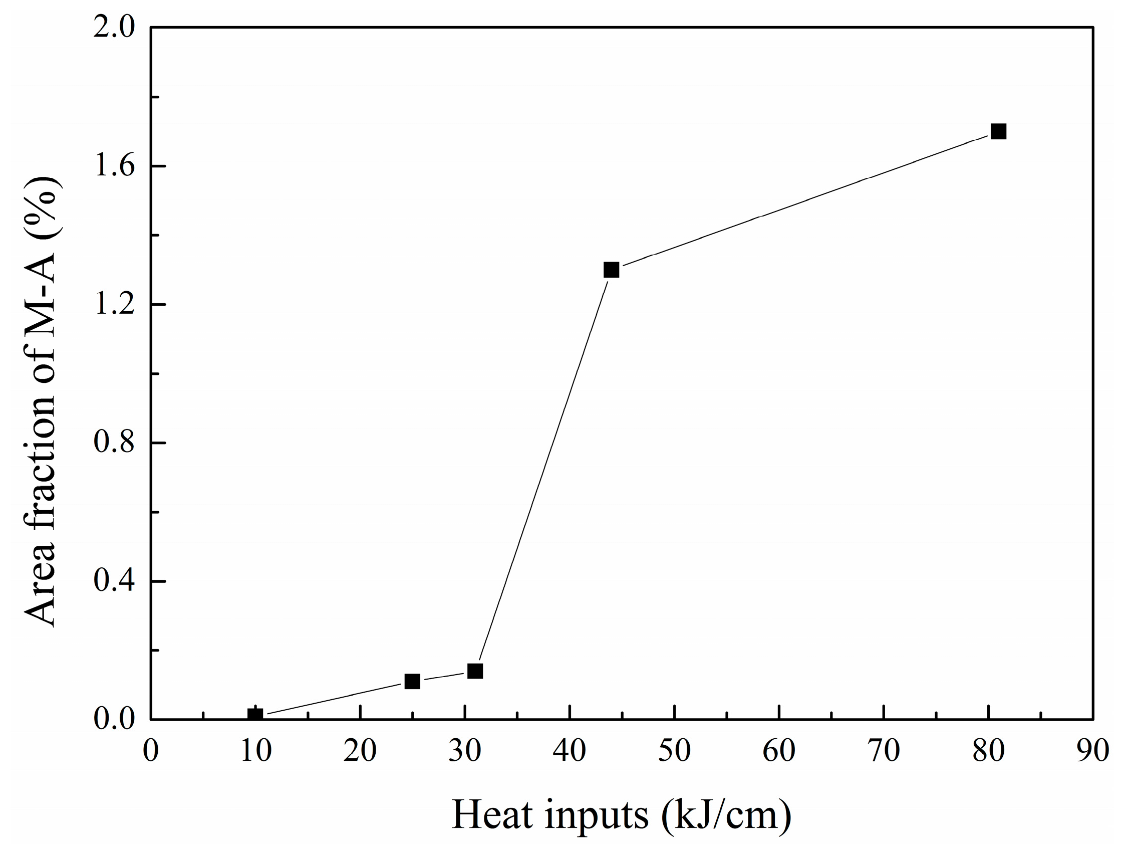
  • At 18 kJ/cm, the microstructures are composed of lath bainite and granular bainite; lath bainite decreases with increasing heat input. The increase in the 50% FATT results mainly from an increase in the austenite grain size and effective grain size, and a decrease in lath bainite and the fraction of HAGBs (misorientation: ≥15°).

Acknowledgments

This work was financially supported by the National Natural Science Foundation of China (Grant No. 51471142 and No. 5167010961).

Author Contributions

Qingfeng Wang and Qingfeng Ding conceived and designed the experiments; Qian Wang performed the experiments; Fucheng Zhang and Zhongran Shi analyzed the data; Tianshang Wang contributed analysis tools; Qingfeng Wang and Qingfeng Ding wrote the paper.

Conflicts of Interest

The authors declare no conflict of interest.

References

  1. Guo, A.; Misra, R.D.K.; Liu, J.; Chen, L.; He, X.; Jansto, S.J. An analysis of the microstructure of the heat-affected zone of an ultra-low carbon and niobium-bearing acicular ferrite steel using EBSD and its relationship to mechanical properties. Mater. Sci. Eng. A 2010, 527, 6440–6448. [Google Scholar] [CrossRef]
  2. Hu, J.; Du, L.-X.; Wang, J.-J.; Gao, C.-R. Effect of welding heat input on microstructures and toughness in simulated CGHAZ of V–N high strength steel. Mater. Sci. Eng. A 2013, 577, 161–168. [Google Scholar] [CrossRef]
  3. Shanmugam, S.; Ramisetti, N.K.; Misra, R.D.K.; Hartmann, J.; Jansto, S.G. Microstructure and high strength-toughness combination of a new 700 MPa Nb-microalloyed pipeline steel. Mater. Sci. Eng. A 2008, 478, 26–37. [Google Scholar] [CrossRef]
  4. Lan, L.; Qiu, C.; Zhao, D.; Gao, X.; Du, L. Analysis of microstructural variation and mechanical behaviors in submerged arc welded joint of high strength low carbon bainitic steel. Mater. Sci. Eng. A 2012, 558, 592–601. [Google Scholar] [CrossRef]
  5. Easterling, K. Cracking and fracture in welds. In Introduction to the Physical Metallurgy of Welding, 2nd ed.; Butterworth-Heinemann: Woburn, MA, USA, 1992; Chapter 4; pp. 191–260. [Google Scholar]
  6. Kumar, S.; Nath, S.K.; Kumar, V. Continuous cooling transformation behavior in the weld coarse grained heat affected zone and mechanical properties of Nb-microalloyed and HY85 steels. Mater. Des. 2016, 90, 177–184. [Google Scholar] [CrossRef]
  7. Lambert-Perlade, A.; Gourgues, A.F.; Besson, J.; Sturel, T.; Pineau, A. Mechanisms and modeling of cleavage fracture in simulated heat-affected zone microstructures of a high-strength low alloy steel. Metall. Mater. Trans. A 2004, 35, 1039–1053. [Google Scholar] [CrossRef]
  8. Guo, B.; Fan, L.; Wang, Q.; Fu, Z.; Wang, Q.; Zhang, F. The Role of the Bainitic Packet in Control of Impact Toughness in a Simulated CGHAZ of X90 Pipeline Steel. Metals 2016, 6, 256. [Google Scholar] [CrossRef]
  9. Kumar, S.; Nath, S.K. Effect of heat input on impact toughness in transition temperature region of weld CGHAZ of a HY 85 steel. J. Mater. Process. Technol. 2016, 236, 216–224. [Google Scholar] [CrossRef]
  10. Cao, R.; Li, J.; Liu, D.S.; Ma, J.Y.; Chen, J.H. Micromechanism of Decrease of Impact Toughness in Coarse-Grain Heat-Affected Zone of HSLA Steel with Increasing Welding Heat Input. Metall. Mater. Trans. A 2015, 46, 2999–3014. [Google Scholar] [CrossRef]
  11. Hwang, B.; Kim, Y.G.; Lee, S.; Kim, Y.M.; Kim, N.J.; Yoo, J.Y. Effective grain size and charpy impact properties of high-toughness X70 pipeline steels. Metall. Mater. Trans. A 2005, 36, 2107–2114. [Google Scholar] [CrossRef]
  12. Díaz-Fuentes, M.; Iza-Mendia, A.; Gutiérrez, I. Analysis of different acicular ferrite microstructures in low-carbon steels by electron backscattered diffraction. Study of their toughness behavior. Metall. Mater. Trans. A 2003, 34, 2505–2516. [Google Scholar] [CrossRef]
  13. Gutiérrez, I. Effect of microstructure on the impact toughness of Nb-microalloyed steel: Generalisation of existing relations from ferrite-pearlite to high strength microstructures. Mater. Sci. Eng. A 2013, 571, 57–67. [Google Scholar] [CrossRef]
  14. Lambert-Perlade, A.; Gourgues, A.F.; Pineau, A. Austenite to bainite phase transformation in the heat-affected zone of a high strength low alloy steel. Acta Mater. 2004, 52, 2337–2348. [Google Scholar] [CrossRef]
  15. Kitahara, H.; Ueji, R.; Tsuji, N.; Minamino, Y. Crystallographic features of lath martensite in low-carbon steel. Acta Mater. 2006, 54, 1279–1288. [Google Scholar] [CrossRef]
  16. Iza-Mendia, A.; Gutierrez, I. Generalization of the existing relations between microstructure and yield stress from ferrite-pearlite to high strength steels. Mater. Sci. Eng.-Struct. Mater. Prop. Microstruct. Process. 2013, 561, 40–51. [Google Scholar] [CrossRef]
  17. Liu, F.; Sommer, F.; Bos, C.; Mittemeijer, E.J. Analysis of solid state phase transformation kinetics: Models and recipes. Int. Mater. Rev. 2007, 52, 193–212. [Google Scholar] [CrossRef]
  18. Liu, Y.; Wang, D.; Sommer, F.; Mittemeijer, E.J. Isothermal austenite-ferrite transformation of Fe-0.04 at % C alloy: Dilatometric measurement and kinetic analysis. Acta Mater. 2008, 56, 3833–3842. [Google Scholar] [CrossRef]
  19. Zhang, Y.Q.; Zhang, H.Q.; Liu, W.M.; Hou, H. Effects of Nb on microstructure and continuous cooling transformation of coarse grain heat-affected zone in 610 MPa class high-strength low-alloy structural steels. Mater. Sci. Eng. A 2009, 499, 182–186. [Google Scholar] [CrossRef]
  20. Takahashi, M. Recent progress: Kinetics of the bainite transformation in steels. Curr. Opin. Solid State Mater. Sci. 2004, 8, 213–217. [Google Scholar] [CrossRef]
Figure 1. The microstructure of the experimental steel.
Metals 07 00115 g001
Figure 2. The curve of thermal cycle of different heat input.
Metals 07 00115 g002
Figure 3. The tangent method used to determine the transformation temperature.
Metals 07 00115 g003
Figure 4. Effect of t8/5 on the onset and end temperatures for continuous cooling transformation occurring in the simulated CGHAZ.
Metals 07 00115 g004
Figure 5. Simulated CGHAZ microstructure of experimental steel at different t8/5: (a) 10 s; (b) 20 s; (c) 40 s; and (d) 200 s.
Metals 07 00115 g005
Figure 6. Simulated CGHAZ microstructure/prior austenite grain of the experimental steels: (a,b) 18 kJ/cm; (c,d) 25 kJ/cm; (e,f) 31 kJ/cm; (g,h) 44 kJ/cm; and (i,k) 81 kJ/cm.
Metals 07 00115 g006aMetals 07 00115 g006b
Figure 7. Prior austenite grain size at different heat input.
Metals 07 00115 g007
Figure 8. EBSD orientation images with grain boundaries color coded according to the magnitude of the misoriention: (a) 18 kJ/cm; (b) 25 kJ/cm; (c) 31 kJ/cm; (d) 44 kJ/cm; and (e) 81 kJ/cm.
Metals 07 00115 g008aMetals 07 00115 g008b
Figure 9. (a) Frequency of high angle grain boundaries (misorientation: ≥15°); and (b) EBSD-determined mean effective grain size (for tolerance angles of 2–15°) as a function of the heat input.
Metals 07 00115 g009
Figure 10. M-A morphology of the simulated CGHAZ at different heat input: (a) 18 kJ/cm; (b) 25 kJ/cm; (c) 31 kJ/cm; (d) 44 kJ/cm; and (e) 81 kJ/cm.
Metals 07 00115 g010
Figure 11. Area fraction of M-A at different heat input.
Metals 07 00115 g011
Figure 12. TEM micrographs showing microstructure of experimental steels in the simulated CGHAZ. (a,b) 18 kJ/cm; (c,d) 25 kJ/cm; (e,f) 44 kJ/cm; and (gj) 81 kJ/cm.
Metals 07 00115 g012aMetals 07 00115 g012b
Figure 13. Hardness of the simulated CGHAZ at different heat input.
Metals 07 00115 g013
Figure 14. The impact toughness at −20 °C and 50% FATT curve of the simulated CGHAZ in the experimental steels subjected to different heat inputs. (a) Impact toughness at −20 °C; and (b) 50% FATT.
Metals 07 00115 g014
Figure 15. SEM micrographs showing surface morphologies resulting from impact fracture at −20 °C of samples with different heat inputs of (a) 18 kJ/cm; (b) 25 kJ/cm; and (c) 81 kJ/cm.
Metals 07 00115 g015
Figure 16. The effective grain size of the simulated CGHAZ at different heat input.
Metals 07 00115 g016
Table 1. Chemical composition of the experimental steel (wt %).
CMnSiCuNi + Cr + MoNb + V + TiB
0.091.500.300.201.150.0830.0011

