Article

Characterization of the Microstructure, Mechanical Properties, and Corrosion Resistance of a Friction-Stir-Welded Joint of Hyper Duplex Stainless Steel

1
College of Materials Science and Engineering, Taiyuan University of Technology, Taiyuan 030024, China
2
Taiyuan Iron and Steel (Group) Company Ltd., Taiyuan 030003, China
*
Author to whom correspondence should be addressed.
Metals 2017, 7(4), 138; https://doi.org/10.3390/met7040138
Submission received: 10 January 2017 / Revised: 31 March 2017 / Accepted: 5 April 2017 / Published: 13 April 2017
(This article belongs to the Special Issue Alloy Steels)

Abstract

:
This study investigates the microstructure, mechanical properties, and corrosion resistance of a friction-stir-welded joint of the hyper duplex stainless steel SAF2707. Friction stir welding (FSW) is performed at a tool rotation rate of 400 rpm and a welding speed of 100 mm/min. The microstructure of the joints is examined using scanning electron microscopy and X-ray diffraction. Tensile test and fractography are subsequently employed to evaluate the mechanical properties of the joints. Results show that the grain size of the stir zone (SZ) is smaller than that of the base metal (BM). Electron back-scattered diffraction analysis reveals that fine-equiaxed grains form in the SZ because of the dynamic recrystallization during the FSW. These grains become increasingly pronounced in the austenite phase. The tensile specimens consistently fail in the BM, implying that the welded joint is an overmatch to the BM. Moreover, the welded joints consist of finer grains and thus display higher tensile strength than their BMs. Potentiodynamic polarization curves and impedance spectroscopy both demonstrate that the corrosion resistance of the SZ is superior to that of the base material.

1. Introduction

Given the favorable combination of mechanical and corrosion properties and excellent weldability of duplex stainless steels (DSSs), DSSs have become more attractive than austenitic and ferritic stainless steels in terms of applications [1,2]. In the process of their development, super stainless steels have been widely applied in environments characterized by relatively excessive corrosion and high pressure. However, they exhibit incapacities because of the short service life in such areas as oil exploration, which strives for deeper water over 2500 m and requires stronger corrosion resistant [3]. Thus, a new high-alloyed DSS demonstrating excellent corrosion resistance and enhanced strength is necessary. SAF2707HD is a new type of DSS in the form of a hyper stainless steel developed by Sandvik Corporation. It exhibits excellent performance in relevant test evaluations. The superior corrosion resistance of DSSs extends their application to aggressive chloride environments, such as hot tropical seawater, seabed piping systems, and deep wells [3,4]. The corrosion resistance of DSSs is determined by the fraction of α, γ, and detrimental intermetallic phases, such as σ, which often renders Cr- and Mo-depleted zones susceptible to high-rate dissolution [5,6,7]. Given their inherent brittleness, these undesirable intermetallic phases, which easily form during hot rolling or welding, often degrade the mechanical properties of DSSs [8,9].
In most applications, selected construction materials must undergo a welding process. However, problems can occur when welding DSSs [10]. For example, fusion welding may destroy the favorable duplex microstructure of DSSs and produce coarse ferrite grains, intergranular brittle and intergranular austenite phases in the weld metal and heat-affected zone [11]. In addition, high ferrite content and coarse grains reduce the corrosion resistance and mechanical properties of welded joints [12,13]. Moreover, σ phase in DSSs may precipitate during welding because of high Cr, Mo, and N concentrations. Studies have shown that the holding time of precipitating 1% σ phase at the most critical temperature is 134 s, whereas that for hyper DSS (HDSS) is 69 s [14,15].
Several welding methods have been used to address these problems. Among these methods, friction stir welding (FSW) has recently attracted considerable attention. FSW is a solid-state technology wherein a material is subjected to intense plastic deformation at an elevated temperature, thereby generating fine and equiaxed recrystallized grains. The main advantages of FSW are solid-state welding, absence of metal addition, and fast cooling. In addition, FSW prevents precipitation. Initially, FSW is mainly used in metals with low-melting points, such as Al and Mg alloys, because the tools used in FSW display limited capacities at high temperatures [16,17]. With the improvement in tools used in FSW, the application of FSW is extended to materials with high melting points, such as steel and titanium alloys. As a result, numerous investigations have been conducted on FSW of steels and other alloys with high melting points.
Existing investigations report that only a few studies have explored the effect of FSW on the microstructure, mechanical properties, and corrosion properties of DSSs [18,19,20]. Sato [18] has demonstrated that FSW elicits the desirable mechanical properties of SAF2507; these properties include defect-free weld and generation of fine and equiaxed recrystallized grains in the stir zone (SZ). Saeid [19] has investigated the mechanism of the grain refinement of DSSs by using electron backscattered diffraction (EBSD) and found that the mechanism is correlated with different mechanisms of dynamic recrystallization. Furthermore, the corrosive behavior of lean DSSs subjected to FSW was studied by Sarlak, who found that the resistance of DSSs to the local and pitting corrosion of weldments is superior to that of base metals (BMs) [20].
Studies have shown that FSW considerably affects the mechanical properties and corrosion resistance of DSSs during welding. However, to the best of our knowledge, studies on the welding of HDSS using FSW are few. Studies on HDSS welding mainly focus on the influence of shielding gases on corrosion resistance [21,22]. No systematic research has investigated the corrosion resistance and mechanical properties of HDSS weldments. Therefore, in this study, HDSS is welded using FSW to investigate the microstructure, mechanical properties, and resistance to corrosion of HDSSs that underwent FSW.

2. Materials & Experiment

SAF2707HD was prepared using vacuum induction furnace and electro-slag remelting furnace. Table 1 shows the chemical composition of SAF2707HD. The experimental steel was supplied in the form of a cold rolled and annealed (1200 °C for 1 h) plate (150 mm × 100 mm × 3 mm). The plates were ground to remove the oxide on the top and bottom surfaces to ensure the welding quality. Welding was performed using an FSW machine (China FSW Center, Beijing, China) parallel to the rolling direction at a welding speed of 100 mm/min and a tool rotation rate of 400 rpm. The welding tool was made of tungsten-rhenium (W-RE) with a shoulder diameter of 20 mm and a tapered probe. The pin was tapered from 8 mm at the shoulder to 4.5 mm with a length of 2.8 mm. Figure 1 presents the schematic of the tool used in the FSW experiment. During the welding process, the tilt angle was 0° and downward force was controlled at 20 kN. An argon atmosphere around the tool was introduced as shielding gas to prevent excessive surface oxidation. Figure 2 presents a typical surface morphology diagram of SAF2707HD butt joint subjected to FSW. In this diagram, the welding surface is smooth, and macroscopic cracks, air holes, and tunnel defects are absent along the welding line, indicating that the welding parameter can produce sufficient heat input to ensure the flow of plastic materials.
Following FSW, a metallographic examination was conducted on a transverse section of the welded joint via optical microscopy (OM) (Leica, Heerbrugg, Switzerland) and scanning electron microscopy (SEM) (FEI, Hillsboro, OR, USA) equipped with an INCA energy dispersive X-ray spectrometer system (EDX) (Oxford Instruments, Oxon, UK). The specimen for OM was chemically etched with 25 g of KOH, 15 g of KSCN, and 100 mL of distilled water at a temperature of approximately 65 °C. Prior to EBSD, the specimen was electrolytically polished using 8 mL of perchloricacid, 5 mL of glycerol, 100 mL of ethanol, 10 mL of 2-butoxy ethanol, and 15 mL of distilled water at room temperature. Electrolytic polishing was performed at 30 V and at a 15 s storage time, respectively. A Philips X-Ray diffractometer (Philips, Eindhoven, Netherlands) was used to identify the phase formed on the surface of the SZ during the FSW.
Mechanical properties were investigated mainly through Vickers hardness and tensile tests. The tensile test was conducted at ambient temperature on an Instron testing machine (Instron, Boston, MA, USA). Vickers hardness test was performed using a LECO LM-700ATV hardness testing machine (LECO, St. Joseph, UT, USA). The hardness profiles were measured along and perpendicular to the mid-thickness of the joint with regular intervals of 0.5 mm at a load of 50 g for 15 s. The samples used in the tensile test were the welded joints extracted from the weldments. Figure 3 shows the sizes of tensile sample of the welded joints. The loading force was perpendicular to the direction of the welding at a constant cross head speed of 1 mm/s. The tensile section fracture was observed through SEM.
A three-electrode electrochemical cell system was introduced to assess the electrochemical corrosion of the BM and welded joints. A three-electrode system comprises a working electrode, platinum (Pt) foil, and a saturated calomel electrode (SCE). A Pt electrode and SCE work as counter and reference electrodes, respectively. All potentials quoted were related to SCE. The BM and weldment acting as working electrodes were sealed with fastening screws and then combined with a seal ring to avoid crevice corrosion. The exposed electrode area was 1 cm2. All measurements were performed three times to ensure their accuracy and repeatability. Potentiodynamic polarization curves were obtained in 3.5 wt. % NaCl solution at 25 °C ± 1 °C at a scanning rate of 0.5 mV/s. The scanning region was from −0.2 V to a certain current at which transpassivity occurred.
Electrochemical impedance spectroscopy (EIS) (Princeton Applied Research, Oak Ridge, TN, USA) was conducted to evaluate the electrochemical behavior of the oxide film formed on the surface of the stainless steel. Prior to all the experiments, the specimens were immersed in a test solution for 30 min to reach a stationary condition. The scanning frequency region ranges from 0.1 mHz to 100,000 Hz. The measured EIS data was fitted with Zview 2.70 (Scribner Associates, Southern Pines, NC, USA).

3. Results and Discussion

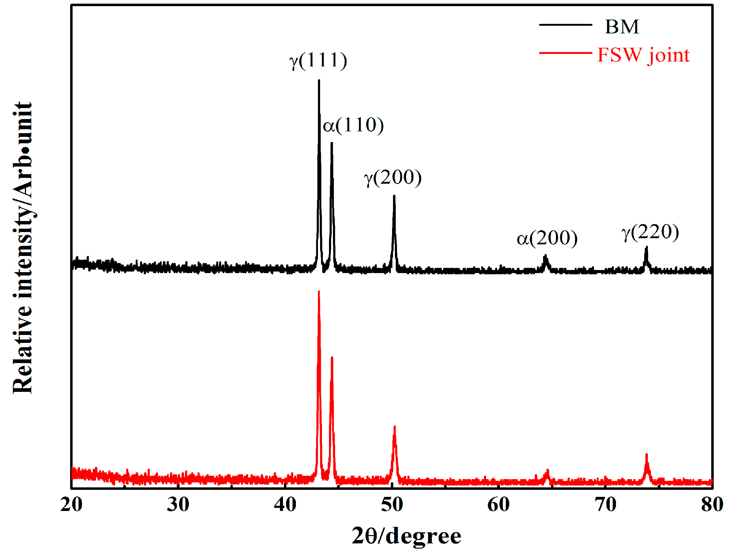
3.1. Microstructural Evolution

Figure 4 shows a typical low-magnification overview of the different sections of SAF2707 welded joint subjected to FSW. The joint without internal defects exhibits a high degree of community. In the cross section (Figure 4a), the left and right sides of the joint center comprise the retreating side and advancing side of the rotational tool, respectively. A welded joint can be divided into three zones: the SZ, the thermo-mechanically affected zone (TMAZ), and the BM. Additionally, the figure shows that the SZ is characteristic of a ring vortex, which is produced through the flow of materials driven by the thread on the pin. A similar microstructural characterization is performed in related studies [24,25]. Based on the advancing and retreating sides of the working tool, the TMAZ located adjacent to the SZ can be classified into TMAZ–AS and TMAZ–RS. As verified by other authors [18,19,20,24], no obvious heat affected zone is observed because of the relatively low heat input..
Figure 4b shows the schematic of microstructure of the as-received BM. The BM exhibits a microstructure of austenitic islands embedded in ferrite matrix. Figure 4c–f shows the microstructures at different joint positions. As shown in Figure 4c, the SZ located in the joint center displays a stretched and two-phase microstructure. Compared with BMs, the SZ contains more elongated and finer austenitic islands. Similar to the typical microstructure of Al alloy and steel joints welded through FSW [16,17,24,25,26,27], the average grain size is significantly finer in the SZ than in the BM because the SZ experiences higher temperature and has undergone significantly plastic deformation. No significantly grain coarsening and σ phase are observed across the welded joint. During FSW, the material hardly melts because of the low peak temperature. These factors possibly account for the absence of grain coarsening and σ phase across the welded joint. Moreover, the region in the SZ adjacent to the TMAZ-AS (Figure 4d) consists of the finest equiaxed grains. As explained by Liu [26], the material lying in the advancing side of the SZ is slightly displaced forward from its original position. The material is rotated using a pin tool and deposited at roughly the same location as its initial position. The material flow of FSW suggests that the material on the advancing side of the SZ rotates and advances with the tool, and the material on the retreating side is entrained, indicating a relatively small deformation [27]. This mechanism of material flow suggests that the material in the SZ at the advancing side undergoes the most severe deformation and has a tendency to disrupt a duplex microstructure that produces the finest grains.
As shown in Figure 4e,f, the TMAZ–AS/SZ boundary is clearly sharper in the advancing side than that on the retreating side. This result is consistent with previous findings [18,24]. The difference between these boundaries can be attributed to the difference in shear stress between the advancing and retreating sides of the working tool. The shear force of the advancing side of the tool induces a larger plastic deformation than that induced in the retreating side. One study [18] has shown that the advancing side experiences the most severe deformation because of the material flow mechanism induced by the difference in plastic deformation around the pin tool during the FSW process. The TMAZ microstructure is distorted, and its grains are re-oriented perpendicular to the rotational direction of the tool. The asymmetry of FSW is evident in the TMAZ–AS and TMAZ–RS microstructures.
Figure 5 shows the backscatter electron (BSE) images of the SZ in different positions after electrolytic polishing. The grain size distribution is inhomogeneous along the thickness direction of the welded joint. The grain size decreases gradually from the top surface to the bottom of the welded joint. The heat during welding process is generated by the friction between the rotating tool and material interface, and the contact between the tool shoulder and the sample surface generates most of the heat; thus, the maximum temperature should be observed near the top surface. Moreover, given that the bottom of the testing plate comes in contact with the metal operating platform and that the rate of heat dissipation is faster, the cooling rate near the bottom is higher than that at the top surface. Grain size along the thickness direction may be attributed to the graded distribution of the peak temperature and to the varying cooling rates. The high peak temperature and slow cooling rate are regarded as being indicative of the remarkable growth of grains near the top surface.
Figure 6 shows the EBSD maps of the BM and SZ. The result of the EBSD analysis on the BM reveals an austenite phase, which uses a higher number of grains (mostly twin boundaries) than the ferrite phase. The average grain sizes of the austenite and ferrite phases are 9 and 9.5 μm, respectively. The SZ displays fine and equiaxed grain microstructures. The average grain size of the austenite phase in the SZ is approximately 1.6 μm, which is smaller than that in the ferrite phase (2.2 μm). The amounts of twin grains are considerably lower than those of the BM, suggesting that the intense deformation associated with FSW disintegrates the initial annealed microstructure of BMs. The duplex phase of the SZ is finer than that of the BM. The grain size difference between the SZ and the BM, as observed in the microstructure and EBSD maps, suggests that dynamic recrystallization (DRX) occurs in the austenite and ferrite phases during FSW. As reported in related studies on the FSW, microstructures in the SZ experiences severe deformation and high temperature; thus, DRX leads to fine grains [18,19,20,24,25,26].
In the SZ, grain size in the austenite and ferrite phases slightly differ; that is, the austenite phase is slightly more pronounced than the ferrite phase. The grain size of DRX is known to be associated with the deformation and diffusion rate of atoms. During FSW, deformation mainly occurs in the ferrite phase because it is considerably weak at high temperatures. Fang et al. have demonstrated that, during the hot deformation of a new DSS containing high nitrogen content, the wedge crack is nucleated at the interface between the ferrite and austenite phases and easily propagates toward the ferrite phase; hence, the ferrite phase is softer than the austenite phase at high temperatures [28]. Consequently, great strain occurs in the ferrite phase and supplies additional energy for nucleation. Moreover, the ferrite phase has a higher diffusion rate of atoms compared with the austenite phase at high temperatures [28]. Both of them can produce a recrystallization process, which is followed by grain growth in the ferrite phase. According to earlier studies, DRX, including continuous DRX (CDRX), or discontinuous DRX (DDRX) may exist in the SZ during the FSW of DSSs [24,25,26,29,30]. High stacking fault energy (SFE) of the ferrite phase facilitates CDRX. By contrast, low SFE of the austenite phase facilitates DDRX.
Based on a simple mode of heat generation during FSW described by Schmidt [31], maximum heat is generated in interfaces of shoulder and plate. SAF2707HD is a high-alloyed steel, and the precipitation rate of the σ phase is generally fast. XRD was used to identify the different phases based on their locations in the XRD pattern. Additionally, XRD was used to clearly understand whether σ phase occurs on SZ. Figure 7 shows the XRD profile of the SZ surface. The ferrite and austenite phases are readily observed in the XRD pattern, and their corresponding diffraction peaks are marked. The σ phase was not formed during the FSW process, or its amount is so low that it cannot be detected via XRD. Although the introduction of high strain and DRX can promote a mutual diffusion of alloying elements [32], the time for nucleation of the σ phase is insufficient because of a short welding thermal cycle.
During solid-state transition, austenite formation in the fusion zone of DSSs depends on cooling rate. Followed by a fully ferrite phase, nucleation of the austenite phase preferentially lies in the grain boundaries of the ferrite grains during the weld cooling cycle. Previous evidence demonstrates that using high-heat inputs and slow cooling rates during the GTA process produce microstructures containing considerable amounts of various forms of the austenite phase, such as grain boundary austenite and secondary austenite [33]. In the present study, microstructural characterization shows that the intergranular austenite phase is absent in all regions across the weld. In addition, these regions contained a microstructure consisting of a ferrite matrix with austenite islands. As shown in Figure 7, the XRD spectra of the BM and the SZ consist of ferrite and austenite phases. The intensities of the α phase diffraction peak (110) and γ phase diffraction peak (111) in the SZ and the BM are nearly equal, implying that the ratio of the ferrite/austenite phase of the SZ is close to that of the BM. Overall, the ratio of the ferrite/austenite phase in the SZ is similar to that in the BM, as revealed by related studies [18,24]. The similarity of the ratios of the ferrite/austenite phase between SZ and BM indicates that the peak temperature is below the transition temperature between austenite and ferrite during FSW of DSSs.

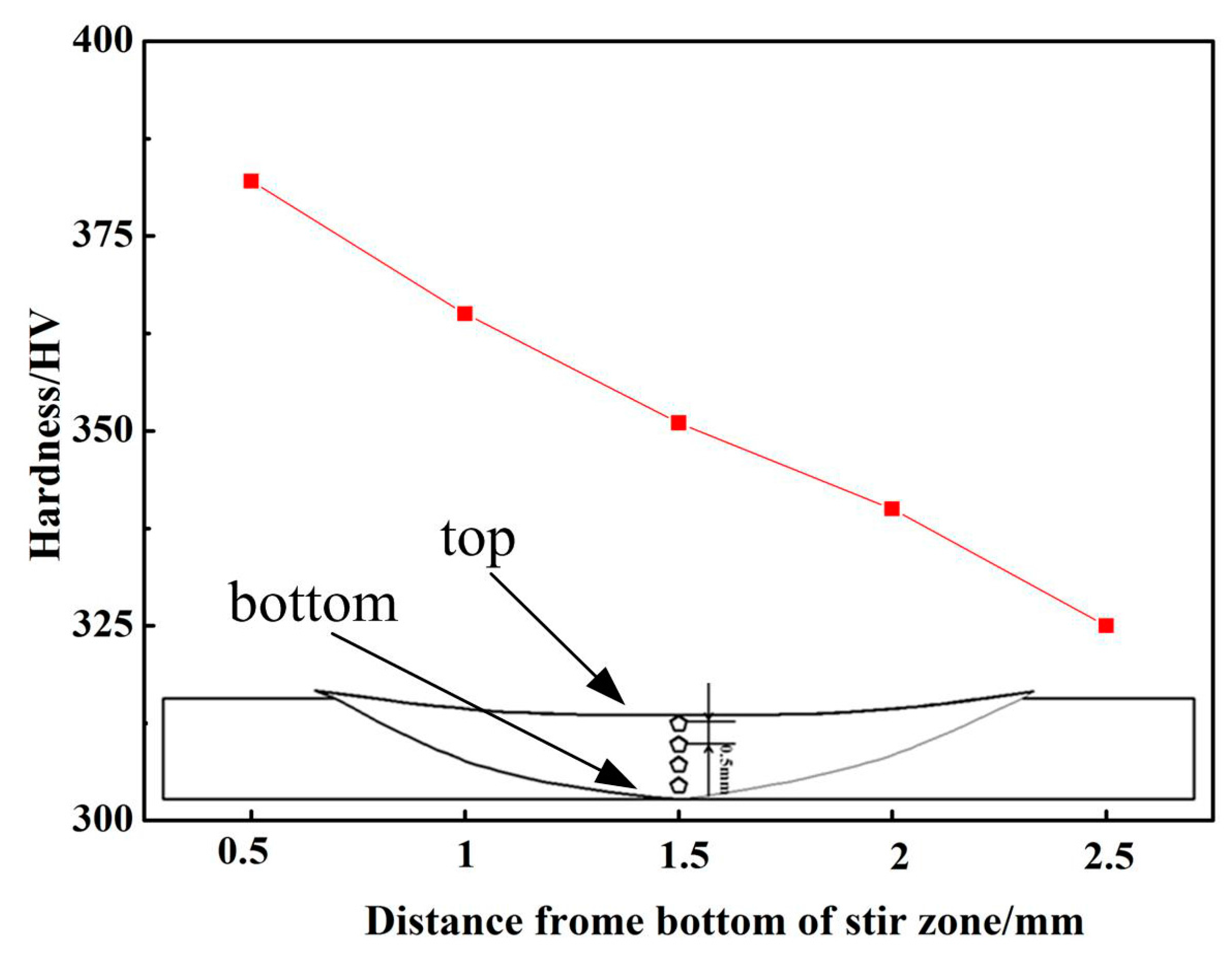
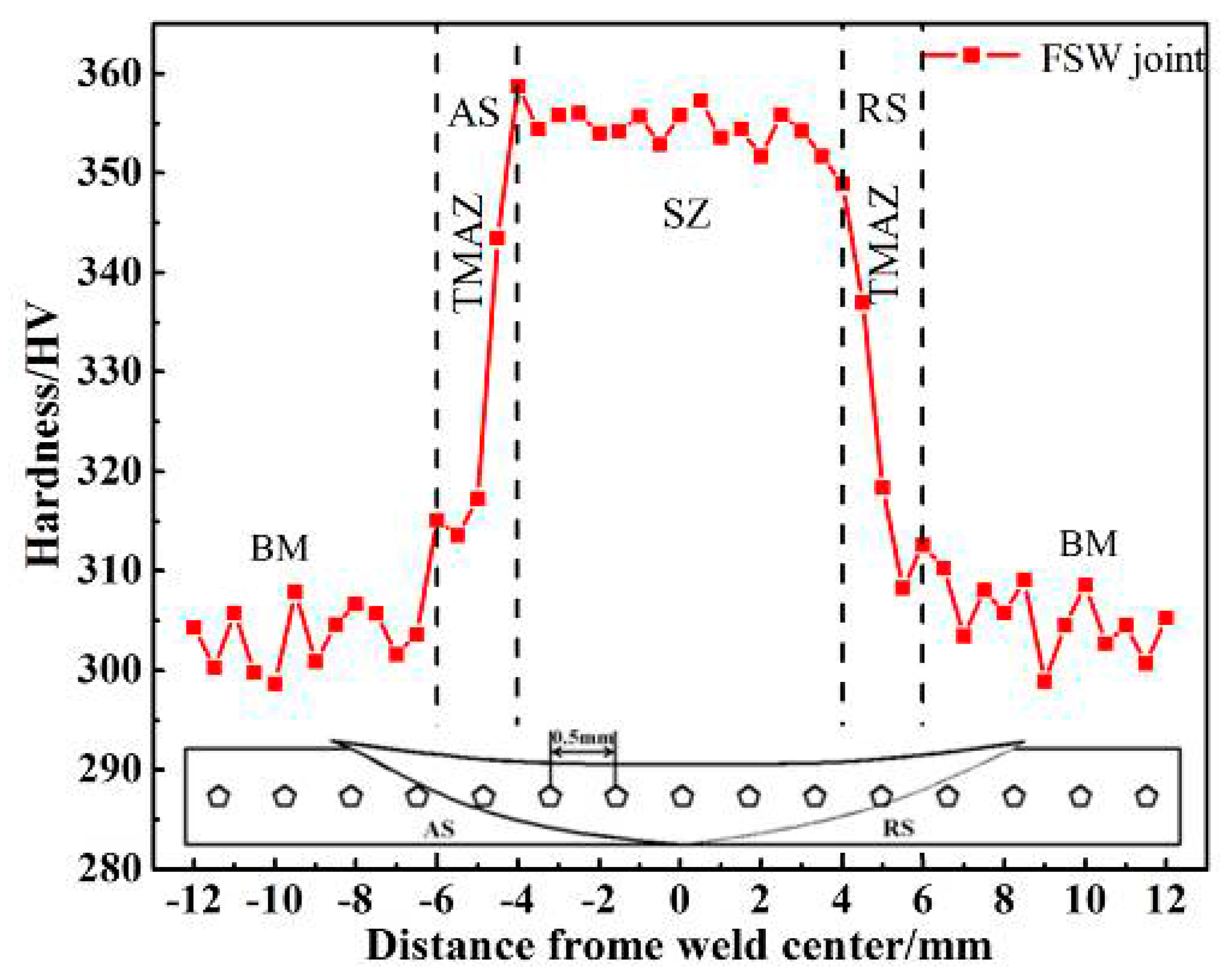
3.2. Mechanical Characterization

Figure 8 shows the hardness values, as a function of the distance from the weld center, across the joint. The maximum hardness with minimal fluctuation lies in the SZ. Compared with the BM, the SZ shows a smaller fluctuation. BMs contain large grains, and the hardness of its ferrite and austenite phases differs. Thus, fluctuation in the BM is greater than that of the SZ. As the distance from the SZ increases, the hardness values gradually decrease. The difference in hardness between the BM to the TMAZ ranges from 303 HV to 355 HV. The main mechanism of this remarkable welding technique involves fine grains occurring in the SZ as a result of DRX without changes in proper phase balance. Moreover, as indicated by the microstructure of the SZ, the σ phase precipitation has not occurred. Hence, as explained by Hajian [34], the dominant mode toward an increase in hardness in the SZ is related to grain refinement, according to the fine-grain strengthening theory. Similarly, the values of hardness gradually decrease from the bottom to the surface of the weld joint (shown in Figure 9).
Figure 10a,b shows the stress–strain curves and transverse tensile properties of the BM and FSW HDSS weld joint. The experimental result shows that the 0.2% offset yield and ultimate tensile strength of the weld metal overmatch those of the BM, consistent with the Vickers hardness results. According to fine-grain strengthening theory, the elevated strength of the weldment relative to that of the BM is consistent with the results of microstructural observation. As reported by Esmailzadeh [30], owing to the presence of fine grains in SZs, the strength of welded SZ joints is more elevated than that of BMs. Fine grains accompanied by additional grain boundaries inhibit dislocation motion, thereby increasing the strength. The failure is consistently located in the BM and far from the FSW joint (Figure 11), indicating that the BM is weaker than the FSW joint. The tensile test results show that FSW produces defect-free HDSS welds. However, elongation of the FSW joint is 30%, which is lower than that of the BM, and their difference is 6%. Li [35] explained that severe plastic deformation in the SZ reduces ductility because of high-density dislocations generated in the SZ. Plastic deformation mainly occurs on the base metal, implying that the strength of the weldments is influenced by the FSW joint.
Figure 12a,b shows the optical micrograph of the tensile surface and SEM morphology of the weldment fracture surface. The phase appearing reddish brown in the OM is the ferrite phase (α) and the phase appearing white is the austenite phase (γ). The typical EDX results of dual phases are shown in Figure 12c,d, respectively. Crack initiation apparently occurred in the interface of the ferrite and austenite phases. The cracks propagated toward the austenite phase, which is softer than the ferrite phase at room temperature as a result of the low SFE. The SEM morphology of the weldment fracture surface is characterized by a dimple with a microvoid, a feature of a ductile fracture. However, size distribution of the dimple is inhomogeneous, which corresponds to low elongation [35].

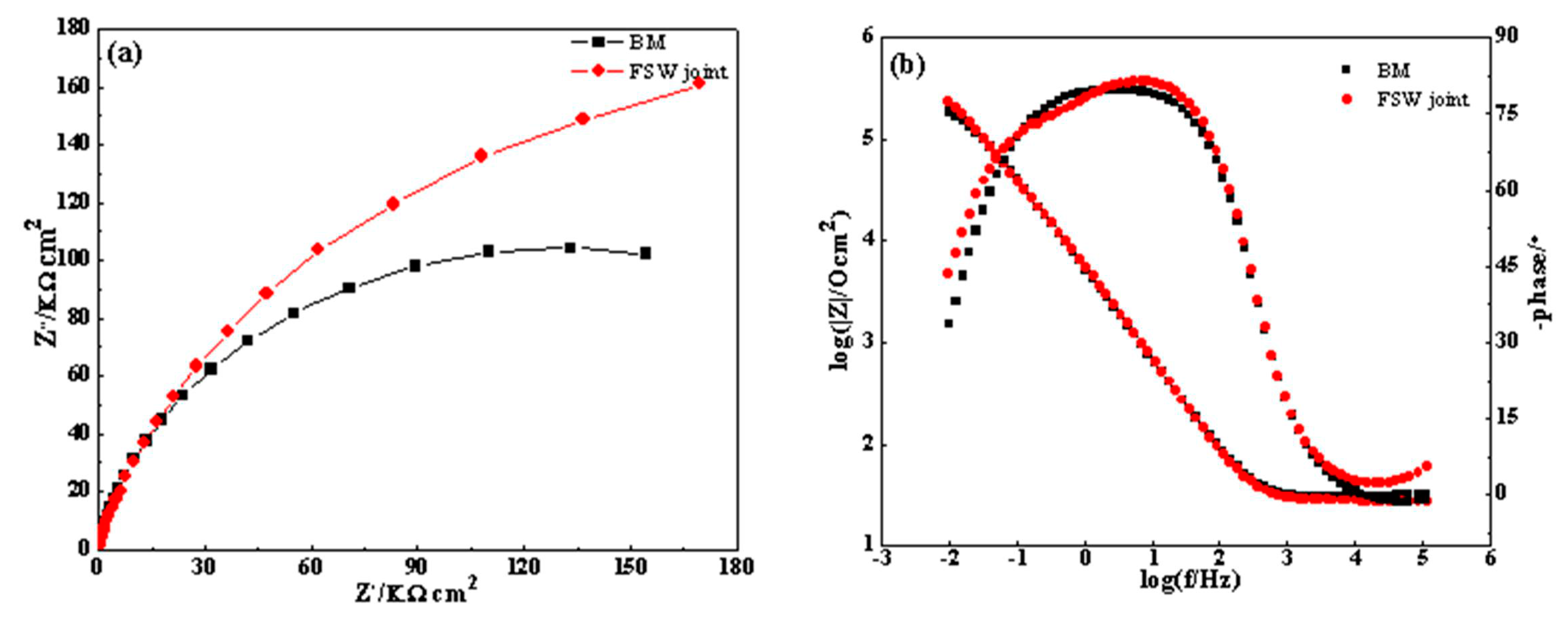
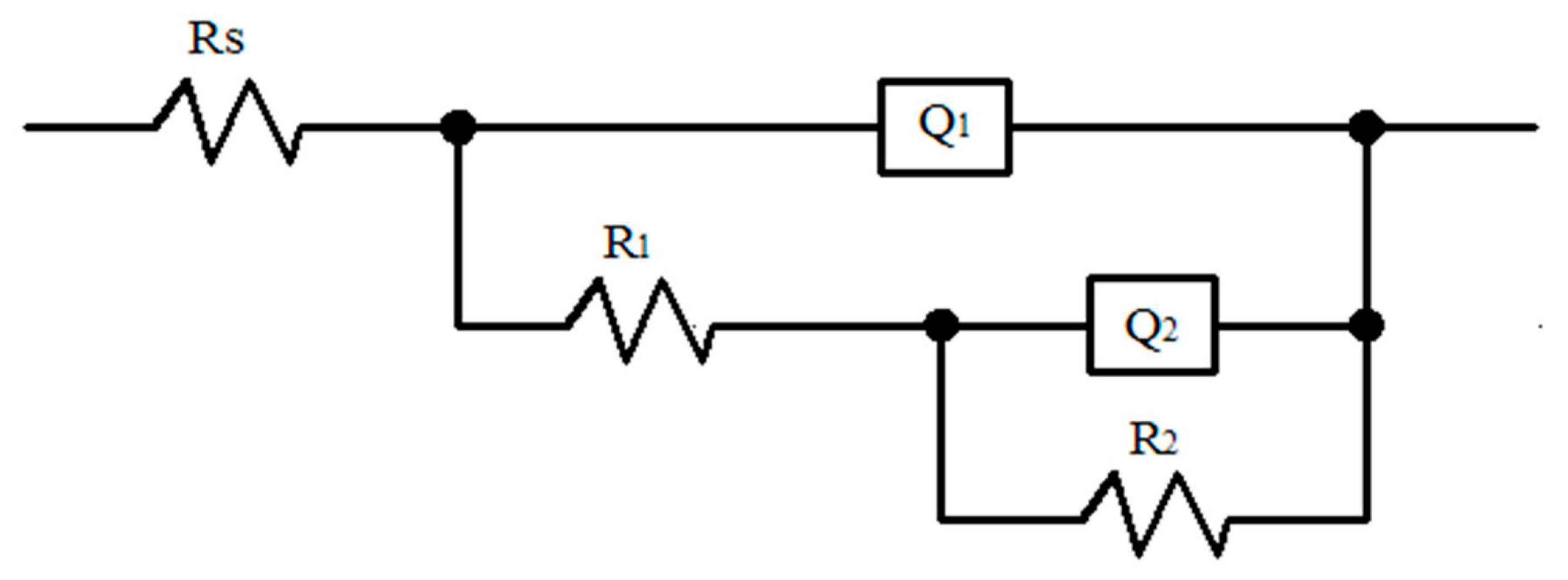
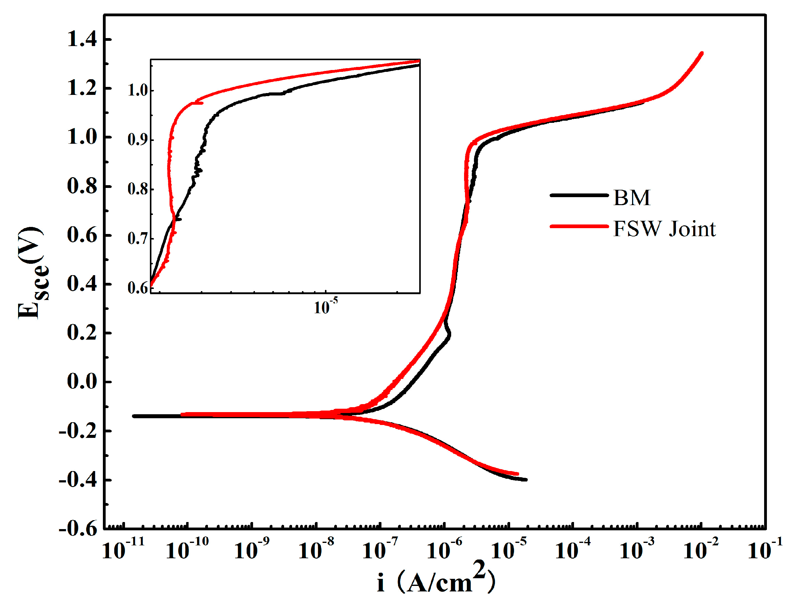
3.3. Corrosion Resistance

The effect of FSW on corrosion resistance of the SZ was investigated in a 3.5% NaCl solution at 25 °C ± 1 °C (Figure 13). The polarization curves of the BM and the SZ appear to have similar shapes and contain a wide passive region around 1.2 V. The pitting potentials of the BM and the SZ are 0.95 and 0.98 Vsce, respectively. The difference in corrosion resistance between the pitting potential (Epit) and passive current density (ipass) is positive. That is, the SZ displays a greater corrosion resistance than the BM. In addition, the magnitude of variation in corrosion potential (Ecorr) corresponds to the pitting potential. Along with the mechanism of the FSW, fine grains are generated in the SZ. A large number of grain boundaries exhibit active positions susceptible to corrosion. They also supply ionic conduction channels contributing to anodic reactions. Ralston [36] has demonstrated that materials with fine grain structures are expected to be more corrosion resistant. The improved corrosion resistance can be attributed to the fine grains in the SZ; that is, an increase in the grain boundary density surface acting as diffusion paths of atoms facilitates passive film growth. Similar results have been reported [20,37]. As reported by LvJinlong [37], fine grains strengthen the stability and uniformity and improve the corrosion resistance of passive films of 2205 duplex stainless steels. Another study has demonstrated that the fine grains achieved by FSW increases the corrosion resistance of DSSs [20].
The electrochemical properties of the passive film were evaluated via EIS, a technique for accessing relaxation phenomena. Figure 14a shows the typical Nyquist plots of base and weld metals in 3.5% NaCl. Two successive depressed semicircles appear in the Nyquist plot. The diameter of the capacitive semicircle in the Nyquist diagrams is correlated with corrosion resistance. Thus, the numerical size of the charge transfer resistance of the passive film is reflected [38]. The weldment has a larger impedance diameter than the BM, indicating superior corrosion resistance of the former. Figure 14b shows the corresponding Bode plots of the BM and the SZ. Two well-defined time constants are observed in the two Bode-phase formats. This observation indicates that a passive film has formed on the 2707 HDSS surface and it consists of a bilayer structure. As reported [37,38], a passive film, including its active or passive region, cannot be ideally homogeneous.
An equivalent circuit (EC) has been proposed to be used to interpret the interface phenomenon between an electrode and a sample [37,38,39]. The maximal phase angle value in both Bode-phase plots is lower than 90°. Such behavior can be attributed to the deviation from the ideal capacitor behavior. Therefore, constant phase elements (CPEs) instead of a pure capacitance are used in EC to describe the frequency-independent phase shift betweenalternating potential and its current response. The corresponding impedance of a CPE is defined by the expression ZCPE = Z0(jw)n. n, which is a CPE exponent, describes the deviation from the ideal capacitance. When n = 1, the CPE represents an ideal capacitance. For 0.5 < n < 1, n decreases with the increase in capacitance dispersion. When n = 0.5, the CPE symbolizes a Warburg impedance characteristic of diffusion.
Figure 15 shows the EC proposed to model the electrode/sample interface. This circuit contains two time constants that match well the experimental results. Rs is the resistance of the solution. Q1 represents the capacitive behavior of the passive film resulting from the formation of the ionic paths across the passive film, and constitutes the first time constant laid at a high frequency coupled with a resistance R1. R1 is the ionic diffusion resistance of the outer passive film. The second time constant is located in the low frequency region comprising Q2 and R2. Q2 symbolizes the capacitive behavior of a finite-length passive film, and R2 is the diffusion resistance. Dispersion constant n consistently lies between 0.5 and 1.
Table 2 shows the corresponding fitting results. The film on the stainless steels consists of a two-layer oxide film, and these layers are denoted as R1 and R2 [40,41]. The quantitative values of R1 and R2 of the SZ are higher than those of the BM. This result suggests that the oxide film that formed on the surface of the SZ is more homogeneous and resistant than that formed on the surface of the BM. LvJinlong [37] demonstrated that the oxide film on the ultrafine grained DSS 2205 consists mainly of Cr2O3 and Fe2O3, whereas the coarse grain comprises FeO and Cr(OH)3, which are less protective than Cr2O3 and Fe2O3. EIS test results confirm that the BM exhibits relatively poor corrosion performance compared with the weldment. These results are consistent with the potentiodynamic polarization curve test results. Meanwhile, BM has far lower R1 value than the SZ, indicating that the outer passive film of the former is defective and characterized by large porosities and active regions. The corrosion resistance of passive films is mainly governed by the inner passive film, and this role has been proven by the numerical difference between R1 and R2. As mentioned by ČrtomirDonik [41], the dominance of the inner passive film of DSS 2205 can be attributed to the presence of chromium oxide between the surface oxide and bulk material at all temperatures.

4. Conclusions

This work investigates the microstructure, mechanical properties, and corrosion resistance of the FSW joint. The main conclusions drawn based on the experimental results are as follows:
(1)
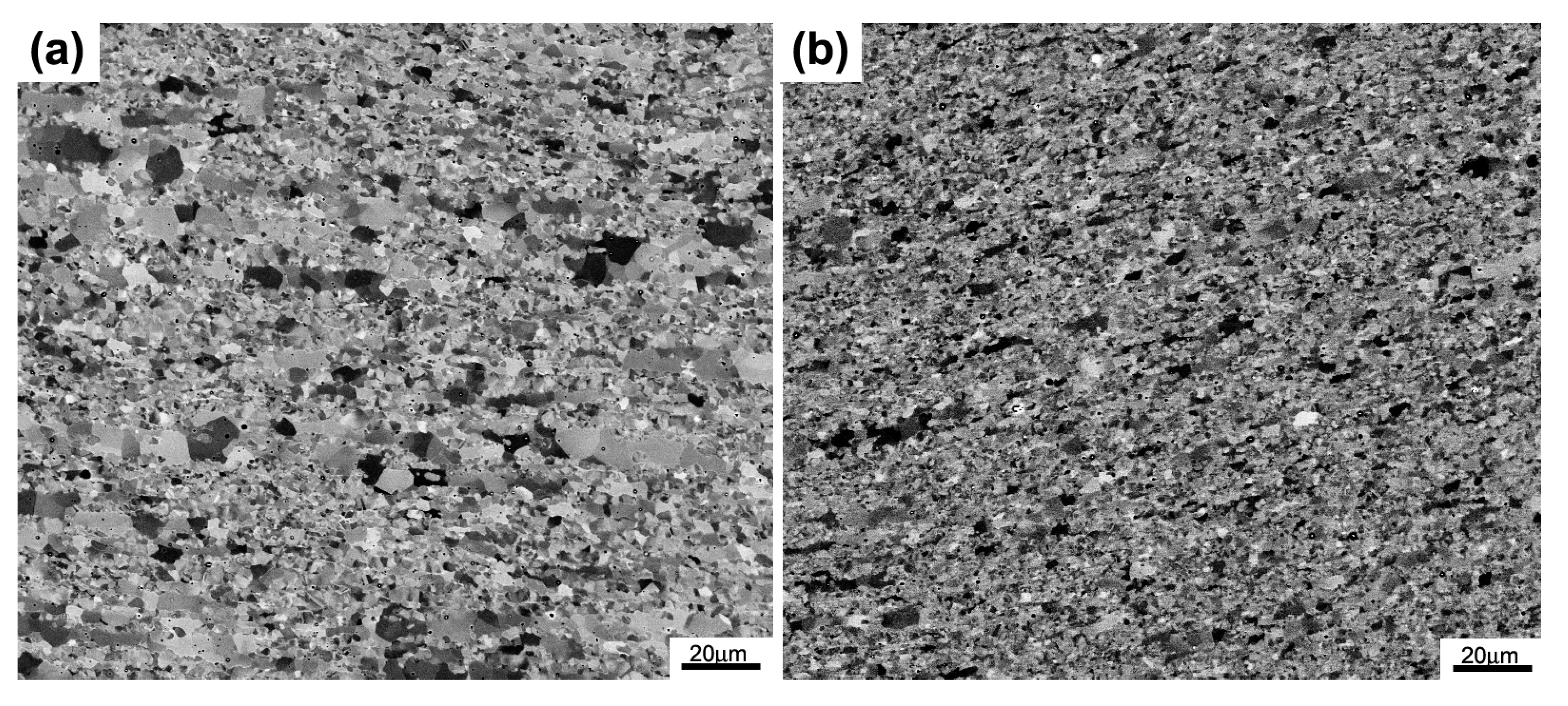
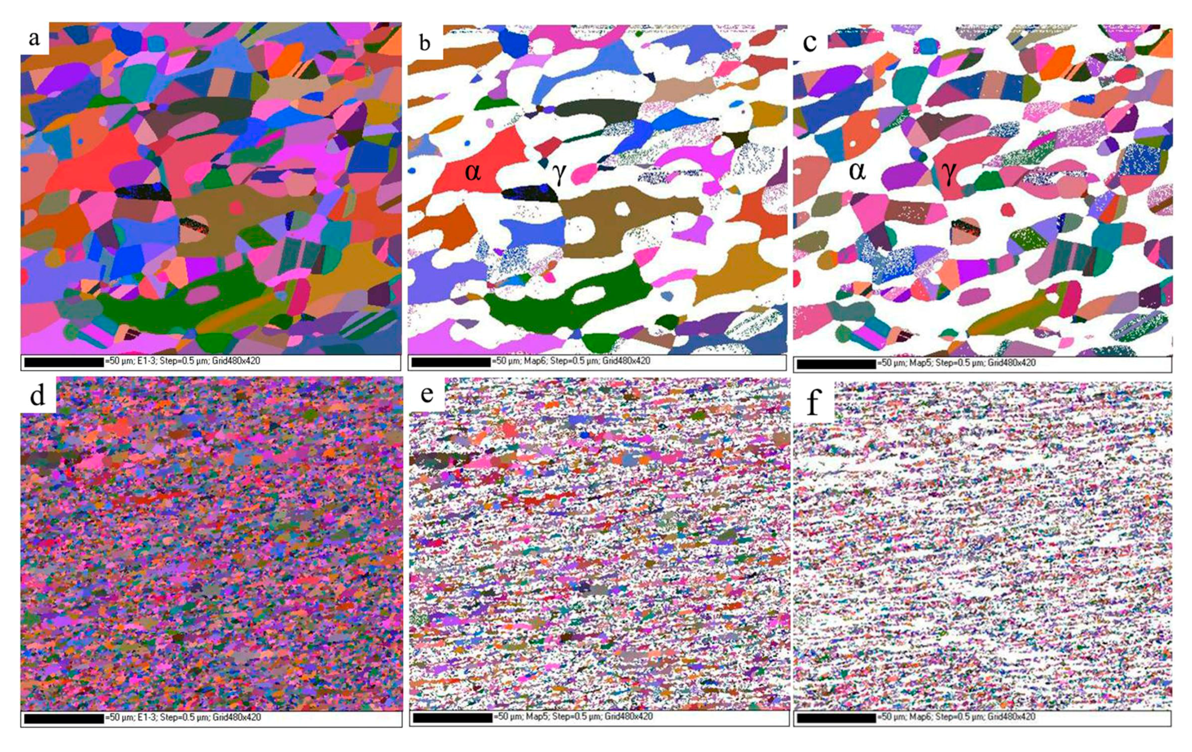
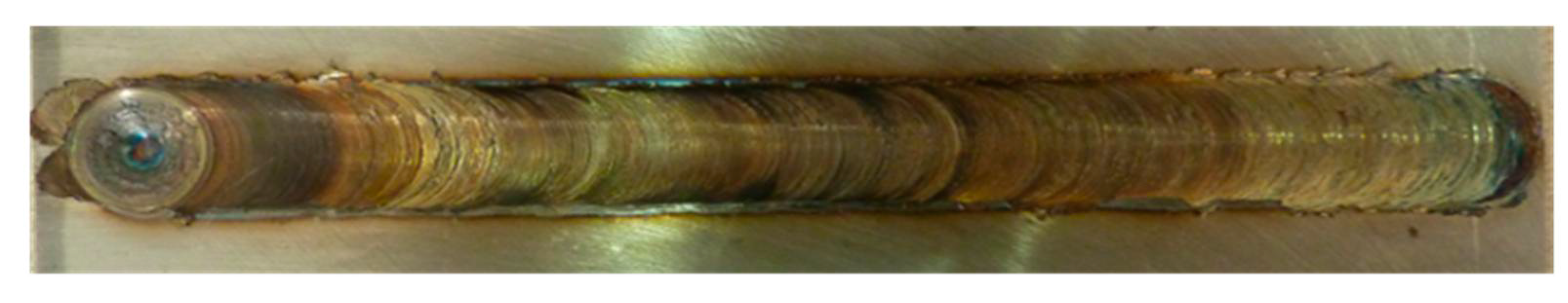
A high-quality FSW joint without deleterious phases is obtained by rapidly cooling the samples. The welded joint microstructure contains fine equiaxed grains in the SZ. The grains are exceptionally pronounced in the austenite phase.
(2)
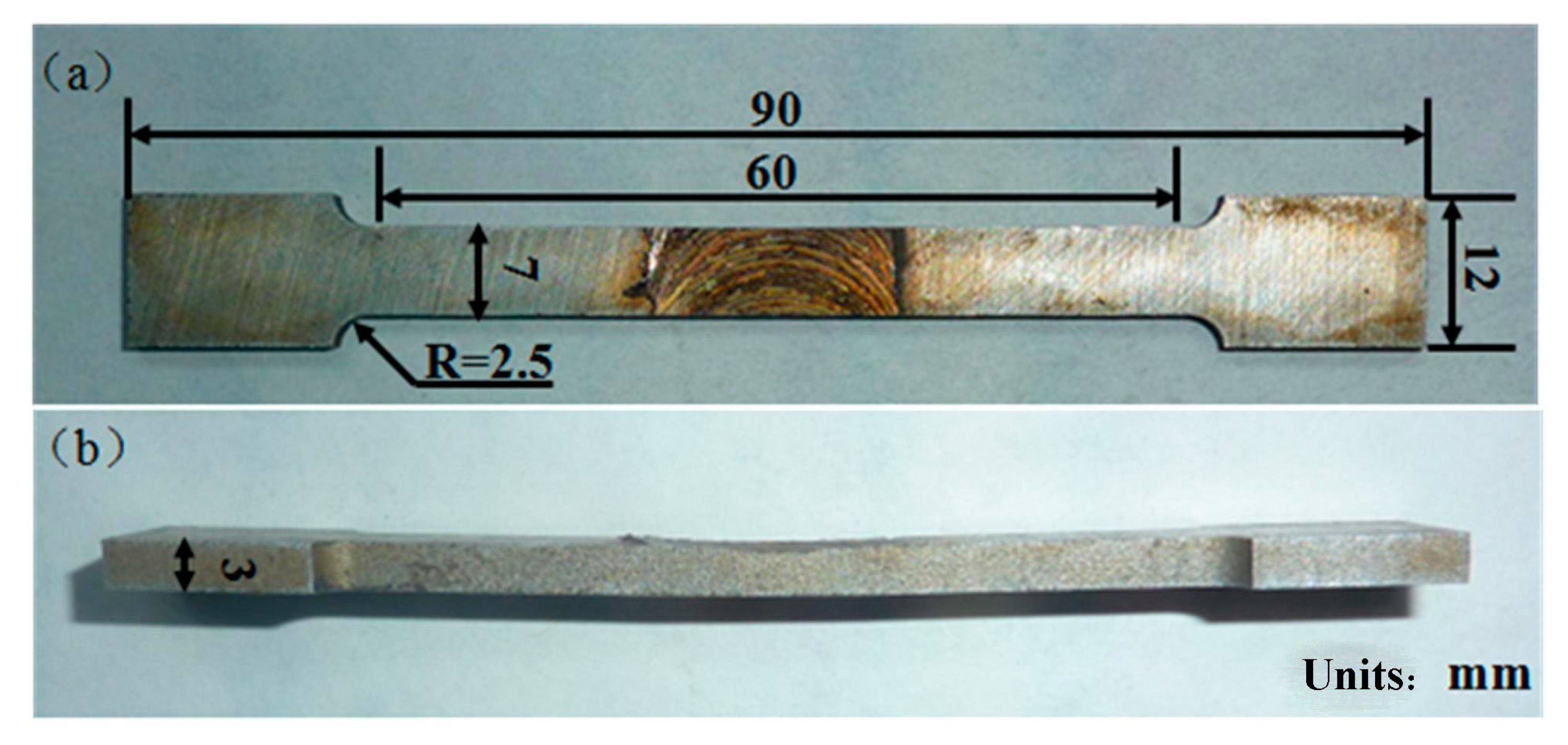
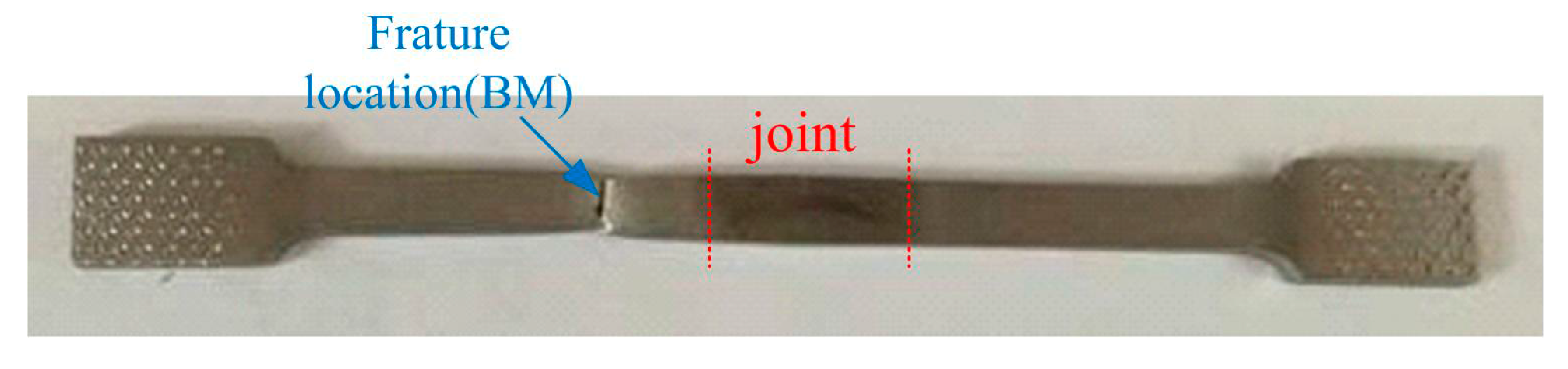
Failure of the tensile specimens is consistently located in the BM zone, suggesting that the welded joint overly matches the BM. Owing to their fine grains, the welded joints display a higher tensile strength than their BMs.
(3)
In the potentiodynamic polarization and impedance spectroscopy tests in NaCl solution, all SZs exhibit corrosion resistance superior to that of the BM.

Acknowledgments

This work was financially supported by The National Science Foundation of China (No. 51371123), The High-Tech Research Development Program (863 Program) of China (No. 2015AA034301), The Specialized Research Foundation of the Doctoral Program for Institution of Higher Education (Nos. 2013140211003, 20131402120004), The Natural Science Foundation of Shanxi Province (Nos. 2014011002-1, 201601D202034), Fund of the China Scholarship Council (CSC) and The Projects of International Cooperation in Shanxi (No. 201603D421026).

Author Contributions

This work was designed and mainly done by Jianchun Li, and he also took the job of the data analysis and write this paper. Corrosion resistance experiment was conducted by Xinglong Liu. Duplex stainless steel SAF2707 plate was provided by Guoping Li. Some constructive advices were obtained from Peide Han and Wei Liang.

Conflicts of Interest

The authors declare no conflict of interest.

References

  1. Hayes, F.H. Phase equilibria in duplex stainless steel. J. Less Common Met. 1985, 114, 89–96. [Google Scholar] [CrossRef]
  2. Weibull, I. Duplex stainless steels and their application, particularly in centrifugal separators: Part B Corrosion resistance. Mater. Des. 1987, 8, 82–88. [Google Scholar] [CrossRef]
  3. Kenneth, G.; Marie-Louise, N.; Martin, H.; Eduardo, G. Sandvik SAF 2707HD (UNS S32707)—A Hyper-Duplex Stainless Steel for Severe Chloride Containing Environments; Internal Lecture No. S-51-63; Sandvik Materials Technology: Sandviken, Sweden, 2006. [Google Scholar]
  4. Chail, G.; Kangas, P. Super and hyper duplex stainless steels: Structure, properties and application. Procedia Struct. Integr. 2016, 2, 1755–1762. [Google Scholar] [CrossRef]
  5. Ha, H.; Jang, M.; Lee, T.; Moon, J. Understanding the relation between phase fraction and pitting corrosion resistance of UNS S32759 stainless steel. Mater. Charact. 2015, 106, 338–345. [Google Scholar] [CrossRef]
  6. Ghosh, S.K.; Mondal, S. High temperature ageing behaviour of a duplex stainless steel. Mater. Charact. 2008, 59, 1776–1783. [Google Scholar] [CrossRef]
  7. Sathirachinda, N.; Pettersson, R.; Pan, J. Depletion effects at phase boundaries in 2205 duplex stainless steel characterized with SKPFM and TEM/EDS. Corros. Sci. 2009, 51, 1850–1860. [Google Scholar] [CrossRef]
  8. Deng, B.; Wang, Z.; Jiang, Y.; Sun, T.; Xu, J.; Li, J. Effect of cycles on the corrosion on the corrosion and mechanical properties of UNS S31803 duplex stainless steel. Corros. Sci. 2009, 51, 2969–2975. [Google Scholar] [CrossRef]
  9. Badji, R.; Bouabdallah, M.; Bacroix, B. Phase transformation and mechanical behavior in annealed 2205 duplex stainless seel welds. Mater. Charact. 2008, 59, 447–453. [Google Scholar] [CrossRef]
  10. Stenvall, P.; Holmquist, M. Weld Properties of Sandvik SAF 2707 HD; Sandvik materials technology: Sandviken, Sweden, 2008; Volume 11. [Google Scholar]
  11. Pramanik, A.; Littlefair, G.; Basak, A.K. Weldability of duplex stainless steel. Mater. Manuf. Process 2015, 30, 1053–1068. [Google Scholar] [CrossRef]
  12. Hsieh, R.I.; Liou, H.Y.; Pan, Y.T. Effects of cooling time and alloying elements on the microstructure of the Gleeble-simulated heat affected zone of 22% Cr duplex stainless steels. J. Mater. Sci. Perform. 2001, 10, 526–536. [Google Scholar] [CrossRef]
  13. Pardal, J.M.; Tavares, S.S.M.; Cindra Fonseca, M.; de Souza, J.A.; Côrte, R.R.A.; de Abreu, H.F.G. Influence of the grain size on deleterious phase precipitation in superduplex stainless steel UNS S32750. Mater. Charact. 2009, 60, 165–172. [Google Scholar] [CrossRef]
  14. Sieurin, H.; Sandstrom, R. Sigma phase precipitation in duplex stainless steel 2205. Mater. Sci. Eng. A 2007, 444, 271–276. [Google Scholar] [CrossRef]
  15. Kim, S.M.; Kim, J.; Tae, K.; Park, K.; Lee, C.S. Effect of Ce addition on secondary phase transformation and mechanical properties of 27Cr-7Ni hyper duplex stainless steels. Mater. Sci. Eng. A 2013, 573, 27–36. [Google Scholar] [CrossRef]
  16. Chen, Z.W.; Cui, S. On the forming mechanism of banded structures in aluminium alloy friction stir welds. Scr. Mater. 2008, 58, 417–420. [Google Scholar] [CrossRef]
  17. Hirata, T.; Oguri, T.; Hagino, H.; Tanaka, T. Influence of friction stir welding parameters on grain size and formablity in 5083 aluminum alloy. Mater. Sci. Eng. A 2007, 456, 344–349. [Google Scholar] [CrossRef]
  18. Sato, Y.S.; Nelson, T.W.; Sterling, C.J.; Steel, R.J.; Pettersson, C.O. Microstructure and mechanical properties of friction Stir Welded SAF 2507 super duplex stainless steel. Mater. Sci. Eng. A 2005, 397, 376–384. [Google Scholar] [CrossRef]
  19. Saeid, T.; Abdollah-Zadeh, A.; Shibayanagi, T.; Ikeuchi, K.; Assadi, H. On the formation of grain structure during friction stir welding of duplex stainless steel. Mater. Sci. Eng. A 2010, 527, 6484–6488. [Google Scholar] [CrossRef]
  20. Sarlak, H.; Atapour, M.; Esmailzadeh, M. Corrosion behavior of friction stir welded lean duplex stainless steel. Mater. Des. 2015, 66, 209–216. [Google Scholar] [CrossRef]
  21. Kim, S.; Jang, S.; Lee, I.; Park, Y. Effects of solution heat-treatment and nitrogen in shielding gas on the resistance to pitting corrosion of hyper hyper duplex stainless steel welds. Corros. Sci. 2011, 53, 1939–1947. [Google Scholar] [CrossRef]
  22. Jang, S.; Kim, S.; Lee, I.; Park, Y. Effect of shielding gas composition on phase transformation and mechanism of pitting corrosion of hyper duplex stainless steel welds. Mater. Trans. 2011, 52, 1228–1236. [Google Scholar] [CrossRef]
  23. Thomas, W.M.; Johnson, K.I.; Wiesner, C.S. Friction stir welding–recent developments in tool and process technologies. Adv. Eng. Mater. 2003, 5, 485–490. [Google Scholar] [CrossRef]
  24. Saeid, T.; Abdollah-Zadeh, A.; Assadi, H.; MalekGhaini, F. Effect of friction stir welding speed on the microstructure and mechanical properties of a duplex stainless steel. Mater. Sci. Eng. A 2008, 496, 262–268. [Google Scholar] [CrossRef]
  25. Wang, D.; Ni, D.R.; Xiao, B.L.; Ma, Z.Y.; Wang, W.; Yang, K. Microstructure evolution and mechanical properties of friction stir joint of Fe-Cr-Mn-Mo-N austenite stainless steel. Mater. Des. 2014, 64, 355–359. [Google Scholar] [CrossRef]
  26. Liu, F.C.; Nelson, T.W. In-situ material flow pattern around probe during friction stir welding of austenite stainless steel. Mater. Des. 2016, 110, 354–364. [Google Scholar] [CrossRef]
  27. Guerra, M.; Schmidt, C.; McClure, J.C.; Murr, L.E.; Nunes, A.C. Flow patterns during friction welding. Mater. Charact. 2003, 49, 95–101. [Google Scholar] [CrossRef]
  28. Fang, Y.L.; Liu, Z.Y.; Song, H.M.; Jiang, L.Z. Hot deformation behavior of a new austenite-ferrite duplex stainless containing high content of nitrogen. Mater. Sci. Eng. A 2009, 526, 128–133. [Google Scholar] [CrossRef]
  29. Magnani, M.; Terada, M.; Lino, A.O.; Tallo, V.P.; Fonseca, E.B.; Santos, T.F.; Ramirez, A.J. Microstructural and electrochemical characterization of friction stir welded duplex stainless steels. Int. J. Electrochem. Sci. 2014, 9, 2966–2977. [Google Scholar]
  30. Santos, T.F.; López, E.A.; Fonseca, E.B.; Ramirez, A.J. Friction stir welding of duplex and superduplex stainless steel and some aspects of microstructural characterization and mechanical performance. Mater. Res. 2016, 19, 117–131. [Google Scholar] [CrossRef]
  31. Esmailzadeh, M.; Shamanian, M.; Kermanpur, A.; Saeid, T. Microstructure and mechanical properties of friction Stir Welded lean duplex stainless steel. Mater. Sci. Eng. A 2013, 561, 486–491. [Google Scholar] [CrossRef]
  32. Sato, Y.S.; Harayama, N.; Kokawa, H.; Inoue, H.; Tadokoro, Y.; Tsuge, S. Evaluation of microstructure and properties in friction stir welded superaustenitic stainless steel. Sci. Technol. Weld. Join. 2009, 14, 202–209. [Google Scholar] [CrossRef]
  33. Ramkumar, K.D.; Thiruvengatam, G.; Sudharsan, S.P.; Mishra, D.; Arivazhagan, N.; Sridhar, R. Characterization of weld strength and impact toughness in the multi-pass welding of super-duplex stainless steel UNS2750. Mater. Des. 2014, 60, 125–135. [Google Scholar] [CrossRef]
  34. Hajian, M.; Abdollah, A.; Rezaei-Nejad, S.S.; Assaddi, H.; Hadavi, S.M.M.; Chung, K.; Shokouhimehr, M. Microstructure and mechanical properties of friction stir processed AISI 316L stainless steel. Mater. Des. 2015, 67, 82–94. [Google Scholar] [CrossRef]
  35. Li, H.B.; Jiang, Z.H.; Feng, H.; Zhang, S.C.; Li, L.; Han, P.D. Microstructure, mechanical, and corrosion properties of friction Stir Welded high nitrogen nickel-free austenitic stainless steel. Mater. Des. 2015, 84, 291–299. [Google Scholar] [CrossRef]
  36. Rlston, K.D.; Birbilis, N.; Davies, C.H.J. Revealing the relationship between grain size and corrosion rate of metals. Scr. Mater. 2010, 63, 1201–1204. [Google Scholar] [CrossRef]
  37. Jinlong, L.; Tongxiang, L.; Chen, W.; Limin, D. Comparision of corrosion properties of passive films formed on coarse grained and ultrafined grained AISI 2205 duplex stainless steels. J. Electroanal. 2015, 757, 263–269. [Google Scholar] [CrossRef]
  38. Luo, H.; Dong, C.F.; Xiao, K.; Li, X.G. Characterization of passive film on 2205 duplex stainless steel in sodium thiosulphate solution. Appl. Surf. Sci. 2011, 258, 631–639. [Google Scholar] [CrossRef]
  39. Eghlimi, A.; Shamanian, M.; Raeissi, K. Effect of current type on microstructure and corrosion resistance of super duplex stainless steel claddings produced by the tungsten arc welding process. Surf. Coat. Technol. 2014, 244, 45–51. [Google Scholar] [CrossRef]
  40. Jinlong, L.; Tongxiang, L.; Limin, D.; Chen, W. Influence of sensitization on microstructure and passive property of AISI 2205duplex stainless steel. Corros. Sci. 2016, 104, 144–151. [Google Scholar] [CrossRef]
  41. Donik, Č.; Kocijan, A.; Grant, J.T.; Jenko, M.; Drenik, A.; Pihlar, B. XPS study of duplex stainless steel oxidized by oxygen atoms. Corros. Sci. 2009, 51, 827–832. [Google Scholar] [CrossRef]
Figure 1. Schematic illustration of the welding tool used in the experiment [23].
Metals 07 00138 g001
Figure 2. Surface morphology of friction stir welding (FSW) butt joint.
Metals 07 00138 g002
Figure 3. (a) The front; (b) sectional views of the transverse tensile specimen.
Metals 07 00138 g003
Figure 4. Optical microscopy of cross section of the joint (a); related microstructure (b) base metal (BM); (c) stir zone (SZ); (d) stir zone—advancing side (SZ-AS); (e) thermo-mechanically affected zone—advancing side (TMAZ-AS); (f) thermo-mechanically affected zone—retreating side (TMAZ-RS).
Metals 07 00138 g004
Figure 5. Backscatter electron (BSE) images of the SZ after electrolytic polishing (a) near the top surface; (b) at the bottom.
Metals 07 00138 g005
Figure 6. EBSD maps of the BM and the SZ: (a) map for the BM; (b) ferrite of the BM; (c) austenite of the BM; (d) map for the SZ; (e) ferrite of the SZ; (f) austenite of the SZ.
Metals 07 00138 g006
Figure 7. XRD pattern of base metal and SZ.
Metals 07 00138 g007
Figure 8. Hardness profile across the joint.
Metals 07 00138 g008
Figure 9. Hardness profile along the weld thickness.
Metals 07 00138 g009
Figure 10. (a) Stress–strain curves of the BM and FSW joint; and (b) results of tensile test.
Metals 07 00138 g010
Figure 11. The macro pictures of the failure in the BM.
Metals 07 00138 g011
Figure 12. (a) Optical micrograph of the tensile surface; (b) SEM morphology of the weldment fracture surfaces; (c) EDX of the austenite phase; (d) EDX of the ferrite phase.
Metals 07 00138 g012
Figure 13. Potentiodynamic polarization curves of the BM andthe SZ in a 3.5 wt. %NaCl solution.
Metals 07 00138 g013
Figure 14. Nyquist (a); and Bode (b) plots for the BM and the SZ in a 3.5 wt. % NaCl solution.
Metals 07 00138 g014
Figure 15. Equivalent circuit used for simulating bilayer oxide film on the BM andthe SZ.
Metals 07 00138 g015
Table 1. Chemical composition of base material (wt. %).
ElementsCNSiMnCrNiCoMoCuCeFe
Content (wt. %)0.020.470.421.0027.076.710.994.660.850.03Bal.
Table 2. The EIS fitting results of the BM and SZ.
AreaRs (Ω∙cm2)Q1 (uF∙cm−2)R1 (kΩ∙cm2)n1R2 (kΩ∙cm2)Q2 (uF∙cm−2)n2
BM30.5319.100.510.98262.5016.500.77
SZ27.6129.2547.350.94304.5012.940.84

