On the Invariance of Hardness at Vickers Indentation of Pre-Stressed Materials


Department of Solid Mechanics, Royal Institute of Technology, SE-10044 Stockholm, Sweden; [email protected]; Tel.: +46-8-790-7540
Metals 2017, 7(7), 260; https://doi.org/10.3390/met7070260
Submission received: 18 June 2017
/
Revised: 30 June 2017
/
Accepted: 6 July 2017
/
Published: 7 July 2017
(This article belongs to the Special Issue Experimental Assessment of Residual Stress in Engineering Materials Components)
Abstract
:The influence from residual surface stresses on global indentation properties, i.e., hardness and size of the contact area, have been studied quite frequently in recent years. A fundamental assumption when evaluating such tests is that the material hardness is independent of any residual stresses. This assumption has been verified in the case of cone indentation of classical Mises elastoplastic materials. However, a detailed investigation of this feature in the case of three-dimensional indentation, i.e., Vickers and Berkovic indentation, has not been presented previously. It is therefore the aim of the present study to remedy this shortcoming using finite element methods. The numerical results pertinent to Vickers indentation clearly show that the material hardness is independent of residual (or applied) stresses (also in case of three-dimensional indentation problems). The limitations of the validity of hardness invariance are also discussed in some detail.
1. Introduction
Residual stresses can be a very dangerous feature when it comes to the reduction of load-carrying capacity and strength in general. Such stresses can be introduced through mechanical and/or thermal loading, but also during engineering, processing, and production of monolithic and composite materials. Naturally, the best way to avoid any destructive influence from residual stresses is to substantially reduce the levels of the residual fields. However, very often this is not an easy task to undertake, and then a more realistic approach to the problem is to quantify these stresses and account for them during design and dimensioning. There are many methods proposed for this purpose (hole-drilling, layer removal, beam bending, neutron and X ray tilt techniques, just to mention a few) but lately indentation testing has emerged as a strightforward and, indeed, non-destructive alternative. Accordingly, residual stress determination using indentation has developed into a very active research field during the last decades.
Now twenty years ago, Tsui et al. [1] and Bolshakov et al. [2] investigated experimentally and numerically the influence of applied stress on indentation quantities on the indentation of aluminum alloy 8009. Very interesting results were presented and it was shown that the indentation hardness was not significantly affected by applied (residual) stresses, while the amount of piling-up of material at the contact contour proved to be sensitive to stress. In short, piling-up increased when the applied stresses were compressive and decreased at tensile stresses. Following these investigations, more theoretically inclined studies emerged that sought to gain a quantitative understanding of the mechanics of the problem cf. [3,4,5,6,7,8,9] (just to mention a few). In most of these studies progress was made based on the fact that, as hardness was not affected by residual stresses, the deformation at the contact contour could be directly correlated to the magnitude of the residual (or applied stresses).
Even though the invariance of indentation hardness obviously is a fundamental part of an analysis of residual stress effects at indentation, the accuracy of this feature has not been investigated in great detail from a theoretical/numerical point of view. Scattered results have been presented in for example [2,4] and also in more detail in [10]. In the latter case general residual (applied) surface stresses were considered. All of these efforts were, however, restricted to conical, axisymmetric, and indentation (and to the authors knowledge there has been no attempt to investigate this issue for the three-dimensional case (Vickers and Berkovic indenters)). Instead it is often quietly assumed that the cone indentation results are at least qualitatively valid, also in a three-dimensional case.
It is certainly not obvious, though, that it is sufficient for the three-dimensional case to numerically prove the invariance of hardness at cone indentation. The mechanical fields at Vickers and Berkovic indentation are much more involved than in the axisymmetric conical case due to the presence of additional sharp corners. Accordingly, it is possible that the superposition of a residual stress field could lead to different mechanical behavior at the two types of indentations.
Accordingly, it is the aim of the present study to investigate this feature in detail. In doing so, the finite element method will be relied upon, and then the commercial package ABAQUS [11], in particular, will be used. The analysis is for clarity, but not for necessity; it is restricted to Vickers indentation, see Figure 1, of elastic-ideally plastic materials relying upon classical Mises plasticity with homogeneous residual equi-biaxial stress fields. It should be emphasized that since only Mises plasticity is considered, strain gradient plasticity (indentation size) effects are not considered, which limits the validity of the present analysis to indentation depths above approximately 1 μm.
In addition to the above analysis, a qualitative discussion related to the effects of elastic deformations is also included at the end of the article. No further numerical results are presented but as shown in example [10], elasticity can induce residual stress dependence of hardness when it comes to cone indentation, and this issue is presently scrutinized pertinent to three-dimensional Vickers indentation.
2. Materials and Methods
The theoretical foundation laid down in [4,9] will be relied upon for background. This foundation rests on the invariance of hardness, which will be tested presently using the finite element method. Especially, as already mentioned above, the commercial package ABAQUS [11] is used.
The analyses concerns Vickers indentation, see Figure 1, of elastic-ideally plastic materials. Plasticity is modelled using the standard Prandtl-Reuss (Mises) equations. Only homogeneous residual equi-biaxial stress fields are considered. The restrictions of the problem are introduced for clarity but not for necessity. The results will be correlated based on the well-known non-dimensional strain parameter Λ suggested by Johnson [12,13] according to
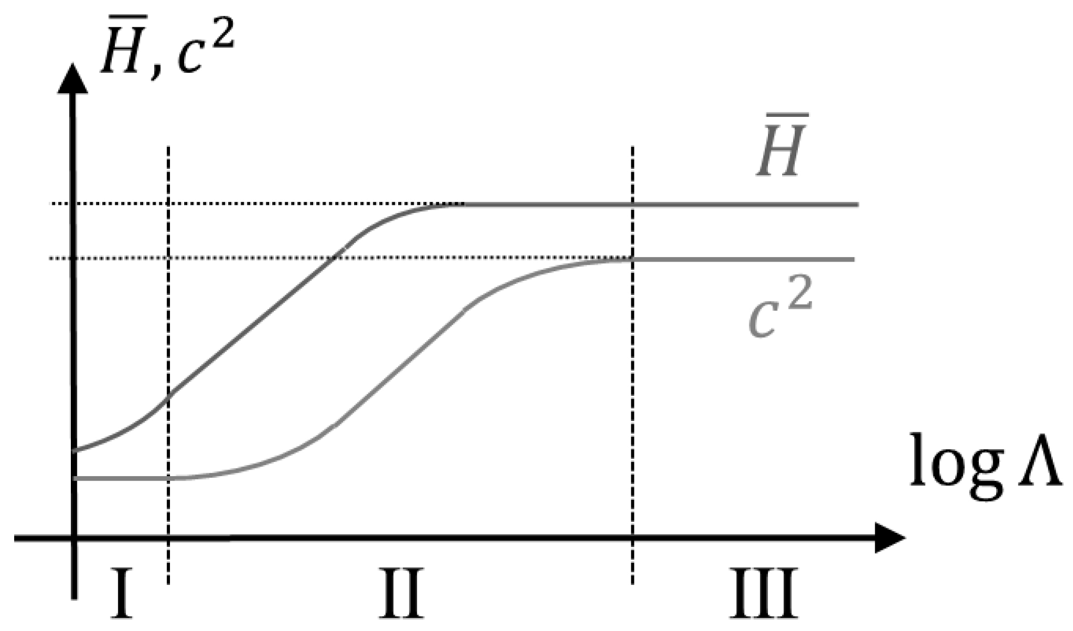
where E, ν, and σy are Young’s modulus, Poisson’s ratio, and the initial material flow stress, respectively. It should be noted that in Equation (1), only elastic-ideal plasticity is considered, but this limitation can be taken care of by replacing σy with the flow stress at a representative value of the effective plastic strain. Furthermore, in Equation (1), β is the angle between the sharp indenter and the undeformed surface of the material, as indicated in Figure 1 β = 22° for a Vickers indenter geometry. By using the Λ-parameter, Johnson [12,13] also characterized three levels, see Figure 2, of indentation (contact) behavior pertinent to the behavior of the material hardness H, here and in the sequel defined as the average contact pressure. These levels are: level I, representing almost purely elastic indentation; level II, representing a contact behavior where both elastic and plastic material properties are of importance; and level III, corresponding to a case where plasticity dominates the indentation problem (this level is at a sharp indentation pertinent to most engineering metals and alloys).
Λ = Etanβ/(σy(1 − ν2))
Based on extensive investigations, cf. e.g., [4,9], it is properly confirmed in the case of cone indentation that the material hardness is invariant of residual stresses at level III contact. Other global indentation properties do, however, show dependence of such stresses and of particular interest then is the relative contact area.
c2 = A/Anom.
In Equation (2), the areas A (true contact area) and Anom (nominal contact area) are pertinent to projected contact areas. Note that c2 = 1, when neither sinking-in nor piling-up occurs at the contact boundary.
Even though the parameter c2 is not of immediate interest presently it is, indeed, of substantial importance for the theoretical background to understand the dependence of this parameter of residual stress. This dependence was analysed in [4] and the formula
was derived for the case of equi-biaxial residual stresses σres and residual effective plastic strains εres. Other parameters in Equation (3) are; c2(εres, σres = 0) is the c2-value for a strained material with no residual stress and σy(εres) is the yield stress of the material exhibiting a residual effective plastic strain εres. At ideal plasticity Equation (3) becomes
due to the fact that the yield stress does not depend on the plastic strain state. It should be mentioned, as discussed in [14], that predictions made by Equations (3) and (4) are more accurate in tension than in compression.
c2 = c2(εres, σres = 0) − 0.32ln(1 + (σres/σy(εres )))
c2 = c2(σres = 0) − 0.32ln(1 + (σres/σy))
The theoretical foundation for Equations (3) and (4) is the equivalence of mechanical fields close to the indenter in case of either contact induced stresses in a virgin (unstressed) material or contact induced stresses in a material with an initial material yield stress σy + σres. This was shown in [4] from numerical (FEM) simulations. Accordingly, using an apparent yield stress
in Λ in Equation (1), according to
makes it possible to rely on the universal c2-curve in Figure 2 regardless of whether residual stresses are present or not. As a consequence, the universal c2-curve in Figure 2 can be used to determine σres in a situation where c2(σres = 0) is known. The accuracy of this approach to residual stress determination is, of course, based on the finding that elasticity influences c2 in a wider range of Λ-values than what is the case for hardness (see Figure 2).
σy,apparent = σy + σres
Λ = Etanβ/(σy,apparent(1 − ν2)),
However, the above discussed difference of mechanical behavior at tension and compression reduced the accuracy of the results when relying on Equation (4). For this reason, Rydin and Larsson [9] restudied the definition of σy,apparent and it was found that general high accuracy was achieved by replacing Equation (5) with the expression
where
Explicitly, it was suggested in [9] that the relation
should replace Equation (4) above. It was shown by Rydin and Larsson [9] that Equation (9) improved very much on the situation as compared with the results from Equation (4), and high accuracy predictions in both tension and compression were achieved in case of elastic-ideally plastic material behaviour.
σy,apparent = σy + Fσres,
F = 0.52, σres < 0
F = 1.77, σres > 0.
F = 1.77, σres > 0.
c2 = c2(σres = 0) − 0.35ln(1 + (Fσres/σy))
It should be strongly emphasized, once again, that the results above are strictly valid only for axisymmetric cone indentation. However, in case of hardness invariance the fundamentals of a corresponding analysis pertinent to a three-dimensional indenter geometry (Vickers and Berkovich indentation) are very similar. Accordingly, to clarify this matter, hardness invariance is of considerable importance and, in particular, to correlate these findings with the Johnson [12,13] parameter Λ.
Although not very frequently attempted, a number of finite element analyses of three-dimensional sharp indentation problems have been presented in the literature. In this context, Carlsson and Larsson [4] (resting on the numerical approach laid down by Giannakopoulos et al. [15] for stress-free indentation) were perhaps the first to also introduce pre-stresses in such an analysis; presenting results of high accuracy and the fundamentals of their approach will be adhered to here. The accuracy and reliability of the numerical procedure was investigated in detail in [4], and this issue will not be dwelt upon further.
Accordingly, the present analysis concerns Vickers indentation of classical elastic-ideally plastic materials with isotropic hardening. Plastic strain-hardening is not considered for clarity as this would dim the conclusions related to the effect from pre-stressing. Explicitly then, the Mises effective stress takes on the value
where σy is the material yield stress. Large deformations are accounted for to ensure accuracy and the hypoelastic behavior of the material is determined by the elastic modulus E and Poisson’s ratio ν.
σe = σy
As far as the boundary value problem is concerned it remains to stipulate that pre-stresses (residual stresses) are enforced by prescribed displacement at the outer boundary prior to indentation. As these pre-stresses are enforced before indentation their magnitude can be directly controlled by Hooke’s law. Only equi-biaxial residual stress fields are considered in the analysis. Furthermore, the outer boundary is placed sufficiently far away from the contact region in order to avoid mechanical interference.
Even though some simplifications are described above, the resulting boundary value problem is very complicated and finite element methods have to be relied upon in order to determine the behavior of global indentation variables. The pre-stressing of the material further complicates the situation. Based on the guidelines discussed above the commercial package ABAQUS [11] will be used for this purpose. The finite element mesh is shown in Figure 3, including 14055 eight-noded elements and 16,527 nodes. Due to the obvious symmetries only 1/8 of the problem is discretized.
Concerning the contact problem it is assumed that the Vickers indenter is rigid and that frictional effects can be neglected. It has been shown by, for example, Giannakopoulos and Larsson [16] that such an assumption is very accurate when it comes to determining global indentation properties such as hardness and relative contact area.
As for the introduction of the residual stress and strain fields into the numerical calculations, this was done, as indicated in Figure 4, by introducing prescribed radial displacements at the outer boundary of the finite element mesh prior to indentation. Accordingly, in the present context, residual stresses are treated as equi-biaxial pre-stresses and no distinction between applied and residual stresses is made in the analysis. In all finite element simulations, the indenter was impressed to a prescribed indentation depth, while the prescribed radial displacements at the outer boundary were kept constant during indentation.
In the analysis the material hardness H is, as mentioned above, defined as the average contact pressure at indentation. Accordingly,
where P is the maximum indentation load and A is the corresponding value of the projected contact area. It should be noted that due to the self-similarity of the problem, and the fact that no characteristic length is present in the governing equations, the material hardness H is constant during a sharp indentation test on classical elastic-plastic materials.
H = P/A
3. Results and Discussion
In the presentation below, the behavior of the material hardness at Vickers indentation of elastic-ideally Mises plastic materials will be investigated in the presence of in-plane (X1-X3-plane) equi-biaxial residual (or applied) stresses. Obviously, strain gradient plasticity (indentation size) effects are not considered, and this limits the validity of the analysis to indentation depths above 1 μm. The investigation is based on the finite element method and the material properties are chosen to be
E = 200 GPa, ν = 0.3, σy = 200 MPa, 400 MPa.
The values in (12) are pertinent to many metallic materials, in particular steel. These values are also chosen in order to ensure that rigid plastic level III contact conditions are achieved. This is the contact condition being of most interest in a practical situation (as being pertinent to most engineering metals, such as steel and aluminium) and is, as mentioned above, characterized by the fact that plastic deformation is dominating the indentation contact process.
Johnson [12,13] stated that when Λ > 30 rigid-plastic contact is ensured (see also Figure 2), at least when the behaviour of the hardness is at issue. With the present values on the material constants in (12) the values
are determined from Equation (1), which obviously ensures rigid plastic contact conditions.
Λ = 444, 222
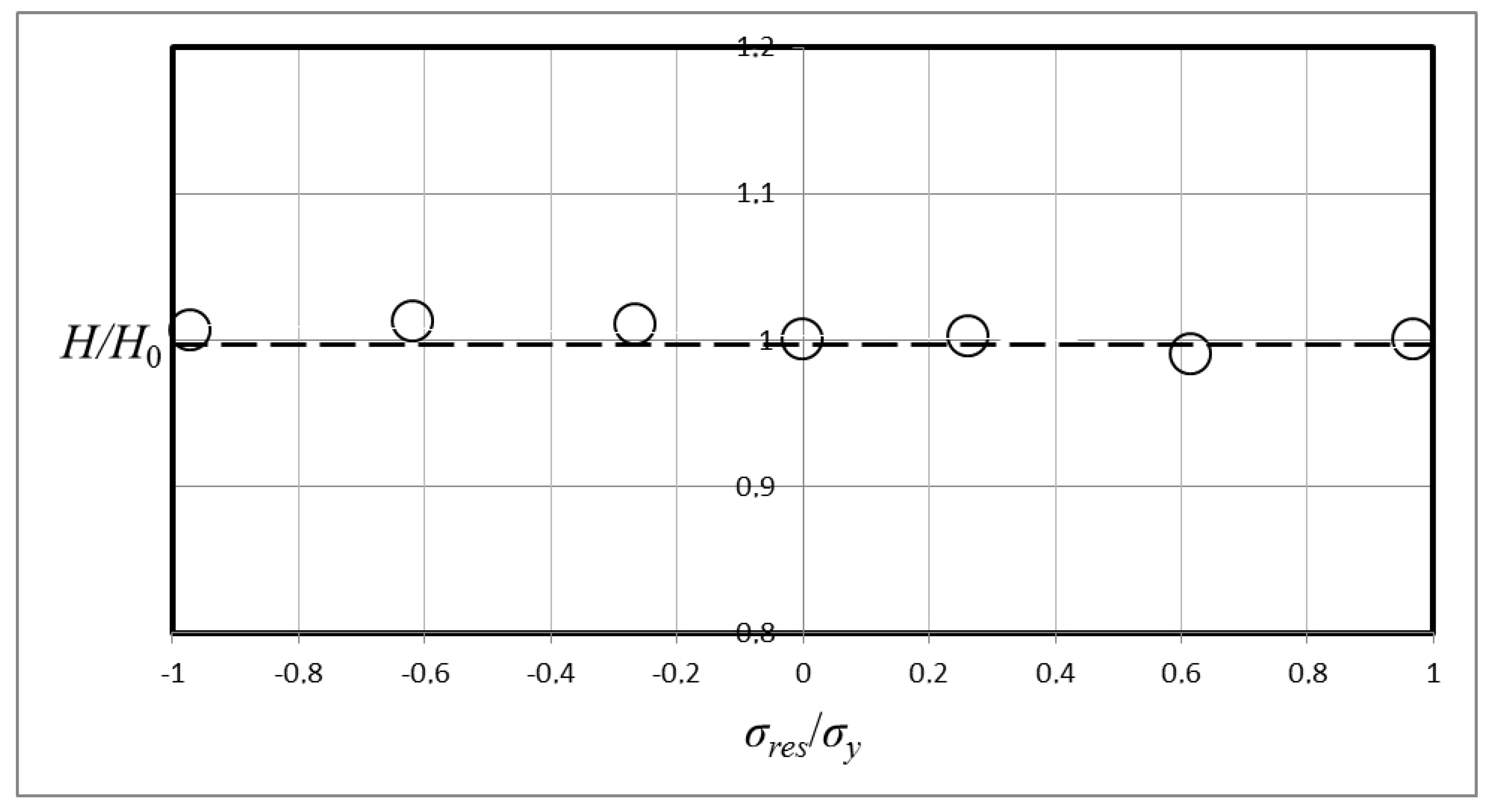
Now turning our attention to the results from the numerical analysis, these are shown in Figure 5 and Figure 6. The results in the two figures are pertinent to the two values on the material yield stress σy stated in (12). Explicitly, the results in Figure 5 are for σy = 200 MPa and in Figure 6 for σy = 400 MPa.
In the presentation, the nondimensionalized hardness H/H0 is depicted as a function of the nondimensionalized equi-biaxial residual stress field σres/σy. The parameter H0 is the material hardness with no pre-stresses and was presently determined from the finite element calculations as
for the two different values on the yield stress σy. It should be noted, in passing, that the hardness values in (14) are in good agreement with the well-known Tabor-formula [17] yielding
at Vickers indentation (the corresponding result at cone indentation is
as determined by Atkins and Tabor [18]). This result certainly gives even more confidence that rigid-plastic conditions are achieved and also confidence in general concerning the accuracy of the finite element approach.
H0 = 555 MPa, 1090 MPa
H = 2.8 σy
H = 2.54 σy
In short then, concerning the results in Figure 5 and Figure 6, it is very obvious that the material hardness is independent of residual (applied) stresses at Vickers indentation. Indeed, the effect from these stresses is so small that it can be stated that any variations are within the numerical accuracy. This conclusion is clearly valid even for applied stresses close to the material yield stress, and for both the tensile and the compressive case.
The fact that the invariance holds for both the tensile and the compressive case is interesting and certainly not obvious. It has been shown previously (cf. [14]) that many important indentation variables are very dependent on the sign of the pre-stresses and, accordingly, the present results are encouraging from an indentation (residual stress) modelling point of view.
Indeed, the present results are generally very encouraging when it comes to the modeling of the effect from residual stresses at indentation. With the invariance of hardness so established in the rigid plastic contact regime (and also in the practically important case of three-dimensional indenters) it is possible to concentrate in full in order to determine the influence from these stresses on other indentation variables such as the relative contact area.
Having said this, though, it is, of course, also important to discuss the validity of hardness invariance at indentation. The physical background for the hardness invariance rests upon the fact that rigid plastic contact behavior is at issue even when the residual (applied) stresses are present. This is most often the case but might fail at extreme values on the applied tensile stresses (and at material properties pertinent to, for example, ceramics and polymers) and the consequence of such a situation is discussed below. Previous relevant results for cone indentation [9] are relied upon for this qualitative discussion.
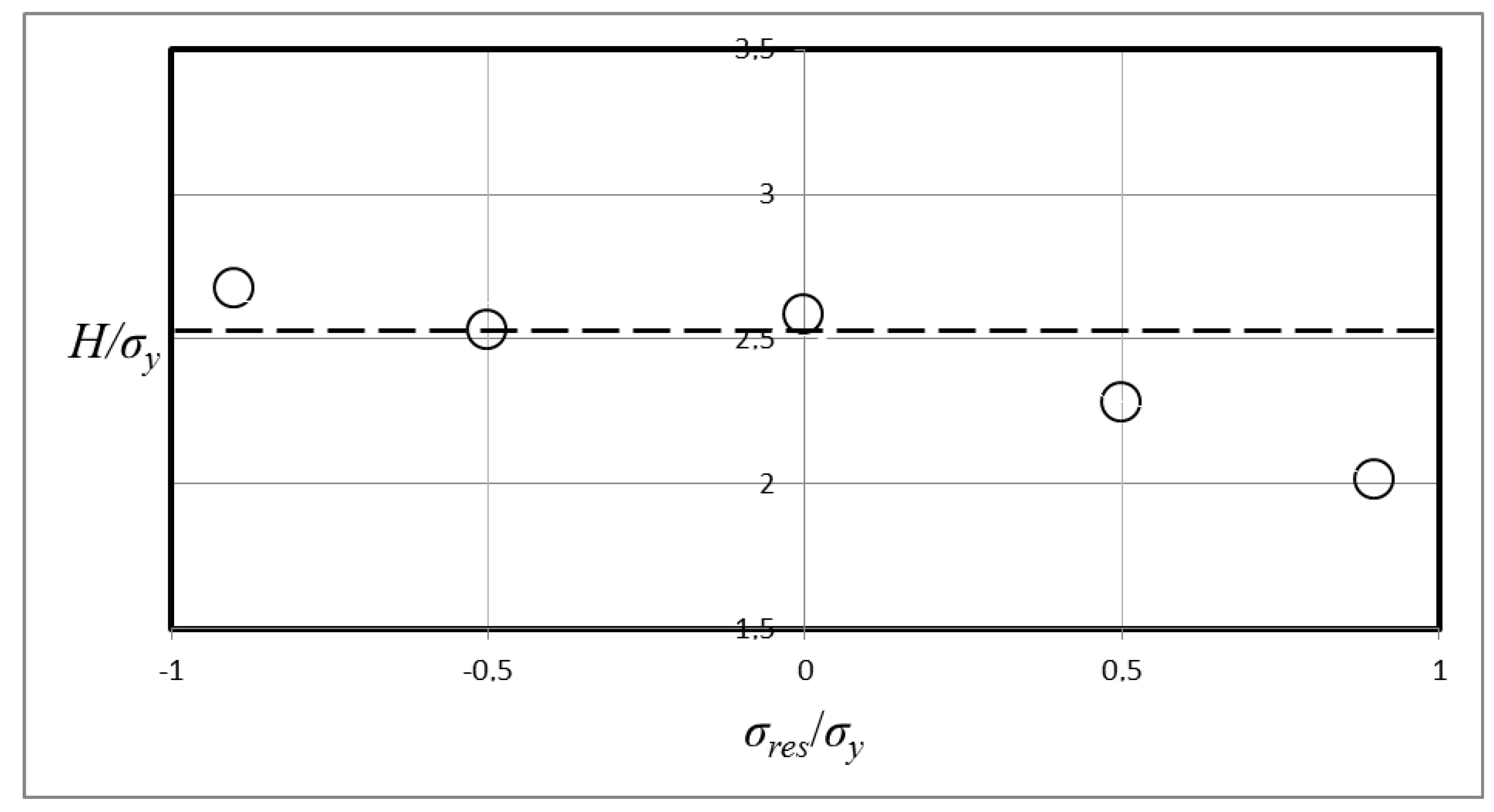
Pertinent results from [9] are shown in Figure 7 and Figure 8, where cone hardness values are shown for two elastic-ideally plastic materials, defined by ln Λ = 3, 5, at different values on σres/σy. It can be noticed in this case that invariance is no longer valid at approximately ln Λ = 3, where Λ is defined according to Equation (1), and σres/σy > 0. If Λ is defined according to Equation (6) this would suggest that for ln Λ smaller than approximately 3 hardness invariance is no longer valid. This value corresponds very well with the statement by Johnson [12,13] that Λ = 30 constitute the border between level II and level III contact behavior at indentation of virgin (not pre-stressed) materials.
The outcome of the above discussion leads to two important conclusions. First of all, the invariance of hardness is valid when Λ, defined according to Equation (6), takes on values pertinent to level III indentation and secondly, that Λ defined according to Equation (6) is an appropriate tool for correlation of residual stresses with global indentation parameters. Even though these latter results are based on analyses of cone indentation there is no reason to assume, remembering the often reported agreement between axisymmetric and three-dimensional indentation results, that they are invalid in case of Vickers indentation. Indeed, the agreement between the axisymmetric and three-dimensional indentation result is obviously also manifested in the present analysis.
Finally, it is worth mentioning that the present approach could very well be applied to other types of contact problems. One of these problems could be scratching and scratch testing where correlation of material and contact properties, in the spirit of Johnson [12,13], have been discussed for some time now (cf. [19,20,21,22]). It remains, however, to undertake an analysis that also incorporates residual stresses in this special type of global quantity correlation.
4. Concluding Remarks
A numerical investigation has been performed in order to study the invariance of the material hardness at Vickers indentation of pre-stressed elastic-plastic materials. The invariance is proven within very good accuracy which is encouraging for a situation where modelling of the effect from residual stresses at indentation is at issue. The limitations of the validity of hardness invariance are also discussed in some detail and shown to be in direct correspondence with the validity of a contact behavior dominated by rigid plastic deformations.
Conflicts of Interest
The author declares no conflict of interest.
References
- Tsui, T.Y.; Oliver, W.C.; Pharr, G.M. Influences of stress on the measurement of mechanical properties using nanoindentation. Part I. Experimental studies in an aluminum alloy. J. Mater. Res. 1996, 11, 752–759. [Google Scholar] [CrossRef]
- Bolshakov, A.; Oliver, W.C.; Pharr, G.M. Influences of stress on the measurement of mechanical properties using nanoindentation. Part II. Finite element simulations. J. Mater. Res. 1996, 11, 760–768. [Google Scholar] [CrossRef]
- Suresh, S.; Giannakopoulos, A.E. A new method for estimating residual stresses by instrumented sharp indentation. Acta Mater. 1998, 46, 5755–5767. [Google Scholar] [CrossRef]
- Carlsson, S.; Larsson, P.L. On the determination of residual stress and strain fields by sharp indentation testing. Part I. Theoretical and numerical analysis. Acta Mater. 2001, 49, 2179–2191. [Google Scholar] [CrossRef]
- Swadener, J.G.; Taljat, B.; Pharr, G.M. Measurement of residual stress by load and depth sensing indentation with spherical indenters. J. Mater. Res. 2001, 16, 2091–2102. [Google Scholar] [CrossRef]
- Lee, Y.H.; Kwon, D. Estimation of biaxial surface stress by instrumented indentation with sharp indenters. Acta Mater. 2004, 52, 1555–1563. [Google Scholar] [CrossRef]
- Bocciarelli, M.; Maier, G. Indentation and imprint mapping method for identification of residual stresses. Comput. Mater. Sci. 2007, 39, 381–392. [Google Scholar] [CrossRef]
- Huber, N.; Heerens, J. On the effect of a general residual stress state on indentation and hardness testing. Acta Mater. 2008, 56, 6205–6213. [Google Scholar] [CrossRef]
- Rydin, A.; Larsson, P.L. On the correlation between residual stresses and global indentation quantities: Equi-biaxial stress field. Tribol. Lett. 2012, 47, 31–42. [Google Scholar] [CrossRef]
- Larsson, P.L.; Blanchard, P. On the invariance of hardness at sharp indentation of materials with general biaxial residual stress fields. Mater. Des. 2013, 52, 602–608. [Google Scholar] [CrossRef]
- ABAQUS. User’s Manual Version 6.9; Hibbitt, Karlsson and Sorensen Inc.: Pawtucket, RI, USA, 2009. [Google Scholar]
- Johnson, K.L. The correlation of indentation experiments. J. Mech. Phys. Solids 1970, 18, 115–126. [Google Scholar] [CrossRef]
- Johnson, K.L. Contact Mechanics; Cambridge University Press: Cambridge, UK, 1985. [Google Scholar]
- Larsson, P.L. On the mechanical behavior at sharp indentation of materials with compressive residual stresses. Mater. Des. 2011, 32, 1427–1434. [Google Scholar] [CrossRef]
- Giannakopoulos, A.E.; Larsson, P.L.; Vestergaard, R. Analysis of Vickers indentation. Int. J. Solids Struct. 1994, 31, 2679–2708. [Google Scholar] [CrossRef]
- Giannakopoulos, A.E.; Larsson, P.L. Analysis of pyramid indentation of pressure sensitive hard metals and ceramics. Mech. Mater. 1997, 25, 1–35. [Google Scholar] [CrossRef]
- Tabor, D. Hardness of Metals; Cambridge University Press: Cambridge, UK, 1951. [Google Scholar]
- Atkins, A.G.; Tabor, D. Plastic indentation in metals with cones. J. Mech. Phys. Solids 1965, 13, 149–164. [Google Scholar] [CrossRef]
- Bucaille, J.L.; Felder, E.; Hochstetter, G. Experimental and three-dimensional finite element study of scratch test of polymers at large deformations. J. Tribol. 2004, 126, 372–379. [Google Scholar] [CrossRef]
- Bellemare, S.; Dao, M.; Suresh, S. The frictional sliding response of elasto-plastic materials in contact with a conical indenter. Int. J. Solids Struct. 2007, 44, 1970–1989. [Google Scholar] [CrossRef]
- Wredenberg, F.; Larsson, P.L. Scratch testing of metals and polymers: Experiments and numerics. Wear 2009, 266, 76–83. [Google Scholar] [CrossRef]
- Bellemare, S.; Dao, M.; Suresh, S. A new method for evaluating the plastic properties of materials through instrumented frictional sliding tests. Acta Mater. 2010, 58, 6385–6392. [Google Scholar] [CrossRef]
Figure 1.
Schematic of the geometry of the Vickers indentation test.
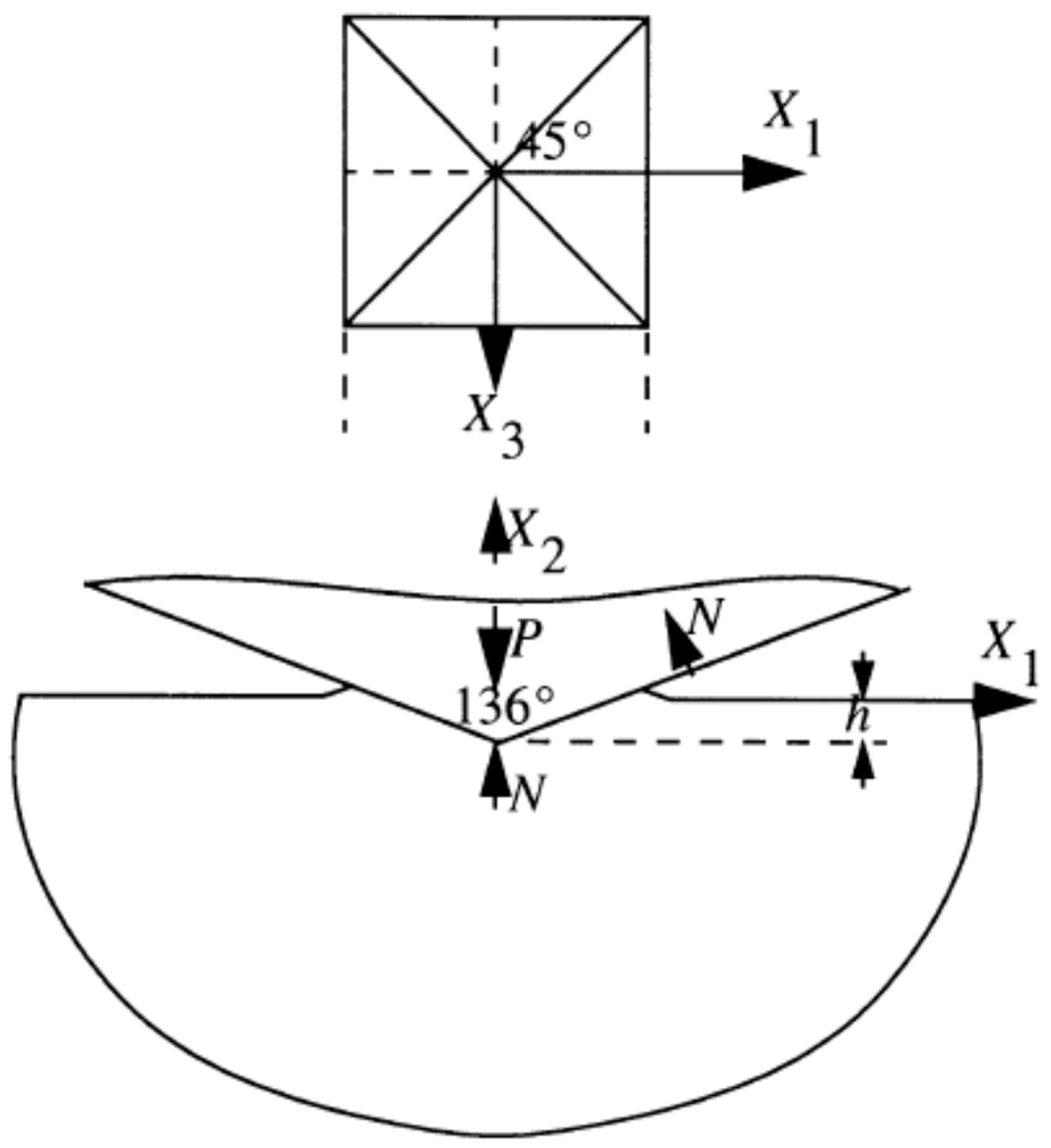
Figure 2.
Normalized hardness, = H/σy, and area ratio, c2, as functions of lnΛ, Λ defined according to Equiation (1). Schematic of the correlation of sharp indentation testing of elastic-ideally plastic materials. The three levels of indentation responses, I, II and III, are also indicated. Approximately, level II contact initiates at Λ = 3 level III contact at Λ = 900. The -curve flattens out at (approximately) Λ = 30.

Figure 3.
Finite element mesh used for the numerical calculations. In all cases a prescribed indentation depth was applied in the negative X2-direction. The figure shows mesh details close to the region of contact.
Figure 3.
Finite element mesh used for the numerical calculations. In all cases a prescribed indentation depth was applied in the negative X2-direction. The figure shows mesh details close to the region of contact.
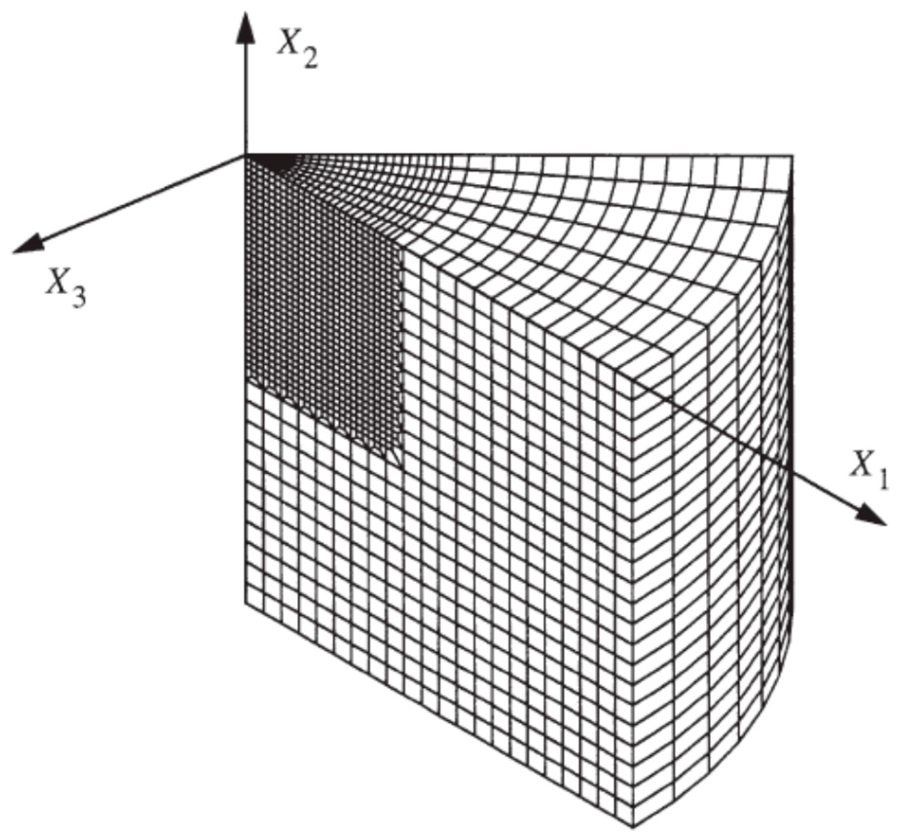
Figure 4.
Schematic of the pre-indentation loading. u is the prescribed radial displacement at the outer surface generating applied (residual) stresses.
Figure 4.
Schematic of the pre-indentation loading. u is the prescribed radial displacement at the outer surface generating applied (residual) stresses.
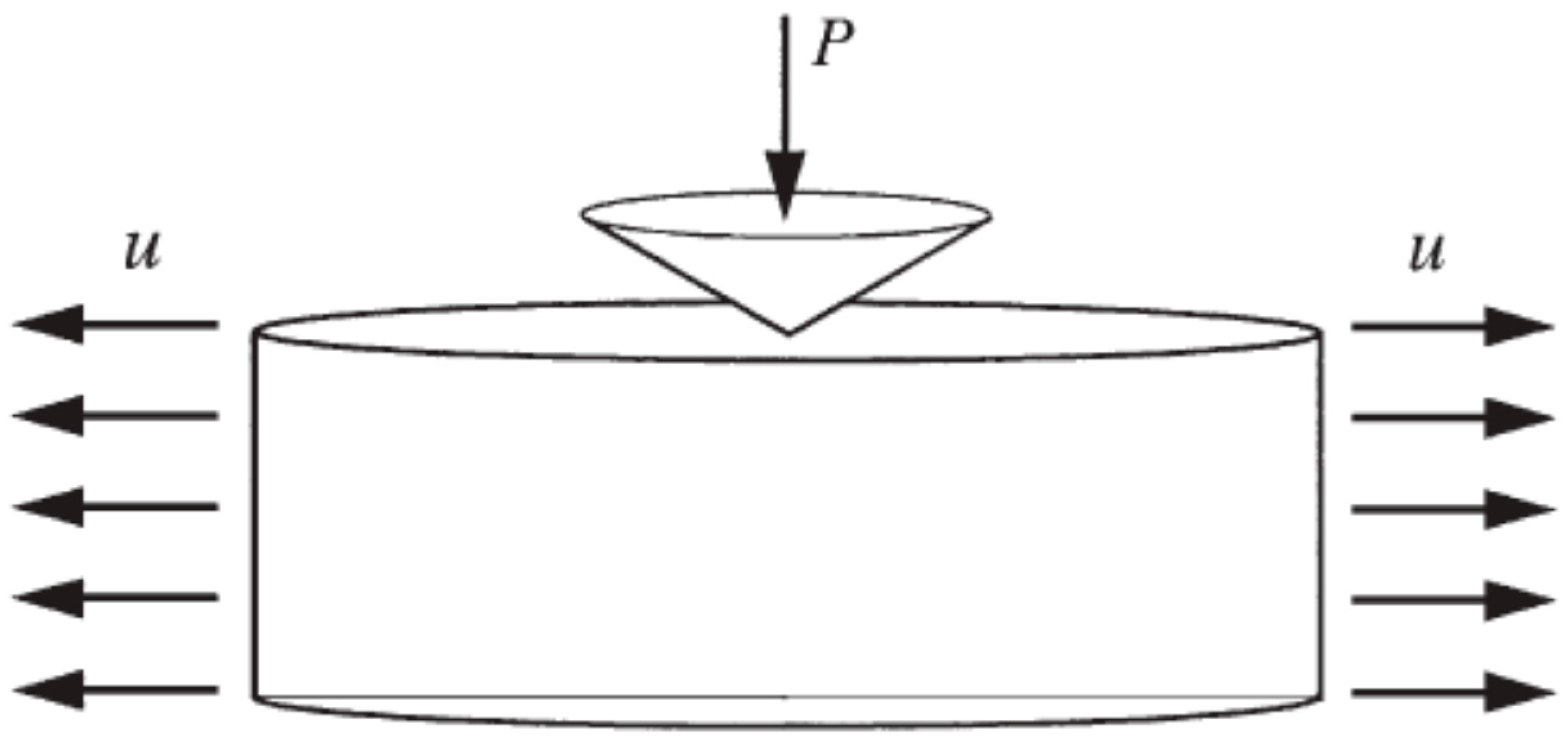
Figure 5.
Nondimensionalized hardness, H/H0, as a function of the nondimensionalized equi-biaxial residual stress field, σres/σy, at Vickers indentation. The results are pertinent to σy = 200 MPa. (- - -), H/H0 = 1. (o), numerical results for different values on σres/σy.
Figure 5.
Nondimensionalized hardness, H/H0, as a function of the nondimensionalized equi-biaxial residual stress field, σres/σy, at Vickers indentation. The results are pertinent to σy = 200 MPa. (- - -), H/H0 = 1. (o), numerical results for different values on σres/σy.

Figure 6.
Nondimensionalized hardness, H/H0, as a function of the nondimensionalized equi-biaxial residual stress field, σres/σy, at Vickers indentation. The results are pertinent to σy = 400 MPa. (- - -), H/H0 = 1. (o), numerical results for different values on σres/σy.
Figure 6.
Nondimensionalized hardness, H/H0, as a function of the nondimensionalized equi-biaxial residual stress field, σres/σy, at Vickers indentation. The results are pertinent to σy = 400 MPa. (- - -), H/H0 = 1. (o), numerical results for different values on σres/σy.
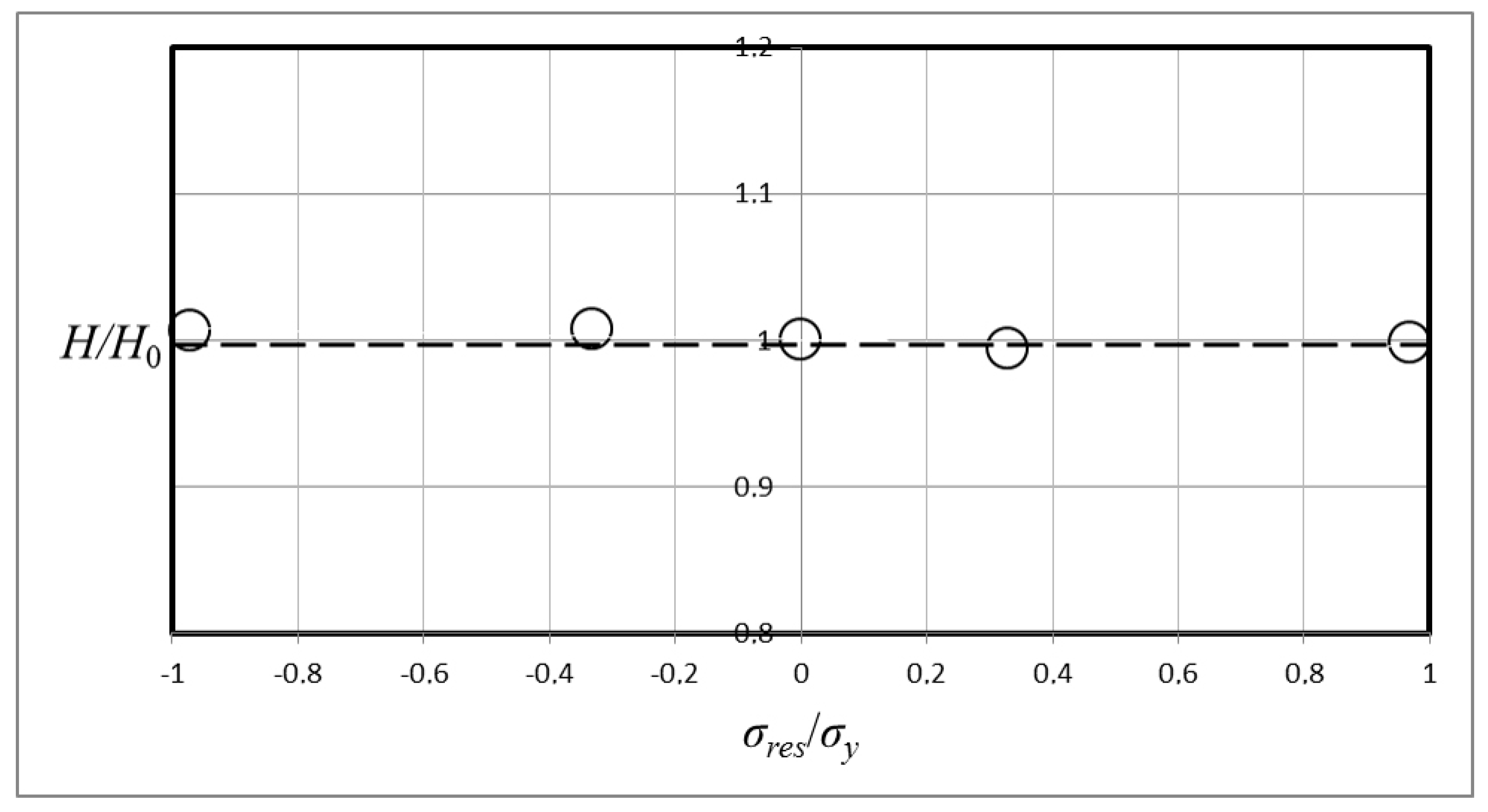
Figure 7.
Normalized hardness, H/σy, as a function of the nondimensionalized equi-biaxial residual stress field, σres/σy, at cone indentation with β = 22°. The results are pertinent to indentation of an elastic-ideally plastic material with ln Λ = 5 where Λ is defined according to Equation (1). (- - -), Equation (16). (o), numerical results for different values on σres/σy. The results are taken from Rydin and Larsson [9].
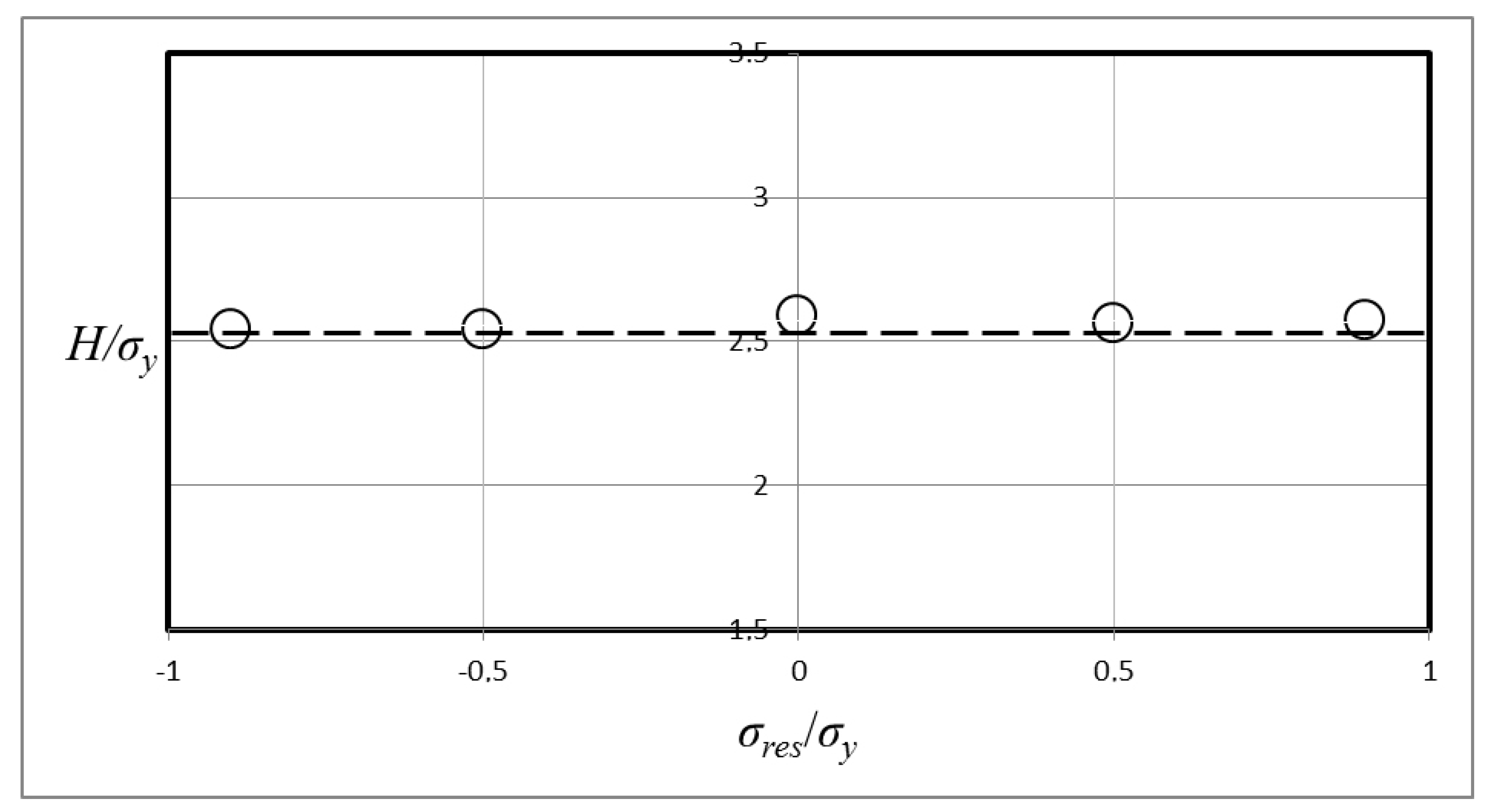
Figure 8.
Normalized hardness, H/σy, as a function of the nondimensionalized equi-biaxial residual stress field, σres/σy, at cone indentation β = 22°. The results are pertinent to indentation of an elastic-ideally plastic material with ln Λ = 3 where Λ is defined according to Equation (1). (- - -), Equation (16). (o), numerical results for different values on σres/σy. The results are taken from Rydin and Larsson [9].
© 2017 by the author. Licensee MDPI, Basel, Switzerland. This article is an open access article distributed under the terms and conditions of the Creative Commons Attribution (CC BY) license (http://creativecommons.org/licenses/by/4.0/).
Share and Cite
MDPI and ACS Style
Larsson, P.-L. On the Invariance of Hardness at Vickers Indentation of Pre-Stressed Materials. Metals 2017, 7, 260. https://doi.org/10.3390/met7070260
AMA Style
Larsson P-L. On the Invariance of Hardness at Vickers Indentation of Pre-Stressed Materials. Metals. 2017; 7(7):260. https://doi.org/10.3390/met7070260
Chicago/Turabian StyleLarsson, Per-Lennart. 2017. "On the Invariance of Hardness at Vickers Indentation of Pre-Stressed Materials" Metals 7, no. 7: 260. https://doi.org/10.3390/met7070260
Note that from the first issue of 2016, this journal uses article numbers instead of page numbers. See further details here.