Article

Effects of Welding Speed on Microstructure and Mechanical Property of Fiber Laser Welded Dissimilar Butt Joints between AISI316L and EH36

1
The State Key Laboratory of Digital Manufacturing Equipment and Technology, School of Mechanical Science and Engineering, Huazhong University of Science & Technology, Wuhan 430074, China
2
George W. Woodruff School of Mechanical Engineering, Georgia Institute of Technology, Atlanta, GA 30332, USA
3
School of Materials Science and Engineering, Huazhong University of Science and Technology, Wuhan 430074, China
*
Author to whom correspondence should be addressed.
Metals 2017, 7(7), 270; https://doi.org/10.3390/met7070270
Submission received: 5 May 2017 / Revised: 6 July 2017 / Accepted: 7 July 2017 / Published: 13 July 2017

Abstract

:
Fiber laser welding of dissimilar materials between AISI316L austenitic stainless steel and EH36 ship steels were conducted. Then the effects of welding speed on microstructure and mechanical characterization of the welded joint were investigated. Optical microscopy, Scanning Electron Microscopy (SEM), and X-ray Diffraction (XRD) were used to analyze the microstructure. Microhardness testing, transverse tensile strength, and impact tests at the temperature of −40 °C were performed to study the mechanical properties. The martensite phase formed due to the rapid cooling rate during laser welding and low Creq/Nieq ratio. The coarse martensite grains in the center seam are transformed to finer martensite grains as the welding speed increases resulting in the higher cooling rate. The microhardness of joints was about 350 HV0.3, which was twice that of the base metal because of the formation of the martensite phase. When the welding speed was 0.6 m/min, fewer defects were found, and tensile testing indicated overmatching of the weld metal relative to the base metal. In addition, the joints also exhibited better ductility and impact toughness.

1. Introduction

The modern shipbuilding industry has exacting requirements for tonnage and speed of a ship. High strength and good corrosion resistance are vital for a ship due to the abominable working conditions. Therefore, high strength structure steel is widely applied in shipbuilding. As a type of important high strength low alloy (HSLA) structure steel, EH36 ship steel has attracted a lot of research for the advantages of low carbon, low alloy, and high strength [1,2,3,4,5,6,7,8,9]. However, EH36 steel exhibits poor corrosion resistant when it is exposed for long periods in a seawater environment. The stainless steel is a good choice to deal with this problem for its high toughness and corrosion resistance, except for its high cost [10,11,12,13]. When considering performance and economy advantages compared with a single material, welding of dissimilar metals (like HSLA steel and stainless steel) in shipbuilding provides greater flexibility for the designer and engineer. In this work, EH36 high strength steel and 316L stainless steel were joined considering economic benefits and high corrosion resistance whilst retaining high weldability [14,15,16]. Kacar et al. [14] studied seam quality of the 316L stainless steel and DIN-P355GH grade vessel steel joined by an explosive welding technique. They found that the mechanical aspects of the seam are improved compared to the parent metal. Ranjbarnodeh, E. et al. [17] studied the influence of heat input on the temperature distribution of weld zone between stainless steel and carbon steel through numerical simulation and verification experiments. Kaya et al. [18] investigated the mechanical properties of the weld interface of Grade A ship steel and AISI316L austenitic stainless steel. Consequently, mechanical properties of Grade A ship steel were increased by explosive welding with AISI316L austenitic stainless steel. Rao et al. [19] investigated microstructure, hardness, and residual stress distribution of dissimilar metal electron beam welds between maraging steel and high strength low alloy steel. Bansal, A. et al. [20] investigated the dissimilar weld between SS-316 and mild steel using microwave hybrid heating. They found the optimum temperature required for joining was 1360 degrees centigrade, and the mechanical properties were improved because of the formation of dendritic and carbides. All of these studies indicate that welding of dissimilar metals is an effective method that can take advantages of each material and improve the mechanical properties of the welded seam. As it is known, the difference of chemical composition and physical properties is a big challenge for dissimilar metals welding [21,22,23]. Traditional welding technology (like arc welding) usually has higher heat input which will lead to larger dimensions of seam and distortion. Moreover, multi-pass welding must be implemented in welding of thick heavy structure because the penetration is limited for traditional welding techniques.
High power fiber lasers offer a faster welding speed, lower heat input, lower panel distortion, and deeper penetration compared with traditional arc welding [24,25,26,27]. Hence, it is increasingly adopted in the shipbuilding industry for the major motivation of reducing distortion, as it is estimated that between 20% and 30% of the man hours used in shipbuilding is due to reworking caused by welding distortion [28]. Parkes D et al. [22] evaluated the microstructure and fatigue properties of welded joints made with fiber laser welding on high strength low alloy and DP980. Then found that due to the fast cooling during fiber laser welding (FLW), the narrow fusion zone (FZ) was composed of a highly martensitic structure. Wu et al. [29] studied the joint of dissimilar metals between ferritic stainless steel and low carbon steel that were welded by a laser beam. They found that the microstructure of weld metals consisted of few ferrite and lath martensite in the carbon steel (CS) steel. All above researches concerned microstructure and mechanical properties of laser welding joints of dissimilar metals, and some methods were proposed for the challenges of difference in thermal conductivity and surface tension of the base metals. Nevertheless, laser power, welding speed, defocusing amount, and other processing parameters play important roles on the microstructure and mechanical properties of the welding bead [30,31,32,33]. Zhang et al. [11] studied the effects of welding speed, focal position and shielding gas on joint geometry, they found that a focal position below the specimen surface was preferable. Furthermore, there is a critical region of the welding speed for achieving good full penetration joints. The influence of laser power, defocusing amount, and welding speed on the microstructure and mechanical properties of the welded seam was investigated [34,35]. Their research indicated that welding speed was one of the important processing parameters that played significant roles in the microstructure and mechanical properties of the welded seam.
In this paper, the effects of welding speed on the microstructure and mechanical property of the fiber laser welded dissimilar butt joints between AISI316L and EH36 ship steels were studied. Welding speed was selected as the main parameter for the reasons that: (a) welding speed has a significant relationship with heat input and cooling rate which greatly influences the microstructure; (b) welding speed plays an important role in welding productivity. Optical microscopy, Scanning Electron Microscopy (SEM), and X-ray Diffraction (XRD) were used to analyze the microstructure. Then microhardness, transverse tensile strength, and impact tests at the temperature of −40 °C were performed to study the mechanical properties at different welding speed.

2. Materials and Experimental Method

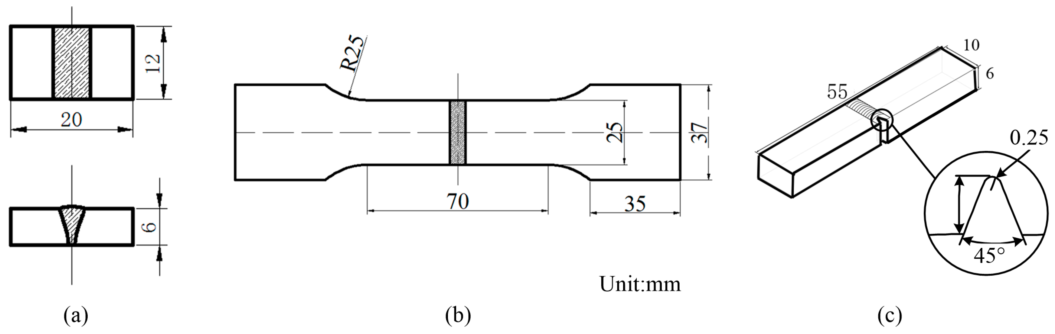
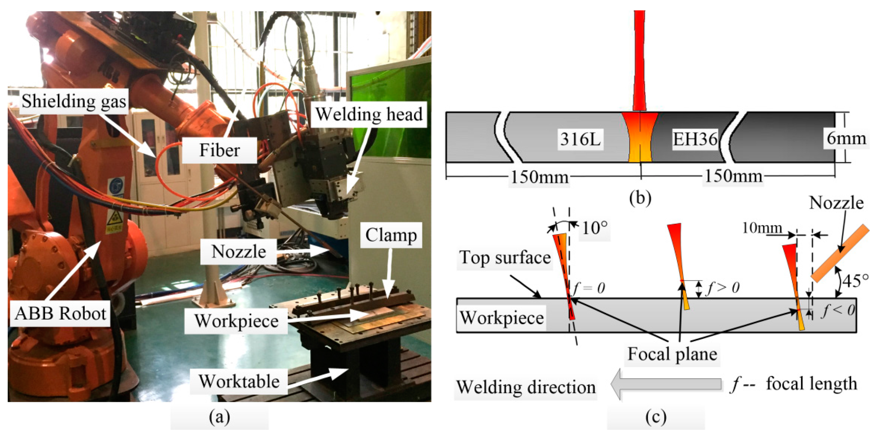
2.1. Laser Welding Specimen

The materials used for fiber laser welding were 6 mm thick AISI316L austenitic stainless steel plate and 6 mm thick EH36 steel. The dimensions of the specimen were 150 mm × 100 mm × 6 mm. The butt welding performed was illustrated in Figure 1b. To control the misalignment and weld gap accurately, the plates were carefully polished and faced. The specimens had been pretreated or degreased with acetone before welding in order to eliminate the interference from oxidation film and prevent the welding bead being polluted by oil. Table 1 shows the chemical compositions of the base metals in weight percent.

2.2. Procedure of Laser Welding

Figure 1a demonstrates the laser welding system utilized in this work. The laser welder adopted was the IPG YLR-4000 ytterbium-doped fiber laser (IPG Photonics, Oxford, MS, USA), and its typical BPP (Beam Parameter Product) was 22 mm × mrad. The maximum output power of the continuous-wave fiber laser was 4000 W. The laser was delivered through the optical fiber to the laser welder head, where a focusing lens with the focal length of 250 mm was installed. The wavelength is 1.07 μm and the diameter of light spot on the upper surface of the specimen was 0.3 mm. The shielding gas was argon with a flow rate of 25 L/min. Figure 1b shows the schematic of the laser welding of the 316L stainless steel/EH36 steel. The fiber laser beam welding parameters were given in Table 2.
The electric cutting machine STDX600 (Taizhou Machine Tool Plant, Taizhou, China) was applied to cut test samples of microstructure and the mechanical properties of the joints from each weldment. The dimensions of the transverse sample are shown in Figure 2a. The microstructures of the joints were observed by optical microscope (OM). To obtain a clear image of the bead profile, all welding seams were initially polished with suitable sandpapers and diamond paste, etching with the etchant Kalling’s No. 1 (1.5% CuCl2 (cupric chloride) + 39.5% HCl (hydrochloric acid) + 26.0% C2H5OH (absolute ethyl ethanol) + 32.9% of distilled water) and cleaned by anhydrous alcohol before observing. The X-ray diffraction (XRD) (D8 Advance) and scanning electron microscope (SEM) (Helios NanoLab G3 CX) (FEI, Brno, Czech Republic) were applied to confirm the microstructural features.
A micro-hardness survey was conducted across the weld beads of the transverse samples employing a Vickers micro-hardness testing machine (HVS-1000A) (HUAYIN, Wuhan, China). All of the micro-hardness data were obtained at a load of 300 gf for a duration of 15 s. To avoid interaction effect, the distance between two consecutive indentations was set as 0.2 mm. Tensile specimens are prepared as shown in Figure 2b (the unit is mm) to evaluate the tensile strength of the joints at room temperature. Three replicates for tensile testing were prepared to minimize errors. Tensile testing was carried out using 100 kN, using an electromechanical controlled universal testing machine (AG-IS 100KN) (SHIMADZU, Kyoto, Japan) at a cross-head speed of 5 mm/min. The fracture surfaces were examined using a scanning electron microscope (SEM) (FEI, Brno, Czech Republic).
Charpy impact specimens were prepared to the dimensions (the unit is mm) shown in Figure 2c to evaluate the impact toughness of the weld metal, hence the notch was placed at the weld center. Impact testing was conducted at a temperature of −40 °C using a pendulum-type impact testing machine (PSW750, ZWICK, Ulm, Germany). The amount of energy absorbed in the fracture was recorded, and is defined as the impact toughness of the material.

3. Results and Discussion

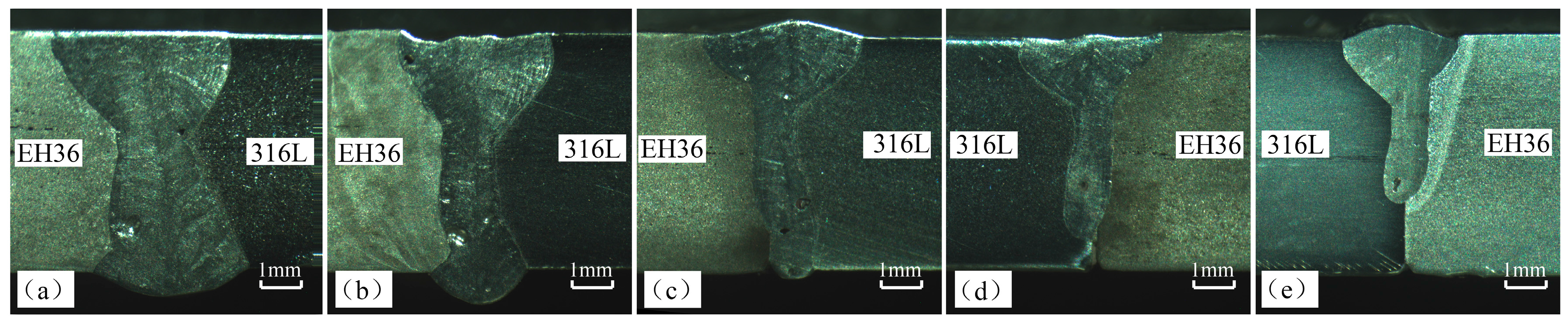
3.1. Appearance of the Weld Cross Section

The fiber laser beam traveled along the center of the welding bead, and then the 316L stainless steel and the EH36 steel were simultaneously irradiated by the fiber laser beam. Figure 3 demonstrates the influence of welding speed on appearance of the cross section of the joint. The top surface is slightly sunken at a low welding speed, as the welding speed increases, the top surface becomes convex and narrower. The width and penetration of the welding bead decreases obviously as the welding speed increases form 0.4 m/min to 1.2 m/min, the joints appearance varied from full penetration to partial penetration. It was found that the welding speed is lower than 0.8 m/min; the weld defect was in the form of excess penetration because of the corresponding higher heat input.
The heat input can be calculated from heat input = η(LP/WS), where LP and WS present laser power and welding speed respectively, and η is the welding efficiency, which is a constant of 0.8 [36,37]. So when the welding speed increases from 0.4 m/min to 1.2 m/min, the heat input reduces from 479.8 J/mm to 200 J/mm. When the welding speed is faster than 1.0 m/min, the defect of in-completed penetration occurred. In addition, it can be found that the macro cross section of the joint isn’t symmetrical on both sides of the welding direction. Actually, thermal conductivity of AISI316L is about 15 W/(m·K), while that of EH36 is about 40 W/(m·K) [38,39]. The melting of 316L is more significant than EH36 because the thermal conductivity of EH36 is higher than that of 316L. Higher thermal conductivity tends to rapidly dissipate heat away from the weld, thus leading to difficulties in reaching the melting temperature. Figure 3 also shows that large pores were trapped at the bottom of the weld at high welding speeds (>0.8 m/min). A sound appearance was obtained when the welding speed was about 0.8 m/min. Generally, an appropriate joint shape means better seam quality.

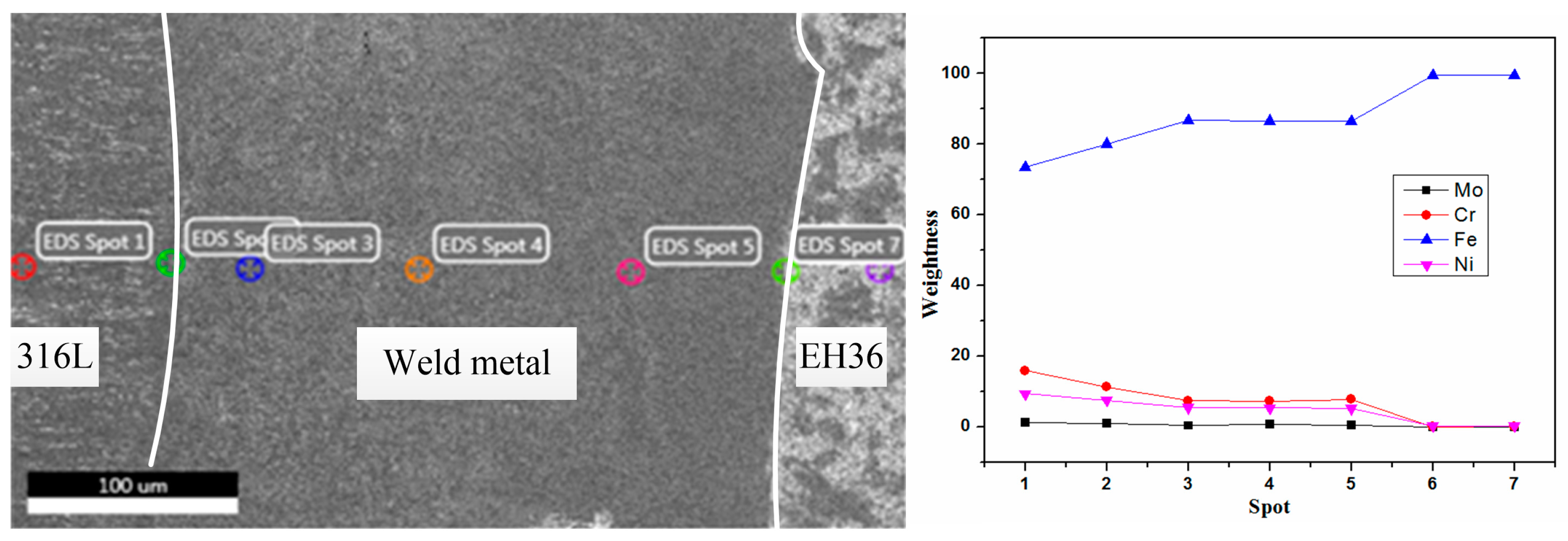
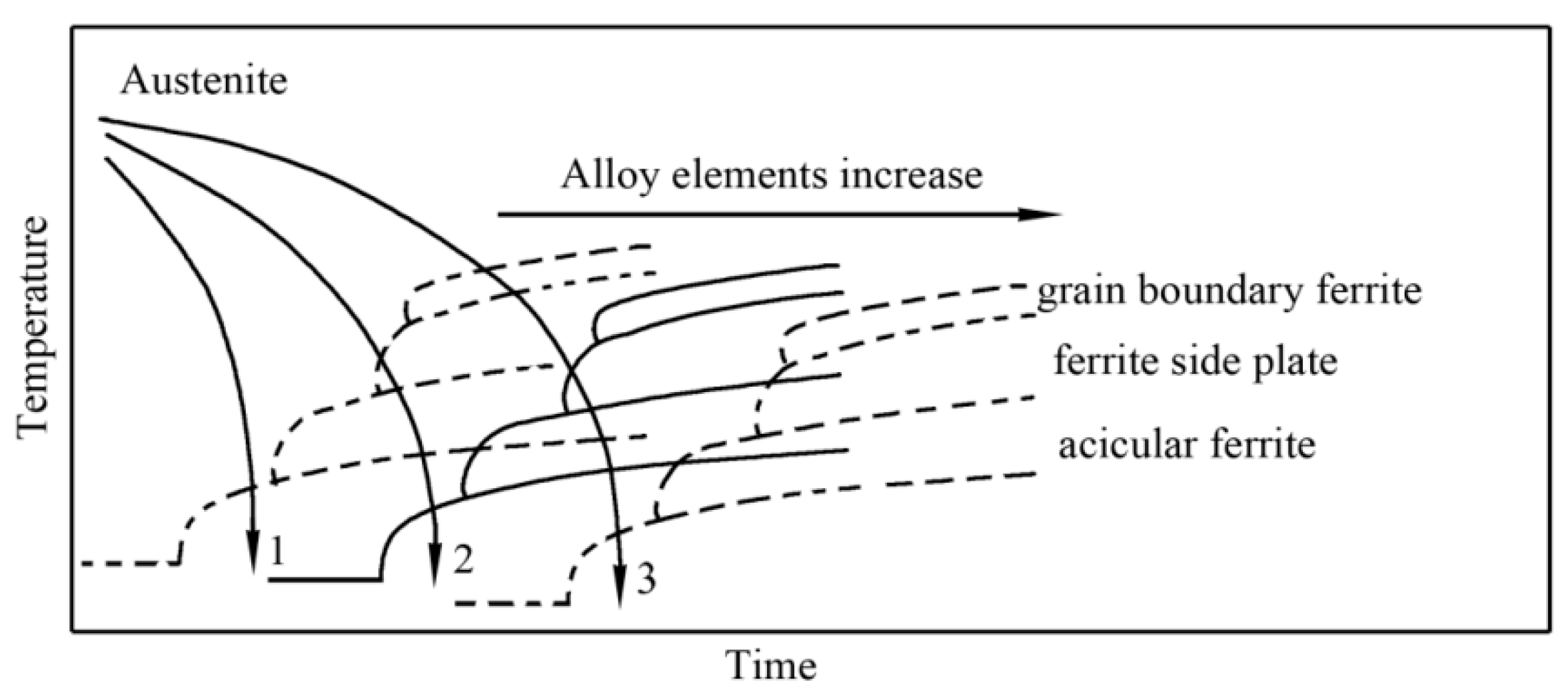
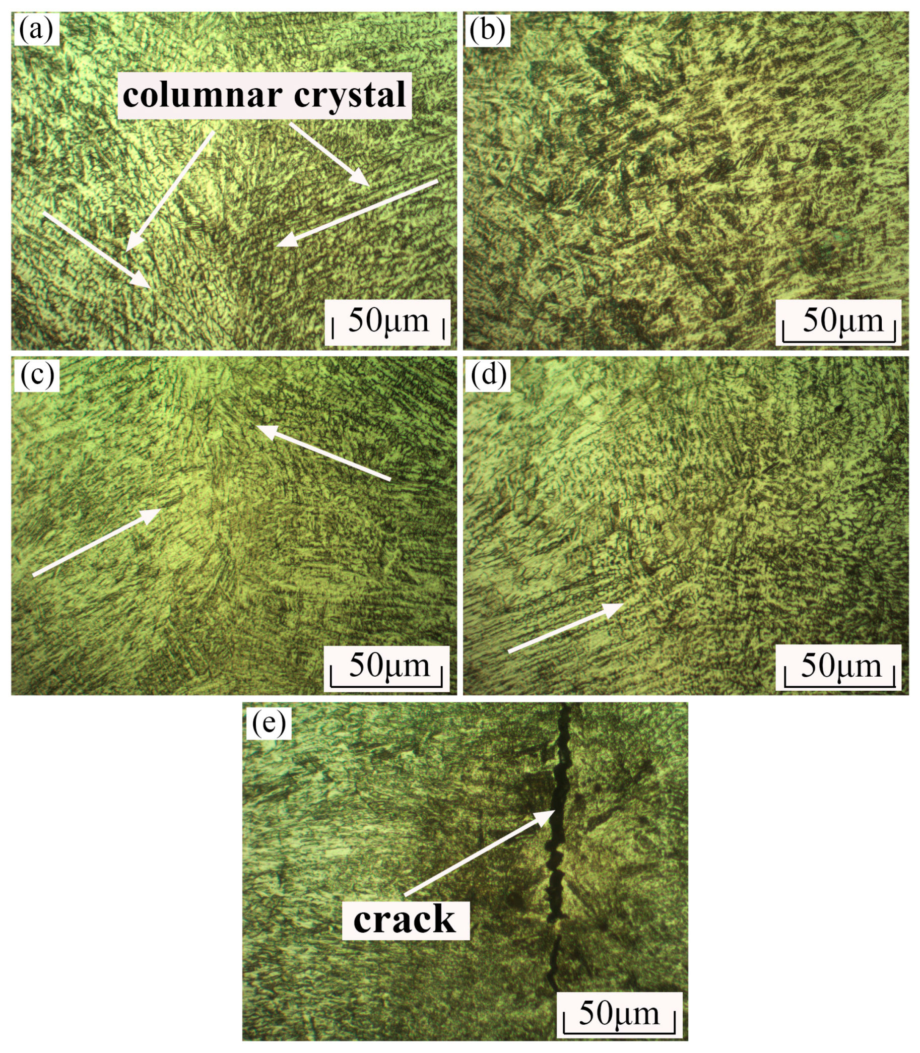
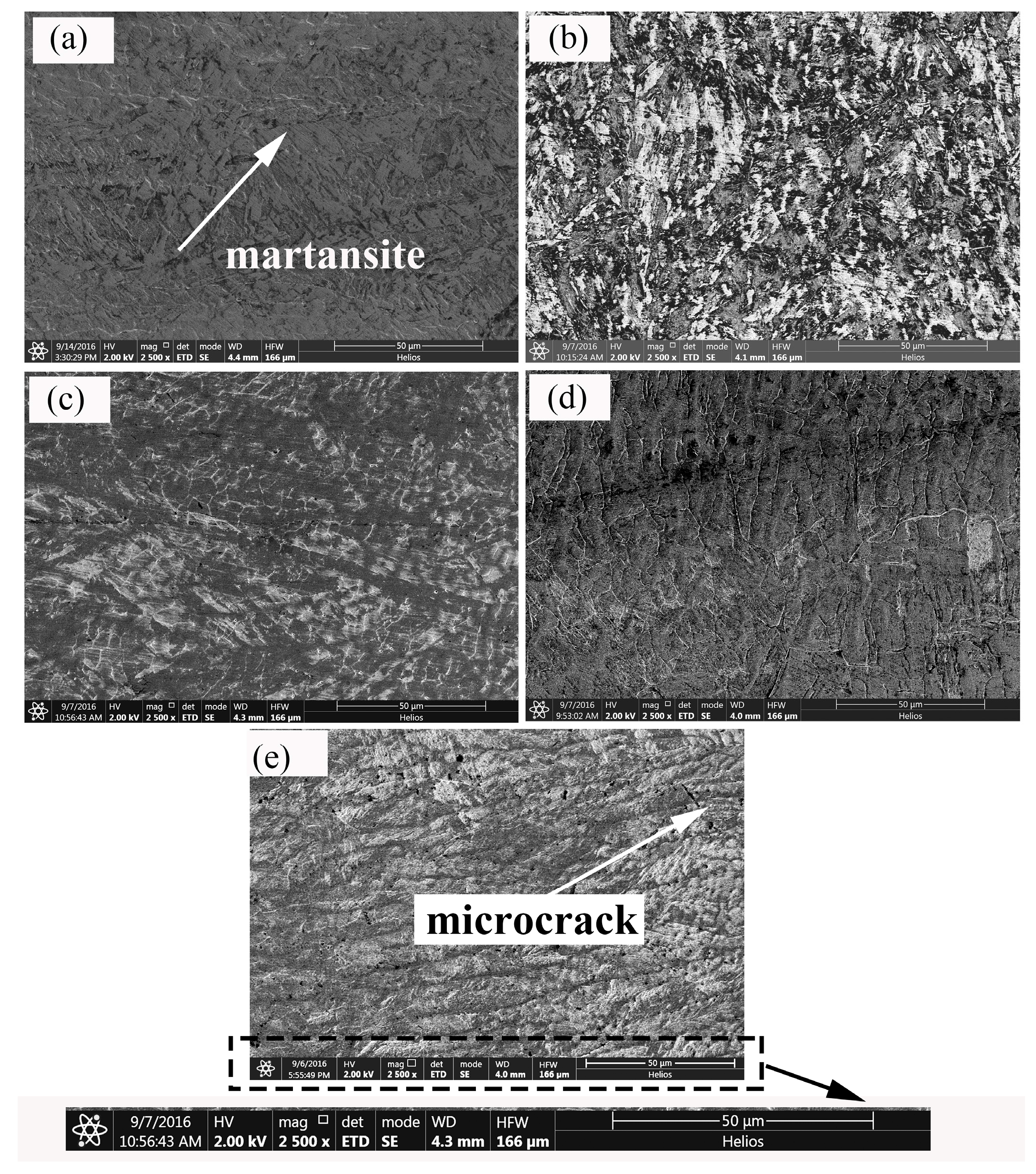
3.2. Microstructure of the Joint

Kotecki and Siewert [40] estimated the phase constituents of welding seam according to a Schaeffler diagram. In this paper, the equivalents of Ni and Cr were calculated by Formulas (1) and (2) respectively. In the formulas, Nieq and Creq represent the equivalents of Ni and Cr. As Figure 4 shows the Energy Dispersive Spectroscopy (EDS) is conducted across the center seam. Phase constituents of the center seam were identified by XRD. Figure 5 shows that the major phase is martensite.
Ni eq = Ni + 30 C + 0.5 Mn 8.01 ,
Cr eq = Cr + Mo + 1.5 Si + 0.5 Nb 6.00 .
The results indicate that the center seam will only have martensite. Figure 6 demonstrates that the CCT (Continuous Cooling Transformation) curve will move to the direction of longer time and lower temperature with increasing content of alloy elements. As the welding speed increases, the cooling rate is higher, thus the cooling curve moves. The martensite phase transformation occurred as the content of alloy elements (especially Ni and Cr) and the cooling rate are high enough; then no retained austenite remains.
Figure 7 shows the microstructure of the center seam with different welding speeds. The white arrows represent the direction of grain growth. The columnar crystal was the main crystal type in Figure 7a. The crystal contacted in the center of the seam. As the welding speed increased from 0.4 m/min to 1.2 m/min, the grain size was refined. This is attributed to the fact that low energy input which can reduce the high-temperature residence time and decrease the tendency of grains’ growth. It indicates that the welding speed has important influence on the microstructure. There is an obvious crack in the center of the seam as shown in Figure 7e. The size of the crack is about 8 μm × 200 μm. The crack is formed due to the increase of welding speed results in the increase of cooling rate. The diffusion of elements is incomplete because of the fast cooling rate, which leads to the composition segregation and stress concentration.
The SEM morphologies of the center seam with different welding speeds are shown in Figure 8. The lath martensite formed after phase transformation. There are some microcracks in Figure 8e because of the higher welding speed and high cooling rate. The formation mechanism of microcracks would be studied in the further investigation.

3.3. Mechanical Property and Fracture Behaviour

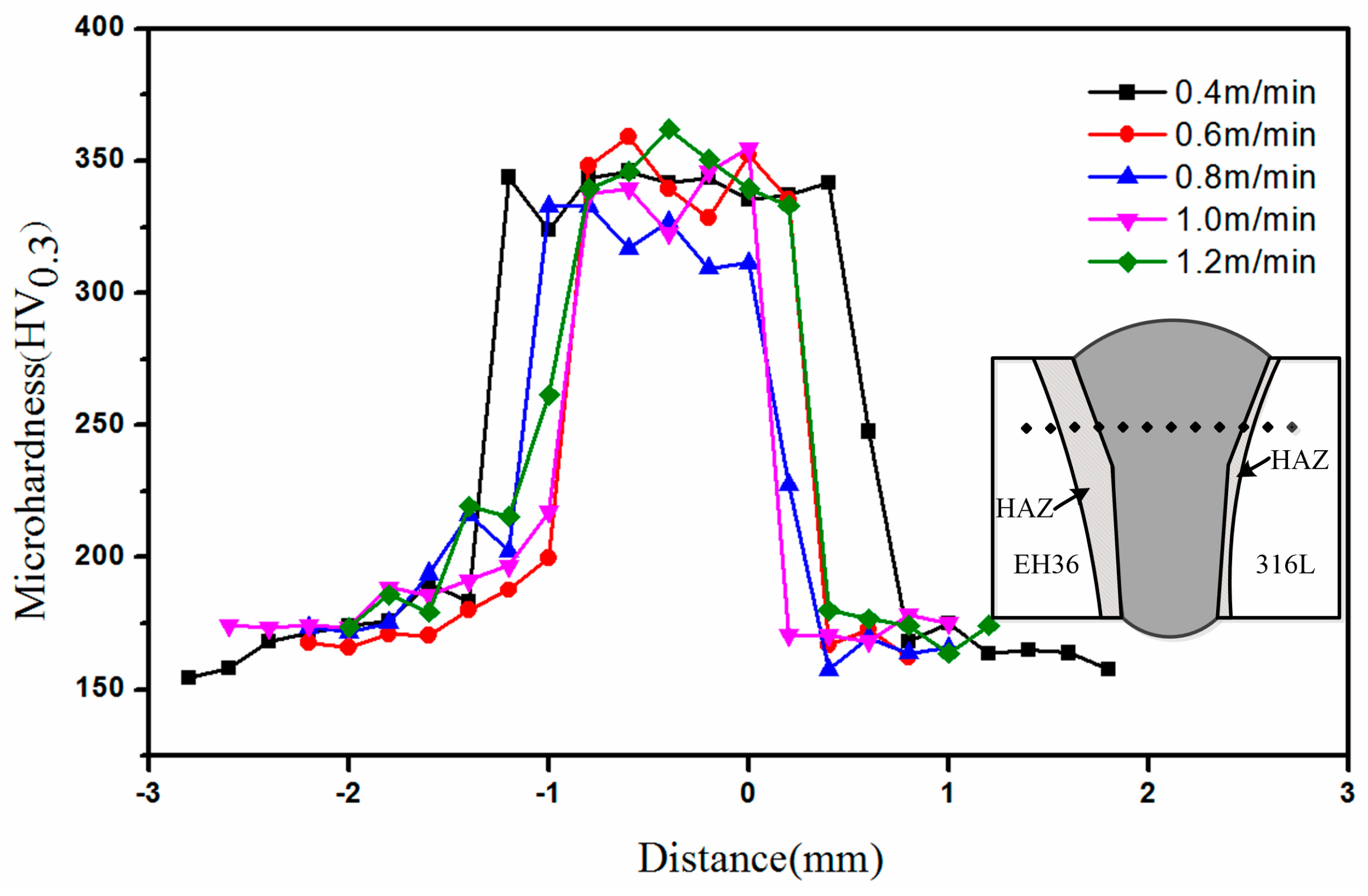
3.3.1. Microhardness

Figure 9 shows the microhardness profile of the joint cross section. In the weld, the value of microhardness fluctuates slightly across the weld; it was about 350 HV0.3 which was two times higher than that of the base materials (it is about 180 HV0.3). The value of microhardness in the heat affect zone (HAZ) of EH36 is about 240 HV0.3. The higher microhardness in center seam was attributed to the formation of harder microconstituents—such as martensite and the fine grain. It indicated that welding speed has obvious influence on the weld cross section microhardness. As the welding speed increased, the microhardness decreased initially and then increased. The highest microhardness was corresponding to 1.2 m/min and the lowest was 0.8 m/min. The possible reason is associated with welding heat input, because the welding speed 0.4 m/min has a heat higher input than that of the welding speed 0.6 m/min to 1.2 m/min, respectively. Further analysis showed that the welding speed 0.4 m/min has a result of a slower cooling rate than the welding speed 0.6 m/min to 1.2 m/min, respectively. The grain size was refined as the welding speed increases, which is attributed to the fact lower heat input which can reduce the high-temperature residence time and decrease the tendency of grains’ growth. At the same time, there is sufficient time for the diffusion of alloying element at low welding speeds.

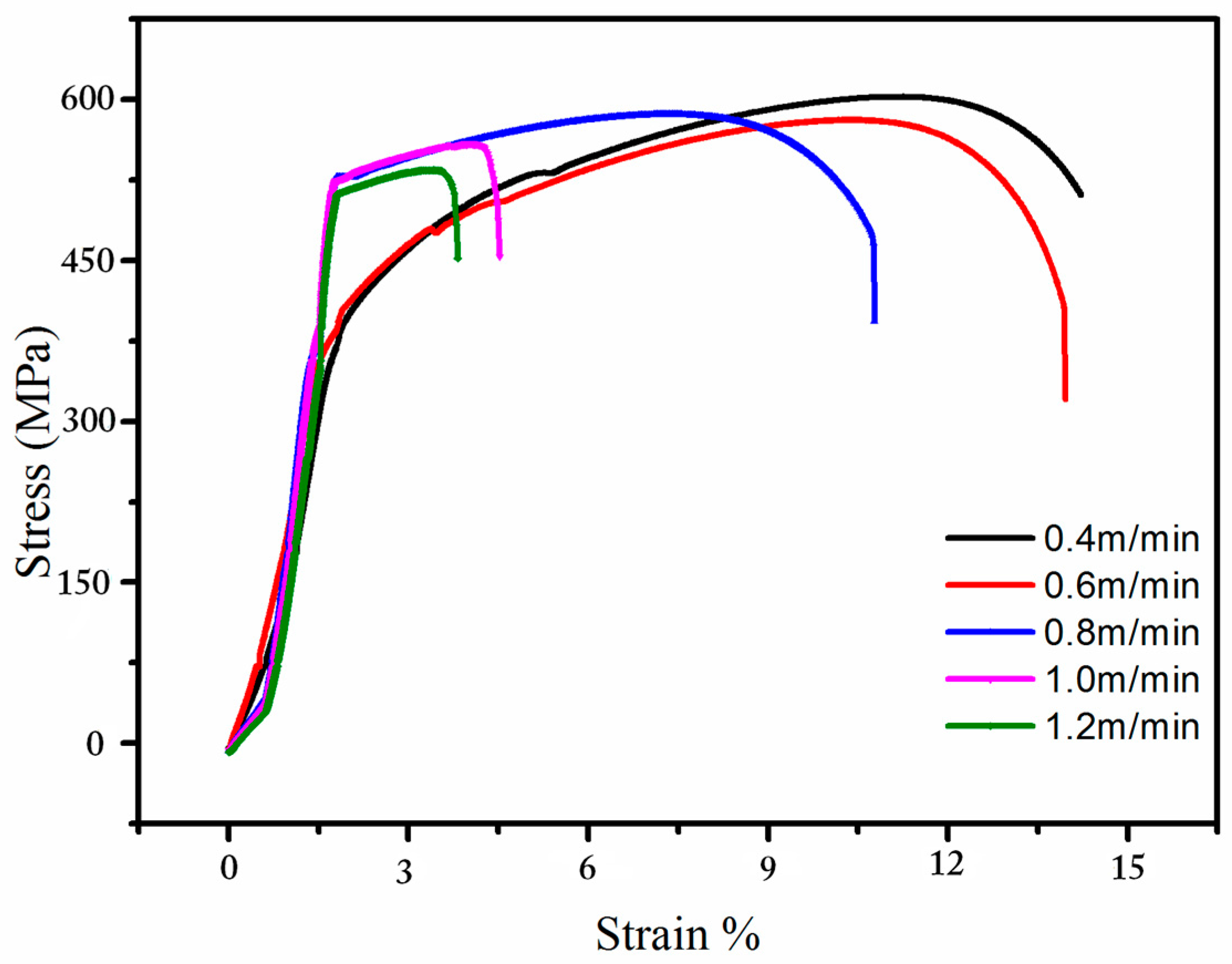
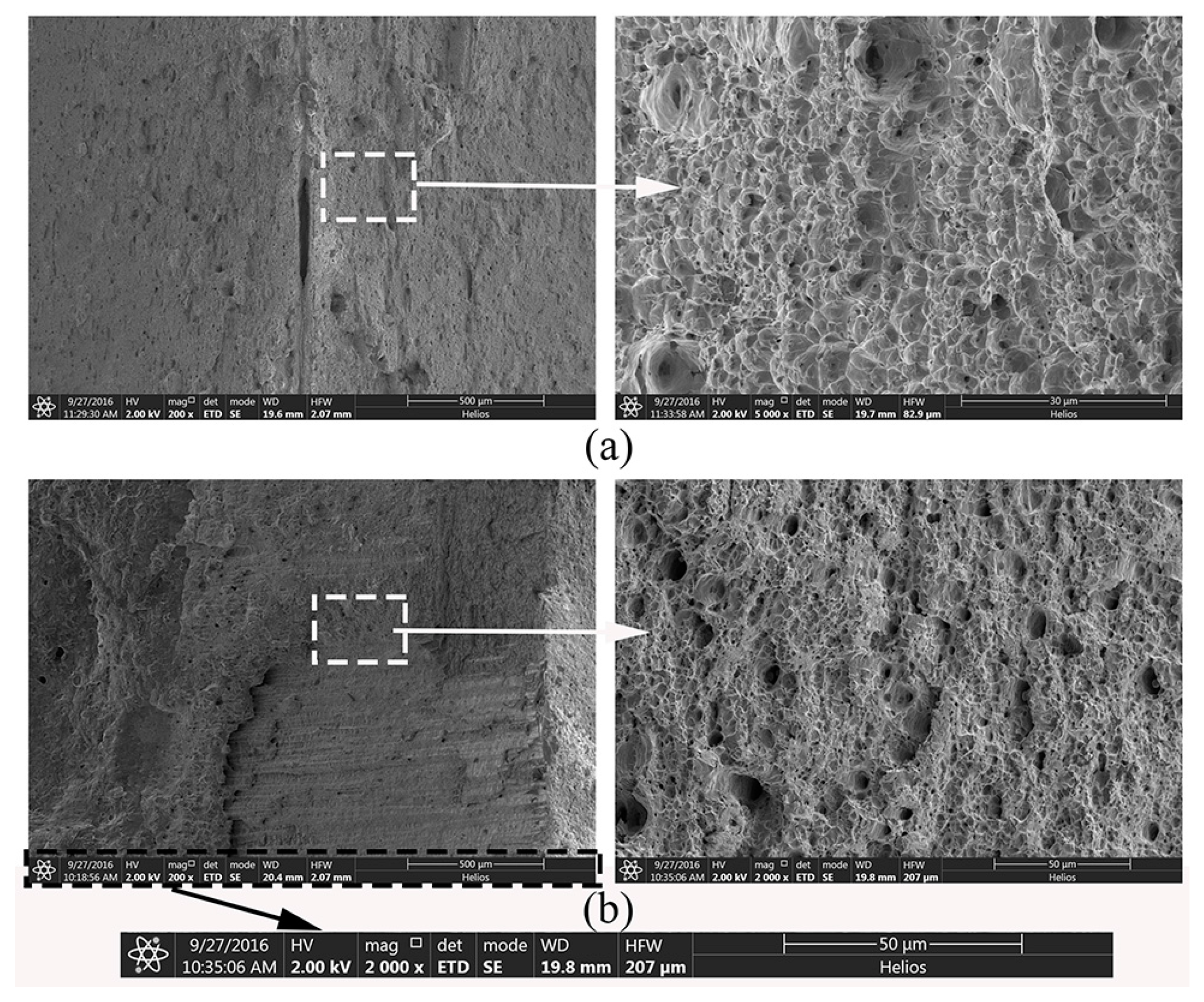
3.3.2. Tensile Properties

The load-displacement curves are plotted in Figure 10, which shows the stress-strain curves of the welds at different welding speeds. Table 3 demonstrates the tensile strength of dissimilar metal laser welding samples. The tensile strength is about 520 MPa. Numbers 3, 4, and 5 failed in the weld zone, while the others failed in the base metal of EH36. The tensile strength of the weld joint with full penetration is better than that of the dissimilar metals. With the welding speed increasing, the tensile strength of the weld joint decreased, the failures occurred on the weld joint zone. In addition, the Numbers 3, 4, and 5 exhibited similar tensile strength although the significant incomplete penetration with the welding speed increasing as Figure 3 shows. Due to the presence of a significant incomplete penetration in the joint obtained with a welding speed of 1.2 mm/min, the corresponding tensile strength can be reasonably similar to those of the other samples if the cross section area considered in the calculation of stress took into account the presence of the incomplete penetration. This means that the cross section area used was 6 × 25 mm2 for the welds with a complete penetration, and about 4 × 25 mm2 (the incomplete penetration seems about 2 mm from Figure 3e) for the weld joint obtained with a welding speed of 1.2 mm/min.
The defect of in-completed penetration (Figure 3) and the porosity and pores generated in the laser welding process were responsible for lowering its strength. The fractographic analysis is shown in Figure 11. Figure 11a demonstrates the fracture surface of the EH36 base material. The fracture surface shows the typical dimpled ductile fracture surface. Figure 11b shows the fracture surfaces of weld specimens. The cup and cone phenomenon (dimple fracture) was found. There are some pores in the failure surfaces.

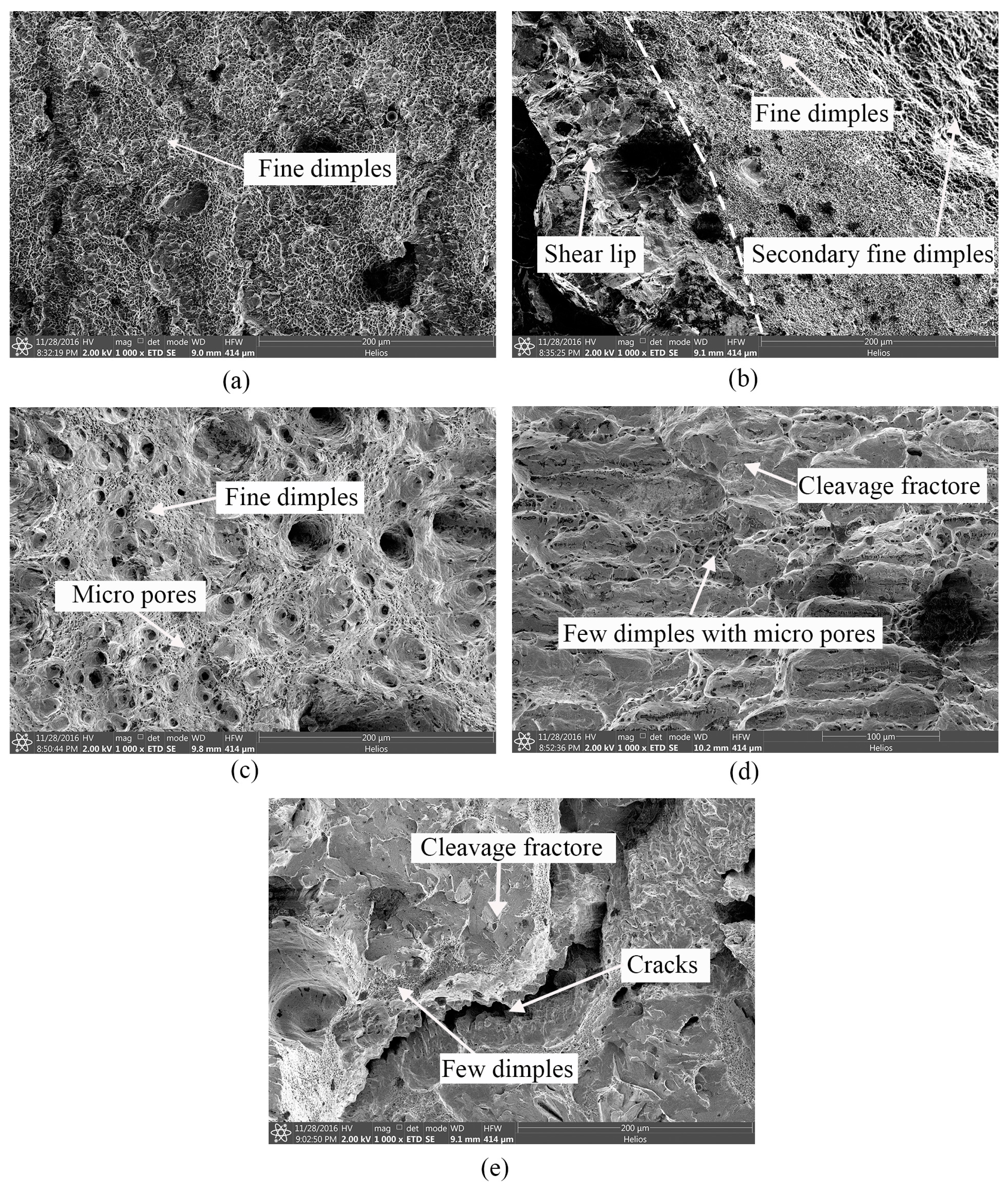
3.3.3. Impact Toughness

Impact toughness of weld metal was evaluated at the temperature of −40 °C using standard Charpy V-notch specimens [41]. The Charpy specimens were prepared with notch roots in the weld metal shown as Figure 2c. Table 4 shows the results of the Charpy impact testing. Table 4 shows that sample 3 exhibited the highest absorbed impact energy of 73.9 J, followed by sample 2 which is 42.9 J. Whereas the others’ impact toughness were less than 40 J. As the welding speed increases, the impact strength was improved obviously. It can be attributed to the fact that the high welding speed leads to low heat input and a high cooling rate. Therefore, the grains were refined. The impact energy of sample 4 and 5 decreased, as attributed to the in-completed penetration defects when the welding speed is too high which lead to lower heat input. The scanned fractographs of the fracture surface of charpy v-notch impact tested specimens with different welding speed are shown in Figure 12. At higher magnification, fine dimples can be clearly seen in Figure 12a and few secondary dimples can be observed at the lip of dimples in Figure 12b. This could be the reason for the high impact strength with the welding speed of 0.8 m/min. Some micro pores can obviously be seen in Figure 12c, however, the size of dimple is smaller. Fracture morphology consists of cleavage facets and a few dimples of depth size can be seen in Figure 12d,e, which depict the type of mixed fracture mode. This may be the reason for the drop of impact energy absorption. Obvious cracks are exhibited in Figure 12d, which may be the reason for the lowest impact toughness. The dimple size exhibits a directly proportional relationship with the strength and ductility, i.e., if the dimple size is finer, the strength and ductility of the respective joint are higher and vice versa.

4. Conclusions

The effects of welding speed on microstructure and mechanical properties of fiber laser welded dissimilar metals between AISI316L austenitic stainless steel and EH36 ship steel joints were investigated. The following important conclusions were derived:
  • When the welding speed was lower than 0.8 m/min, the weld defect was in the form of excess penetration, while, the defect of in-completed penetration and pores occurred when the welding speed faster than 1.0 m/min. A sound seam appearance was obtained when the welding speed was about 0.8 m/min.
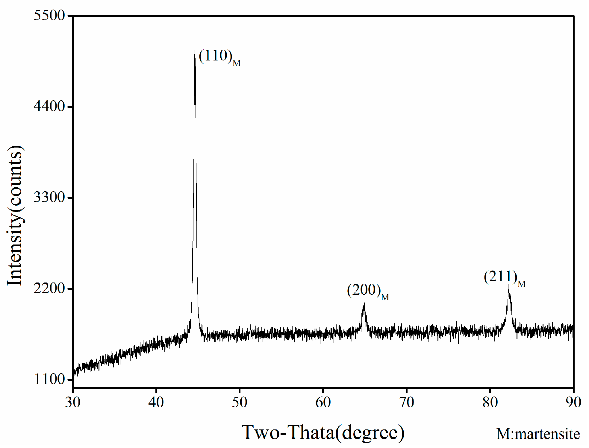
  • The major phase in the center seam was martensite because of the ratio of Nieq and Creq located in the martensite zone, and then the content of the alloy elements and cooling rate also lead to the formation of martensite.
  • The microhardness of joint fluctuates slightly along the weld across section, it is about 350 HV0.3, which is twice higher than that of base materials (it is about 180 HV0.3). This was caused by the formation of lath martensite. The value of microhardness in the heat affect zone (HAZ) of EH36 is about 240 HV0.3.
  • The tensile strength of the joint with full penetration is better than the dissimilar metals. The cup and cone phenomenon (dimple fracture) was found. The highest absorbed impact energy is 73.9 J. The impact toughness of the seam with different welding speed is acceptable. A sound seam with high mechanical properties can be obtained with higher welding speeds on the basis of full-penetration being accomplished. This can provide guidelines for the shipbuilding industry.

Acknowledgments

This research has been supported by the National Basic Research Program (973 Program) of China under grant No. 2014CB046703, the National Natural Science Foundation of China (NSFC) under Grant Nos. 51323009 and 51121062, the Fundamental Research Funds for the Central Universities, HUST: Grant No. 2016YXMS272. The authors also would like to thank the anonymous referees for their valuable comments.

Author Contributions

Longchao Cao and Qi Zhou conceived and designed the experiments; Longchao cao, Youmin Rong and Shaoning Geng performed the experiments; Ping Jiang, Gaoyang Mi and Longchao Cao analyzed the data; Xinyu Shao contributed reagents/materials/analysis tools; Longchao cao and Qi Zhou wrote the paper.

Conflicts of Interest

The authors declare no conflict of interest.

References

  1. Roepke, C.; Liu, S.; Kelly, S.; Martukanitz, R. Hybrid laser arc welding process evaluation on DH36 and EH36 steel. Weld. J. 2010, 89, 140–149. [Google Scholar]
  2. Lambert, A.; Drillet, J.; Gourgues, A.; Sturel, T.; Pineau, A. Microstructure of martensite-austenite constituents in heat affected zones of high strength low alloy steel welds in relation to toughness properties. Sci. Technol. Weld. Join. 2000, 5, 168–173. [Google Scholar] [CrossRef]
  3. Xu, W.; Westerbaan, D.; Nayak, S.; Chen, D.; Goodwin, F.; Zhou, Y. Tensile and fatigue properties of fiber laser welded high strength low alloy and DP980 dual-phase steel joints. Mater. Des. 2013, 43, 373–383. [Google Scholar] [CrossRef]
  4. Patel, V.; Bhole, S.; Chen, D. Formation of zinc interlayer texture during dissimilar ultrasonic spot welding of magnesium and high strength low alloy steel. Mater. Des. 2013, 45, 236–240. [Google Scholar] [CrossRef]
  5. Li, J.; Nayak, S.; Biro, E.; Panda, S.; Goodwin, F.; Zhou, Y. Effects of weld line position and geometry on the formability of laser welded high strength low alloy and dual-phase steel blanks. Mater. Des. 2013, 52, 757–766. [Google Scholar] [CrossRef]
  6. Patel, V.; Bhole, S.; Chen, D. Ultrasonic spot welding of aluminum to high-strength low-alloy steel: Microstructure, tensile and fatigue properties. Metall. Mater. Trans. A 2014, 45, 2055–2066. [Google Scholar] [CrossRef]
  7. Mirzaei, M.; Jeshvaghani, R.A.; Yazdipour, A.; Zangeneh-Madar, K. Study of welding velocity and pulse frequency on microstructure and mechanical properties of pulsed gas metal arc welded high strength low alloy steel. Mater. Des. 2013, 51, 709–713. [Google Scholar] [CrossRef]
  8. Xu, W.; Lin, S.; Fan, C.; Yang, C. Evaluation on microstructure and mechanical properties of high-strength low-alloy steel joints with oscillating arc narrow gap GMA welding. Int. J. Adv. Manuf. Technol. 2014, 75, 1439–1446. [Google Scholar] [CrossRef]
  9. Hajiannia, I.; Shamanian, M.; Kasiri, M. Microstructure and mechanical properties of AISI 347 stainless steel/A335 low alloy steel dissimilar joint produced by gas tungsten arc welding. Mater. Des. 2013, 50, 566–573. [Google Scholar] [CrossRef]
  10. Lee, D.; Byun, J.; Sung, J.; Lee, H. The dependence of crack properties on the Cr/Ni equivalent ratio in AISI 304L austenitic stainless steel weld metals. Mater. Sci. Eng. A 2009, 513, 154–159. [Google Scholar] [CrossRef]
  11. Zhang, M.; Chen, G.; Zhou, Y.; Liao, S. Optimization of deep penetration laser welding of thick stainless steel with a 10 kW fiber laser. Mater. Des. 2014, 53, 568–576. [Google Scholar] [CrossRef]
  12. Reynolds, A.P.; Tang, W.; Posada, M.; Deloach, J. Friction stir welding of DH36 steel. Sci. Technol. Weld. Join. 2013, 8, 455–460. [Google Scholar] [CrossRef]
  13. Zhou, Q.; Jiang, P.; Shao, X.; Gao, Z.; Cao, L.; Yue, C.; Li, X. Optimization of process parameters of hybrid laser-arc welding onto 316L using ensemble of metamodels. Metall. Mater. Trans. B 2016, 47, 2182–2196. [Google Scholar] [CrossRef]
  14. Kacar, R.; Acarer, M. An investigation on the explosive cladding of 316L stainless steel-din-P355GH steel. J. Mater. Process. Technol. 2004, 152, 91–96. [Google Scholar] [CrossRef]
  15. Sun, Z.; Ion, J.C. Laser welding of dissimilar metal combinations. J. Mater. Sci. 1995, 30, 4205–4214. [Google Scholar] [CrossRef]
  16. Cao, L.; Yang, Y.; Jiang, P.; Zhou, Q.; Mi, G.; Gao, Z.; Rong, Y.; Wang, C. Optimization of processing parameters of AISI316L laser welding influenced by external magnetic field combining RBFNN and GA. Results Phys. 2017, 7, 1329–1338. [Google Scholar] [CrossRef]
  17. Ranjbarnodeh, E.; Serajzadeh, S.; Kokabi, A.H.; Fischer, A. Prediction of temperature distribution in dissimilar arc welding of stainless steel to carbon steel. Proc. Inst. Mech. Eng. Part B J. Eng. Manuf. 2012, 226, 117–125. [Google Scholar] [CrossRef]
  18. Kaya, Y.; Kahraman, N. An investigation into the explosive welding/cladding of Grade A ship steel/AISI316L austenitic stainless steel. Mater. Des. 2013, 52, 367–372. [Google Scholar] [CrossRef]
  19. Rao, V.V.; Reddy, G.M.; Raju, A.S. Microstructure, hardness and residual stress distribution of dissimilar metal electron beam welds: Maraging steel and high strength low alloy steel. Mater. Sci. Technol. 2010, 26, 1503–1512. [Google Scholar]
  20. Bansal, A.; Sharma, A.K.; Kumar, P.; Das, S. Investigation on microstructure and mechanical properties of the dissimilar weld between mild steel and stainless steel-316 formed using microwave energy. Proc. Inst. Mech. Eng. Part B J. Eng. Manuf. 2016, 230, 439–448. [Google Scholar] [CrossRef]
  21. Arivazhagan, N.; Singh, S.; Prakash, S.; Reddy, G.M. Investigation on AISI 304 austenitic stainless steel to AISI 4140 low alloy steel dissimilar joints by gas tungsten arc, electron beam and friction welding. Mater. Des. 2011, 32, 3036–3050. [Google Scholar] [CrossRef]
  22. Parkes, D.; Xu, W.; Westerbaan, D.; Nayak, S.S.; Zhou, Y.; Goodwin, F.; Bhole, S.; Chen, D.L. Microstructure and fatigue properties of fiber laser welded dissimilar joints between high strength low alloy and dual-phase steels. Mater. Des. 2013, 51, 665–675. [Google Scholar] [CrossRef]
  23. Mvola, B.; Kah, P.; Martikainen, J.; Suoranta, R. State-of-the-art of advanced gas metal arc welding processes: Dissimilar metal welding. Proc. Inst. Mech. Eng. Part B J. Eng. Manuf. 2015, 229, 1694–1710. [Google Scholar] [CrossRef]
  24. Kawahito, Y.; Terajima, T.; Kimura, H.; Kuroda, T.; Nakata, K.; Katayama, S.; Inoue, A. High-power fiber laser welding and its application to metallic glass Zr55Al10Ni5Cu30. Mater. Sci. Eng. B 2008, 148, 105–109. [Google Scholar] [CrossRef]
  25. Quintino, L.; Costa, A.; Miranda, R.; Yapp, D.; Kumar, V.; Kong, C.J. Welding with high power fiber lasers—A preliminary study. Mater. Des. 2007, 28, 1231–1237. [Google Scholar] [CrossRef]
  26. Shiner, B. Fiber lasers for material processing. Lasers Appl. Sci. Eng. Int. Soc. Opt. Photonics 2005, 5706, 60–68. [Google Scholar]
  27. Campanelli, S.L.; Casalino, G.; Contuzzi, N.; Angelastro, A.; Ludovico, A.D. Preliminary investigation on hybrid welding of selective laser molten parts. In Proceedings of the International Congress on Applications of Lasers & Electro-Optics, Orlando, FL, USA, 23–27 October 2011. [Google Scholar]
  28. Webster, S.; Kristensen, J.K.; Petring, D. Joining of thick section steels using hybrid laser welding. Ironmak. Steelmak. 2013, 35, 496–504. [Google Scholar] [CrossRef]
  29. Wu, W.; Hu, S.; Shen, J. Microstructure, mechanical properties and corrosion behavior of laser welded dissimilar joints between ferritic stainless steel and carbon steel. Mater. Des. (1980–2015) 2015, 65, 855–861. [Google Scholar] [CrossRef]
  30. Liu, H.; Hou, J.; Guo, H. Effect of welding speed on microstructure and mechanical properties of self-reacting friction stir welded 6061-T6 aluminum alloy. Mater. Des. 2013, 50, 872–878. [Google Scholar] [CrossRef]
  31. Chuaiphan, W.; Srijaroenpramong, L. Effect of welding speed on microstructures, mechanical properties and corrosion behavior of GTA-welded AISI 201 stainless steel sheets. J. Mater. Process. Technol. 2014, 214, 402–408. [Google Scholar] [CrossRef]
  32. Lee, S.J.; Nakamura, H.; Kawahito, Y.; Katayama, S. Effect of welding speed on microstructural and mechanical properties of laser lap weld joints in dissimilar Al and Cu sheets. Sci. Technol. Weld. Join. 2014, 19, 111–118. [Google Scholar] [CrossRef]
  33. Campanelli, S.L.; Casalino, G.; Mortello, M.; Angelastro, A.; Ludovico, A.D. Microstructural characteristics and mechanical properties of Ti6Al4V alloy fiber laser welds. Procedia CIRP 2015, 33, 428–433. [Google Scholar] [CrossRef]
  34. Schmidt, M.; Vollertsen, F.; Geiger, M.; Pekkarinen, J.; Kujanpää, V. Laser Assisted Net Shape Engineering 6, Proceedings of the LANE 2010, Part 1 The effects of laser welding parameters on the microstructure of ferritic and duplex stainless steels welds. Phys. Procedia 2010, 5, 517–523. [Google Scholar]
  35. Sadeghian, M.; Shamanian, M.; Shafyei, A. Effect of heat input on microstructure and mechanical properties of dissimilar joints between super duplex stainless steel and high strength low alloy steel. Mater. Des. 2014, 60, 678–684. [Google Scholar] [CrossRef]
  36. Benyounis, K.Y.; Olabi, A.G.; Hashmi, M.S.J. Effect of laser welding parameters on the heat input and weld-bead profile. J. Mater. Process. Technol. 2005, 164, 978–985. [Google Scholar] [CrossRef]
  37. Amara, E.H.; Fabbro, R.; Bendib, A. Modeling of the compressible vapor flow induced in a keyhole during laser welding. J. Appl. Phys. 2003, 93, 4289–4296. [Google Scholar] [CrossRef]
  38. Umbrello, D.; M’Saoubi, R.; Outeiro, J.C. The influence of Johnson-Cook material constants on finite element simulation of machining of AISI316L steel. Int. J. Mach. Tools Manuf. 2007, 47, 462–470. [Google Scholar] [CrossRef]
  39. Xu, S.G.; Weinmann, K.J.; Yang, D.Y.; Lian, J.C. Simulation of the hot ring rolling process by using a thermo-coupled three-dimensional rigid-viscoplastic finite element method. J. Manuf. Sci. Eng.-Trans. ASME 1997, 199, 7542–7549. [Google Scholar] [CrossRef]
  40. Kotecki, D.; Siewert, T. WRC-1992 constitution diagram for stainless steel weld metals: A modification of the WRC-1988 diagram. Weld. J. 1992, 71, 171–178. [Google Scholar]
  41. Zhou, W.; Chew, K. Effect of welding on impact toughness of butt-joints in a titanium alloy. Mater. Sci. Eng. A 2003, 347, 180–185. [Google Scholar] [CrossRef]
Figure 1. The laser welding setup: (a) the laser welding system; (b) schematic diagram of the butt welding process; and (c) schematic diagram of the focal length and angle of incidence of laser beam.
Metals 07 00270 g001
Figure 2. The dimensions of (a) the transverse sample; (b) the tensile sample; and (c) impact sample.
Metals 07 00270 g002
Figure 3. Influence of welding speed on the cross section: (a) 0.4 m/min; (b) 0.6 m/min; (c) 0.8 m/min; (d) 1.0 m/min; and (e) 1.2 m/min.
Metals 07 00270 g003
Figure 4. Energy Dispersive Spectroscopy (EDS) test across the weld metal.
Metals 07 00270 g004
Figure 5. X-ray diffraction diagram of center seam.
Metals 07 00270 g005
Figure 6. Schematic diagram of the effect of alloy elements on the Continuous Cooling Transformation (CCT) phase diagram.
Metals 07 00270 g006
Figure 7. Microstructure in the center of the weld seam with different welding speed: (a) 0.4 m/min; (b) 0.6 m/min; (c) 0.8 m/min; (d) 1.0 m/min; (e) 1.2 m/min.
Metals 07 00270 g007
Figure 8. Comparison of the Scanning Electron Microscopy (SEM) morphologies of center seam with different welding speed: (a) 0.4 m/min; (b) 0.6 m/min; (c) 0.8 m/min; (d) 1.0 m/min; (e) 1.2 m/min.
Metals 07 00270 g008
Figure 9. Microhardness profile of the joint across section.
Metals 07 00270 g009
Figure 10. The stress-strain curves of the welds at different welding speeds.
Metals 07 00270 g010
Figure 11. The failure surfaces of (a) the EH36 base material and (b) the welding joint.
Metals 07 00270 g011
Figure 12. SEM fractographs of impact specimens with different welding speed (a) 0.4 m/min; (b) 0.6 m/min; (c) 0.8 m/min; (d) 1.0 m/min; (e) 1.2 m/min.
Metals 07 00270 g012
Table 1. Chemical composition of AISI316L austenitic stainless and EH36 (weight in %).
ElementCMnNSiNiCrPSMoFeCeqPcm
316L≤0.03≤2.0≤0.1≤1.010~1416~18≤0.045≤0.032~3Bal.--
EH360.171.460.00230.320.010.040.0120.00070.01Bal.0.430.26
Note: Ceq—Equivalent carbon content; Pcm—Welding sensitivity factor.
Table 2. Laser beam processing parameters.
Experiment Number (No.)12345
Welding speed (m/min)0.40.60.81.01.2
Laser power (kW)4
Defocus amount (mm)−2
Shielding gasArgon
Flow rate of shielding gas25 L/min
Incident angle of laser beam10°
Table 3. Tensile strength of dissimilar metal laser welding samples.
Welding Speed (m/min)UTS (MPa)Fracture Location
0.4555.52EH36
0.6520.60EH36
0.8517.50Weld metal
1.0509.63Weld metal
1.2490.87Weld metal
Table 4. The results of impact testing.
Temperature (°C)Welding Speed (m/min)Impact Energy (J)
−400.432.3
−400.642.9
−400.873.9
−401.037.55
−401.234.4

