Study on Microstructure and Properties of Bimodal Structured Ultrafine-Grained Ferrite Steel


1
Collaborative Innovation Center of Steel Technology, University of Science and Technology Beijing, Beijing 100083, China
2
Institute of Engineering Technology, University of Science and Technology Beijing, Beijing 100083, China
*
Author to whom correspondence should be addressed.
Metals 2017, 7(8), 316; https://doi.org/10.3390/met7080316
Submission received: 24 June 2017
/
Revised: 3 August 2017
/
Accepted: 16 August 2017
/
Published: 18 August 2017
(This article belongs to the Special Issue Microstructure and Mechanical Properties of Structural Metals and Alloys)
Abstract
:The objective of the study research was to obtain bimodal structured ultrafine-grained ferrite steel with outstanding mechanical properties and excellent corrosion resistance. The bimodal microstructure was fabricated by the cold rolling and annealing process of a dual-phase steel. The influences of the annealing process on microstructure evolution and the mechanical properties of the cold-rolled dual-phase steel were investigated. The effect of bimodal microstructure on corrosion resistance was also studied. The results showed that the bimodal characteristic of ferrite steel was most apparent in cold-rolled samples annealed at 650 °C for 40 min. More importantly, due to the coordinated action of fine-grained strengthening, back-stress strengthening, and precipitation strengthening, the yield strength (517 MPa) of the bimodal microstructure improved significantly, while the total elongation remained at a high level of 26%. The results of corrosion experiments showed that the corrosion resistance of bimodal ferrite steel was better than that of dual-phase steel with the same composition. This was mainly because the Volta potential difference of bimodal ferrite steel was smaller than that of dual-phase steel, which was conducive to forming a protective rust layer.
1. Introduction
With the increasing demand for lightweight vehicles and reduction in container weight, the steel plates used in vehicles and containers require high strength, which can significantly reduce the thickness and weight of vehicles and containers, and higher plasticity to permit cold forming in the manufacturing process. Good weather resistance is also required to face harsh service environments [1,2]. Dual-phase steel—the main vehicle steel in industry—has the advantages of a high work hardening rate, low yield ratio, and good match of strength and toughness due to the coexistence of martensite and ferrite. However, its corrosion resistance is not ideal because the potential difference between martensite and ferrite is large and abundant defects exist in martensite [3,4]. Single ferrite with few defects possesses remarkable resistance to weathering [5], but its strength is lower than that of dual-phase steel.
Microstructural refinement is one of the most important methods of metallic materials strengthening to yield lightweight components with improved performance [6,7,8]. In particular, extremely high yield strength was achieved in ultrafine-grained or nanograined steels (UFG/NG), and the yield strength resembled the Hall-Petch relationship [9,10]. However, the ductility of these steels with homogeneous UFG/NG microstructures was considerably lower than those with coarse-grained microstructures. The inferior ductility has severely limited the application of this material. The low ductility was caused by low strain hardening [11,12,13], which is the result of small grain sizes. In recent years, several research efforts were made to achieve a combination of high strength and reasonable ductility through the creation of heterogeneous microstructures, and it was clearly demonstrated that the bimodal grain size distribution is a simple and effective approach to obtaining heterogeneous microstructures with high strength and sufficient ductility [7,9,14,15,16,17]. In addition, the bimodal microstructure is generally composed of a single phase, and there is no obvious potential difference between the two phases [18,19,20]. In this study, bimodal structured ultrafine-grained ferrite steel is obtained from the dual-phase steel through cold rolling and annealing. It is fabricated by the recrystallization of deformed martensite and deformed ferrite. The main objective of this study is to investigate the microstructure evolution, mechanical properties, and corrosion resistance of bimodal ferrite steel.
2. Materials and Experimental Methods
The chemical composition of low carbon steel was (in wt %): 0.06C, 1.17Si, 1.23Mn, 0.6Cr, 0.24Mo, and 0.025Al, balanced with Fe. Dual-phase steels were prepared by melting in a vacuum induction furnace (Shenyang Jinyan Co., Ltd., Shenyang, China). The cast slabs were reheated at 1200 °C for 4 h and hot-rolled into 6 mm thick plates. Subsequently, the plates were austenitized at 780 °C for 15 min and quenched to room temperature. The quenched microstructure consisted of 74% ferrite and 26% martensite as shown in Figure 1a. Next, the steel sheets were cold rolled with 80% total thickness reduction. The cold-rolled specimen thickness was 1 mm and the deformed microstructure is shown in Figure 1b. Annealing experiments were carried out on these samples (210 mm × 70 mm). The annealing temperature was 650 °C and the holding times were 30 min, 40 min, 50 min, and 70 min.
The microstructural evolution was analyzed using scanning electron microscopy (ZEISS ULTRA 55, Carl Zeiss, Oberkochen, Germany) and transmission electron microscopy (Tecnai G2 F30 S-TWIN, FEI Company, Hillsboro, OR, USA). The Image Pro-Plus image analysis software (Version 6.0, Media Cybernetics, Inc., Rockville, MD, USA) was applied to determine the grain size of each grain. Tensile tests were carried out at room temperature using a CMT5105 tensile machine (SANS Testing Machine Co., Ltd., Shenzhen, China). Vickers micro-hardness values were measured on an HV-1000 micro-Vickers durometer (300 gf, Shanghai Yanrun instrument factory, Shanghai, China). For SEM examination and Vickers micro-hardness test of the dual-phased microstructure before and after cold rolling (10 mm × 10 mm × 6 mm), and the annealed microstructure (10 mm × 10 mm × 1 mm), specimens were cut from the dual-phase steel’s strip before and after cold rolling and the annealed steel’s strip, respectively. The specimen surface was ground with emery paper (200-grit to 2000-grit), polished and then etched with 4 vol % natal. Dog-bone-shaped tensile specimens were machined to a gauge length of 25 mm and gauge width of 6 mm. The samples were cut from the dual-phase steel’s strip before and after cold rolling and the annealed steel’s strip.
The corrosion experiments include neutral salt spray test with 5% NaCl solution (YWX/Q-150 salt fog-box), immersion test, scanning Kelvin probe force microscopy (SKPFM) test, and the electrochemical test. The neutral salt spray was carried out in a salt fog-box at a constant temperature of 50 °C. The immersion test was controlled by a thermostat water bath at 50 °C. The corrosion solutions for the immersion test and the neutral salt spray test were 5% NaCl aqueous solution. The samples for corrosion experiments were cut (50 mm × 15 mm × 1 mm) from the annealed plates (annealed at 650 °C for 40 min) and the dual-phase steel, as mentioned above. All samples were polished to a surface finish of 600-grit with emery paper and ultrasonically cleaned with acetone, dried with clean air and stored in a desiccator before testing. Besides, all experiments were conducted with three groups of contrast samples.
The SKPFM measurements were performed with an atomic force microscope (AFM), MFP-3D infinity (Oxford instruments, Oxford, UK). A Ti/Ir probe was employed for Volta potential measurements. The surfaces of coupons (annealed at 650 °C for 40 min) for the SKPFM test were prepared by grinding to 2000-grit and electropolishing at a voltage of 15 V for 25 sin electrolyte composed of 20 vol % perchloric acid and 80% ethanol. In electrochemical experiments, the exposed surfaces of the specimens for potentiodynamic polarization measurement were 10 mm × 10 mm, with an area of 1 cm2. All electrochemical test specimens (annealed at 650 °C for 40 min) were enclosed with epoxy resin, leaving a working area of 1 cm2. Prior to testing, the exposed surface was ground with 200-grit to 2000-grit emery paper. The interfaces between epoxy and sample were sealed with silicone to prevent unwanted crevice corrosion. Potentiodynamic polarization tests were conducted using a CS 310 electrochemical workstation. A three-electrode system was used with the steel specimen as the working electrode, a platinum sheet as the counter electrode, and an Ag/AgCl electrode as the reference electrode. The polarization potential was swept from −0.5 V to 0.8 V vs. the open circuit potential (OCP) at a scan rate of 0.5 mV/s. The frequency range for electrochemical impedance spectroscopy (EIS) was from 105 Hz to 10−2 Hz. The corrosive electrolyte was 5% NaCl aqueous solution.
3. Results and Discussion
3.1. Effect of Annealing on the Microstructure Evolution of Cold-Rolled Dual-Phase Steel
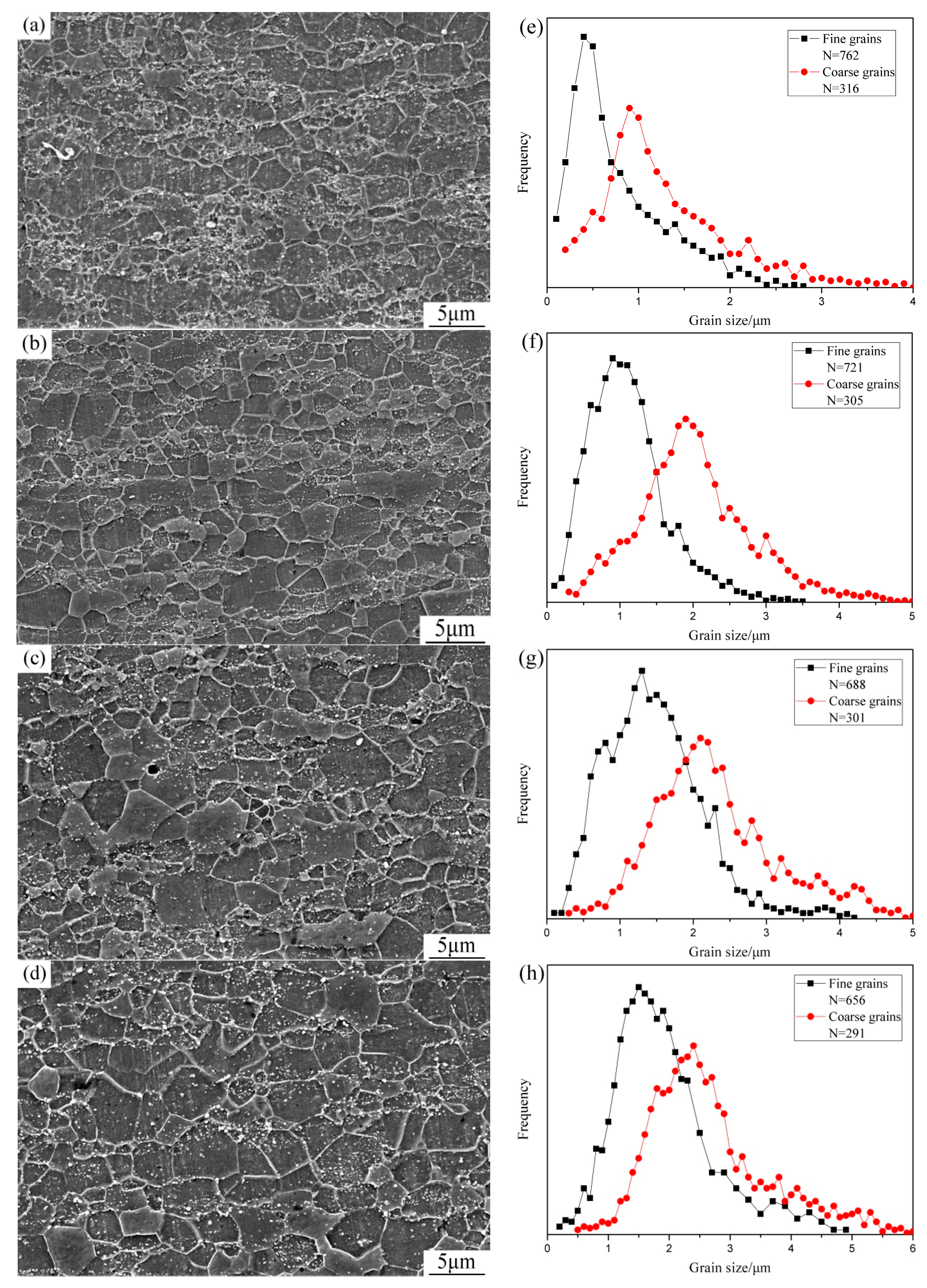
The cold-rolled microstructure of the dual-phase steel was shown in Figure 1b. It can be seen that the microstructure was fibroid along the rolling direction, and both martensite and ferrite were seriously distorted due to the large deformation. The microstructures of samples annealed at 650 °C for different holding times and the corresponding diagrams of grain size distribution were shown in Figure 2. The grain size measured was that of ferrite. Grains of the coarse grain region and fine grain region were counted separately. The fine grain region was formed by the recrystallization of originally deformed martensite and there were many fine carbides distributed in the fine grain region. However, there was no carbide precipitation in the coarse grain zone. In addition, the micro-hardness of the fine grain region was higher than that of the coarse grain region. Therefore, the annealed microstructures were marked first with a micro-Vickers durometer. To make the statistical results more accurate, three metallographic specimens were prepared for each annealed microstructure and three SEM images were taken from different locations on each metallographic specimen. When the annealing time was 30 min, although preliminary development of the bimodal phenomenon can be seen, the coarse grain region and fine grain region were both fine and the difference between them was not obvious. Furthermore, the grains with diameter ≤200 nm occupied a large proportion of the fine grain region, as shown in Figure 2a,e. When the annealing time was increased to 40 min, the bimodal characteristic was most obvious (Figure 2b). The peak value of the fine grain region was 0.91 μm and the peak value of the coarse grain region was 1.9 μm (Figure 2f). When the annealing time was 50 min, the change of grain size in the coarse grain region was not distinct. However, the grains with diameter ≥1.5 μm increased significantly in the fine grain region (Figure 2g). With the annealing time further increased, the bimodal characteristic gradually weakened (Figure 2d). The difference in grain size between the coarse and fine grain regions gradually reduced and the grain size gradually tended to become uniform, as shown in Figure 2h.
The martensite lath structure was preferentially destroyed via the large deformation during the cold rolling process. Hence, the large number of defects and the distortional energy present in the cold-rolled martensite can increase the nucleation rate of recrystallization and effectively refine the annealed microstructure [21,22]. Meanwhile, ferrite carried a much higher plastic deformation as it is softer than martensite. Thus, a large amount of distortional energy was stored in ferrite, which was also beneficial for the recrystallization of the cold-rolled microstructure and favorable for refining the annealed microstructure [7,8,9]. As shown in Figure 2a, when the annealing time was 30 min, the grains of the original ferrite region almost completed recrystallization. However, there were still incompletely recrystallized grains in the original martensite region. As shown in the white ellipse region of Figure 2a, the original martensite region was still fuzzy and remained slightly distorted. In addition, the Vickers hardness values of microstructures annealed for different times are shown in Figure 4. The microstructure annealed for 30 min retained a higher value of hardness than the subsequent annealing processes. This implied that the recrystallization of grains was not complete when annealed for 30 min. At the beginning of the annealing process, the main driving force (E) for recrystallization comes from the distortional energy [21,23]. Most of the deformation was carried out in the ferrite region due to its soft matrix during the cold rolling process. Hence, the distortional energy of unit volume stored in the martensite region (qm) was lower than that in the ferrite region (qf). In addition, there were many precipitates in the martensite region, as shown in Figure 3 (discussed below), which resulted in the restraining force in grain boundary migration. Therefore, the recrystallization of some deformed grains and the growth of some recrystallized grains in favorable positions were both blocked. Thus, the martensite region was gradually transformed to a fine grain region. However, the resistance of grain growth in the primary ferrite region was feeble and the stored distortion energy was higher, so these grains grew quickly and transformed to the coarse grain region.
The microstructure annealed at 650 °C for 40 min is shown in Figure 2b. It can be seen that all grains grew further and recrystallization was completed; grain boundaries in the coarse grains region and fine grains region were both clear. Meanwhile, the regions of fine grains and coarse grains were distributed in strips and formed a lamellar interphase structure, which is consistent with the distribution of cold-rolled martensite and ferrite. Besides, the percentage of fine grain and coarse grain regions were close to those of the original martensite and ferrite regions, respectively. At this condition, the bimodal characteristic of grain distribution was most obvious. When the annealing time was further increased to 50 min and 70 min, the grains of the fine grain region and coarse grain region both grew rapidly due to the more driving force. The Vickers hardness values of these microstructures were low, as shown in Figure 4. Meanwhile, the bimodal characteristics were increasingly obscured as shown in Figure 2c,g and Figure 2d,h. As mentioned earlier, the driving force for recrystallization in the original martensite region (Em) was lower than that in the original ferrite region (Ef) at the beginning of the annealing process, and the rate of increase Rf was greater than Rm. However, with the increase of annealing time, the deformed grains were gradually replaced with newly undistorted equiaxed grains. Therefore, qf and qm decreased gradually and eventually disappeared. When the rate of grain growth in the fine grain region was equal to the rate of grain growth in the coarse grain region, the difference in grain size was the largest and the bimodal characteristic of grain size distribution was most apparent, as shown in Figure 2b,f. The main driving force (E) for grain growth after complete recrystallization is the reduction of grain surface energy. The smaller the grain size is, the higher the surface energy is [24]. The assumption is that all grains are spherical. If R is the grain diameter, let γ be the surface energy per unit surface area of grains. Therefore the driving force for grain growth per unit volume in the martensite region (Em) and the ferrite region (Ef) are simplified as follows [24].
where k is the surface energy coefficient. When the annealing time increased further, Em > Ef, the rate of grain growth in the fine grain region exceeded that in the coarse grain region, so the grain sizes of the two regions were gradually consistent.
In addition, the grain growth was also affected by the drag of the second phase particle. The dispersed precipitates in the fine grain region (annealing for 40 min) are shown in Figure 3. A large number of white spots were distributed in the fine-grained region, which presented two kinds of morphology—rectangular and circular—at high magnification. The size of these precipitates was ~50 nm. The analysis results of EDS indicated that these precipitates contained large quantities of elements Cr, Mn, and Mo, as shown in Table 1. During heating of the two-phase region, most of the alloying elements dissolved in austenite due to their high solubilities. And in the subsequent quenching process, it was difficult for most of the alloying elements to diffuse due to the fast cooling rate. After quenching, a large number quantity of alloy elements (Cr and Mo) and carbon were supersaturated in α-Fe. After cold rolling, the martensite lath structure was preferentially destroyed via the large deformation during the cold rolling process and the large number of defects and the distortional energy present in the cold-rolled martensite. Therefore, during the subsequent annealing process, distorted martensite spontaneously recrystallized and the supersaturated carbon and alloy elements precipitated in the form of carbides dispersed in fine grain. Bimodal structure ultrafine-grained ferrite with nano-scale carbides was finally obtained.
3.2. Mechanical Properties of the Annealed Microstructures
The mechanical properties of the cold-rolled samples annealed at 650 °C and different holding times are shown in Figure 4. The yield strength increased first and then decreased slightly with the increase of annealing time, and the elongation increased always. Meanwhile, the yield strength and the elongation of all annealed samples improved relative to the dual-phase steel. Particularly, when the cold-rolled samples were annealed at 650 °C for 40 min, the yield strength (517 MPa) of the bimodal microstructure significantly improved, while the total elongation remained at a high level of 26%, which were attributed to the coordinated action of fine-grained strengthening, back-stress strengthening, and precipitation strengthening [16]. On the one hand, the refinement of bimodal ferrite grains and the increase of dislocation density with tensile strain caused an increase in stress, i.e., fine-grained strengthening, which was caused by the increase in grain boundaries [6,25,26]. On the other hand, the soft lamellae of coarse grains start plastic deformation first during the tensile process. However, they were constrained by the surrounding hard lamellae of the fine grains. Therefore, dislocations in coarse grains were piled up and blocked at lamella interfaces, which were actually grain boundaries. This produced a long-range back stress to increase the difficulty for dislocations to slip in the lamellae of coarse grains until the surrounding lamellae of fine grains started to yield at a larger global strain and to stop the dislocation source from emitting more dislocations [16,27,28]. This means that the soft lamellae constrained by hard lamellae appeared much stronger than when they were not constrained. Besides, there was a large amount of precipitation dispersed in the fine grain region of the bimodal ferrite microstructure, which would induce significant pinning effect on the dislocation motion in tension, i.e., precipitation strengthening [29,30]. In summary, the combined effect of fine-grained strengthening, back-stress strengthening, and precipitation strengthening gave the bimodal ferrite steel reasonable strength, although the microstructure of the bimodal ferrite steel was completely ferrite. Meanwhile, the complete ferrite matrix contributed to prominent elongation.
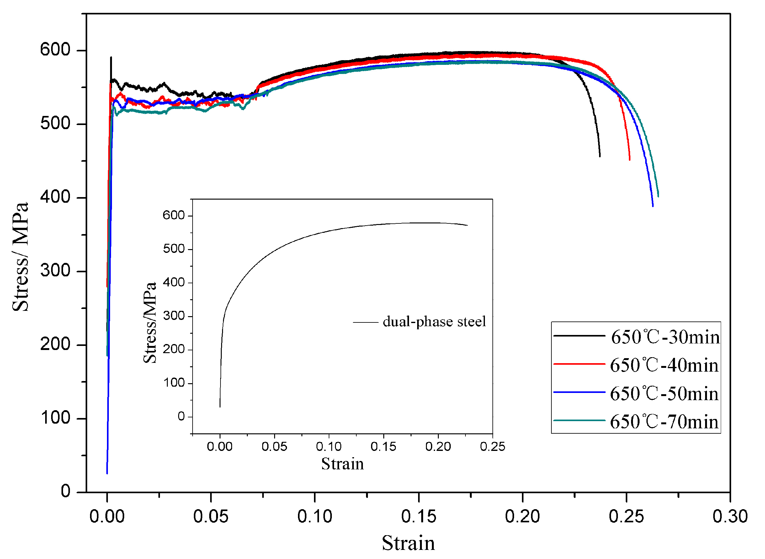
The stress-strain curves of the annealed specimens were also obtained during the tensile process as shown in Figure 5. Yield plateaus appeared in stress-strain curves of the annealed microstructures. Previous studies showed that the occurrence of a yield point needs to satisfy three conditions [31,32]: (i) low initially mobile dislocation density; (ii) rapid increase of dislocation during deformation; and (iii) rate of dislocation slip controlled by the loading stress. The annealed microstructures contained ultrafine-grained ferrite and nanoscale carbides; the recrystallization of ferrite was relatively completed, which caused the great disappearance of matrix dislocation. Because of the pinning effect of the Cottrell atmosphere [33] and precipitates [29,30] on dislocation, the motion of dislocation needed sufficient stress. Once the dislocation was free from pinning, it could move under relatively low stress. Therefore, the continuous appearance of this situation produced a yield platform. Besides, the decrease of grain size was beneficial for producing the yield platform and increasing the extension length of the yield platform [9,34]. Hence, the appearance of the yield plateau in bimodal ferrite steel was mainly due to ultrafine grains of ferrite and numerous nano-scale carbides.
3.3. Corrosion Behavior of Bimodal Ferrite Steel and Dual-Phase Steel
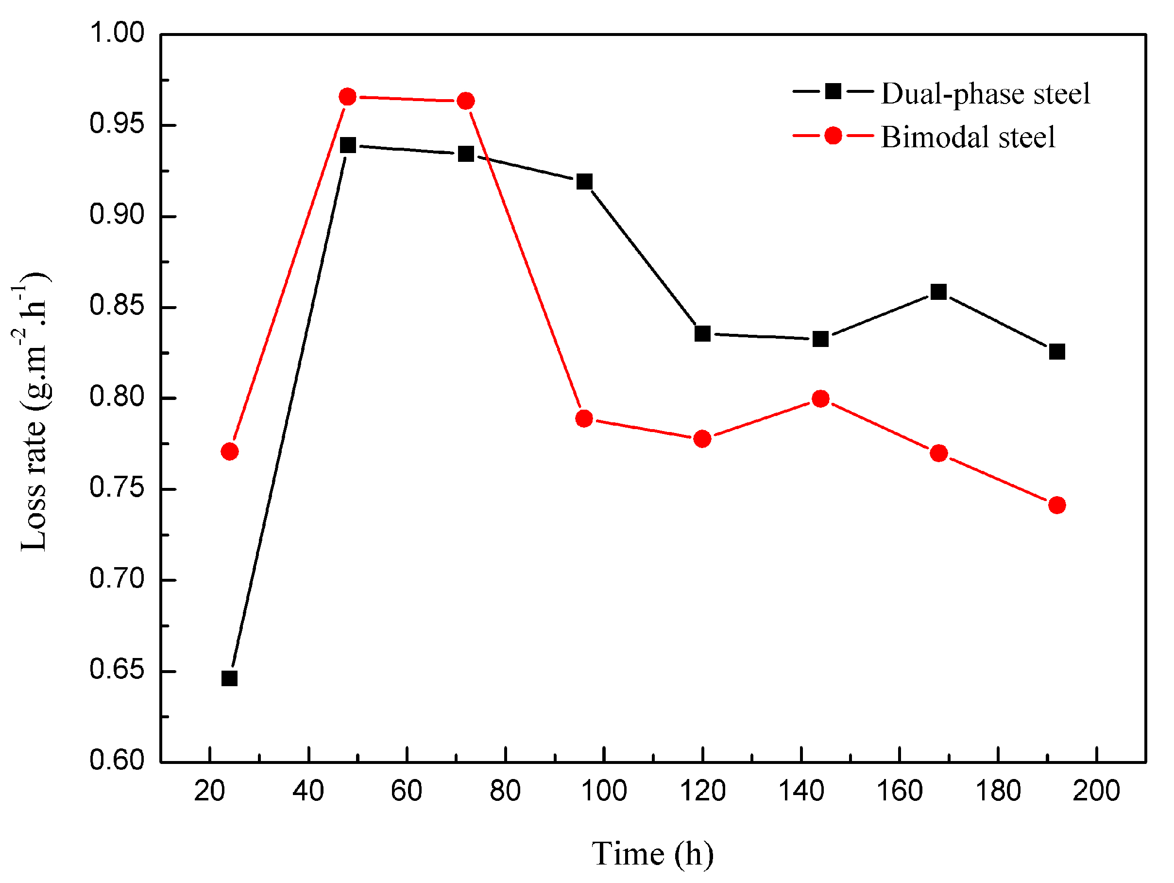
In order to study the corrosion behaviors of bimodal ferrite steel and dual-phase steel, the neutral salt spray, immersion, SKPFM, and electrochemistry tests were used. After neutral salt spray testing for eight days, the rates of weight loss for the two experimental steels are shown in Figure 6. The corrosion rates of both steels increased rapidly at the beginning of corrosion and then remained at a stable level. This is mainly because rust layers were not formed in the early stages and the corrosion resistances of the substrates were poor. In addition, the corrosion rate of bimodal ferrite steel was slightly higher than that of dual-phase steel. It is possible that a micro battery formed between the nanoscale precipitates and substrate, which was likely to promote corrosion. With the increase of corrosion time, a rust layer began to form. The dense and protective rust layer could form easier in the bimodal ferrite steel than in dual-phase steel. This was mostly because a large number of defects existed in martensite, which facilitated the occurrence and development of corrosion [5,6]. Meanwhile, the Figure 7b shows that the Volta potential of martensite was higher than the Volta potential of the surrounding ferrite and that the Volta potential difference between martensite and ferrite was large, which improved the electrochemical activity of the dual-phase microstructure and accelerated the progress of corrosion [19,20]. However, Figure 7a shows that the Volta potential of bimodal ferrite was low and there was no obvious Volta potential difference in bimodal ferrite. It is more difficult to form a dense and protective rust layer on the dual-phase microstructure than the bimodal microstructure. Therefore, when the corrosion time exceeded 72 h, the decrease of corrosion rate in the bimodal ferrite steel was faster due to the massive formation of compacted rust layers that can effectively hinder the permeation of the corrosion medium.
After immersion testing for seven days, the corrosion morphologies of the samples after removing corrosion product are shown in Figure 8. Figure 8a,b show that the corrosion of the two experimental steels were non-uniform, with pitting areas and full corrosion areas. Figure 8c,d show enlargement of the full corrosion area in both steels. Figure 8e,f shows enlargement of the pitting area in both steels. It can be seen that corrosion of dual-phase steel was more serious, and the corrosion depth of dual-phase steel was larger than that of bimodal ferrite steel. As mentioned earlier, there were several defects in the martensite substrate, which accelerated the corrosion of samples, facilitated the extension of corrosion pits in the substrate. And were not conducive to the formation of a compact rust layer. The result of the SKPFM test also showed that the Volta potential difference between martensite and ferrite was large, as shown in Figure 7b. However, Figure 7a implies that the Volta potentials of very few regions were high in bimodal ferrite steel. There was probably a micro battery between the nanoscale precipitates and substrate in the fine grain region.
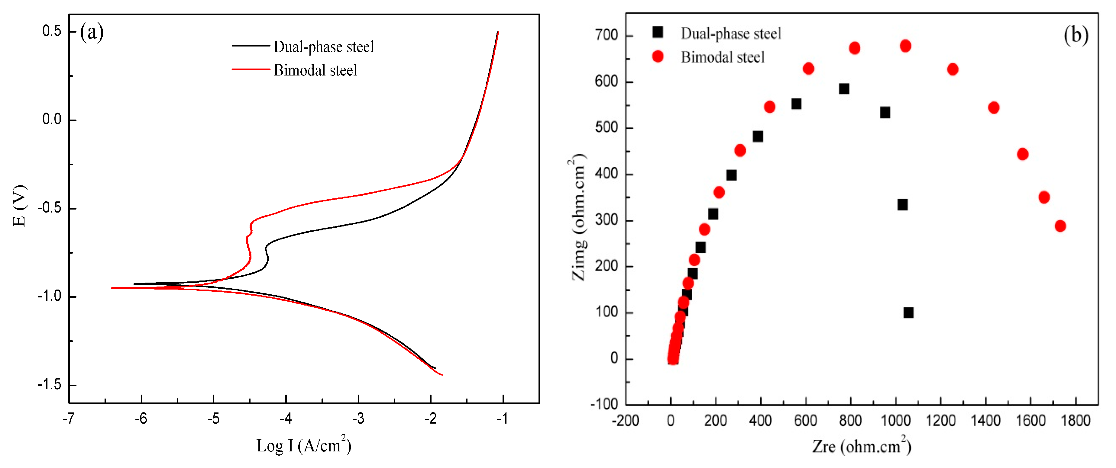
The results of the electrochemistry test are shown in Figure 9. Figure 9a shows that passivation regions were observed in both steels. When the samples were placed in the electrolyte, ion exchange between the sample surface and the solution gradually formed a dynamic balance. When voltage was applied, this dynamic balance was quickly destroyed and the electrode potential increased rapidly, leading to the increase of current density and accelerated the corrosion. However, with the increase in corrosion time, the sample surface was gradually passivated. The electrode potential continued to increase but the current was nearly constant at this stage. This current is known as the passivation current which can be used to characterize the corrosion resistances of metals. The smaller the passivation current is, the better the corrosion resistance is [35]. Hence, the corrosion resistance of bimodal ferrite steel was better than that of dual-phase steel, as shown in Figure 9a. With the further increase of potential, the current increased instantaneously. Here, voltage corresponded to the breakdown voltage of the passivation film, which can be used to characterize the stability of the passivation film. The higher the breakdown potential is, the better the stability of passivation film is [36]. Therefore, the stability of the passivation film in bimodal ferrite steel was better than that of dual-phase steel, as shown in Figure 9a. The electrochemical impedance spectrum (EIS, shown in Figure 9b) results showed that the radius of EIS in the bimodal ferrite steel was larger than that of dual-phase steel. The higher the radius of EIS, the stronger the stability of the passivation film [37,38,39]. Therefore, the enhancement of corrosion resistance of the bimodal structure ultrafine-grained ferrite steel was mainly achieved by promoting the formation of a dense rust layer and strengthening the stability of the rust layer.
4. Conclusions
- With the annealing time increasing, deformed ferrite and deformed martensite gradually recrystallized. When the samples were annealed at 650 °C for 40 min, a bimodal microstructure was obtained and the fine grain region and coarse grain region were distributed in bands. The peak value of the fine grain region was 0.91 μm, the peak value of coarse grain region was 1.9 μm.
- Bimodal structured ultrafine-grained ferrite steel had better comprehensive mechanical properties than dual-phase steel. This is mainly because the hard fine grains were embedded in the soft coarse grains to form a lamellar interphase structure. The fine-grained strengthening, back-stress strengthening, and precipitation strengthening produced by the lamellar interphase structure contributed to the excellent match of strength and ductility. Meanwhile, complete ferrite with ultrafine grains was conducive to the appearance of the yield plateau.
- The neutral salt spray, immersion, SKPFM, and the electrochemistry tests showed that the corrosion resistance of bimodal ferrite steel was better than that of dual-phase steel. The main reason was there were several defects in the martensite substrate and the potential difference between martensite and ferrite was large, which accelerated the corrosion process and was not conducive to the formation of a compact rust layer. On the contrary, the substrate of bimodal ferrite microstructure contained fewer defects and there was no obvious potential difference, which was detrimental to the occurrence and development of corrosion and conducive to forming a protective rust layer. Therefore, the bimodal structured ultrafine-grained ferrite steel possessed excellent corrosion resistance.
Acknowledgments
This research was supported by the National Natural Science Foundation of China (Grant No. 51474031).
Author Contributions
Gang Niu, Huibin Wu and Di Tang conceived and designed the experiments; Gang Niu and Da Zhang performed the experiments; Gang Niu, Huibin Wu, and Na Gong analyzed the data; Da Zhang contributed reagents/materials/analysis tools; Gang Niu wrote the paper; Huibin Wu revised the language in this paper.
Conflicts of Interest
The authors declare no conflict of interest.
References
- Ghosh, S.; Singh, A.K.; Mula, S.; Chanda, P.; Mahashabde, V.V.; Roy, T.K. Mechanical properties, formability and corrosion resistance of thermomechanically controlled processed Ti-Nb stabilized IF steel. Mater. Sci. Eng. A 2017, 684, 22–36. [Google Scholar] [CrossRef]
- Qu, S.; Pang, X.; Wang, Y.; Gao, K. Corrosion behavior of each phase in low carbon microalloyed ferrite-bainite dual-phase steel: Experiments and modeling. Corros. Sci. 2013, 75, 67–77. [Google Scholar] [CrossRef]
- Wu, H.; Liang, J.; Tang, D.; Liu, X.; Zhang, P.; Yue, Y. Influence of Inclusion on Corrosion Behavior of E36 Grade Low-alloy Steel in Cargo Oil Tank Bottom Plate Environment. J. Iron Steel Res. Int. 2014, 21, 1016–1021. [Google Scholar] [CrossRef]
- Al-Duheisat, S.A.; El-Amoush, A.S. Effect of deformation conditions on the corrosion behavior of the low alloy structural steel girders. Mater. Des. 2016, 89, 342–347. [Google Scholar] [CrossRef]
- Osório, W.R.; Peixoto, L.C.; Garcia, A. Electrochemical corrosion behaviour of a Ti-IF steel and a SAE 1020 steel in a 0.5 M NaCl solution. Mater. Corros. 2010, 61, 407–411. [Google Scholar] [CrossRef]
- Zeng, Y.; Jiang, B.; Li, R.; Yin, H.; Al-Ezzi, S. Grain Refinement Mechanism of the As-Cast and As-Extruded Mg–14Li Alloys with Al or Sn Addition. Metals 2017, 7, 172. [Google Scholar] [CrossRef]
- Zhao, D.; Liu, Y.; Liu, F.; Wen, Y.; Zhang, L.; Dou, Y. ODS ferritic steel engineered with bimodal grain size for high strength and ductility. Mater. Lett. 2011, 65, 1672–1674. [Google Scholar]
- Odnobokova, M.; Belyakov, A.; Kaibyshev, R. Development of nanocrystalline 304L stainless steel by large strain cold working. Metals 2015, 5, 656–668. [Google Scholar] [CrossRef]
- Zhao, M.; Yin, F.; Hanamura, T.; Nagai, K.; Atrens, A. Relationship between yield strength and grain size for a bimodal structural ultrafine-grained ferrite/cementite steel. Scr. Mater. 2007, 57, 857–860. [Google Scholar] [CrossRef]
- Yuan, W.; Panigrahi, S.K.; Su, J.Q.; Mishra, R.S. Influence of grain size and texture on Hall–Petch relationship for a magnesium alloy. Scr. Mater. 2011, 65, 994–997. [Google Scholar] [CrossRef]
- Wei, Y.; Li, Y.; Zhu, L.; Liu, Y.; Lei, X.; Wang, G.; Gao, H. Evading the strength-ductility trade-off dilemma in steel through gradient hierarchical nanotwins. Nat. Commun. 2014, 5, 3580. [Google Scholar] [CrossRef] [PubMed]
- Wu, X.; Yuan, F.; Yang, M.; Jiang, P.; Zhang, C.; Chen, L.; Ma, E. Nanodomained nickel unite nanocrystal strength with coarse-grain ductility. Sci. Rep. 2015, 5, 11728. [Google Scholar] [CrossRef] [PubMed]
- Ueno, H.; Kakihata, K.; Kaneko, Y.; Hashimoto, S.; Vinogradov, A. Nanostructurization assisted by twinning during equal channel angular pressing of metastable 316L stainless steel. J. Mater. Sci. 2011, 46, 4276–4283. [Google Scholar] [CrossRef]
- Wu, H.; Niu, G.; Wu, F.; Tang, D. Reverse-transformation austenite structure control with micro/nanometer size. Int. J. Miner. Metall. Mater. 2017, 24, 530–537. [Google Scholar] [CrossRef]
- Karmakar, A.; Karani, A.; Patra, S.; Chakrabarti, D. Development of bimodal ferrite-grain structures in low-carbon steel using rapid intercritical annealing. Metall. Mater. Trans. A 2013, 44, 2041–2052. [Google Scholar] [CrossRef]
- Wu, X.; Yang, M.; Yuan, F.; Wu, G.; Wei, Y.; Huang, X.; Zhu, Y. Heterogeneous lamella structure unites ultrafine-grain strength with coarse-grain ductility. Proc. Natl. Acad. Sci. USA 2015, 112, 14501–14505. [Google Scholar] [CrossRef] [PubMed]
- Vajpai, S.K.; Ota, M.; Zhang, Z.; Ameyama, K. Three-dimensionally gradient harmonic structure design: An integrated approach for high performance structural materials. Mater. Res. Lett. 2016, 4, 191–197. [Google Scholar] [CrossRef]
- Tan, H.; Jiang, Y.; Deng, B.; Sun, T.; Xu, J.; Li, J. Effect of annealing temperature on the pitting corrosion resistance of super duplex stainless steel UNS S32750. Mater. Charact. 2009, 60, 1049–1054. [Google Scholar] [CrossRef]
- Örnek, C.; Engelberg, D.L. SKPFM measured Volta potential correlated with strain localisation in microstructure to understand corrosion susceptibility of cold-rolled grade 2205 duplex stainless steel. Corros. Sci. 2015, 99, 164–171. [Google Scholar] [CrossRef]
- Nakhaie, D.; Davoodi, A.; Imani, A. The role of constituent phases on corrosion initiation of NiAl bronze in acidic media studied by SEM-EDS, AFM and SKPFM. Corros. Sci. 2014, 80, 104–110. [Google Scholar] [CrossRef]
- Kisko, A.; Hamada, A.S.; Talonen, J.; Porter, D.; Karjalainen, L.P. Effects of reversion and recrystallization on microstructure and mechanical properties of Nb-alloyed low-Ni high-Mn austenitic stainless steels. Mater. Sci. Eng. A 2016, 657, 359–370. [Google Scholar] [CrossRef]
- Wu, H.; Niu, G.; Cao, J.; Yang, M. Annealing of strain-induced martensite to obtain micro/nanometre grains in austenitic stainless. Mater. Sci. Technol. 2017, 33, 480–486. [Google Scholar] [CrossRef]
- Meng, Y.; Sugiyama, S.; Yanagimoto, J. Microstructural evolution during RAP process and deformation behavior of semi-solid SKD61 tool steel. J. Mater. Process. Technol. 2012, 212, 1731–1741. [Google Scholar] [CrossRef]
- Li, W.; Wu, Y.; He, J.; Nieh, T.; Lu, Z. Grain growth and the Hall–Petch relationship in a high-entropy FeCrNiCoMn alloy. Scr. Mater. 2013, 68, 526–529. [Google Scholar] [CrossRef]
- Gutierrez-Urrutia, I.; Zaefferer, S.; Raabe, D. The effect of grain size and grain orientation on deformation twinning in a Fe–22 wt. % Mn–0.6 wt. % C TWIP steel. Mater. Sci. Eng. A 2010, 527, 3552–3560. [Google Scholar] [CrossRef]
- Thijs, L.; Sistiaga, M.L.M.; Wauthle, R.; Xie, Q.; Kruth, J.P.; Van Humbeeck, J. Strong morphological and crystallographic texture and resulting yield strength anisotropy in selective laser melted tantalum. Acta Mater. 2013, 61, 4657–4668. [Google Scholar] [CrossRef]
- Sinclair, C.; Saada, G.; Embury, J. Role of internal stresses in co-deformed two-phase materials. Philos. Mag. 2006, 86, 4081–4098. [Google Scholar] [CrossRef]
- Mughrabi, H. Dislocation wall and cell structures and long-range internal stresses in deformed metal crystals. Acta Metall. 1983, 31, 1367–1379. [Google Scholar] [CrossRef]
- Funakawa, Y.; Shiozaki, T.; Tomita, K.; Yamamoto, T.; Maeda, E. Development of high strength hot-rolled sheet steel consisting of ferrite and nanometer-sized carbides. ISIJ Int. 2004, 44, 1945–1951. [Google Scholar] [CrossRef]
- Kapoor, M.; Isheim, D.; Ghosh, G.; Vaynman, S.; Fine, M.E.; Chung, Y.W. Aging characteristics and mechanical properties of 1600 MPa body-centered cubic Cu and B2-NiAl precipitation-strengthened ferritic steel. Acta Mater. 2014, 73, 56–74. [Google Scholar] [CrossRef]
- Kumar, A.; Singh, S.B.; Ray, K.K. Influence of bainite/martensite-content on the tensile properties of low carbon dual-phase steels. Mater. Sci. Eng. A 2008, 474, 270–282. [Google Scholar] [CrossRef]
- Ucak, A.; Tsopelas, P. Constitutive model for cyclic response of structural steels with yield plateau. J. Struct. Eng. 2010, 137, 195–206. [Google Scholar] [CrossRef]
- Cottrell, A.H.; Bilby, B.A. Dislocation theory of yielding and strain ageing of iron. Proc. Phys. Soc. Sect. A 1949, 62, 49. [Google Scholar] [CrossRef]
- Schulson, E.M.; Weihs, T.P.; Viens, D.V.; Baker, I. The effect of grain size on the yield strength of Ni3Al. Acta Metall. 1985, 33, 1587–1591. [Google Scholar] [CrossRef]
- Balyanov, A.; Kutnyakova, J.; Amirkhanova, N.A.; Stolyarov, V.V.; Valiev, R.Z.; Liao, X.Z.; Zhu, Y.T. Corrosion resistance of ultrafine-grained Ti. Scr. Mater. 2004, 51, 225–229. [Google Scholar] [CrossRef]
- Gurappa, I. Characterization of different materials for corrosion resistance under simulated body fluid conditions. Mater. Charact. 2002, 49, 73–79. [Google Scholar] [CrossRef]
- Liu, C.; Bi, Q.; Leyland, A.; Matthews, A. An electrochemical impedance spectroscopy study of the corrosion behaviour of PVD coated steels in 0.5 N NaCl aqueous solution: Part II.: EIS interpretation of corrosion behavior. Corros. Sci. 2003, 45, 1257–1273. [Google Scholar] [CrossRef]
- Hoseinpoor, M.; Momeni, M.; Moayed, M.H.; Davoodi, A. EIS assessment of critical pitting temperature of 2205 duplex stainless steel in acidified ferric chloride solution. Corros. Sci. 2014, 80, 197–204. [Google Scholar] [CrossRef]
- Ghaffari, M.; Saeb, M.R.; Ramezanzadeh, B.; Taheri, P. Demonstration of epoxy/carbon steel interfacial delamination behavior: Electrochemical impedance and X-ray spectroscopic analyses. Corros. Sci. 2016, 102, 326–337. [Google Scholar] [CrossRef]
Figure 1.
Microstructures of dual-phase steel (a) before cold rolling and (b) after cold rolling.
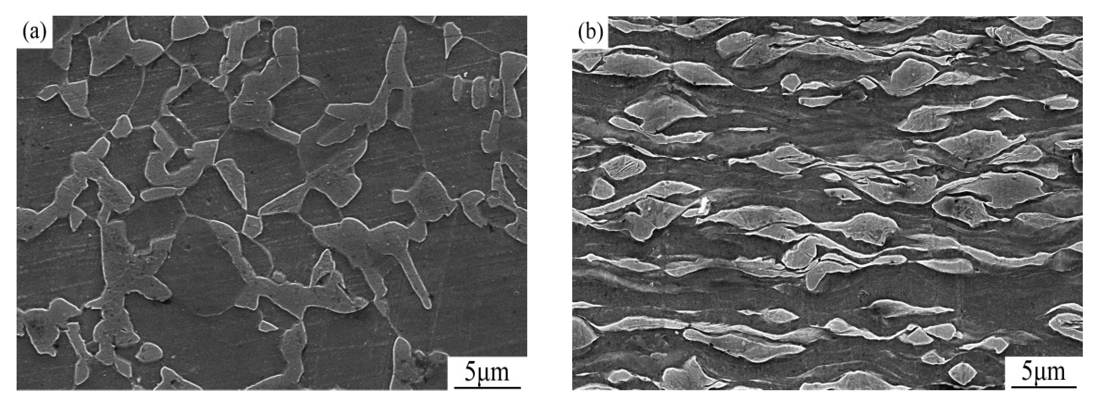
Figure 2.
The annealed microstructures at 650 °C and different holding times, and the corresponding diagrams of grain size distribution. Number of the measured grains (N) was given. (a,e) 30 min; (b,f) 40 min; (c,g) 50 min; (d,h) 70 min.
Figure 2.
The annealed microstructures at 650 °C and different holding times, and the corresponding diagrams of grain size distribution. Number of the measured grains (N) was given. (a,e) 30 min; (b,f) 40 min; (c,g) 50 min; (d,h) 70 min.

Figure 3.
TEM micrographs of precipitates in the fine grain region; (a) distribution of precipitates; (b) rectangular precipitate; (c) circular precipitate.
Figure 3.
TEM micrographs of precipitates in the fine grain region; (a) distribution of precipitates; (b) rectangular precipitate; (c) circular precipitate.
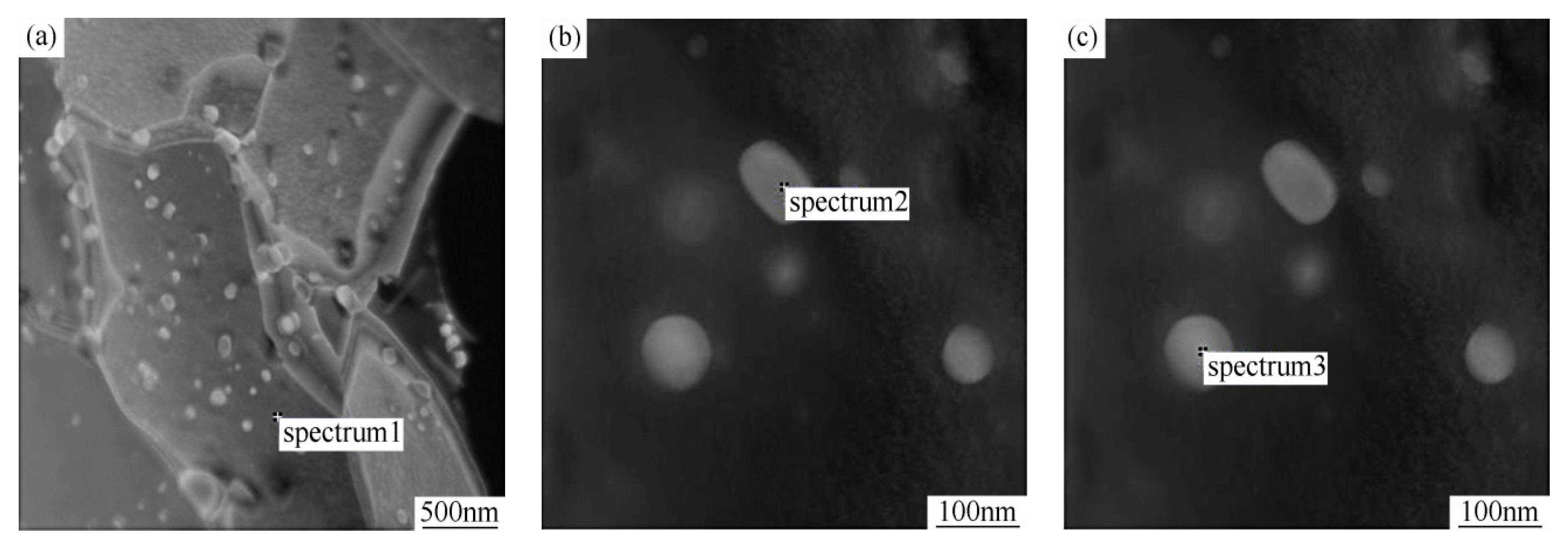
Figure 4.
Mechanical properties of cold-rolled specimens annealed at 650 °C and different holding times. The first value of yield strength, tensile strength, and elongation belongs to the dual-phase steel (the Vickers hardness of the dual-phase steel was 194 HV). The first value of Vickers hardness belongs to the dual-phase steel after cold rolling (The values of yield strength, tensile strength, and elongation of the dual-phase steel after cold rolling were 1008 MPa, 1125 MPa, and 4.7%, respectively).
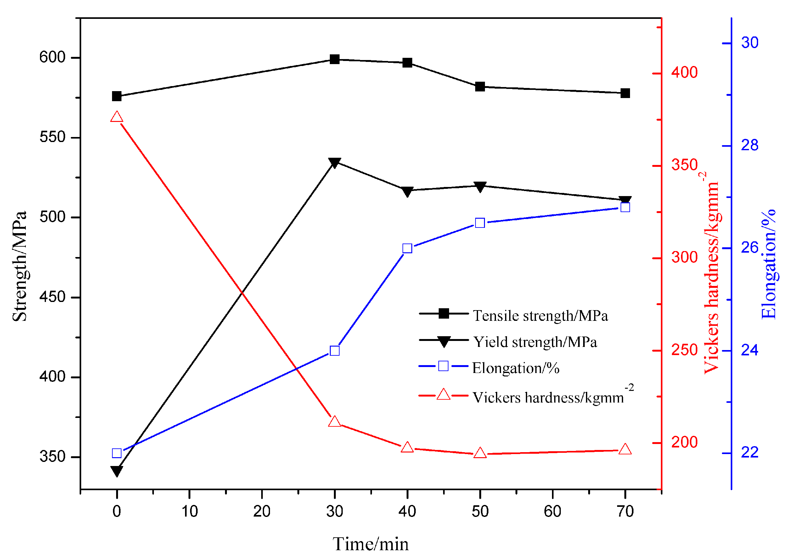
Figure 5.
Stress-strain curves of the original dual-phase steel and the specimens annealed at 650 °C for different holding times.
Figure 5.
Stress-strain curves of the original dual-phase steel and the specimens annealed at 650 °C for different holding times.

Figure 6.
The rate of weight loss for dual-phase steel and bimodal ferrite steel (annealed for 40 min).
Figure 6.
The rate of weight loss for dual-phase steel and bimodal ferrite steel (annealed for 40 min).

Figure 7.
Volta potential images of (a) bimodal ferrite steel and (b) dual-phase steel.
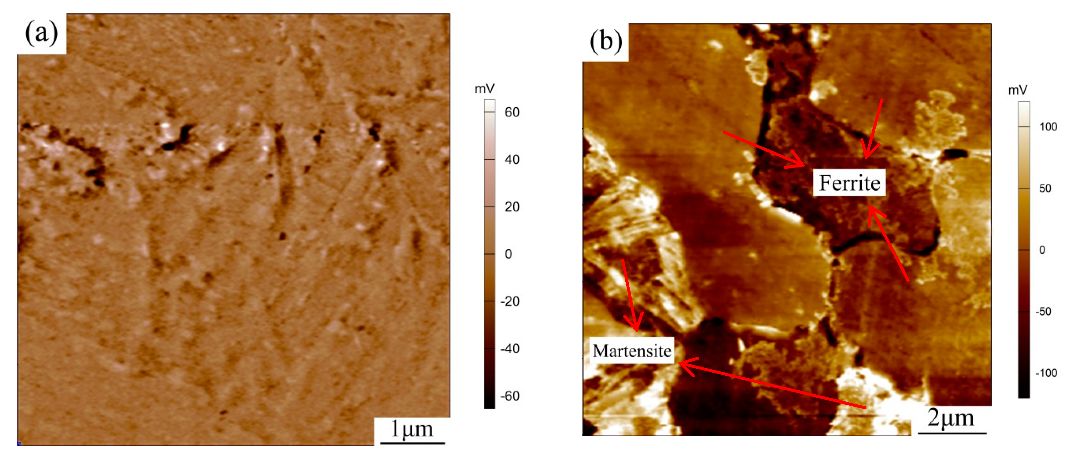
Figure 8.
The corrosion morphologies of samples with corrosion product removed (a,c,e)—bimodal ferrite steel; (b,d,f)—dual-phase steel.
Figure 8.
The corrosion morphologies of samples with corrosion product removed (a,c,e)—bimodal ferrite steel; (b,d,f)—dual-phase steel.
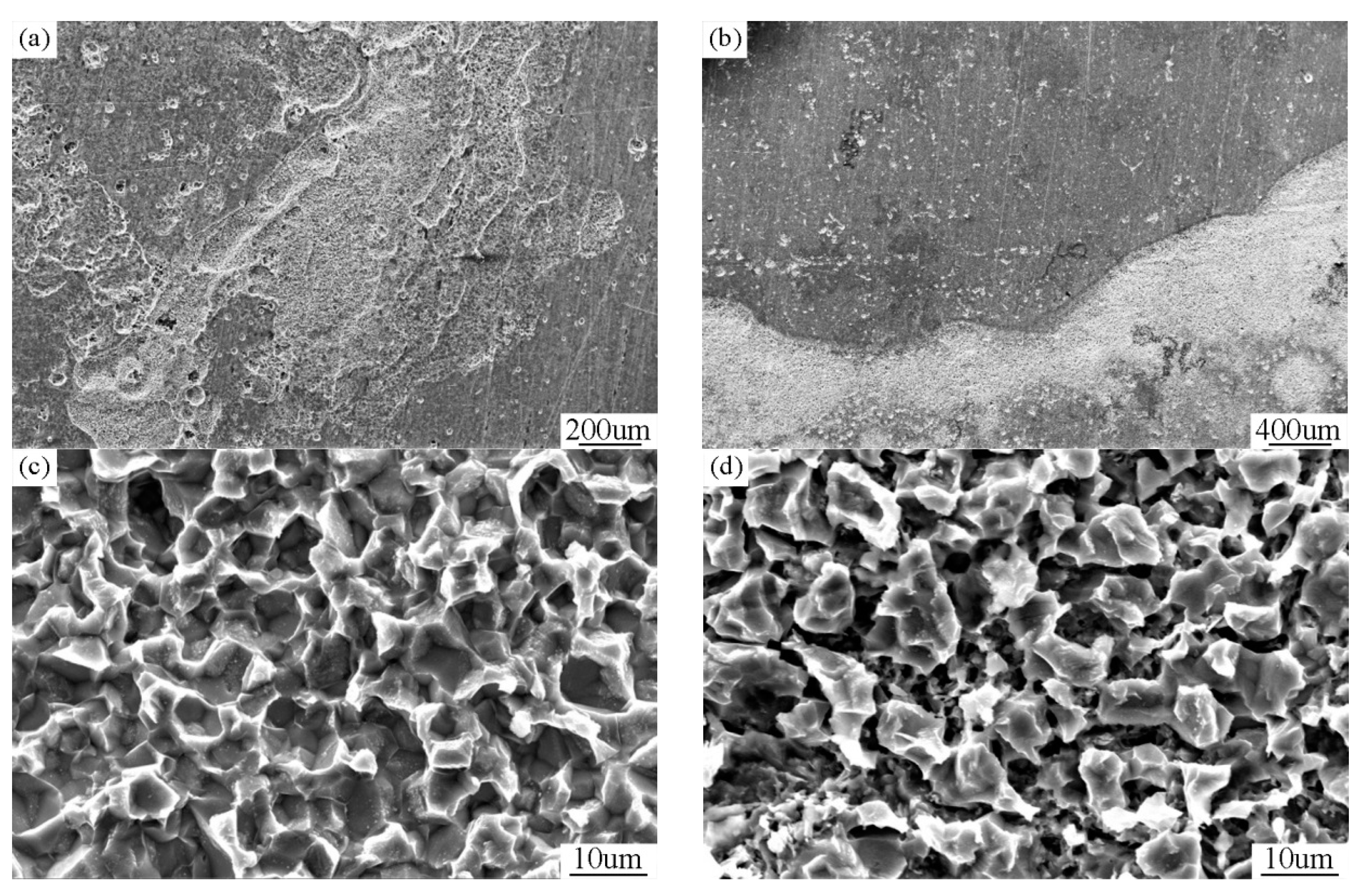
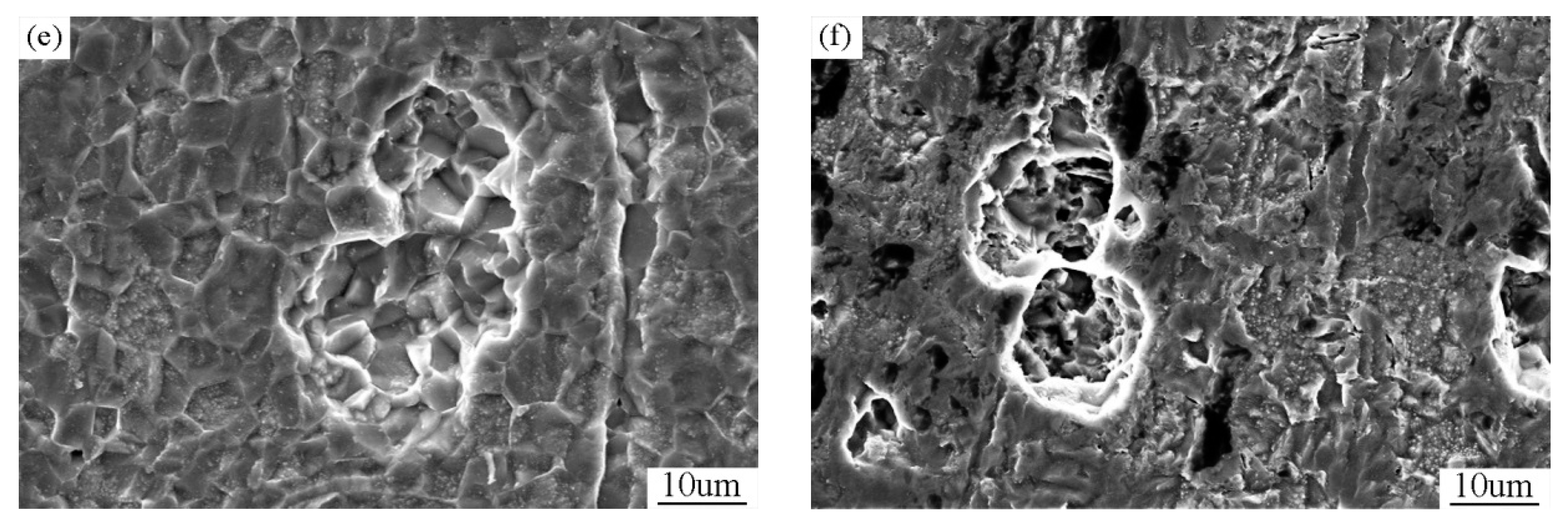
Figure 9.
The results of the electrochemistry test: (a) polarization curve and (b) AC impedance spectroscopy.
Figure 9.
The results of the electrochemistry test: (a) polarization curve and (b) AC impedance spectroscopy.

Table 1.
The results of EDS analysis of precipitates and matrix (wt %).
| Alloy Element | Spectrum1 (Matrix) | Spectrum2 (Precipitate) | Spectrum3 (Precipitate) |
|---|---|---|---|
| Si | 1.5 | 1.2 | 0.8 |
| Fe | 97.0 | 81.3 | 77.7 |
| Mn | 1.0 | 9.0 | 12.1 |
| Cr | 0.5 | 6.6 | 7.7 |
| Mo | - | 2.0 | 1.6 |
© 2017 by the authors. Licensee MDPI, Basel, Switzerland. This article is an open access article distributed under the terms and conditions of the Creative Commons Attribution (CC BY) license (http://creativecommons.org/licenses/by/4.0/).
Share and Cite
MDPI and ACS Style
Niu, G.; Wu, H.; Zhang, D.; Gong, N.; Tang, D. Study on Microstructure and Properties of Bimodal Structured Ultrafine-Grained Ferrite Steel. Metals 2017, 7, 316. https://doi.org/10.3390/met7080316
AMA Style
Niu G, Wu H, Zhang D, Gong N, Tang D. Study on Microstructure and Properties of Bimodal Structured Ultrafine-Grained Ferrite Steel. Metals. 2017; 7(8):316. https://doi.org/10.3390/met7080316
Chicago/Turabian StyleNiu, Gang, Huibin Wu, Da Zhang, Na Gong, and Di Tang. 2017. "Study on Microstructure and Properties of Bimodal Structured Ultrafine-Grained Ferrite Steel" Metals 7, no. 8: 316. https://doi.org/10.3390/met7080316
Note that from the first issue of 2016, this journal uses article numbers instead of page numbers. See further details here.