Article

The Formation and Evolution of Shear Bands in Plane Strain Compressed Nickel-Base Superalloy

1
State Key Laboratory of Solidification Processing, Northwestern Polytechnical University, Xi’an 710072, China
2
AVIC Beijing Aeronautical Manufacturing Technology Research Institute, Beijing 100024, China
*
Author to whom correspondence should be addressed.
Metals 2018, 8(2), 141; https://doi.org/10.3390/met8020141
Submission received: 22 January 2018 / Revised: 2 February 2018 / Accepted: 9 February 2018 / Published: 18 February 2018

Abstract

:
The formation and evolution of shear bands in Inconel 718 nickel-base superalloy under plane strain compression was investigated in the present work. It is found that the propagation of shear bands under plane strain compression is more intense in comparison with conventional uniaxial compression. The morphology of shear bands was identified to generally fall into two categories: in “S” shape at severe conditions (low temperatures and high strain rates) and “X” shape at mild conditions (high temperatures and low strain rates). However, uniform deformation at the mesoscale without shear bands was also obtained by compressing at 1050 °C/0.001 s−1. By using the finite element method (FEM), the formation mechanism of the shear bands in the present study was explored for the special deformation mode of plane strain compression. Furthermore, the effect of processing parameters, i.e., strain rate and temperature, on the morphology and evolution of shear bands was discussed following a phenomenological approach. The plane strain compression attempt in the present work yields important information for processing parameters optimization and failure prediction under plane strain loading conditions of the Inconel 718 superalloy.

1. Introduction

The precipitation-hardened Inconel 718 nickel-base superalloy has been widely used in the manufacturing of critical components in aircraft engines and land-based gas turbines, primarily due to the excellent mechanical properties at high temperatures as well as the extraordinary corrosion-oxidation resistance [1,2]. Due to the severe working conditions Inconel 718 alloys are usually subjected to, obtaining a defect-free part with appropriate microstructure is essential for reliability. Therefore, special attention must be paid to each step of the thermomechanical treatments. Hot-working operations are usually conducted above half the melting temperature for this alloy to achieve finished or semi-finished components with desired performance. However, the hot-working approach at high temperature usually results in complex localized deformation. In this case, the alloys will experience a softening process and the applied forming force is sensitive to processing parameters such as temperature and strain rate [3]. Recent studies show that the flow softening behavior is closely related to various special microstructure characteristics such as shear bands, the precipitation of second phase and strain localization [4,5,6], except for the well-known dynamic recrystallization (DRX) [7] and dynamic recovery (DRV) [8], wherein the propagation of shear band characterized by narrow bands is usually found during the high strain rate inelastic deformation process due to the intense shear straining. Once a shear band is initiated, it may become self-propagating because the intrinsic adiabatic heating produces a remarkable decrease of the local flow stress [9]. The shear band is a potentially dangerous factor for deformation and may result in localized deformation and local failure. It not only can significantly degrade the mechanical properties of alloys, but also can lead to the final failure of the component due to the shear-induced cracking. Therefore, a new insight of the flow characteristics at various deformation conditions during hot-working process is of great importance in controlling deformation, and contributing to obtain desirable components.
Up to now, many studies focused on the flow instability of alloys by means of isothermal uniaxial compression [10,11,12]. However, only few investigations primarily concerned with the flow behavior under the plane strain compression [13]. In the present study, the deformation behavior of Inconel 718 superalloy in generalized plane strain conditions subjected to pressure and elevated temperature is investigated and discussed. The effect of processing parameters on shear band propagation and unstable plastic was studied by analyzing the flow curves and microstructures. Furthermore, the finite element method (FEM) [14,15] was employed to interpret the occurrence and evolution of shear bands during the compression process. The present work for Inconel 718 superalloy yields important information for the optimizing of processing parameters and failure prediction under plane strain conditions.

2. Experimental Procedures

The hot deformation behavior of Inconel 718 superalloy was investigated by means of plane strain compression in the present work. The received material was in the form of sheet with thickness of 8 mm, and the chemical composition (wt. %) of the alloy is shown in Table 1. Figure 1 shows the initial microstructure of the received sheet. Note that the sheet has a typical equiaxial microstructure containing twins (noted by black arrows). In order to obtain a microstructure with single γ phase, the sheet was solution treated before the testing of compression. Subsequently, rectangular specimens with dimension of 15 mm × 10 mm × 8 mm were cut by electro-discharge machining from the sheet. The compression tests were performed on a thermomechanical simulator at a temperature range of 900 °C to 1050 °C and at strain rates from 0.001 s−1 to 10 s−1. Specimens were heat treated with a heating rate of 10 °C/s and held at testing temperature for 5 min prior to mechanical testing. The true stress–true strain curves were calculated from the obtained loading–displacement data. In order to evaluate the microstructure evolution at specific temperatures and strain rates during the deformation process, the specimens were air cooled immediately after being compressed to a strain of 0.8. The deformed specimens were sectioned along the length of themselves with a direction parallel to the compression axis. In order to characterize the morphologies of shear bands, the optical microscope (OM) was employed for the microstructure observations.

3. Results and Discussion
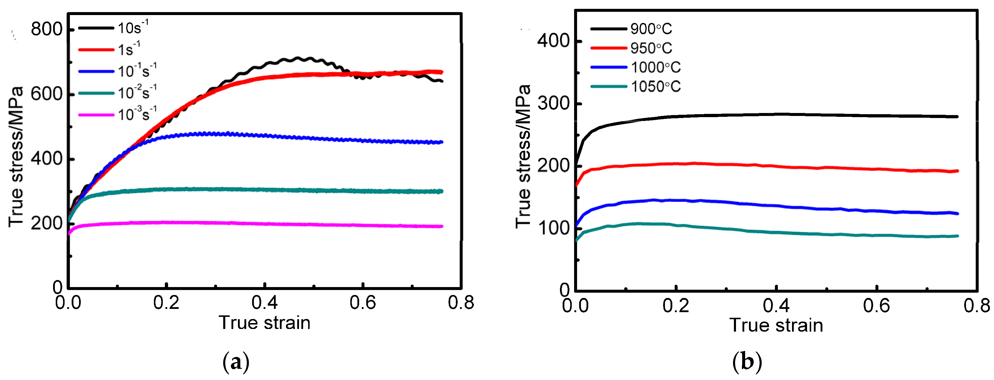
3.1. Flow Behavior

The measured true stress–true strain curves are presented in Figure 2. As shown in Figure 2, the flow stress is sensitive to the temperature and strain rate. When the alloy is deformed at 10 s−1, an abnormal softening phenomenon caused by adiabatic heating is observed. However, only slight softening can be detected at other conditions, even if the deformation was carried out under the lowest strain rate (10−3 s−1) and highest temperatures (1050 °C). It is well-known that DRX intensively occurs in the hot deformation process of Ni-based alloys, resulting in dynamic softening of the alloys and continuous decreasing of the flow strength. The slight softening of the alloy can be explained by the variation of the DRX mechanism [11,16,17,18]. At high strain rates or low deformation temperatures, discontinuous DRX (DDRX) occurs, resulting in obviously softening. Besides, the continuous DRX (CDRX) prefers to initiate and thus leads to slight softening, when deforming at low strain rate and high temperature conditions. For the flow curves, the synergic effect of the two DRX mechanisms reduces the corresponding flow stress from approximately 650 MPa at 10 s−1 to 200 MPa at 10−3 s−1 in Figure 2a. Similarly in Figure 2b the flow stresses reduces from 275 MPa at 900 °C to 100 MPa at 1050 °C.

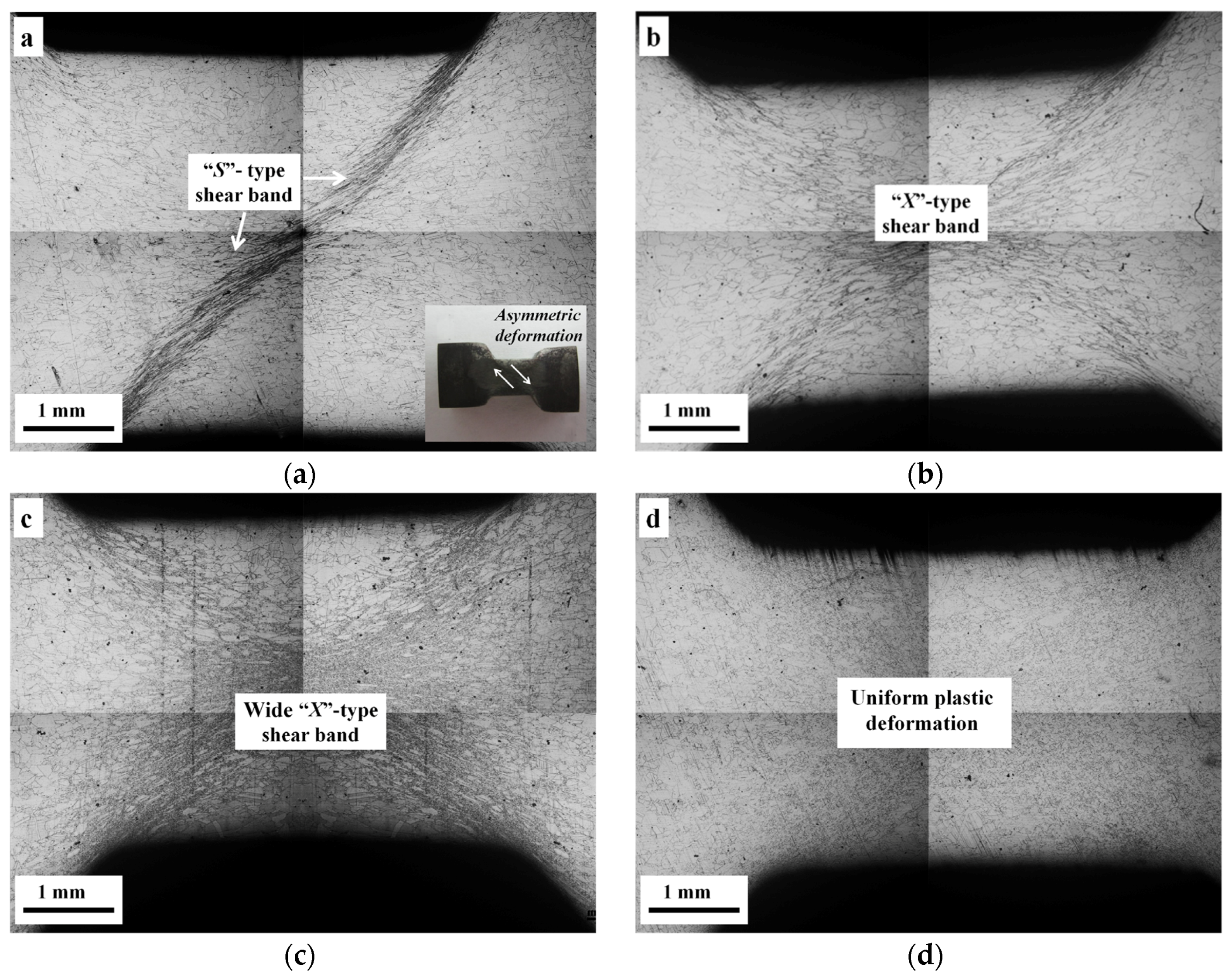
3.2. Characterization of Shear Bands

The etched microstructures of the specimens are shown in Figure 3, from which the shear bands and strain localization regions under different deformation conditions can be seen as dark-colored regions. It can be concluded that the shear bands exhibit approximate “S” shape which passes totally through the entire width of the sample under “severe” conditions (low temperatures and high strain rate, e.g., 900 °C/10 s−1 shown in Figure 3a). Note that the samples were asymmetrically deformed under these severe conditions. It must be confirmed that the parallelism of the Gleeble anvils and the samples was controlled below 0.01 mm. Therefore, the asymmetry of deformation cannot result from the deviation between contact surfaces and the compression axis. Note that the samples asymmetrically deformed under these severe conditions result from the intrinsic mechanism.
When the samples were compressed at “intermediate” conditions (high temperature or low strain rate), as shown in Figure 3b, the shear bands broadened and evolved into a form with “X” shape.
When the compression was performed at “mild” conditions (high temperature and low strain rate), as shown in Figure 3c,d, the shear bands significantly weakened and even disappeared. Especially, a homogeneous microstructure was obtained throughout the entire deformation region for the condition of 1050 °C /10−3 s−1 (as shown in Figure 3d).
According to the above observations and analysis, a qualitative rating of the degree of strain localization can be obtained and is summarized in Table 2. For the present alloy, the general trend is that the degree of strain localization increases with the increasing of strain rate and decreasing of temperature. However, the role of strain rate is great than deformation temperature.

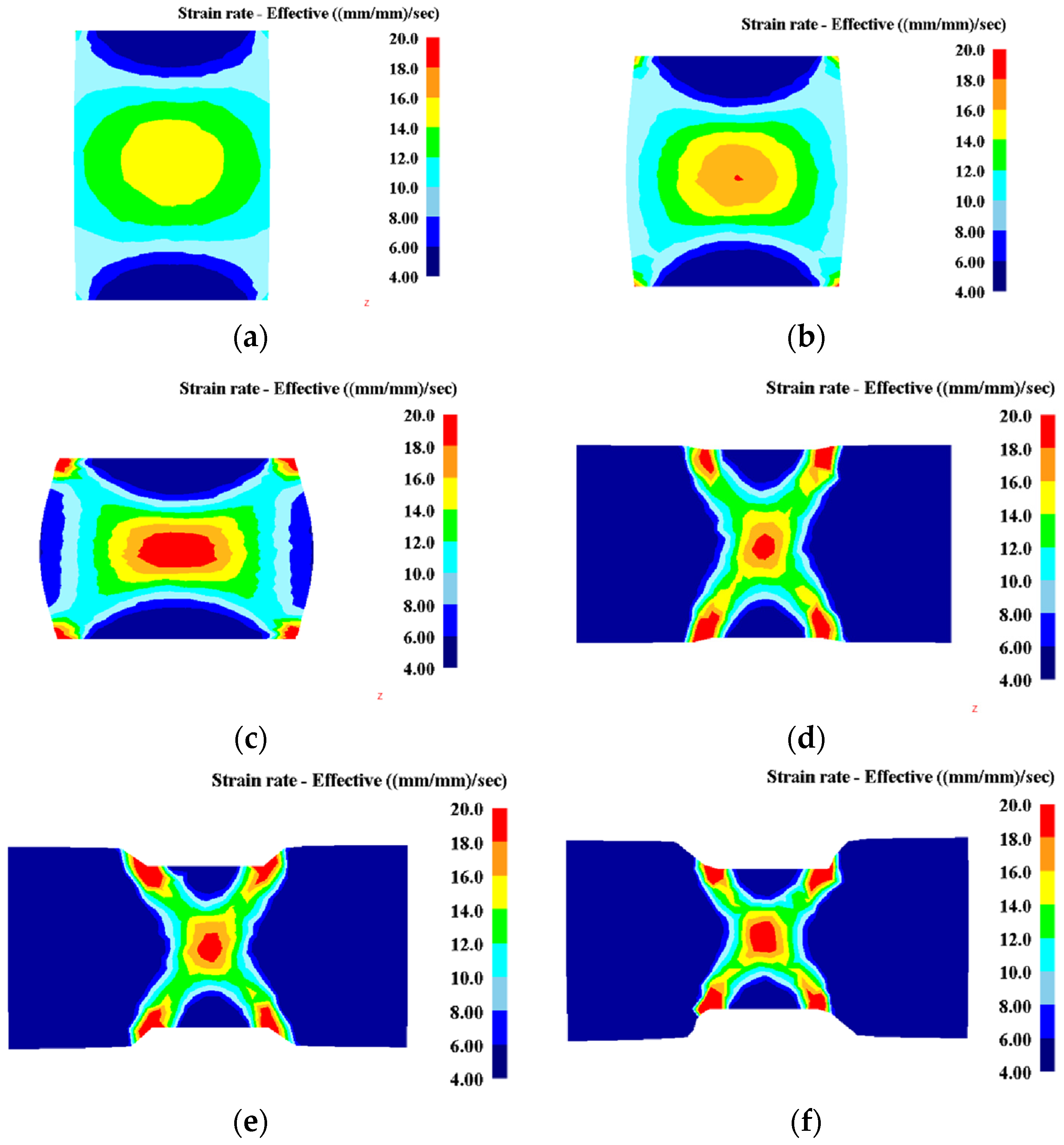
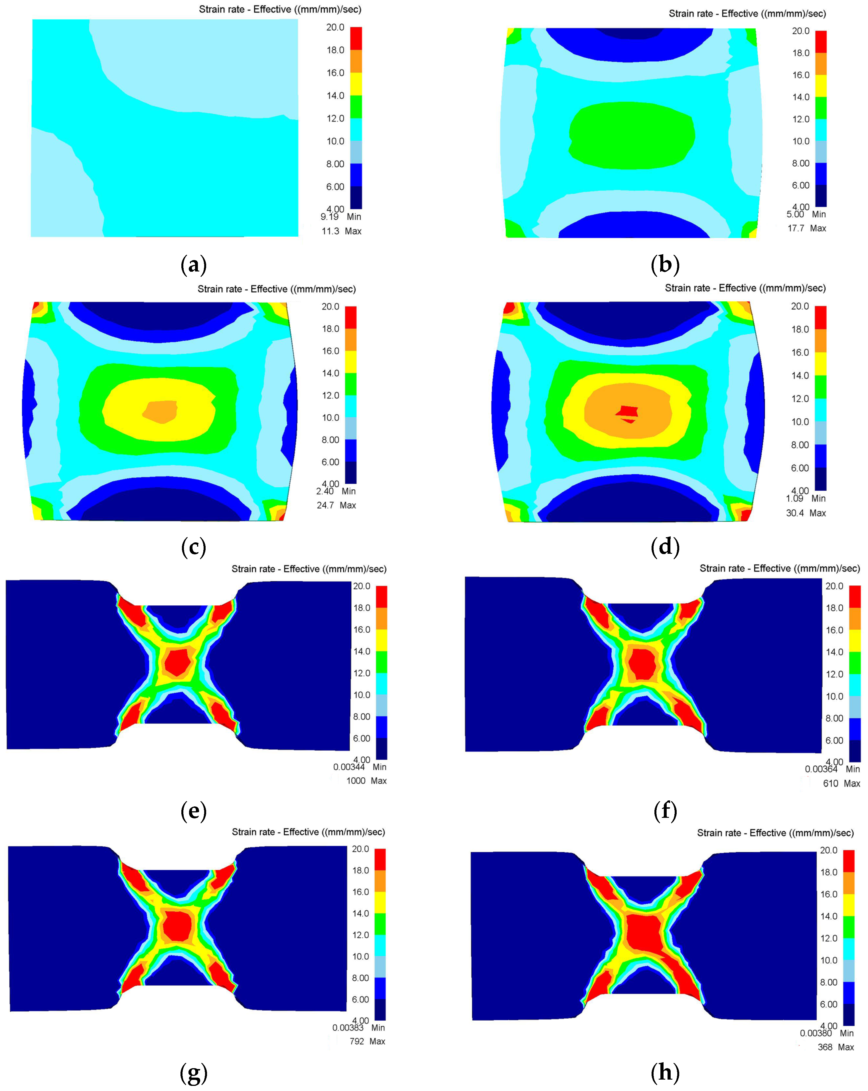
3.3. Initiation of Shear Bands

According to classical plasticity theory, shear banding depends on the initial orientation of the crystals [19] and the occurrence of shear bands are strongly dependent on various factors such as material properties, geometry, loading conditions, and friction [20]. A series of studies have been carried out to investigate the flow behavior of Ni-based alloy under uniaxial compression [3,17]. It is found that the shear band induced by uniaxial compression is much weaker than that induced by plain strain compression. It is worth noting that the Inconel 718 superalloy used in the present work has the similar material properties with those Ni-based superalloys investigated in the references [17,21], and mechanical testing was performed on similar experimental conditions by using Gleeble thermomechanical simulators. Therefore, the distinctive deformation mode of plane strain compression is expected to be the key factor for the intense occurrence of shear bands. To give a more complete insight into the initiation and evolution stages in the development of shear bands, a rigid-plastic FEM was developed to replicate the experimental results and observations.
The material parameters such as Young’s modulus, Poisson’s ratio and thermophysical parameters of Inconel 718 superalloy were quoted from Ref. [15]. Specially, the constitutive model of the present alloy has been established in our previous work [16], and it is given in the following type:
σ = 1 0.0021 ln { ( Z 1.32 × 10 16 ) 1 4.2 + [ ( Z 1.32 × 10 16 ) 2 4.2 + 1 ] 0.5 }
where Z denotes the Zener–Hollomon parameter and can be represented by the following equation:
Z = ε . exp ( 429000 R T )
where ε . is the strain rate, T is the absolute temperature and R is the universal gas constant, R = 8.314 kJ/mol.
The failure of alloys during hot-working is mainly ascribed to additional tensile stress induced by inhomogeneous deformation [22]. In the present study, the tensile stress is expressed in the form of a maximum tensile work criterion proposed by Cockroft and Latham [23]:
C = 0 ε ¯ f σ max d ε ¯
where C is the damage factor, σmax is the highest local tensile stress, ε ¯ is the true strain and ε ¯ f is the true strain at fracture. When a cylindrical specimen is uniaxially compressed as shown in Figure 4a, the additional tensile stress is localized at the equator of the bulge area (indicated by arrow). This additional stress, however, cannot give rise to the formation of shear band because the direction of the stress is along the circle and perpendicular to the primary stress axis. When the specimen is subjected to plane strain compression, as shown in Figure 4b, the stress concentration occurs in an “X” type region of the specimen. The “X” type stress concentration is supposed to be related to surface tension of the specimen and the friction during deformation. It is clear that the stress concentration significantly promotes the occurrence of shear band due to the favorable orientation. As a result, the plane strain compression is easier to induce the initiation of shear bands in comparison with uniaxial compression.
The special deformation mode of plane strain compression leads to different features of state variables such as effective strain, effective stress, temperature, etc. In the present study, strain rate is chosen as the primary field quantity to inspect, because it gives the best indication of the instantaneous tendency toward shear band formation [20]. The contours of effective strain rate for the two compression modes under the same deformation conditions are shown in Figure 5. For the uniaxial compression, a relatively small gradient was found in the strain rate contours across the cross-section at the initial stage of deformation (5% height reduction in Figure 5). In this case, the strain rate in the center area of the specimen is smaller than 15 s−1. Plastic deformation yielding 30% thickness reduction a maximum strain rate of 20 s−1 a rather rectangle region of uniform plastic deformation (in comparison to the more round strain rate distribution in Figure 5a).
On the other hand, the distribution of strain rate resulted from plane strain compression shows large gradients across the cross-section at the initial stage of deformation in Figure 5d. The distribution of strain rate is extremely nonuniform and the X-shape region can be observed through the plane strain compression process (from 5% up to 30% thickness reduction). The high strain rate region begins to rotate away from the ordinate at the very beginning of deformation, which is considered to be related with the initiation of shear band according to previous studies [20].
The interfacial friction between the die and workpiece plays an important role in the occurrence of shear bands in the compression process. Firstly, the level of friction between the die and workpiece usually increases with the increasing of deformation temperature for metals [24,25]. Therefore, the friction coefficient (f) at a high temperature cannot be ignored. According to the FEM simulation results shown in Figure 6, with the increasing of friction coefficient, the initial strain for the shear bands tends to form from the corners and center of uniaxial compression specimens, while the degree of shear banding enhances in the plane strain compression specimens. Secondly, Li et al. has found that although the friction coefficient was a constant at lower strain level, the instantaneous friction coefficient increased approximately exponentially with the true strain at higher strain level [26]. Therefore, the effect of friction on the tendency to form flow localization is enhanced in the plane strain compression process, thus promoting the occurrence of shear bands. Thirdly, as shown in Figure 4, the damage factor distributes at the equator of the cylindrical specimen (perpendicular to the primary stress axis) after uniaxial compression, while the plane strain compression leads to an “X” type stress concentration area from which the shear bands tend to initiate. This difference is associated with the frictional shear factor at the interface of die-workpiece. For uniaxial compression, a high level of friction may lead to the appearance of “dead” zones just below the die, and this can result in the “X” shear bands. However, the effect of friction will be balanced by DRX. If high strain rate, low deformation temperature or large strain is chosen, shear bands may appear. For plane strain compression, the deformation along the length direction is restricted and a large shear factor will be induced at the corners of contact surface between die and workpiece. Therefore, the “dead” zones are easier to form below the die, which promote the occurrence of shear bands.

3.4. Evolution of Shear Bands

As it has been clarified in Section 3.2, the severe deformation conditions tend to produce “S” type shear bands, while the intermediate deformation conditions prefer to induce “X” type shear bands. Note that both microstructure observations (Figure 3) and FEM simulations (Section 3.3) suggest that the morphology of shear bands at the initial stage exhibits “X” type with two crossed branches, as illustrated in Figure 7. It can be confirmed that the strength of the two branches is not exactly the same—one is “stronger” and the other one is “weaker”. The final shape of these shear bands depends on deformation conditions, interfacial friction and material properties. The evolution process is interpreted in a phenomenological way as follows.
(i)
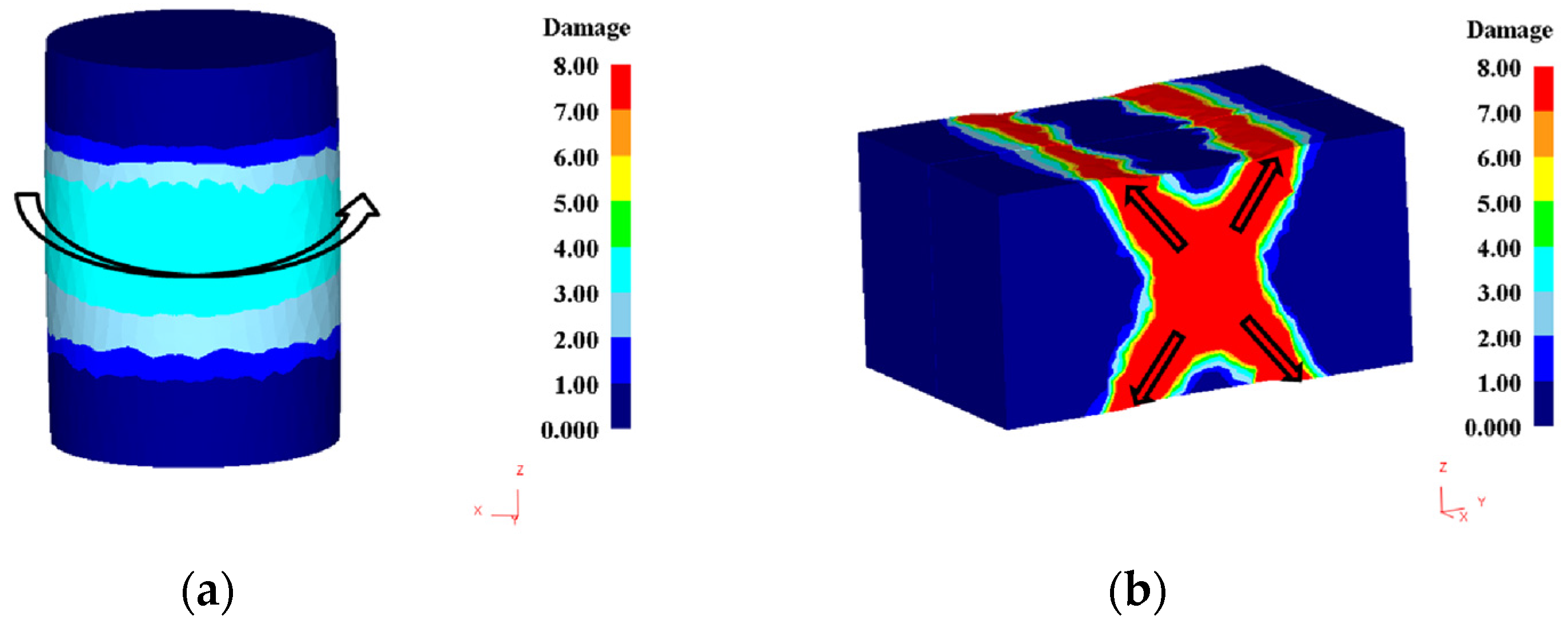
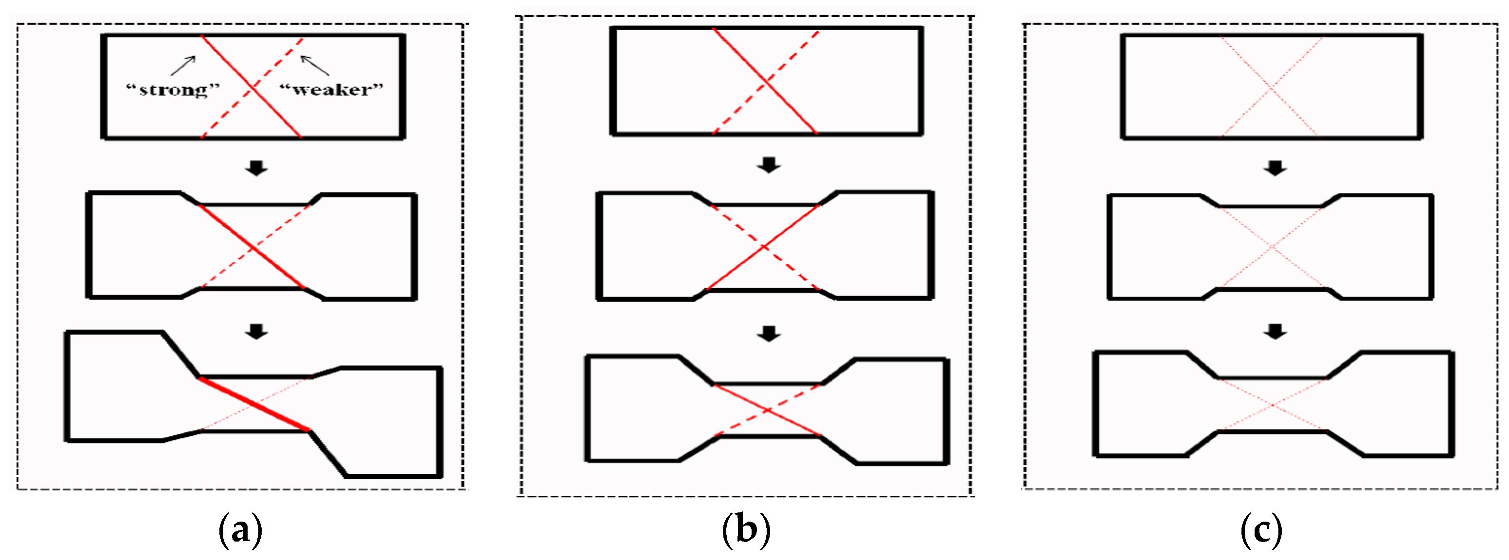
In the case of high strain rate and low temperature, one of the two branches becomes stronger, weakening the second branch. It is due to the difference of deformation-induced heating (as shown in Figure 7a) and the nonuniform of instantaneous friction. With further compression, the interaction of adiabatic heating and strain, together with the increasing of interfacial friction, promotes the propagation of the stronger branch. Since the occurrence of shear bands are associated with material elements, their directions will rotate away from the compression axis once they initiated from the deformed region. Thus, the initial shear angle will increase, and leads to the formation of an asymmetrical specimen (Figure 3a and Figure 7a) finally.
(ii)
In the case of intermediate deformation, the deformation-induced heating can be neglected due to the much lower strain rates, and thus it is no longer the key factor to determine the evolution of shear bands. Therefore, the interfacial friction (f) and inherent material property, i.e., the positive strain rate sensitivity (m), are expected to control the formation of shear bands.
As shown above, the two branches of the initial shear band are not exactly the same. They both form at the same time, however the rate along one of these branches is higher and sometimes it changes. Once the rate in one of the branches is larger, it will be strengthened due to the positive m values and then the rate will decrease. As the rates are similar along the two bands, the X-type of shear band will form. Then the deformation resistance of the former branch becomes larger than the latter one. As a result, the inhomogeneous deformation will transform from the stronger branch to the weaker one. Owing to this alternate “strengthening–relaxation” effect, the two branches develop simultaneously, and form a stable “X” type shear band. As the compressing proceeds, the intersecting shear straining leads to the formation of regions with round strain rate in the center area of the compressed specimens.
(iii)
In the case of high temperature and low strain rate, no shear bands can be found macroscopically. Even if unstable flow occurs, the “strengthening–relaxation” effect mentioned above can suppress the development of inhomogeneous deformation owing to the higher m values. Thus, homogenous microstructure can be obtained throughout the entire deformed region, as illustrated in Figure 7c.

4. Conclusions

A study of the formation and evolution of shear bands in nickel-base Inconel 718 superalloy was performed by means of plane strain compression and FEM simulation in the present work. Based on the experimental and simulation results, the influence of processing parameters on shear bands was discussed. It was found that the plane strain compression can produce strong shear bands, the morphology of which strongly depends on compressing temperature, strain rate and type of loading (plane strain versus uniaxial compression). Present analysis leads to the following conclusions:
(1)
The shape of shear bands under different deformation conditions can be divided into two categories: “S” shape for severe conditions, “X” shape for intermediate conditions.
(2)
The shear bands produced at plane strain compression propagates more rapidly than those under uniaxial compression tests. FEM simulation results of plane strain compression suggest that the shear bands are promoted by the secondary tensile stress located at the X-shape region in the specimen.
(3)
The morphology evolution of shear bands is determined by deformation conditions and interfacial friction. Compression at severe conditions yields “S” type shear bands due to the synergic effect of adiabatic heating, deforming and distributing of instantaneous friction. Because of the alternative “strengthening-relaxation” effect, intermediate conditions result in “X” type shear bands. A homogenous microstructure can be obtained throughout the entire deformed region if the metal flow is stable enough.
(4)
Due to the complex stress states and severe deformation conditions, shear bands are easy to appear during the plane strain compression process. Therefore, the influence of shear bands on strain–stress curves must be considered when the plane strain compression is applied for testing the high temperature compression properties.

Acknowledgments

This work was financially supported by the Natural Science Foundation of Shaanxi Province (2014JQ6216) and the “111” Project (No. B08040).

Author Contributions

Bin Tang and Jinshan Li conceived and designed the experiments; Lin Xiang and Liang Cheng performed the experiments; Degui Liu and Liang Cheng analyzed the data; Hongchao Kou contributed reagents/materials/analysis tools; Bin Tang wrote the paper.

Conflicts of Interest

The authors declare no conflicts of interest.

References

  1. Qu, F.S.; Liu, X.G.; Xing, F.; Zhang, K.F. High temperature tensile properties of laser butt-welded plate of IN718 superalloy with ultra-fine grains. Trans. Nonferrous Met. Soc. China 2012, 22, 2379–2388. [Google Scholar] [CrossRef]
  2. Oblak, J.M.; Pauionis, D.F.; Duvall, D.S. Cohenency strengthening in Ni-base alloys hardened by DO22 precipitates. Metall. Trans. A 1974, 5, 143–153. [Google Scholar]
  3. Wang, M.J.; Wang, W.R.; Liu, Z.L.; Sun, C.Y.; Qian, L.Y. Hot workability integrating processing and activation energy maps of Inconel 740 superalloy. Mater. Today Commun. 2018, 14, 188–198. [Google Scholar] [CrossRef]
  4. Kar, S.K.; Sondhi, S.K. Microstructure based and temperature dependent model of flow behavior of a polycrystalline nickel based superalloy. Mater. Sci. Eng. A 2014, 601, 97–105. [Google Scholar] [CrossRef]
  5. Koeller, R.C.; Raj, R. Diffusional relaxation of stress concentration at second phase particles. Acta Metall. 1978, 26, 1551–1558. [Google Scholar] [CrossRef]
  6. Rogers, H.C. Adiabatic plastic deformation. Ann. Rev. Mater. Sci. 1979, 9, 283–311. [Google Scholar] [CrossRef]
  7. Etaati, A.; Dehghani, K. A study on hot deformation behavior of Ni-42.5Ti-7.5Cu alloy. Mater. Chem. Phys. 2013, 140, 208–215. [Google Scholar] [CrossRef] [Green Version]
  8. Poliakt, E.I.; Jonas, J.J. A one-parameter approach to determining the critical conditions for the initiation of dynamic recrystallization. Acta Mater. 1996, 44, 127–136. [Google Scholar] [CrossRef]
  9. Semiatin, S.L.; Lahoti, G.D. Deformation and unstable flow in hot forging of Ti-6Ai-2Sn-4Zr-2Mo-0.1Si. Metall. Trans. A 1981, 12, 1705–1717. [Google Scholar] [CrossRef]
  10. Cheng, L.; Chang, H.; Tang, B.; Kou, H.C.; Li, J.S. Deformation and dynamic recrystallization behavior of a high Nb containing TiAl alloy. J. Alloys Compd. 2013, 552, 363–369. [Google Scholar] [CrossRef]
  11. Dehghan, H.; Abbasi, S.M.; Momeni, A.; Taheri, A.K. On the constitutive modeling and microstructural evolution of hot compressed A286 iron-base superalloy. J. Alloys Compd. 2013, 564, 13–19. [Google Scholar] [CrossRef]
  12. Cheng, L.; Xue, X.Y.; Tang, B.; Kou, H.C.; Li, J.S. Flow characteristics and constitutive modeling for elevated temperature deformation of a high Nb containing TiAl alloy. Intermetallics 2014, 49, 23–28. [Google Scholar] [CrossRef]
  13. Cheng, L.; Chang, H.; Tang, B.; Kou, H.C.; Li, J.S. Characteristics of metadynamic recrystallization of a high Nb containing TiAl alloy. Mater. Lett. 2013, 92, 430–432. [Google Scholar] [CrossRef]
  14. Patil, S.P.; Prajapati, K.G.; Jenkouk, V.; Olivier, H.; Markert, B. Experimental and numerical studies of sheet metal forming with damage using gas detonation process. Metals 2017, 7, 556. [Google Scholar] [CrossRef]
  15. Na, Y.S.; Yeom, J.T.; Park, N.K.; Lee, J.Y. Simulation of microstructures for alloy 718 blade forging using 3D FEM simulator. J. Mater. Process. Technol. 2003, 141, 337–342. [Google Scholar] [CrossRef]
  16. Cheng, L.; Xue, X.Y.; Tang, B.; Liu, D.G.; Li, J.Z.; Kou, H.C.; Li, J.S. Deformation behavior of hot-rolled IN718 superalloy under plane strain compression at elevated temperature. Mater. Sci. Eng. A 2014, 606, 24–30. [Google Scholar] [CrossRef]
  17. Wang, B.; Zhang, S.H.; Cheng, M.; Song, H.W. Dynamic recrystallization mechanism of Inconel 690 superalloy during hot deformation at high strain rate. J. Mater. Eng. Perform. 2013, 22, 2382–2388. [Google Scholar] [CrossRef]
  18. Wang, Y.; Shao, W.Z.; Zhen, L.; Yang, L.; Zhang, X.M. Flow behavior and microstructures of superalloy 718 during high temperature deformation. Mater. Sci. Eng. A 2008, 497, 479–486. [Google Scholar] [CrossRef]
  19. Jia, N.; Eisenlohr, P.; Roters, F.; Raabe, D.; Zhao, X. Orientation dependence of shear banding in face-centered-cubic single crystals. Acta Mater. 2012, 60, 3415–3434. [Google Scholar] [CrossRef]
  20. Semiatin, S.L.; Lahoti, G.D. The occurrence of shear bands in isothermal, hot forging. Metall. Trans. A 1982, 13, 275–288. [Google Scholar] [CrossRef]
  21. Tang, X.F.; Wang, B.Y.; Huo, Y.M.; Ma, W.Y.; Zhou, J.; Ji, H.C.; Fu, X.B. Unified modeling of flow behavior and microstructure evolution in hot forming of a Ni-based superalloy. Mater. Sci. Eng. A 2016, 662, 54–64. [Google Scholar] [CrossRef]
  22. Domanti, A.T.J.; Horrobin, D.J.; Bridgwater, J. An investigation of fracture criteria for predicting surface fracture in paste extrusion. Int. J. Mech. Sci. 2002, 44, 1381–1410. [Google Scholar] [CrossRef]
  23. Cockroft, M.G.; Latham, D.J. Ductility and the Workability of Metals. J. Inst. Met. 1968, 96, 33–39. [Google Scholar]
  24. Shahriari, D.; Sadeghi, M.H.; Ebrahimi, G.R.; Kim, K.T. Effects of lubricant and temperature on friction coefficient during hot forging of Nimonic 115 superalloy. Kovove Mater. 2011, 49, 375–383. [Google Scholar] [CrossRef]
  25. Rudkins, N.T.; Hartley, P.; Pillinger, I.; Petty, D. Friction modelling and experimental observations in hot ring compression tests. J. Mater. Process. Technol. 1996, 60, 349–353. [Google Scholar] [CrossRef]
  26. Li, Y.P.; Onodera, E.; Chiba, A. Friction coefficient in hot compression of cylindrical sample. Mater. Trans. 2010, 51, 1210–1215. [Google Scholar] [CrossRef]
Figure 1. Initial microstructure of the received Inconel 718 superalloy.
Metals 08 00141 g001
Figure 2. Typical true stress–true strain curves of Inconel 718 superalloy at (a) 900 °C and (b) 10−2 s−1.
Metals 08 00141 g002
Figure 3. Etched microstructures of Inconel 718 superalloy deformed at (a) 900 °C/10 s−1; (b) 950 °C/0.001 s−1; (c) 1050 °C/0.01 s−1; (d) 1050 °C/0.001 s−1.
Metals 08 00141 g003
Figure 4. The distribution of damage factor in Inconel 718 superalloy after 5% deformation under (a) uniaxial and (b) plane strain compression.
Metals 08 00141 g004
Figure 5. The distribution of the effective strain-rate in Inconel 718 superalloy under (ac) uniaxial compression and (df) plane strain compression at height reduction of (a,d) 5%; (b,e) 20%; (c,f) 30%.
Metals 08 00141 g005
Figure 6. Effective strain-rate distribution of Inconel 718 superalloy under (ad) uniaxial compression and (eh) plane strain compression at height reduction of 30% for different friction conditions, (a,e) f = 0, (b,f) f = 0.1, (c,g) f = 0.2, (d,h) f = 0.3.
Metals 08 00141 g006
Figure 7. Morphology evolution of shear bands during plane strain compressing process at (a) severe conditions; (b) intermediate conditions and (c) mild conditions.
Metals 08 00141 g007
Table 1. Chemical composition of the present Inconel 718 superalloy.
ElementNiCrNbMoTiAlCo.SiMnTaCuCFe
wt. %53.0218.505.343.261.040.520.120.080.0540.0500.0480.029Bal.
Table 2. The occurrence of shear band in Inconel 718 superalloy under plane strain compression.
10 s−11 s−10.1 s−10.01 s−10.001 s−1
900 °CSSXXX
950 °CSSXXX
1000 °CSXXXX
1050 °CSXXXO
S: severe shear bands observed with “S” shape; X: weak shear bands observed with “X” shape; O: Uniform plastic deformation.

