Article

Influence of CO2 Shielding Gas on High Power Fiber Laser Welding Performance

Hunan Provincial Key Laboratory of High Efficiency and Precision Machining of Difficult-to-Cut Material, Intelligent Manufacturing Institute of HNUST, Hunan University of Science and Technology, Xiangtan 411201, China
*
Author to whom correspondence should be addressed.
Metals 2018, 8(6), 449; https://doi.org/10.3390/met8060449
Submission received: 31 May 2018 / Revised: 31 May 2018 / Accepted: 9 June 2018 / Published: 13 June 2018

Abstract

:
The weldabilities were investigated during 10 kW high-power fiber laser welding of 304 stainless steel with the shielding gases of 100% Ar, 80% Ar + 20% CO2 and 100% CO2, respectively. As the proportion of CO2 in shielding gas increased from 0% to 20% then to 100%, the molten pool became unstable and the optional parameter range for obtaining a good weld appearance became narrow. The defocused distance was more negative during the CO2 shielded welding, where the weld joint without apparent defect, the maximum penetration, and a necking of weld width were formed. Porosity has been suppressed and eliminated in the CO2 shielded weld joint. The highest microhardness was obtained from the Ar + CO2 shielded weld joint, because the denser δ-ferrite appeared in the Ar + CO2 shielded weld joint. The microhardness of CO2 shielded weld joints was relative low because of the oxidation of the elements of C, Si, Mn, and Cr, which reduces the solid solution hardening tendency during the welding process.

1. Introduction

As an advanced welding technology, high-power fiber laser welding of thick plate stainless steel has been widely researched. The investigations demonstrated that weld defects, including spatter, porosity, and hump, were easily generated during laser welding of thick plates, due to its complex and volatile metallic vapor flow and molten pool [1,2]. The complex welding process was affected by various factors, such as power density, defocused distance, welding speed, and so on. Among these factors, the shielding gas was one of the most influential on the quality of welding [3,4].
When the types and proportions of mixed shielding gases were changed during laser welding, the rules of absorption and scattering for the laser beam were studied through theoretical calculations [5]. The results showed that a certain proportion of He added to the Ar was helpful to reduce the absorption and scattering of the laser beam, due to the fact that the ionization potential of He is larger than that of Ar. When N2, O2, and H2 were added to Ar, the absorptions and scatterings for the laser beam were similar at the same temperature, because the ionization potentials of N2, O2, and H2 are similar to that of Ar. Seto et al. [6] studied the behaviors of plasma and keyhole during the CO2 laser welding with He and N2 as shielding gases. It was concluded that the keyhole was continuously opening during He shielded welding, while it was periodically closed during the N2 shielded welding, since the incident laser could be absorbed and shielded by N2 plasma. When N2 plasma appeared in the short cycle, the bubbles formed in the molten pool were able to escape; as such, porosity could be eliminated or reduced. Katayama et al. [7] studied the influence of shielding gas on porosity during fiber laser welding of stainless steel. Research showed that the generation of weld porosity was mainly due to the unstable keyhole, whose internal collapse led to the formation of bubbles in the molten pool, which then transformed into porosities after solidification. In comparison to Ar and He, the N2 shielding gas was shown to reduce the porosities. The reason for this was that N2 could dissolve into the weld joint when bubbles of the N2 shielding gas became trapped in the molten pool. Thus, after solidification, the probability of porosity formation was significantly reduced. Zhao et al. [8] studied the influences of O2 as a shielding gas on molten pool behavior and weld penetration during laser spot welding in the conduction mode. They showed that when the content of O2 exceeded a certain amount, the flow direction of the molten pool surface turned from outward to inward, and the weld penetration and inter width of weld joint were increased. Zhao et al. [9,10] studied the influence of He containing 10% O2 on weld formation and porosity during fiber laser welding and fiber laser-arc hybrid welding of steel. The results showed that a small amount of O2 in the shielding gas could combine with C in the base metal to form CO2. That was helpful for increasing the pressure inside the keyhole, so as to increase the outlet diameter of the keyhole, and to promote its stability. Thus, the vapor could flow out of the keyhole smoothly, and porosities in weld joint were reduced.
As an active shielding gas, CO2 is added to the inert gas in shield welding. It was also reported that pure CO2 has been used in shield welding. Li et al. [11] investigated the influence of CO2 added in the inert shielding gas on arc shape and droplet transfer in high-strength, low-alloy steels gas metal arc welding processes. It was concluded that the arc stiffness was improved, and a complete fusion of sidewalls was obtained when CO2 was added to the inert shielding gas. Wahba et al. [12] studied the weldability of K36D shipbuilding steel in a T-joint using fiber laser-arc hybrid welding with 100% CO2 as a shielding gas. In comparison to the mixed shielding gas 80% Ar + 20% CO2, 100% CO2 had both advantages and disadvantages. The advantage was that it could increase weld penetration and limit the production of weld porosities. The disadvantage was that it produced a large number of spatters, and an irregular weld appearance. Pan et al. [13] have studied the welding process and properties during fiber laser-arc hybrid welding of high strength steel with shielding gases of 80% Ar + 20% CO2 and 100% CO2. The effects of 100% CO2 were demonstrated to be consistent with the conclusions revealed by Wahba et al. In addition, it was observed that the deep keyhole was more stable, and the process window of laser power conditions for the formation of sound welds was much wider in 100% CO2 shielded welding. The spatters could be improved by adjusting the parameters of the arc properly in 100% CO2 shielded welding [12]. These investigations indicated that it was possible that CO2, an inexpensive shielding gas, could take the place of Ar to yield good welding performance during laser-arc hybrid welding processes.
However, the influences of CO2 shielding gas on welding performance during high power fiber laser welding have not been fully investigated. Therefore, the present work focused on the influences of CO2 shielding gas on weld appearance and weld formation during 10 kW high power fiber laser welding of 304 stainless steel. The formation of welding porosity, differences of metallographic structure, and the hardness of weld fusion zones were compared and studied using different shielding gases.

2. Materials and Methods

The experiments were carried out using a high power fiber laser system (Fiber Laser YLS-10000, IPG Photonics Corporation, Oxford, MA, USA); continuous-wave laser; wavelength of 1.07 μm; beam parameter product (BPP) of 7.5 mm·mrad; maximum power of 10 kW). The laser beam was transmitted through an optical fiber with 200 μm diameter, and focused by a lens with a 300 mm focal distance. The focal spot diameter was 0.4 mm.
The material used in this study was a 304 austenitic stainless steel thick plate, whose chemical composition is listed in Table 1. The surface of the 304 stainless steel plate was cleaned with alcohol before welding. In the experiments, the laser beam was scanned on the 304 stainless steel thick plate to form a bead-on-plate weld. The laser power was fixed to be 10 kW. Three kinds of shielding gases, 100% Ar, 80% Ar + 20% CO2, and 100% CO2, were adopted during the welding process (simplified as Ar, Ar + CO2 and CO2 hereafter). One kind of shielding gas was used during the one path welding process. The flow rate of the shielding gas was fixed at 30 L/min. The shielding gas was blown through a nozzle with an outlet diameter of 6 mm from a 45 degree angle, in a front-blow arrangement. The defocused distance (Df) was set from −10 mm to +5 mm, and welding speed (V) was set within a range from 1 m/min to 3 m/min. Experimental parameters are listed in Table 2.
After welding, the appearance of weld joints was first observed and analyzed. The porosities in weld joints were observed using an XYD-2510/3 X-ray transmission detector (Huangshihuabao Testing Equipment Co. Ltd., Huangshi, China). Then, cross sections of weld joints were obtained, and the specimens were prepared to observe micro-features, after grinding and polishing to a bright finish surface using a diamond polishing paste (diamond size 2.5 µm), and corroded using aqua regia. The weld geometry was observed by an optical microscope, and then weld penetration was obtained. The metallographic structure of weld joints was observed by a VHX-500FE digital microscope (KEYENCE Corporation, Osaka, Japan) with super wide-field view. Based on the observed results, the characteristics of weld formation and weld microstructures under different welding parameters and different shielding gases were analyzed and compared. Then, the microhardness of the weld joints and base metal (BM) was measured and compared. Tests for microhardness were performed on a HVS-1000A Vickers microhardness tester (Laizhou Huayin Test Instruments Co. Ltd., Yantai, China) with a load of 300 g on the indenter for 10 s.

3. Results and Discussion

3.1. Influence of Shielding Gas on Weld Formation

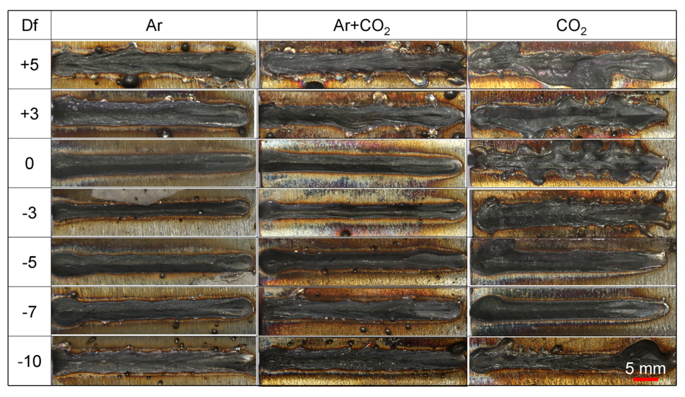
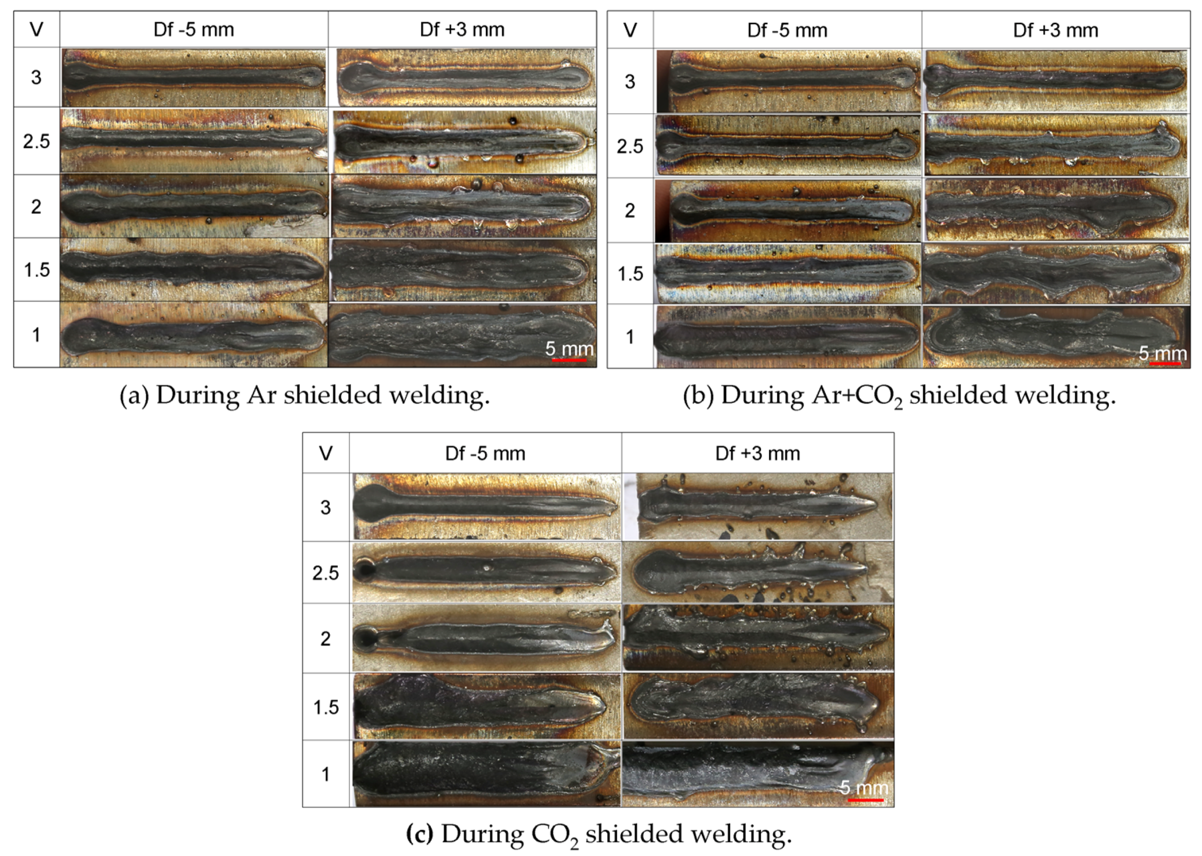
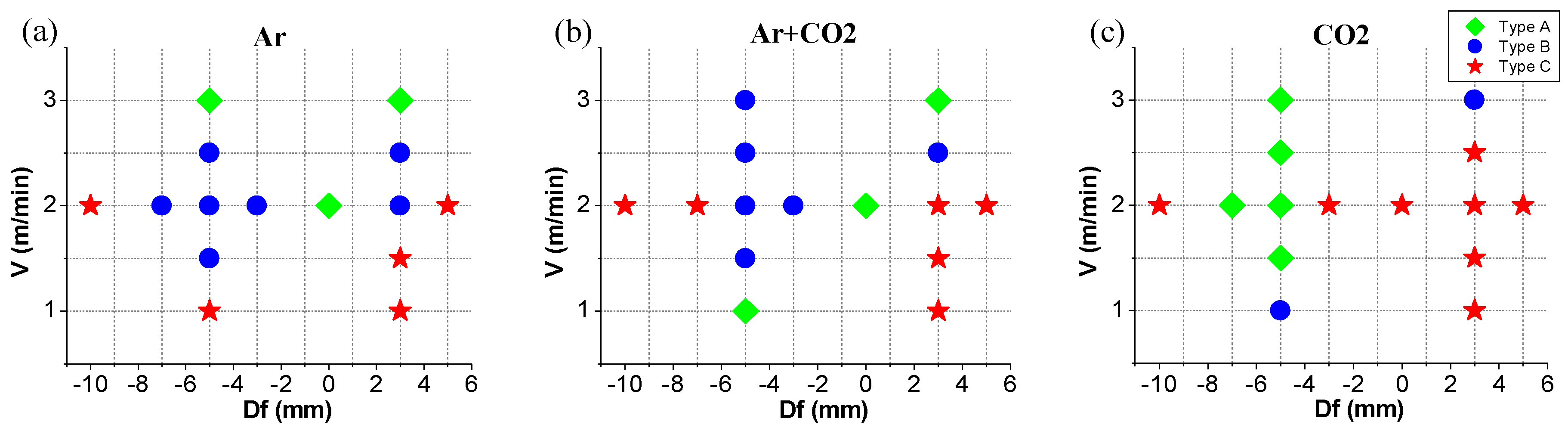
3.1.1. Weld Appearance

Figure 1 shows weld appearances under different shielding gases and Df when the V was fixed at 2 m/min. Figure 2a–c shows weld appearances under different V during Ar, Ar + CO2, and CO2 shielded welding processes, respectively.
As shown in Figure 1 and Figure 2, the weld appearances presented three typical morphologies with changes of Df and V: Type A weld joints with a continuous and smooth weld appearance and no spatter; Type B weld joints with a continuous and smooth weld appearance and a small amount of spatter; Type C weld joints with non-continuous and unsmooth weld appearance, and a lot of spatter. Type A weld joints displayed no defect on the surface. Type B weld joints were acceptable. Type C weld joints were unacceptable.
It can be seen from Figure 1 that the weld surface was non-continuous and unsmooth, with a large amount of spattering when the Df was positive or larger negative. The investigations indicated that the presence of lots of spatters and unsmooth weld joints implied an unstable welding process and a frequently fluctuating molten pool, while a stable molten pool was helpful for obtaining weld joints with a good appearance [2]. Therefore, the molten pool was unstable with positive Df or larger negative Df in the welding experiment.
As shown in Figure 1, during the Ar-shielded welding, Type C weld joints appeared when the Df was +5 mm and −10 mm, Type B welds joints when the Df was between +3 mm and −7 mm, and Type A when the Df was 0 mm. During Ar + CO2 shielded welding, Type C weld joints appeared when the Df was +5 mm, +3 mm, −7 mm and –10 mm, Type B weld joints appeared when the Df was between 0 mm and −5 mm, and Type A when the Df was 0 mm. During CO2 shielded welding, Type A weld joints appeared only when the Df was −5 mm and −7 mm, while the others were unacceptable Type Cs. It was indicated that, with the increased proportion of CO2 in the shielding gas, the number of Type C weld joints increased. This implied that the CO2 contributed to promoting fluctuation of the weld pool, the production of spatter, and the formation of unacceptable weld appearance. Similar results had also been demonstrated in other research [12,13]. The reason for this was that CO2 can easily be heated and decomposed into CO and O2 during laser welding. CO2 and CO had lower ionization potentials compared to Ar (14.4 eV ionization potential for CO2, 14.1 eV for CO, and 15.76 eV for Ar). Thus, CO2 and CO can easily be ionized to form a higher particle density than Ar. Therefore, the pressure of plasma and vapor inside the keyhole was higher in CO2 shielded welding than in Ar shielded welding. Moreover, as an active gas, O2 can reduce the viscosity of molten metal and the surface tension of the molten pool. Therefore, the weld pool could easily be squeezed out to produce spatter under the higher pressure of plasma and vapor during CO2 shielded welding.
As shown in Figure 2a, weld appearance became unsmooth when V was at 1 m/min during Ar shielded welding with a Df of −5 mm. As shown in Figure 2a,b, weld appearances were well-formed and not affected by V during Ar + CO2 and CO2 shielded welding with a Df of −5 mm. Nevertheless, the weld joint was oxidized when the V was 1 m/min with the CO2 shielded welding. Weld appearances changed gradually, to be continuous and smooth with the increase of V when the Df was +3 mm during welding with the three types of tested shielding gases. It was indicated that when the Df was positive, the molten pool became more stable as the V changed from 1 m/min to 3 m/min, since the energy input became smaller.
Figure 3a–c summarizes all types of weld appearances presented in Figure 1 and Figure 2, in order to make a direct comparison of the influence rules of different shielding gases on weld appearance morphologies. As shown in Figure 3, unacceptable Type C weld joints appeared most frequently during CO2 shielded welding, while they appeared least often during Ar shielded welding. It follows that the optional parameter range for obtaining a good weld appearances is relatively wide in the case of Ar shielded welding, while it is relatively narrow for CO2 shielded welding. Moreover, the Df where the Type A weld joint was formed became more negative during CO2 shielded welding than during Ar and Ar + CO2 shielded welding. When shielded by CO2, and set to a negative Df of −5 mm, Type A weld joints formed more easily.

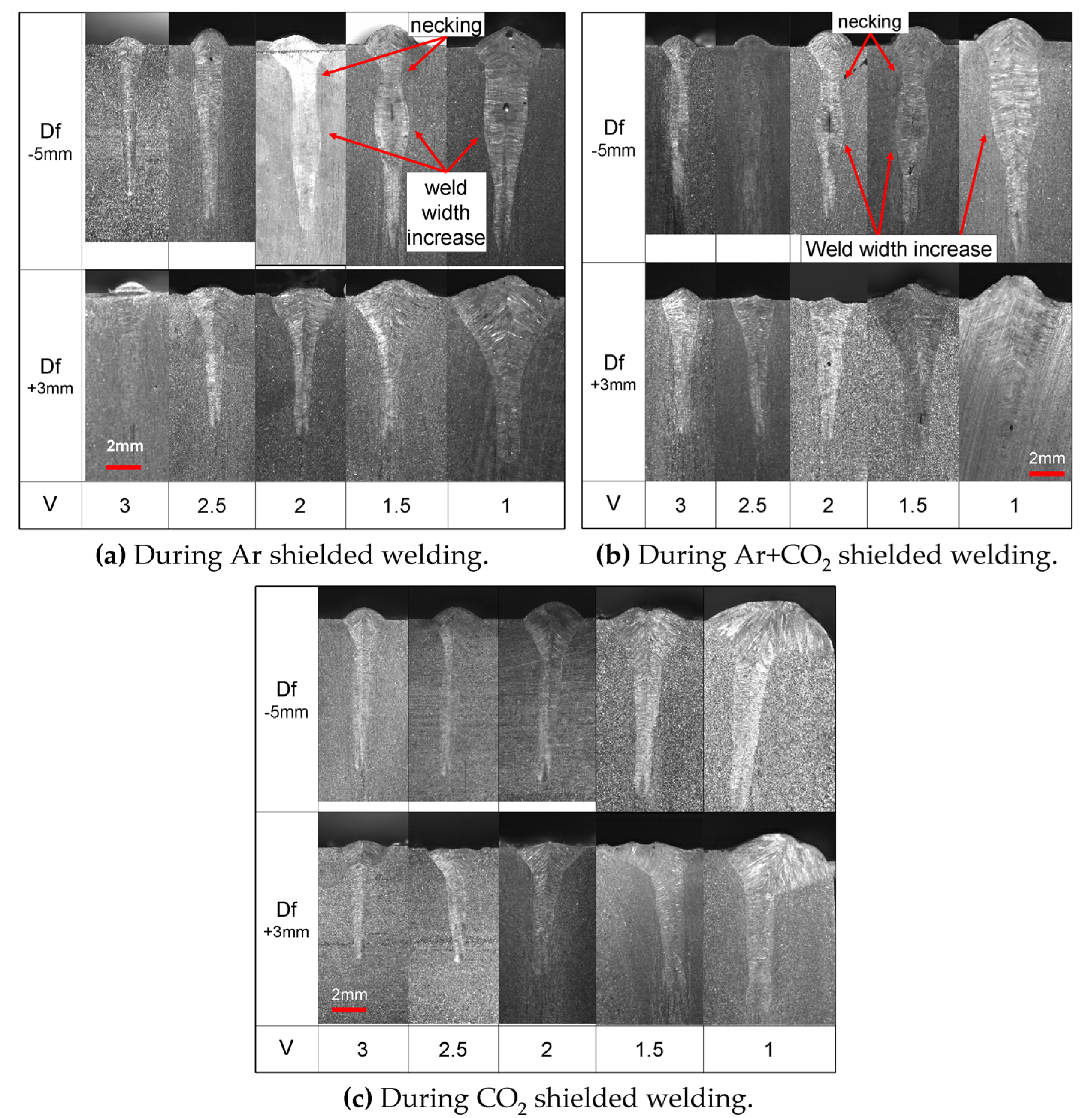
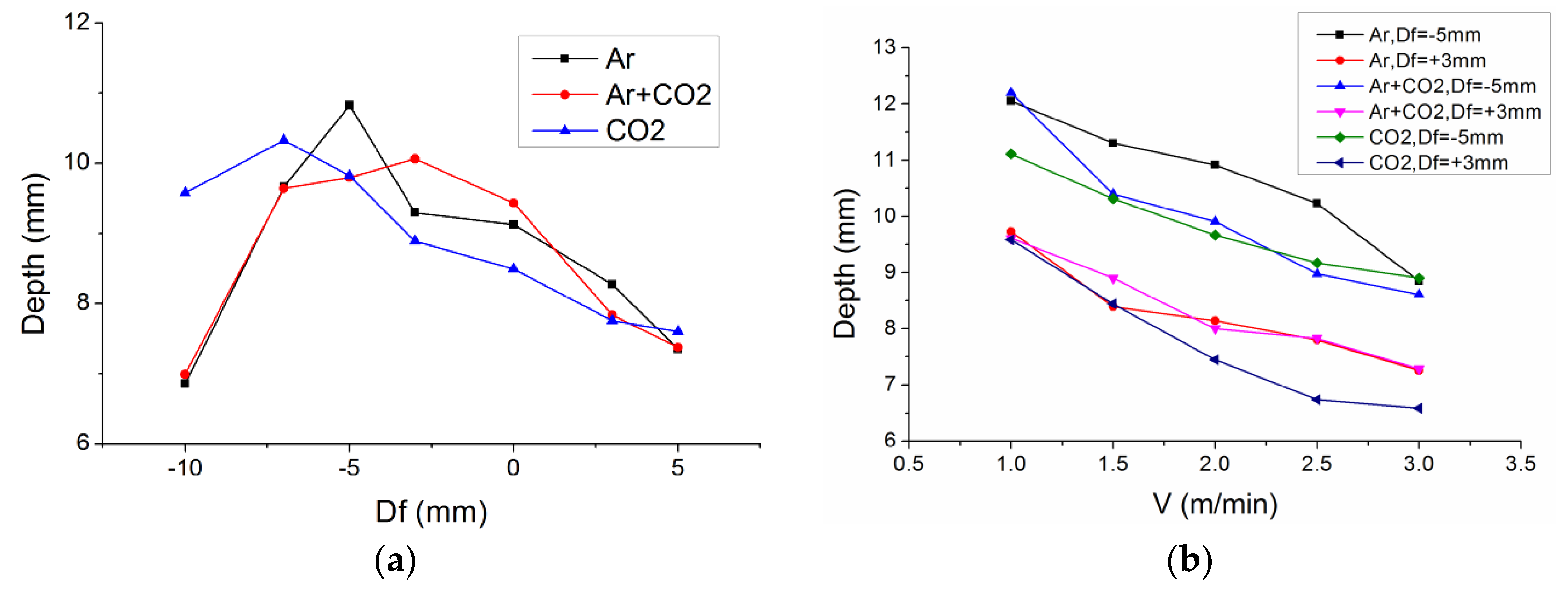
3.1.2. Cross Section Geometry of Weld Joint

Figure 4 shows the cross section geometry of weld joints made with different shielding gases and Dfs, when V was set at 2 m/min. Figure 5a–c shows the cross section geometry of weld joints under different Vs during Ar, Ar + CO2, and CO2 shielded welding processes, respectively. Figure 6a shows the variation of weld penetration, along with different Dfs and shielding gases when the V was 2 m/min. Figure 6b shows the variation of weld penetration, along with different Vs and shielding gases.
As shown in Figure 4, weld reinforcement was reduced, and weld depression occurred when the Df was positive or larger negative, due to welding spatters which caused a large amount of material loss. As shown in Figure 4 and Figure 6a, the maximum weld penetrations occurred at a Df of −5 mm, −3 mm and −7 mm during Ar, Ar + CO2, and CO2 shielded welding processes, respectively. When the Df was within the range of −5 mm to +3 mm, the penetrations of the CO2 shielded weld joints were lower than those of the Ar shielded weld joints. This means that CO2, as an active shielding gas, had no significant effect on improving the weld penetration compared with the results revealed by Wahba et al. [12] during laser-arc hybrid welding. In contrast, the Df where the maximum weld penetration occurred was relatively more negative during CO2 shielded welding than during Ar and Ar + CO2 shielded welding. This can be attributed to molten pool behaviors which were different under different shielding gases. During CO2 shielded welding, the relative stable molten pool appeared under a negative Df.
In addition, interesting weld geometry characteristics were observed, and are shown in Figure 4. During Ar and Ar + CO2 shielded welding with Df of −3 mm and −5 mm, the weld width increased at a certain depth inside the weld joint, and the necking of weld width occurred near the top surface of the weld joint. When a sudden increase of weld width occurred, the necking characteristic was brought out. During CO2 shielded welding, these weld joint shapes occurred when the Df was −10 mm. Such special weld joint shapes are also shown in Figure 5a,b when the Df was negative. The results indicated that the phenomena of a sudden increase and necking of weld width had a closer relationship with Df than with V. The previous research on behaviors of molten pools during laser welding revealed that the accumulation of high temperature molten metal at the top surface and inside the molten pool could lead to a wider weld at the upper part, and a certain depth inside the weld joint, respectively [14]. The accumulation of molten metal was related to the flow behavior of molten pool, and was affected by welding conditions. Based on these conclusions, it could be confirmed that the flow behaviors of the molten pool were different under different shielding gases. Therefore, the maximum weld penetration, and a sudden increase and necking of weld width, were observed at different Df.
As shown in Figure 5 and Figure 6b, the weld penetration and weld width increased gradually with a decrease of V. As shown in Figure 6b, when the Df was −5 mm, most penetrations of the Ar + CO2 shielded weld joints were similar to those of the CO2 shielded weld joints at the same V, but were smaller than those of the Ar shielded weld joints. This indicated that a small amount of CO2 added to the Ar had an obvious influence on weld penetration when the Df was −5 mm. The reason for this was that the molten pool was relatively stable during welding with a Df of −5 mm; therefore, a small amount of CO2 added to the Ar could absorb some laser energy through the decomposition and ionization of CO2 and subsequent reduction of the weld penetration. However, when the Df was +3 mm, most penetrations of the Ar + CO2 shielded weld joints were similar to those of the Ar shielded weld joints, but bigger than those of the CO2 shielded weld joints. This meant that a small amount of CO2 added to the Ar had almost no influence on weld penetration when the Df was +3 mm. This is because the molten pool was unstable, with lots of spatters during welding with a Df of +3 mm, and the reduction of a small amount of laser energy caused by a small amount of CO2 was unimportant compared to the energy lost by spatters. In contrast, when the shielding gas was 100% CO2, an obvious decrease of weld penetration was observed during welding with a Df of +3 mm, as shown in Figure 6b.

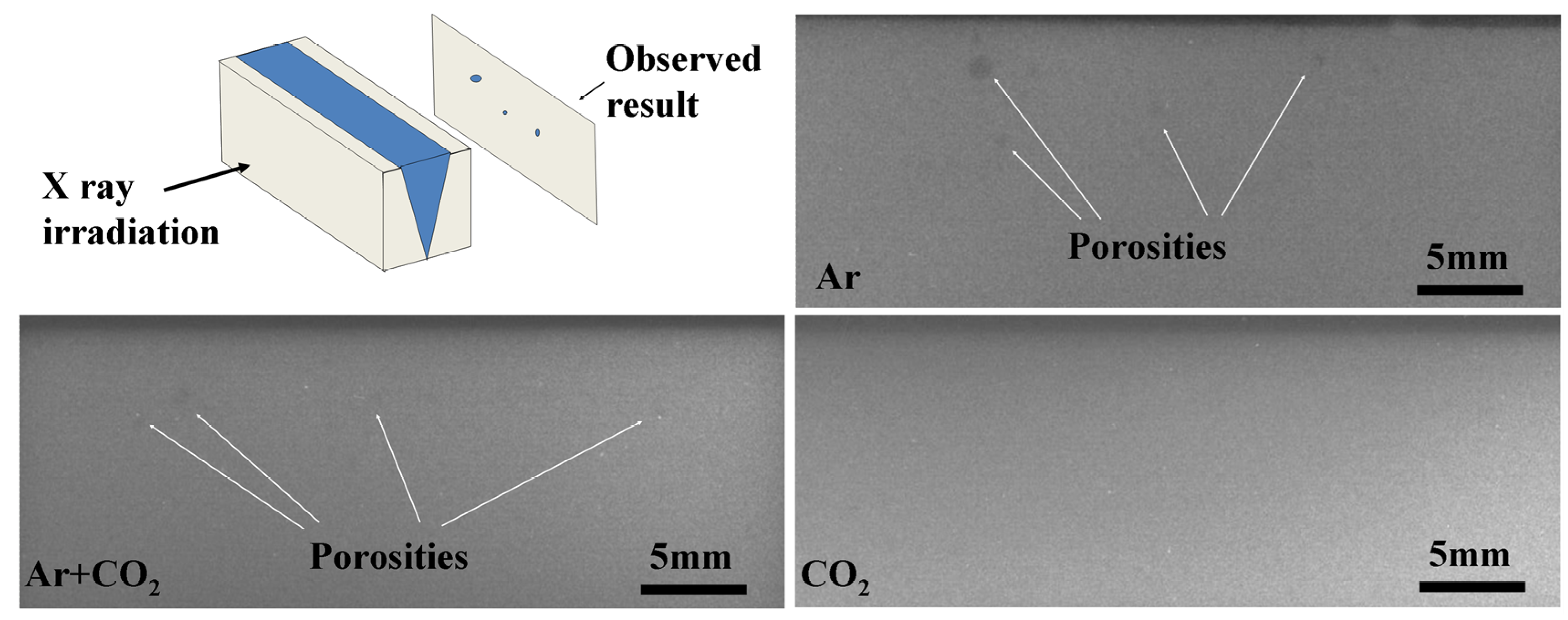
3.1.3. Weld Porosity

As shown in Figure 4 and Figure 5, the porosity in weld joints was observed during Ar and Ar + CO2 shielded welding processes. However, it was not observed in the CO2 shielded weld joints. To confirm these results, the porosities in Type A weld joints shielded by different gases (as shown in Figure 3) were detected using an X-ray transmission detector. The detected results are shown in Figure 7. It was confirmed that porosities occurred both in the Ar and Ar + CO2 shielded weld joints, but not in the CO2 shielded weld joint. This was consistent with the result obtained during hybrid welding with CO2 shielding gas in the literature [12,13]. The reason for this was that the outlet of the keyhole was bigger due to the higher pressure of CO2 plasma and vapor when CO2 was decomposed and ionized during CO2 shielded welding. Thus, the probability of keyhole collapse was reduced. Moreover, the active oxygen element decomposed from CO2 could increase the fluidity of molten metal, which could promote the escape of bubbles produced by keyhole collapse. Therefore, the inner porosity of weld joints was eliminated during CO2 shielded welding.

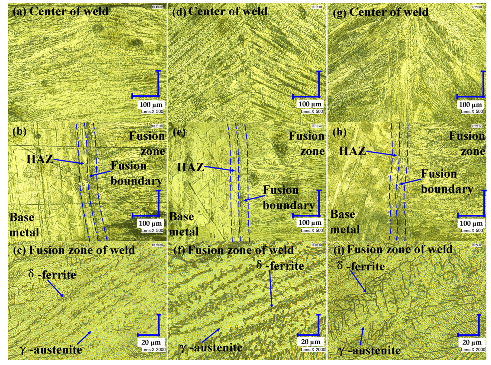
3.2. Influence of Shielding Gases on Metallographic Structure

The microstructures of weld joints shielded by different gases are shown in Figure 8. The images of Figure 8a,d,g were obtained from the fusion zone of weld joints under a microscope at 500× magnification. The images of Figure 8b,e,h were obtained from the fusion boundary of weld joints under a microscope at 500× magnification. Finally, the images of Figure 8c,f,i were obtained from the fusion zone of weld joints under a microscope at 2000× magnification. Figure 8a–c were shielded by Ar; Figure 8d–f were shielded by Ar + CO2; and Figure 8g–i were shielded by CO2. The darker, interdendritic phase in metallographs was δ-ferrite and the light-colored phase was γ-austenite. The interdendritic δ-ferrite was sparse in the γ-austenite phase in the Ar shielded fusion zone, but was denser both in the Ar + CO2 and CO2 shielded fusion zone. The interdendritic δ-ferrite in Ar was lathy, short strip, trivial, and in scattered distribution. The interdendritic δ-ferrite was continuous, thick-long strip, with short, secondary dendrite arms and punctiform structures in Ar + CO2. This appeared in a skeletal-network structure in the CO2 shielded fusion zone, where the γ-austenite was separated into different regions. As illustrated in the literature [13,15], lots of oxide inclusions could form in the CO2 shielded weld joint, which could promote the formation of separated γ-austenite during the transformation from δ-ferrite to γ-austenite. Thus, the interdendritic δ-ferrite changed from a scattered strip to a continuous long strip, then to a skeletal-network structure, as the shielding gases changed from Ar to Ar + CO2 then to CO2. The fusion boundaries between weld joints and BM are shown in Figure 8b,e,h. The width of the fusion boundary in all weld joints was similar, i.e., below 50 μm. By comparison, the grain in the fusion zones of weld joints was obviously finer than that of the BM. Meanwhile, the width of the heat-affected zone (HAZ) in all weld joints was similar, i.e., below 50 μm. This implied that high power laser welding of thick plates greatly reduced the tendency of softening in HAZ.

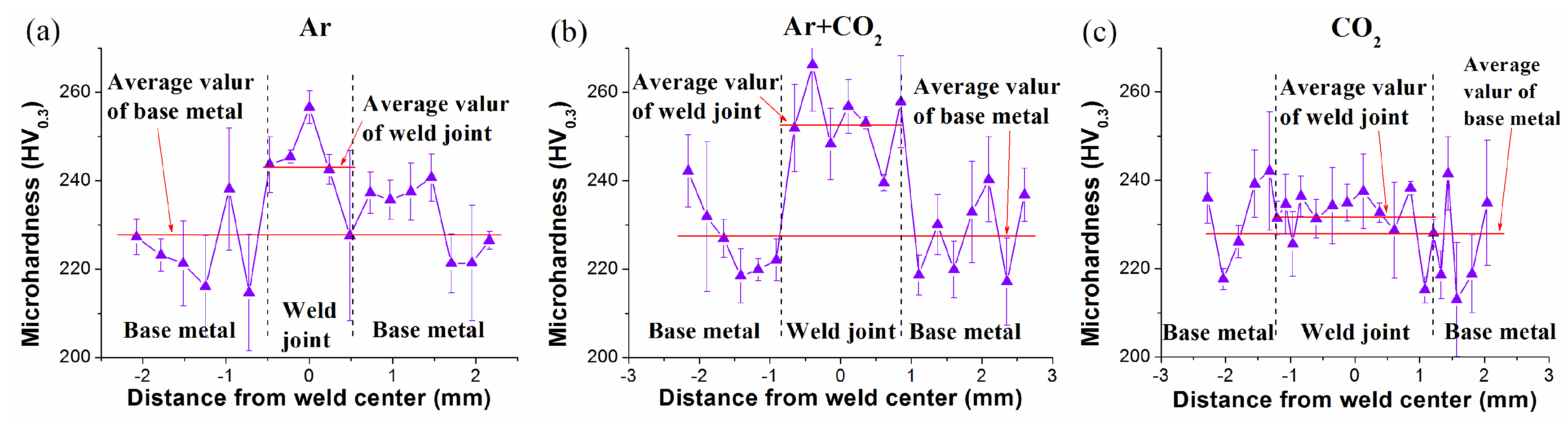
3.3. Influence of Shielding Gases on Microhardness

The microhardness of weld joints shielded by different gases is shown in Figure 9a–c; this was obtained from the detection of the three kinds of weld joints depicted in Figure 8. As shown in Figure 9, the average microhardness of weld joints shielded by the three kinds of shielding gases was higher than that of BM. The highest average microhardness was obtained from the Ar + CO2 shielded weld joint, while the lowest was obtained from the CO2 shielded weld joint, among the three kinds of weld joints studied. The different microhardnesses of BM and weld joints shielded by different gases was closely related to metallographic characteristics. As shown in Figure 8, the grain size of BM was much bigger than that of all weld joints, resulting in the lower microhardness of BM. As mentioned above, the interdendritic δ-ferrite was denser in the Ar + CO2 shielded weld joint than that of the Ar. The interdendritic δ-ferrite appeared in thick-long strips, with lots of short secondary dendrite arms, and q punctiform structure in the Ar + CO2 shielded weld joint, which were beneficial for increasing the strengthening effect of the grain boundary, and for obtaining higher microhardness than with the Ar shielded weld joint.
For the CO2 shielded weld joint, although the interdendritic δ-ferrite was as dense as that of the Ar + CO2 shielded weld joint, the δ-ferrite structure changed, to for a skeletal-network structure. The strengthening effect of the grain boundary of the skeletal-network structure was thus reduced; the microhardness of the CO2 shielded weld joint was lower than that of the Ar + CO2 shielded weld joint. Furthermore, as discussed in the literature [15], the levels of C, Si, and Mn in the CO2 shielded weld joint would be decreased, because they were oxidized to form oxide inclusions, and thus, the quench hardening tendency was reduced and the impact toughness was increased during CO2 shielded welding. As illustrated in the literature [13,15], lots of oxide inclusions were observed in the CO2 shielded weld joint. Compared with the BM, the contents of C, Si, Mn, and Cr increased the oxide inclusion, which meant that these elements in metallographic phases were relatively decreased compared with conditions with no oxide inclusion. Therefore, the effects of solid solution hardening caused by the contents of C, Si, Mn, and Cr were reduced in the CO2 shielded weld joint. Thus, q lower microhardness was obtained with the CO2 shielded weld joint.

3.4. Discussion on Selection of Shielding Gas during Laser Welding Stainless Steel

Based on a comprehensive analysis of weld appearances, porosities and microhardnesses, the selection of a shielding gas for the laser welding of stainless steel is discussed. As indicated in Figure 3, the widest optional parameter range for good weld appearance existed for Ar shielded welding, followed by Ar + CO2 shielded welding. However, porosities were observed in both the Ar and Ar + CO2 shielded weld joints. During CO2 shielded welding, although the optional parameter range for obtaining an acceptable weld appearance was narrow, weld porosity could be suppressed and eliminated. Moreover, the microhardness of all weld joints was higher than that of BM, and the Ar + CO2 shielded weld joint had the highest microhardness of all types tested. It could be seen that the three kinds of shielding gases each had both advantages and disadvantages. Therefore, the appropriate shielding gas should be selected according to the application demands and welding requirements during high power laser welding of 304 stainless steel.

4. Conclusions

In this paper, weldabilities were investigated and compared during 10 kW high power fiber laser welding of 304 stainless steel with three kinds of shielding gases. The following important conclusions were drawn.
(1) As the proportion of CO2 in the shielding gas increased from 0% to 20% then to 100%, the molten pool behaviors changed greatly due to the influences of CO2 on the pressure inside the keyhole and the flow pattern of molten metal, which finally resulted in differences of weld appearance, cross section geometry, and porosity formation.
(2) The proportion of CO2 in the shielding gas also had an important influence on metallographic structure, and even the elementary composition of weld joints. Thus, different microhardnesses of weld joints were detected during laser welding with different shielding gases.
(3) The three types of shielding gases had both advantages and disadvantages on weld appearance, weld porosity, and microhardness. Therefore, the appropriate shielding gas should be selected according to the application demands and welding requirements during high power laser welding of 304 stainless steel.

Author Contributions

Conceptualization, Formal Analysis, Investigation and Supervision, S.L.; Data Curation, W.X.; Writing-Original Draft Preparation, F.S.; Writing-Review & Editing, H.D.; Project Administration, Z.D.

Acknowledgments

This research was supported by the National Natural Science Foundation of China (No. 51505145), and the open fund of Hunan Provincial Key Laboratory of High Efficiency and Precision Machining of Difficult to-Cut Material (No. E21536).

Conflicts of Interest

The authors declare no conflict of interest.

References

  1. Katayama, S.; Kawahito, Y. Elucidation of phenomena in high power fiber laser welding, and development of prevention procedures of welding defects. Proc. SPIE 2009, 7195, 71951R. [Google Scholar] [CrossRef]
  2. Li, S.; Chen, G.; Katayama, S.; Zhang, Y. Relationship between spatter formation and dynamic molten pool during high-power deep-penetration laser welding. Appl. Surf. Sci. 2014, 303, 481–488. [Google Scholar] [CrossRef]
  3. Mvola, B.; Kah, P. Effects of shielding gas control: Welded joint properties in GMAW process optimization. Int. J. Adv. Manuf. Technol. 2017, 88, 2369–2387. [Google Scholar] [CrossRef]
  4. Xue, X.; Pereira, A.B.; Amorim, J.; Liao, J. Effects of Pulsed Nd:YAG Laser Welding Parameters on Penetration and Microstructure Characterization of a DP1000 Steel Butt Joint. Metals 2017, 7, 292. [Google Scholar] [CrossRef]
  5. Glowacki, M.H. The effects of the use of different shielding gas mixtures in laser welding of metals. J. Phys. D Appl. Phys. 1995, 28, 2051–2059. [Google Scholar] [CrossRef]
  6. Seto, N.; Katayama, S.; Matsunawa, A. High-speed simultaneous observation of plasma and keyhole behavior during high power CO2 laser welding: Effect of shielding gas on porosity formation. J. Laser Appl. 2000, 12, 245–250. [Google Scholar] [CrossRef]
  7. Katayama, S.; Kawahito, Y.; Mizutani, M. Elucidation of laser welding phenomena and factors affecting weld penetration and welding defects. Phys. Procedia 2010, 5, 9–17. [Google Scholar] [CrossRef]
  8. Zhao, C.X.; Kwakernaak, C.; Pan, Y.; Richardson, I.M.; Saldi, Z.; Kenjeres, S.; Kleijn, C.R. The effect of oxygen on transitional Marangoni flow in laser spot welding. Acta Mater. 2010, 58, 6345–6357. [Google Scholar] [CrossRef]
  9. Zhao, L.; Tsukamoto, S.; Arakane, G.; Sugino, T.; DebRoy, T. Influence of oxygen on weld geometry in fibre laser and fibre laser–GMA hybrid welding. Sci. Technol. Weld. Join. 2011, 16, 166–173. [Google Scholar] [CrossRef]
  10. Zhao, L.; Tsukamoto, S.; Arakane, G.; Sugino, T. Prevention of porosity by oxygen addition in fibre laser and fibre laser–GMA hybrid welding. Sci. Technol. Weld. Join. 2014, 19, 91–97. [Google Scholar] [CrossRef]
  11. Li, D.; Yang, D.; Luo, X.; Zhang, G. Effects of shielding gas on GMAW of 10Ni5CrMoV HSLA steel using high Cr-Ni austenitic wire. J. Mater. Process. Technol. 2018, 259, 116–125. [Google Scholar] [CrossRef]
  12. Wahba, M.; Mizutani, M.; Katayama, S. Hybrid welding with fiber laser and CO2 gas shielded arc. J. Mater. Process. Technol. 2015, 221, 146–153. [Google Scholar] [CrossRef]
  13. Pan, Q.; Mizutani, M.; Kawahito, Y.; Katayama, S. Effect of shielding gas on laser-MAG arc hybrid welding results of thick high-tensile-strength steel plates. Weld. World 2016, 60, 653–664. [Google Scholar] [CrossRef]
  14. Li, S.; Chen, G.; Zhou, C. Effects of welding parameters on weld geometry during high-power laser welding of thick plate. Int. J. Adv. Manuf. Technol. 2015, 79, 177–182. [Google Scholar] [CrossRef]
  15. Zhang, X.; Chen, W.; Eiji, A.; Fukuhisa, M. Nd: YAG laser welding of 12 mm low-carbon steel plate with CO2 shielding gas. Trans. China Weld. Inst. 2002, 23, 51–54, 61. (In Chinese) [Google Scholar]
Figure 1. Weld appearances under different shielding gases and Df.
Metals 08 00449 g001
Figure 2. Weld appearances under different shielding gases and V. (a) During Ar shielded welding; (b) during Ar + CO2 shielded welding; (c) during CO2 shielded welding.
Metals 08 00449 g002
Figure 3. Distribution of weld appearance types under different shielding gases (green diamond is Type A weld joint, blue dot is Type B, red star is Type C): (a) in Ar; (b) in Ar + CO2; (c) in CO2.
Metals 08 00449 g003
Figure 4. Cross section geometry of weld joints under different shielding gases and Df. (All cross-sections have the same scale of 2 mm).
Metals 08 00449 g004
Figure 5. Cross section geometry of Ar, Ar + CO2 and CO2 shielded weld joints under different V and Df. (a) during Ar shielded welding; (b) during Ar + CO2 shielded welding; (c) during CO2 shielded welding. (All cross-sections have the same scale of 2 mm).
Metals 08 00449 g005
Figure 6. Variation of weld penetration along with different V, Df and shielding gases. (a) Under different Df and shielding gases; (b) Under different V and shielding gases.
Metals 08 00449 g006
Figure 7. Influence of shielding gases on weld porosity.
Metals 08 00449 g007
Figure 8. Microstructures of weld joints under different shielding gases: (ac) were shielded by Ar; (df) were shielded by Ar + CO2; (gi) were shielded by CO2.
Metals 08 00449 g008
Figure 9. Microhardness of weld joints under different shielding gas conditions: (a) in Ar; (b) in Ar + CO2; (c) in CO2.
Metals 08 00449 g009
Table 1. Material composition.
ElementsCCrMnNiSiPSFe
Mass fraction wt. %0.03918.2801.4208.1500.4100.0360.015Bal.
Table 2. Welding parameters.
Laser Power10 kW
Welding speed, V1 m/min, 1.5 m/min, 2 m/min, 2.5 m/min, 3 m/min
Defocused distance, Df−10 mm, −7 mm, −5 mm, −3 mm, 0 mm, +3 mm, +5 mm
Shielding gas composition100% Ar, 80% Ar + 20% CO2, 100% CO2
Shielding gas flow rate30 L/min

