Connected Process Design for Hot Working of a Creep-Resistant Mg–4Al–2Ba–2Ca Alloy (ABaX422)
by
 , , and
Kamineni Pitcheswara Rao
1,* ,
,
Dharmendra Chalasani
1,†,
Kalidass Suresh
1,‡,
Yellapregada Venkata Rama Krishna Prasad
2,
Hajo Dieringa
3,* and
Norbert Hort
3 1
Department of Mechanical and Biomedical Engineering, City University of Hong Kong, Tat Chee Avenue, Kowloon, Hong Kong 999077, China
2
Independent Researcher (formerly with City University of Hong Kong), No. 2/B, Vinayaka Nagar, Hebbal, Bengaluru 560024, India
3
Magnesium Innovation Centre, Helmholtz Zentrum Geesthacht, Max-Planck-Strasse 1, 21502 Geesthacht, Germany
*
Authors to whom correspondence should be addressed.
†
Current address: Department of Mechanical Engineering, University of New Brunswick, Fredericton E3B5A1, NB, Canada.
‡
Current address: Department of Physics, Bharathiar University, Coimbatore 641046, India.
Metals 2018, 8(6), 463; https://doi.org/10.3390/met8060463
Submission received: 12 May 2018
/
Revised: 9 June 2018
/
Accepted: 13 June 2018
/
Published: 18 June 2018
(This article belongs to the Special Issue Material and Process Design for Lightweight Structures)
Abstract
:With a view to design connected processing steps for the manufacturing of components, the hot working behavior of the ABaX422 alloy has been characterized for the as-cast and extruded conditions. In the as-cast condition, the alloy has a limited workability, due to the presence of a large volume of intermetallic phases at the grain boundaries, and is not suitable to process at high speeds. A connected processing step has been designed on the basis of the results of the processing map for the as-cast alloy, and this step involves the extrusion of the cast billet to obtain a 12 mm diameter rod product at a billet temperature of 390 °C and at a ram speed of 1 mm s−1. The microstructure of the extruded rod has a finer grain size, with redistributed fine particles of the intermetallic phases. The processing map of the extruded rod exhibited two new domains, and the one in the temperature range 360–420 °C and strain rate range 0.2–10 s−1 is useful for manufacturing at high speeds, while the lower temperature develops a finer grain size in the product to improve the room temperature strength and ductility. The area of the flow instability is also reduced by the extrusion step, widening the workability window.
Keywords:
Mg-Al-Ba-Ca alloy; microstructure; strength; hot working; kinetic analysis; processing map1. Introduction
High temperature creep resistance is an important requirement for Mg alloys for automobile and aerospace components [1]. From this viewpoint, commercial Mg alloys like AE42 and MRI230D have been developed [2,3], in which creep strength is improved by the addition of rare-earth and alkaline-earth elements like Ca and Sr, respectively. In Mg–Al and Mg–Al–Zn alloys, the room temperature and elevated temperature strength are improved by the addition of Ca and Sr [4,5,6] through microstructural refinement and texture strengthening [7,8]. However, the quest for finding better creep-resistant Mg alloys continues, and a new alloy class is based on an Mg–Al–Ba–Ca (ABaX) system [9,10,11], where the strength is increased with increasingly higher alloying content. Starting from ABaX421, the percentages of Al, Ba, and Ca have been successively increased to develop ABaX422, ABaX633, and ABaX844 alloys [12,13,14,15,16]. The strength of these alloys is not only better than the conventional heat-resistant commercial Mg alloys, but has also increased with increasing alloying content, in the order given above. These alloys have all been studied in the as-cast condition, in which the microstructure has a large volume fraction of coarse Mg21Al3Ba2 and (Mg,Al)2Ca intermetallic phases at the grain boundaries, which are stable up to the melting point of the alloy [10]. The higher concentration alloys exhibit low ductility and workability, due to the coarseness of the cast structure and intense chemical segregation, and generally require slow speeds for hot working [12,13,14,15,16], making the manufacturing of hot worked components unviable. However, the constitutive response that decides the hot workability is sensitive to the prior processing history [17], among other variables, and therefore attempts may be made to change the response of the material by carefully designing connected processing steps. To achieve this goal, the technique of processing maps [17,18,19] is a powerful tool, since it is capable of predicting the constitutive response of the material without the trial and error procedure. The aim of this investigation is to design connected processing steps for manufacturing products like forgings, extrusions, and rolling stock of the ABaX422 alloy, starting from cast billet. In this process design, the optimum parameters will be selected on the basis of the predictions of the processing map with regard to the microstructural mechanisms that dissipate power during hot working.
Processing maps are developed based on the principles of the dynamic materials model, details of which are described in earlier studies [17,18,19]. Briefly, the model considers the workpiece undergoing hot deformation as a non-linear dissipater of power, which occurs in the form of two complementary parts: mainly in the form of deformation heat (G content), and as dissipative microstructural mechanisms (J co-content). The factor that partitions the power is the strain rate sensitivity (m) of the flow stress [17,18,19]:
In Equation (1), is the effective strain rate, and is the effective stress. Since m can take a maximum value of unity (linear dissipater), the dissipation capability of a non-linear dissipater through microstructural changes may be expressed in terms of efficiency, given by:
η = 2m/(m + 1)
The three-dimensional variation of η with temperature and strain rate at a steady-state strain creates a processing map, which is generally presented as a constant-efficiency contour map in a temperature–strain rate frame. The map essentially depicts domains where particular microstructural mechanisms occur and regimes where flow instability occurs as per the continuum criterion, given by [20]:
The domains corresponding to microstructurally “safe” mechanisms like dynamic recrystallization (DRX) and superplasticity are preferred for hot working, the former being the one chosen for bulk hot working, since it causes large-scale microstructural reconstitution. The temperature and strain rate combination for the peak efficiency in DRX domain may be chosen for optimum hot workability, and the regimes of flow instability may be avoided. It may be emphasized that the processing maps are sensitive to the initial conditions like chemistry, processing history, and microstructure. For developing processing maps, accurate experimental data on flow stress at different temperatures and strain rates and strains are required, which may be obtained in uniaxial compression for example.
2. Experimental Procedure
In the first step, an Mg–4wt %Al–2wt %Ba–2wt %Ca alloy was prepared with pure elemental metals, by melting them under a protective cover of an Ar + 3% SF6 gas mixture. When the melt reached a temperature of 720 °C, it was poured into a pre-heated permanent mold and allowed to solidify. The cast billets were 104 mm in diameter and 350 mm in length. The cast billet was cut into slices of about 20 mm thickness, from which cylinders with 10 mm diameter and 15 mm height were machined for uniaxial compression testing. The cylindrical specimens were compressed using a computer-controlled servo-hydraulic test machine (M1000/RK; Dartec Ltd., Bournemouth, UK), at temperatures in the range of 260–500 °C and strain rates in the range of 0.0003–10 s−1, and a text matrix involving seven temperatures and six strain rates. Details of the experimental set-up and test procedure have been provided in an earlier publication [21]. In each test, the compressive deformation was stopped when the true strain reached a value of about 1.0 and the deformed specimen was quenched in water. The adiabatic temperature rise that occurred during the test was measured using a K-type thermocouple embedded in the specimen that was connected to the controller of the test machine, and the flow stress values were corrected using flow stress variation with a measured temperature at the selected strain levels [18]. The flow stress values at different temperatures and strain rates at a given strain are used to develop the processing map using the procedure described in an earlier publication [18]. The microstructure of the as-cast material and the deformed specimens was recorded by following standard procedures of polishing and by etching with an aqueous solution containing 3 g picric acid, 20 mL acetic acid, 50 mL ethanol, and 20 mL distilled water.
In the second step, the cast ABaX422 alloy billet with 104 mm diameter was subjected to indirect extrusion in a horizontal hydraulic press, which had a container with a diameter of 110 mm pre-heated to a temperature of 400 °C. The die containing the cast billet was heated to a temperature of 400 °C in an external resistance furnace, and the billet was preheated to 390 °C. Rods of 12 mm diameter (extrusion ratio of 84) were extruded using a ram speed of 1 mm s−1. The extrusion process was designed on the basis of the results from the processing map developed for the as-cast alloy in step 1, as discussed in the following sections. From the extruded rod, cylindrical specimens were prepared for compression testing, and processing maps were developed using the procedure described earlier [18]. For measuring the compressive strength property of the alloy in the as-cast and extruded conditions, compressive tests were conducted in the temperature range 25–250 °C and at a strain rate of 0.0003 s−1. Tensile tests were also conducted on cylindrical specimens of 6 mm diameter with a gage length of 36 mm under select temperature and strain rate conditions, for the purpose of confirming the mechanisms in various workability windows.
3. Results and Discussion
3.1. First Step: Hot Working of Cast ABaX422
Since the hot working response of the alloy depends on the initial microstructure of the material, it is characterized in detail. The microstructure of the as-cast ABaX422 alloy is shown in Figure 1.
The average grain diameter is about 25 µm. The image from the scanning electron microscope (SEM) (JOEL 5600, JOEL Ltd, Akishima, Japan), shown in Figure 1b, reveals two types of second phases. These intermetallic phases are mostly present in the grain boundaries as continuous networks. The lamellar phase is enriched with Al and Ca, and identified as (Mg,Al)2Ca, whereas the white blocky phase is Mg21Al3Ba2 [10].
The true stress–true strain curves obtained at 380 °C and 460 °C on as-cast ABaX422 specimens are shown in Figure 2. In general, the curves exhibited flow softening, which is greater at higher strain rates and lower temperatures. For experiments conducted at temperatures lower than 300 °C and at higher strain rates, it was found that the curves exhibited large multiple drops in flow stress, indicating the occurrence of intense shear fractures. At higher temperatures and lower strain rates, the curves exhibited a near steady-state flow.
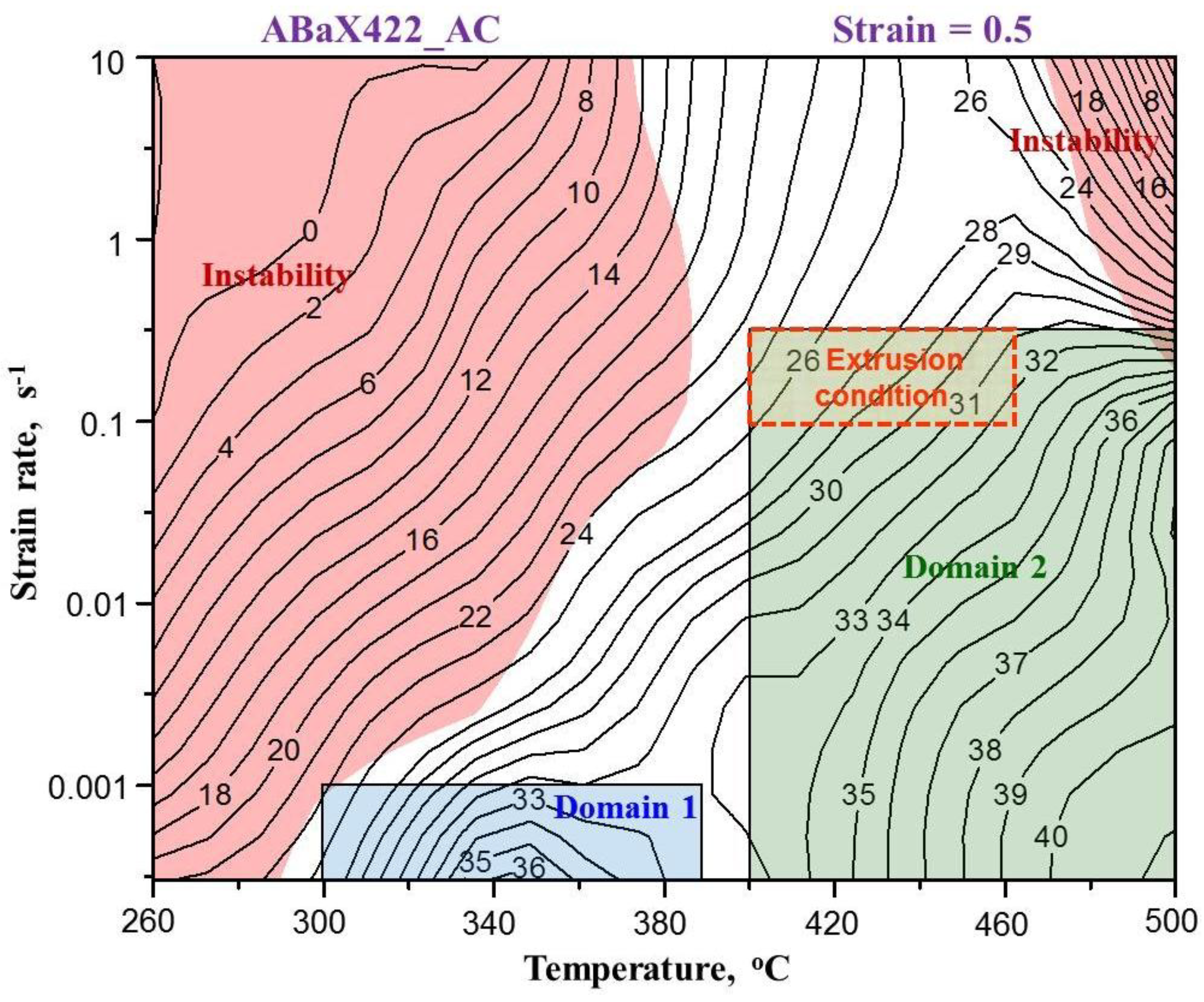
The microstructural response (mechanisms) to hot working of as-cast ABaX422 has been characterized using processing map, which is shown in Figure 3. The numbers associated with the contours represent efficiency of power dissipation (Equation (2)) in percent.
The map exhibits two domains in the temperature and strain rate ranges as follows: (1) 300 °C to 390 °C and 0.0003 s−1 to 0.001 s−1, with a peak efficiency of 36% occurring at 340 °C and 0.0003 s−1; and (2) 400 °C to 500 °C and 0.0003 s−1 to 0.3 s−1, with a peak efficiency of 41% occurring at 500 °C and 0.0003 s−1.
On the basis of microstructures recorded on the deformed specimens and detailed kinetic analysis of the temperature and strain rate dependence of flow stress, these two domains have been identified to represent DRX [13,14]. In the first domain, DRX is controlled by the climb of edge dislocations occurring by lattice self-diffusion, while in the second domain, DRX is controlled by the cross-slip of screw dislocations. Although hot working operations may be conducted in either of the domains, the first domain is not suitable, since the strain rates at which it occurs are too low for the manufacturing process to be viable, and if pushed to higher strain rates, the material undergoes unstable flow resulting in defective microstructure. On the other hand, the second domain is wider in terms of temperature and strain rate ranges; the higher temperatures give better workability and the higher strain rates make the operations faster. To improve the workability of the as-cast material and increase the speed of the manufacturing of wrought products, the constitutive response may be changed by carefully converting the microstructure by hot working at the right temperature and strain rate in Domain #2. The preferred process to achieve this for low-workability materials is the extrusion process, since it is done under constrained compression in a container with large strains imposed in a unit operation and with good control of temperature and speed. The design of such an extrusion process is described below.
3.2. Step 2: Design of Extrusion Experiment
It may be mentioned that the high extrusion ratio is preferred for breaking the as-cast structure completely, and the indirect extrusion process reduces the frictional effects to some extent. The two important process variables in extrusion are the ram speed and the billet temperature. For a simple round-to-round extrusion, the mean strain rate is given by [22]:
where indicates mean strain (lnR), R is the extrusion ratio, t is time, v represents ram velocity and Db is the billet diameter. To extrude a bar of 12 mm diameter, the extrusion ratio is 1:84, and for a ram velocity of 1 mm s−1 and a billet diameter of 110 mm, the average strain rate is about 0.25 s−1, which is close to the upper end of the strain rate for Domain #2. The local strain rate from surface to center of the billet may vary within a narrow band. Thus, a ram velocity of 1 mm s−1 is selected for the extrusion.
As regards the selection of extrusion temperature, factors like an increase in temperature, due to deformation heat and friction at the die wall, and temperature loss, due to conduction to the tools, will have to be considered. For frictionless deformation, the temperature of deformation Td may be calculated using the equation [22]:
where is the mean flow stress, is the mean strain (lnR), β is the conversion factor (fraction of deformation converted into heat), represents density, and c represents the specific heat of the work piece. At 400 °C and 0.1 s−1, the flow stress is about 70 MPa, the mean strain for an extrusion ratio of 84 is 4.43, and the density of Mg is 1700 kg m−3, c is equal to 1020 J kg−1 K−1, the conversion factor is about 0.85 for hot working, and the calculated temperature increase is about 150 °C. However, due to slower extrusion speed, about half of this may be conducted away to the tools, keeping the temperature increase to about 75 °C. With the starting billet temperature of about 390 °C, the extrusion temperature will rise to a maximum of about 465 °C. Thus, the temperature range of 400–465 °C for extrusion will keep the process within the limits for Domain #2. The corresponding extrusion window is marked on the processing map given in Figure 3.
3.3. Hot Working Behavior of ABaX422 after Extrusion
The microstructure of the extruded alloy is shown in Figure 4. When compared with the as-cast microstructure (Figure 2), the intermetallic phases got refined and redistributed. The grain size is reduced to about 7.5 µm from 25 µm in the as-cast condition. The overall refinement and reconstitution of microstructure caused by the occurrence of DRX during extrusion has a significant influence on workability in the subsequent step, as discussed below.
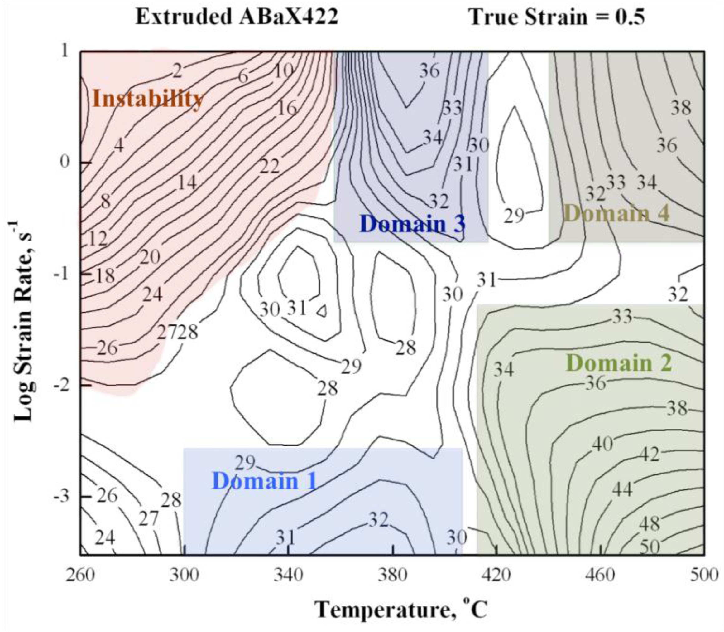
The stress–strain curves obtained at 380 °C and 460 °C and at different strain rates on the extruded ABaX422 alloy is shown in Figure 2, along with the data on the as-cast alloy. The shapes of the curves are very similar for both conditions, although the strength values are generally higher for the as-cast material, particularly at the lower strain rates. The processing map generated for the extruded ABaX422 alloy that corresponds to a true strain of 0.5 is shown in Figure 5.
The numbers on the contours indicate the efficiency of power dissipation in percent. The reddish color area in the Figure 5 corresponds to the regime of flow instability. The processing map exhibits four domains, in the following temperature and strain rate ranges:
Domain 1: 300–400 °C and 0.0003–0.003 s−1, with a peak efficiency of 32% at 380 °C/0.0003 s−1;
Domain 2: 410–500 °C and 0.0003–0.05 s−1, with a peak efficiency of 52% at 500 °C/0.0003 s−1;
Domain 3: 360–420 °C and 0.2–10 s−1, with a peak efficiency of 35% at 380 °C/10 s−1;
Domain 4: 440–500 °C and 0.2– 10 s−1, with a peak efficiency of 40% at 500 °C/10 s−1.
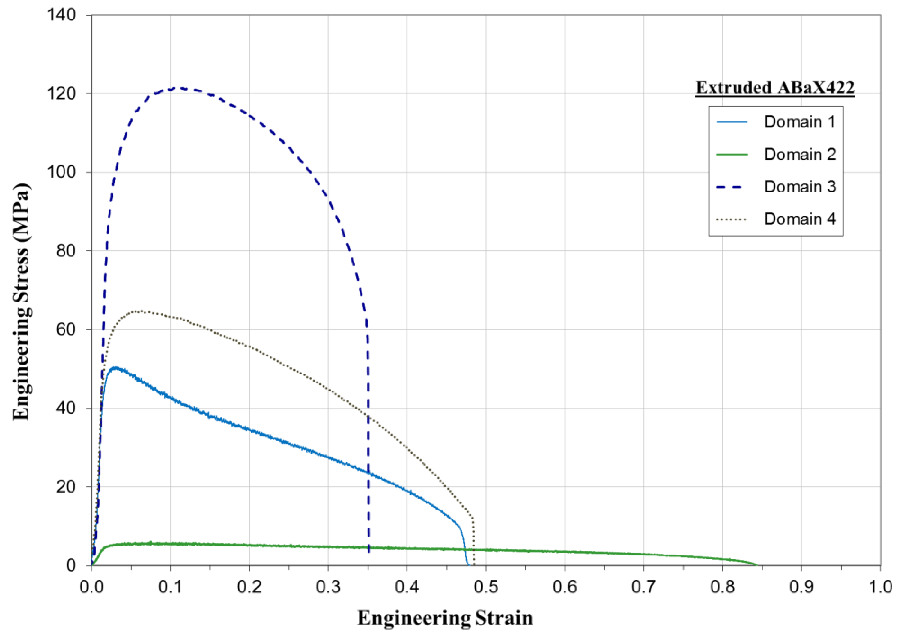
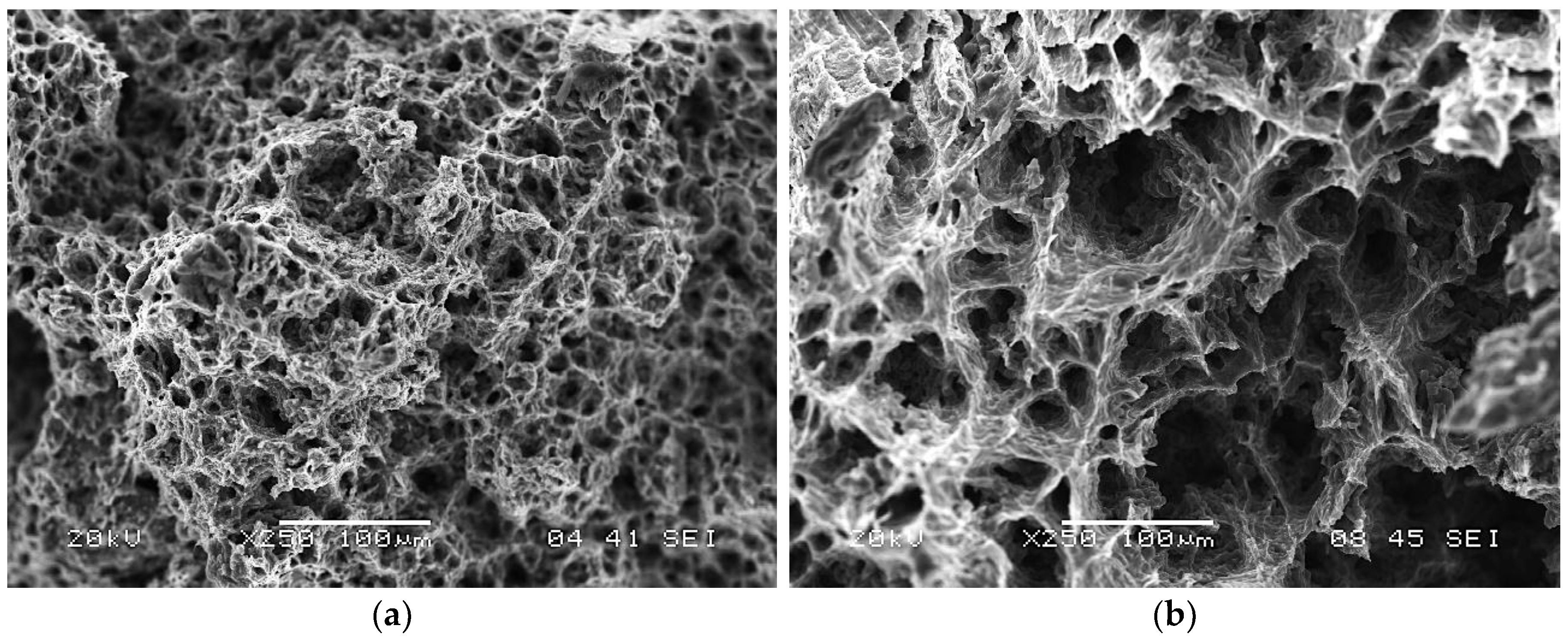
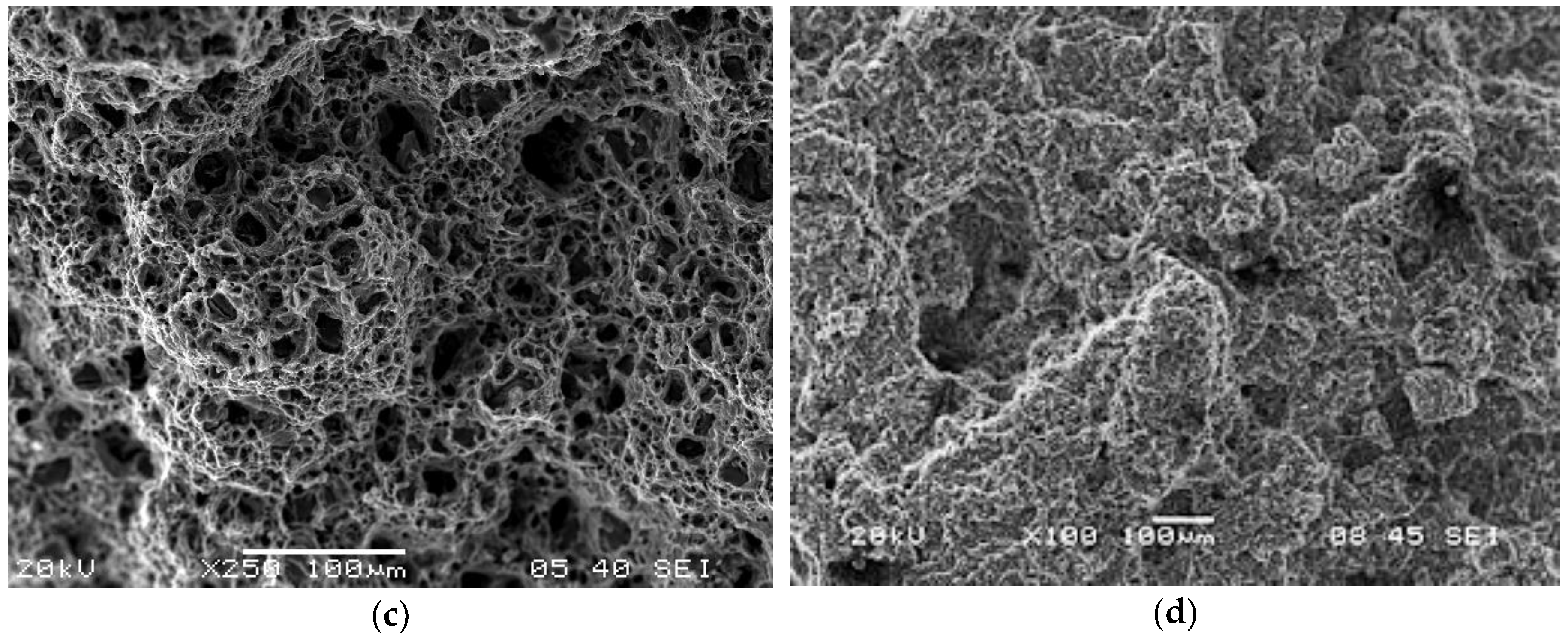
The microstructures obtained for specimens deformed at peak efficiency conditions in the four domains of the processing map are shown in Figure 6. All of them show that DRX has occurred in all the domains. The grain size in the lower temperature domains 1 and 3 is finer than that in the higher temperature domains 2 and 4. The tensile ductility (total elongation) values measured near the peak efficiency conditions are 47% in Domain 1, highest (84%) in Domain 2, 35% in Domain 3, and 48% in Domain 4. Tensile flow curves are shown in Figure 7, and the corresponding mechanical properties are listed in Table 1. The fractographs obtained on the fracture surfaces of the tensile specimens are shown in Figure 8, which indicate that ductile fracture has occurred in Domains 1, 2, and 3, while features of the intercrystalline fracture are seen in Domain 4. Dimple features that can be seen in Figure 8a–c typically indicate ductile fractures.
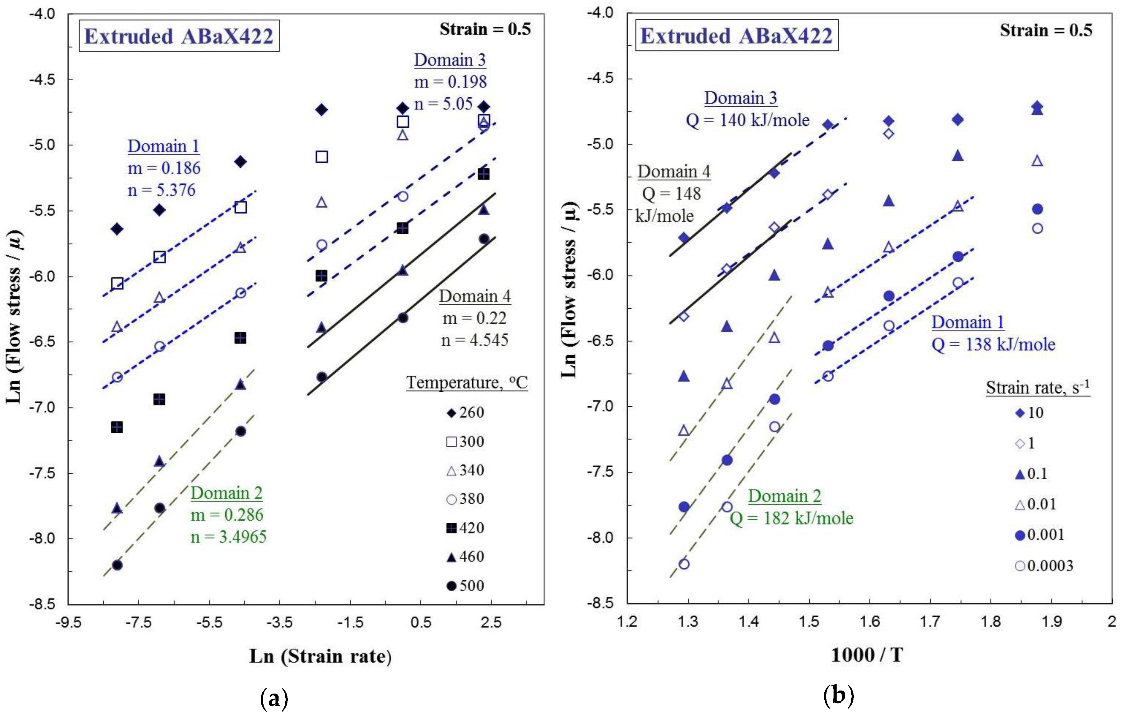
The mechanisms of DRX in Domains 1, 2, and 3 may be further analyzed with the help of kinetic analysis, using a kinetic rate equation that relates the steady-state flow stress (σ) to the temperature (T) and strain rate , given by [23]:
where n, Q, and R are the stress exponent, apparent activation energy, and gas constant, respectively, and A is a constant. Since the rate equation is obeyed within the deterministic domains, the apparent activation energy value can be evaluated for each domain. A plot of flow stress versus strain rate at different temperatures is shown in Figure 9a, and the Arrhenius plot showing the natural logarithm of flow stress normalized with respect to the shear modulus versus the inverse of the absolute temperature is shown in Figure 9b. The values of the activation parameters obtained from these plots are shown in Table 2, for extruded as well as as-cast conditions.
In Domain 1, which occurs in the temperature range of 300–400 °C, a basal slip on {0001} <110> and a prismatic slip {100} <110> occur, and the recovery mechanism that nucleates DRX is climb of edge dislocations, which is controlled by the lattice self-diffusion (LSD). The estimated apparent activation energy (138 kJ/mole) is close to that of lattice self-diffusion in Mg, which is 135 kJ/mole [24]. The slower strain rates at which this domain occurs favors lattice self-diffusion. Thus, DRX in Domain 1 occurs by basal and prismatic slip, along with climb mechanism by lattice self-diffusion.
In Domain 2, which occurs at higher temperatures (410–500 °C), a second-order pyramidal slip {112} <11> occurs. The recovery mechanism nucleating DRX for this system is cross-slip, since a large number of intersecting slip systems are available and the stacking fault energy on these slip planes is considerably high (173 mJ m−2) [25]. The activation energy for this process is higher than that for self-diffusion, due to the particles present in the matrix causing back stress, and the value estimated in this domain (182 kJ/mole) is in support of this. Thus, the mechanism of DRX in Domain 2 involves a second-order pyramidal slip, along with a cross-slip for recovery.
In Domain 3, which occurs at lower temperatures similar to Domain 1, a basal slip {0001} <110> and a prismatic slip {100} <110> occur. The recovery process is a climb of the edge dislocation for these slip systems. However, since this domain occurs at higher strain rates, lattice self-diffusion cannot be a rate-controlling process for the climb, since it is too slow of a process. Alternately, grain boundary self-diffusion may be expected to occur, since it is faster and favored by the finer grain size in the extruded alloy. The apparent activation energy is 140 kJ/mole, which is higher than that required for grain boundary self-diffusion (95 kJ/mole) [24]. The large amount of particle content present in the microstructure causes a high back stress, which increases the apparent activation energy. Thus, the mechanism of the DRX process in Domain 3 is basal and prismatic slip, along with climb controlled by grain boundary self-diffusion.
In Domain 4, the intercrystalline fracture features (Figure 8d) suggest that this domain represents intergranular fracture. Since this domain occurs at higher temperatures, a second-order pyramidal slip {112} <11> occurs. However, the stress concentration at the grain boundaries is not relieved by recovery, since the occurrence of cross-slip is restricted due to high strain rates, resulting in intergranular fracture.
3.4. Hot Working Behavior of As-Cast Versus Extruded ABaX422 Alloy
The differences in the constitutional response of the ABaX422 alloy in as-cast and extruded conditions may be analyzed by comparing the respective processing maps given in Figure 3 and Figure 5. Firstly, Domains 1 and 2 have essentially similar characteristics, including the kinetic parameters given in Table 2. The apparent activation energy is higher for the as-cast alloy, which may be attributed to the back stress generated by the coarse intermetallic phases at the grain boundaries. Secondly, two additional domains have appeared in the map for the extruded alloy. Domain 4 has been identified to represent intercrystalline fracture, and hence is not useful for hot working. However, Domain 3 is worth considering for manufacturing purposes, because it covers faster strain rates (up to 10 s−1); therefore, manufacturing is viable and the product will have a fine-grained microstructure, which is highly desirable.
A careful examination of the two processing maps also reveals that the flow instability regimes are reduced by extruding the material, which gives flexibility in terms of widening the hot working parameters without the onset of instabilities like adiabatic shear banding or flow localization in the product. The presence of these instability manifestations will result in inferior and inconsistent mechanical properties, and should be avoided. Thus, by introducing a hot extrusion step after casting, not only may the material’s workability be improved but also better components may be manufactured faster, making the extrusion a viable process.
3.5. Connected Process Design
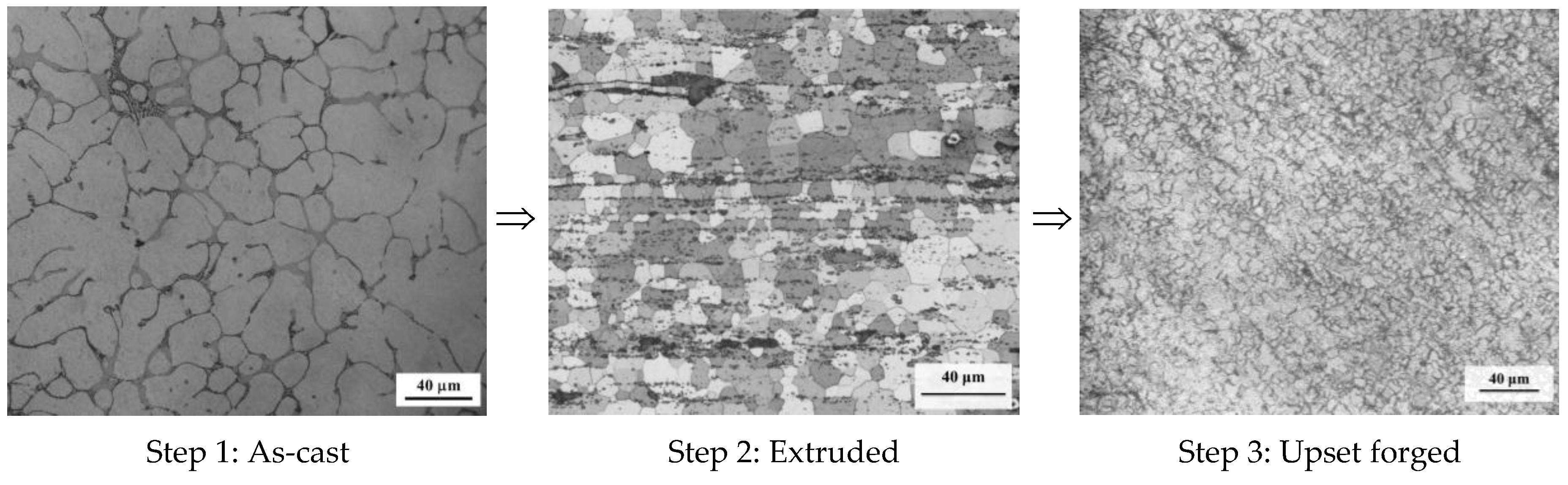
An ABaX422 alloy is used for applications in the automobile industry where creep resistance is a critical requirement. For applications like engine blocks, casting is the primary process. However, for applications where structural integrity and large-scale manufacturing is required, further mechanical working of an as-cast alloy is restricted by its low hot workability and lower speeds of processing. The above results show that by designing a connected step of hot extrusion under controlled conditions, the constitutive response of the alloy may be changed to enhance its workability, mechanical properties, and speed of processing, such that further manufacturing becomes viable. It may be mentioned that a high extrusion ratio is preferred for breaking the as-cast structure completely, and the indirect extrusion process reduces the frictional effects to some extent. The use of high extrusion ratios may result in a smaller diameter or small-size product, but the process may be designed by suitable modification of extrusion equipment, in order to produce the desired sizes. The microstructural changes that are responsible for the change in the material’s response to hot working through this connected process design are summarized in Figure 10, which reveals how the cast structure gets refined in these steps, resulting in better properties in the product. Once the cast structure is transformed into a wrought structure by extrusion (step 2), further hot working by upset forging—for example, at 380 °C and 10 s−1 (step 3)—results in a highly desirable fine-grained microstructure.
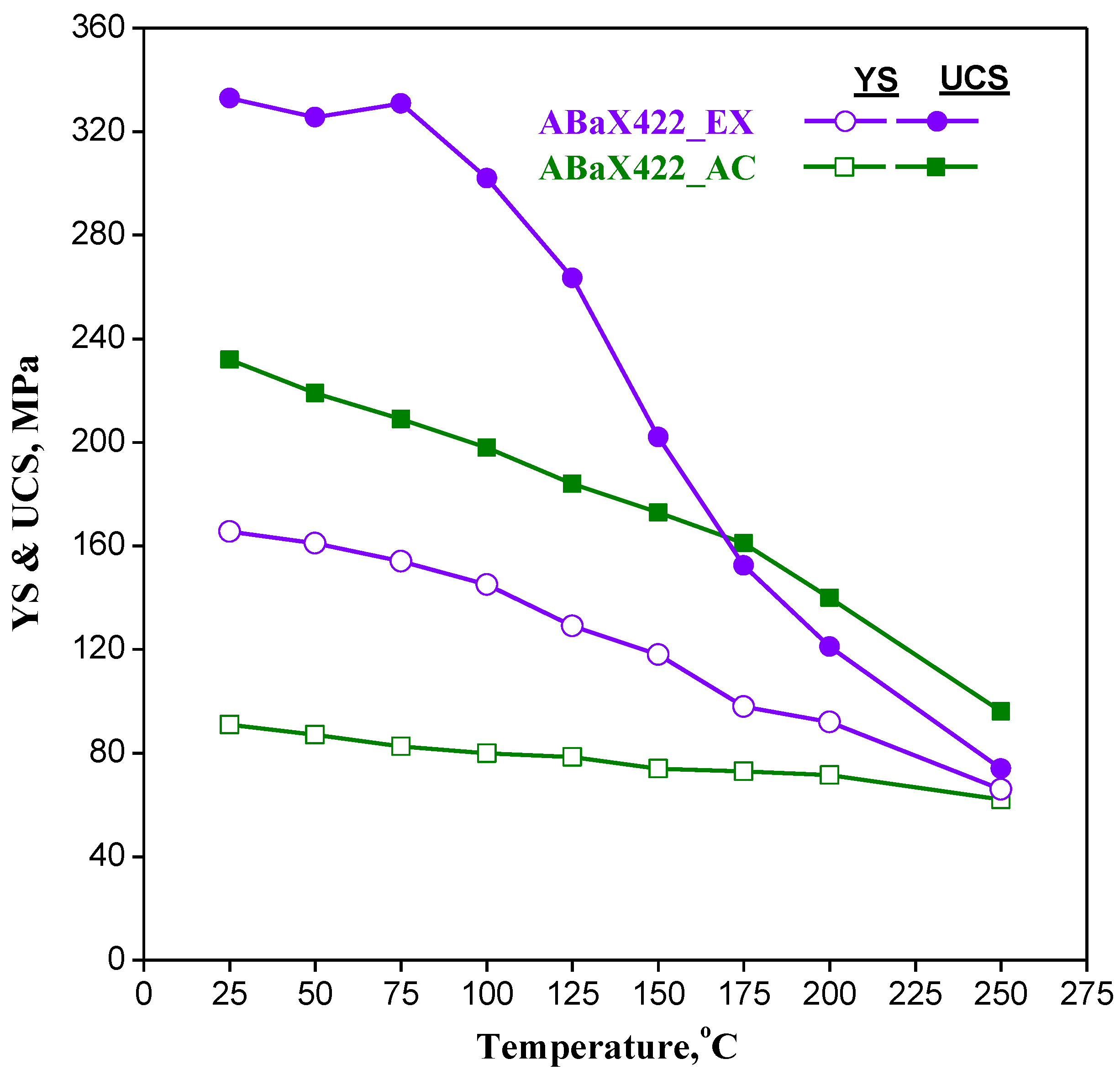
3.6. Compressive Strength of ABaX422 in Temperature Range 25–250 °C
The compressive yield and ultimate strength of the extruded alloy are given in Figure 11 and compared with that for the as-cast alloy. By extruding the alloy, its strength was higher than that of the as-cast alloy up to a temperature of about 175 °C, and the ultimate compressive strength exhibited an improvement of about 42% at room temperature. The enhanced strength property may be attributed to the grain refinement and redistribution of the intermetallic particles caused by the extrusion shown in Figure 4. The generation of crystallographic texture is an additional factor that influences the strength changes, since the as-cast alloy is nearly random, while the extruded rod has a preferred orientation.
4. Conclusions
The constitutive response of the ABaX422 alloy to hot working has been characterized for both as-cast and extruded conditions with the help of processing maps, with a view to design connected processing steps that ensure the viable manufacturing of components. The following conclusions are drawn from this investigation:
- ABaX422 alloy in the as-cast condition has a limited workability, due to a coarse and large-grained microstructure, and cannot be hot worked at higher speeds without causing microstructural damage.
- The processing map for the as-cast ABaX422 alloy offers a window, at temperatures higher than 400 °C and strain rates lower than 0.3 s−1, where the alloy may be hot worked.
- A connected step of extrusion has been designed by selecting a process parameter as per the processing map for the as-cast alloy, and extrusion of a 104 mm diameter billet has been conducted to produce a 12 mm diameter rod product, the microstructure of which has a finer grain size with a redistributed fine particles of the intermetallic phases.
- The processing map for the extruded alloy exhibited four domains—two of them, representing dynamic recrystallization, are similar to those exhibited in the processing map for as-cast material, while the remaining two only appear with the extruded material.
- Out of the two new domains exhibited in the map for the extruded alloy, the one occurring in the temperature range 360–420 °C and strain rate range 0.2–10 s−1 (Domain 3) is useful for manufacturing, since the strain rate is higher, making the process viable, and the temperature is lower, resulting in a finer grain size in the product.
- The fourth domain that occurs at temperatures higher than 440 °C and strain rates higher than 0.2 s−1 represents intercrystalline cracking and causes reduced workability.
- The area of the flow instability regime exhibited in the processing map for the as-cast alloy is reduced by the extrusion step, and this enlarges the workability window.
- Connected process design by changing the constitutive response of hard-to-process alloys may be used to manufacture wrought components at viable speeds and with better mechanical properties.
Author Contributions
K.P.R. and C.D. performed the analysis of the data, generating the processing maps and kinetic analysis, and writing the paper; K.S. performed the experimental work, generating the results and microstructural work; Y.V.R.K.P. contributed to the aspects related to the processing maps and writing the paper; H.D. and N.H. developed and provided the alloys in their initial cast and extruded forms, as well as their microstructures.
Acknowledgments
This work described in this paper was supported by a grant from the Strategic Research Grant (Project #7002744) from the City University of Hong Kong.
Conflicts of Interest
The authors declare no conflict of interest.
References
- Pekguleryuz, M.; Celikin, M. Creep resistance in magnesium alloys. Int. Mater. Rev. 2010, 55, 197–217. [Google Scholar] [CrossRef]
- Powell, B.R.; Rezhets, V.; Balogh, M.P.; Waldo, R.A. Microstructure and creep behavior in AE42 magnesium die-casting alloy. JOM 2002, 54, 34–38. [Google Scholar] [CrossRef]
- Amberger, D.; Eisenlohr, P.; Göken, M. Influence of microstructure on creep strength of MRI 230D Mg alloy. J. Phys. Conf. Ser. 2010, 240, 012068. [Google Scholar] [CrossRef] [Green Version]
- Suzuki, A.; Saddock, N.D.; Riester, L.; Lara-Curzio, E.; Jones, J.W.; Pollock, T.M. Effect of Sr additions on the microstructure and strength of a Mg-Al-Ca ternary alloy. Metall. Mater. Trans. A 2007, 38A, 420–427. [Google Scholar] [CrossRef]
- Rzychon, T.; Chmiela, B. The influence of tin on the microstructure and creep properties of a Mg-5Al-3Ca-0.7Sr-0.2Mn magnesium alloy. Solid State Phenom. 2012, 191, 151–158. [Google Scholar] [CrossRef]
- Hirai, K.; Somekawa, H.; Takigawa, Y.; Higashi, K. Effect of Ca and Sr addition on mechanical properties of a cast AZ91 magnesium alloy at room temperature and elevated temperature. Mater. Sci. Eng. A 2005, 403, 276–280. [Google Scholar] [CrossRef]
- Sato, T.; Kral, M.V. Microstructural evolution of Mg-Al-Ca-Sr alloy during creep. Mater. Sci. Eng. A 2008, 498, 369–376. [Google Scholar] [CrossRef]
- Sadeghi, A.; Pekguleryuz, M. Recrystallization and texture evolution of Mg-3%Al-1%Zn-(0.4-0.8%)Sr alloys. Mater. Sci. Eng. A 2011, 528, 1678–1685. [Google Scholar] [CrossRef]
- Dieringa, H.; Hort, N.; Kainer, K.U. Barium as alloying element for a creep resistant magnesium alloy. In Proceedings of the 8th International Conference on Magnesium Alloys and their Applications, Weinheim, Germany, 26–29 October 2009; Kainer, K.U., Ed.; pp. 62–67. [Google Scholar]
- Dieringa, H.; Huang, Y.; Wittke, P.; Klein, M.; Walther, F.; Dikovits, M.; Poletti, C. Compression-creep response of magnesium alloy DieMag422 containing barium compared with the commercial creep-resistant alloys AE42 and MRI230D. Mater. Sci. Eng. A 2013, 585, 430–438. [Google Scholar] [CrossRef] [Green Version]
- Dieringa, H.; Zander, D.; Gibson, M.A. Creep behaviour under compressive stresses of calcium and barium containing Mg-Al-based die casting alloys. Mater. Sci. Forum 2013, 765, 69–73. [Google Scholar] [CrossRef]
- Rao, K.P.; Suresh, K.; Prasad, Y.V.R.K.; Hort, N.; Dieringa, H. Microstructural Response to Hot Working of Mg-4Al-2Ba-1Ca (ABaX421) as Revealed by Processing Map. In Proceedings of the 10th International Conference on Magnesium Alloys and Their Applications, Jeju, Korea, 11–16 October 2015; pp. 97–104. [Google Scholar]
- Rao, K.P.; Ip, H.Y.; Suresh, K.; Prasad, Y.V.R.K.; Wu, C.M.L.; Hort, N.; Kainer, K.U. Compressive strength and hot deformation mechanisms in as cast Mg-4Al-2Ba-2Ca (ABaX422) alloy. Philos. Mag. 2013, 93, 4364–4377. [Google Scholar] [CrossRef]
- Suresh, K.; Rao, K.P.; Prasad, Y.V.R.K.; Wu, C.-M.L.; Hort, N.; Dieringa, H. Mechanism of dynamic recrystallization and evolution of texture in the hot working domains of the processing map for Mg-4Al-2Ba-2Ca alloy. Metals 2017, 7, 539. [Google Scholar] [CrossRef]
- Rao, K.P.; Dharmendra, C.; Prasad, Y.V.R.K.; Hort, N.; Dieringa, H. Optimization of thermo-mechanical processing for forging of newly developed creep-resistant magnesium alloy ABaX633. Metals 2017, 7, 513. [Google Scholar] [CrossRef]
- Rao, K.P.; Lam, S.W.; Hort, N.; Dieringa, H. High Temperature Deformation Behavior of a Newly Developed Mg Alloy Containing Al, Ba and Ca. In Proceedings of the 7th Thai Society of Mechanical Engineers, International Conference on Mechanical Engineering, Chiang Mai, Thailand, 13–16 December 2016; p. 6, AMM0023. [Google Scholar]
- Prasad, Y.V.R.K.; Seshacharyulu, T. Modelling of hot deformation for microstructural control. Int. Mater. Rev. 1998, 43, 243–258. [Google Scholar] [CrossRef]
- Prasad, Y.V.R.K.; Rao, K.P.; Sasidhara, S. Hot Working Guide: A Compendium of Processing Maps, 2nd ed.; ASM International: Materials Park, OH, USA, 2015; ISBN 978-1-62708-091-0. [Google Scholar]
- Prasad, Y.V.R.K. Processing maps: A status report. J. Mater. Eng. Perform. 2003, 12, 638–645. [Google Scholar] [CrossRef]
- Ziegler, H. Progress in Solid Mechanics; Sneddon, I.N., Hill, R., Eds.; John Wiley: New York, NY, USA, 1965; Volume 4, pp. 91–193. [Google Scholar]
- Prasad, Y.V.R.K.; Rao, K.P. Processing maps and rate controlling mechanisms of hot deformation of electrolytic tough pitch copper in the temperature range 300–950 °C. Mater. Sci. Eng. A 2005, 391, 141–150. [Google Scholar] [CrossRef]
- Dieter, G.E. Mechanical Metallurgy, SI Metric Edition; McGraw Hill Book Co.: London, UK, 1988; p. 628 & p. 525. [Google Scholar]
- Jonas, J.J.; Sellars, C.M.; Tegart, W.M. Strength and structure under hot working conditions. Metall. Rev. 1969, 14, 1–24. [Google Scholar] [CrossRef]
- Frost, H.J.; Ashby, M.F. Deformation-Mechanism Maps; Pergamon Press: Oxford, UK, 1982; p. 44. [Google Scholar]
- Morris, J.R.; Scharff, J.; Ho, K.M.; Turner, D.E.; Ye, Y.Y.; Yoo, M.H. Prediction of a {1122} hcp stacking fault using a modified generalized stacking-fault calculation. Philos. Mag. A 1997, 76, 1065–1077. [Google Scholar] [CrossRef]
Figure 1.
(a) Optical microstructure and (b) SEM micrograph reveals the morphologies of the second phases in the ABaX422 alloy in the as-cast condition.
Figure 1.
(a) Optical microstructure and (b) SEM micrograph reveals the morphologies of the second phases in the ABaX422 alloy in the as-cast condition.

Figure 2.
True stress–true strain curves obtained in compression at (a) 380 °C and (b) 460 °C at different strain rates for the ABaX422 alloy, in both as-cast condition and extruded conditions.
Figure 2.
True stress–true strain curves obtained in compression at (a) 380 °C and (b) 460 °C at different strain rates for the ABaX422 alloy, in both as-cast condition and extruded conditions.
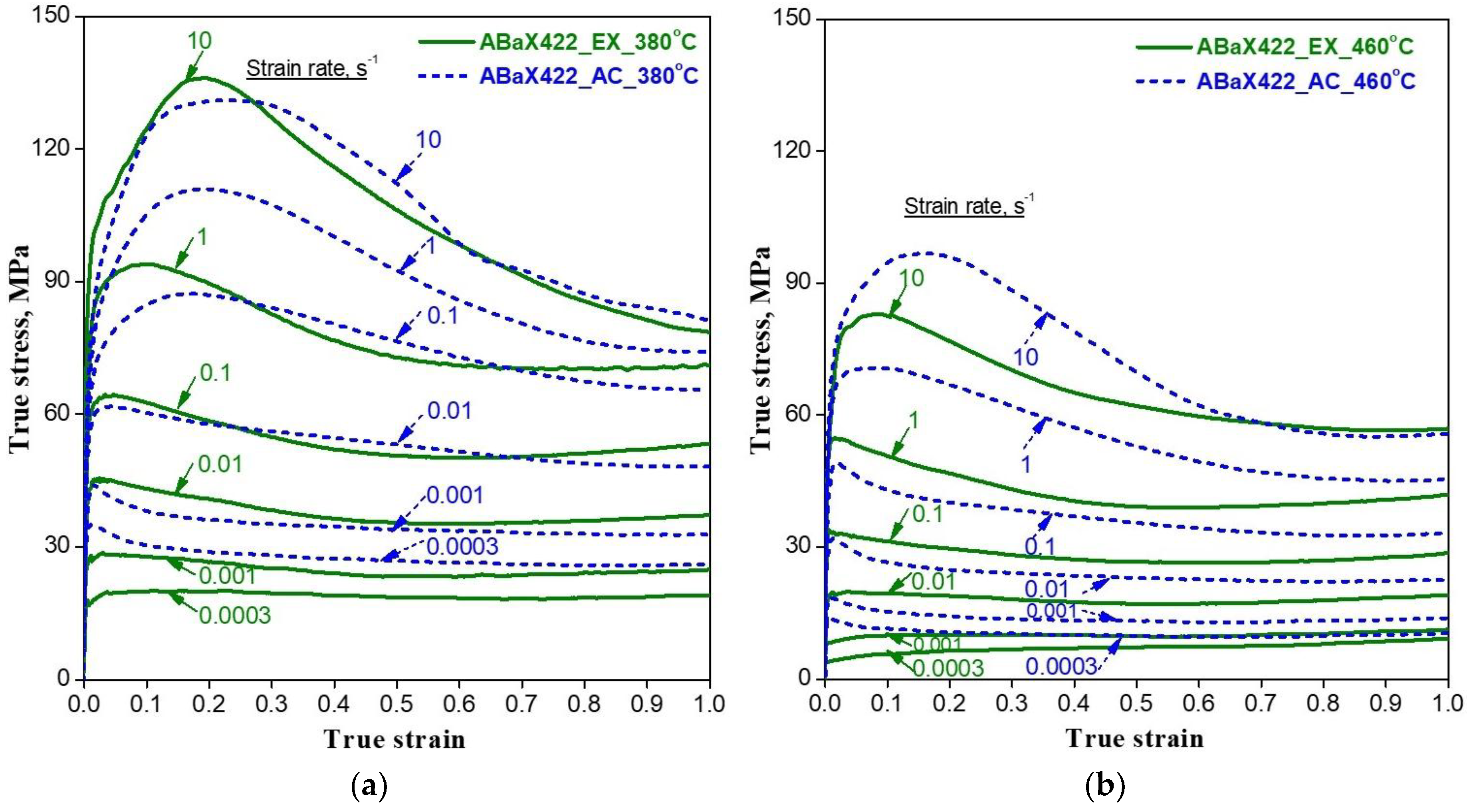
Figure 3.
Processing map for the as-cast Mg–4Al–2Ba–2Ca alloy at a true strain of 0.5. The numbers associated with the contours indicate efficiency of power dissipation in percent, and the instability area is shaded in red. The dotted orange color box indicates the extrusion process condition utilized.

Figure 4.
Optical microstructure of the ABaX422 alloy in the extruded condition. The extrusion direction is horizontal.
Figure 4.
Optical microstructure of the ABaX422 alloy in the extruded condition. The extrusion direction is horizontal.
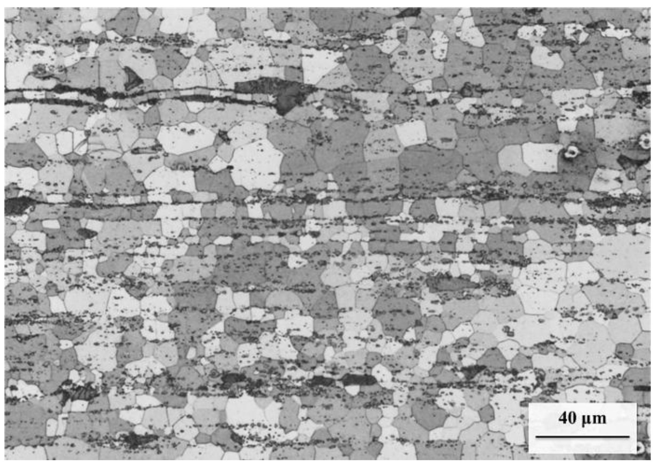
Figure 5.
Processing map for the extruded ABaX422 alloy developed at a true strain of 0.5. The numbers shown with the contours represent dissipation efficiency in percent. The shaded reddish area represents the flow instability regime.
Figure 5.
Processing map for the extruded ABaX422 alloy developed at a true strain of 0.5. The numbers shown with the contours represent dissipation efficiency in percent. The shaded reddish area represents the flow instability regime.

Figure 6.
Microstructures obtained on extruded ABaX422 alloy specimens compressed under peak efficiency conditions in the four different domains of the processing map. (a) Domain 1 (380 °C/0.0003 s−1), (b) Domain 2 (500 °C/0.0003 s−1), (c) Domain 3 (380 °C/10 s−1), and (d) Domain 4 (500 °C/10 s−1).
Figure 6.
Microstructures obtained on extruded ABaX422 alloy specimens compressed under peak efficiency conditions in the four different domains of the processing map. (a) Domain 1 (380 °C/0.0003 s−1), (b) Domain 2 (500 °C/0.0003 s−1), (c) Domain 3 (380 °C/10 s−1), and (d) Domain 4 (500 °C/10 s−1).

Figure 7.
Tensile flow curves for the specimens deformed in the four domains of the processing maps: Domain 1 (380 °C/0.0003 s−1), Domain 2 (500 °C/0.0003 s−1), Domain 3 (380 °C/2.3 s−1), and Domain 4 (500 °C/2.3 s−1).
Figure 7.
Tensile flow curves for the specimens deformed in the four domains of the processing maps: Domain 1 (380 °C/0.0003 s−1), Domain 2 (500 °C/0.0003 s−1), Domain 3 (380 °C/2.3 s−1), and Domain 4 (500 °C/2.3 s−1).

Figure 8.
SEM fractographs of tensile specimens deformed in the four domains of the processing maps: (a) Domain 1 (380 °C/0.0003 s−1; total elongation: 47%), (b) Domain 2 (500 °C/0.0003 s−1, total elongation: 84%, (c) Domain 3 (380 °C/2.3 s−1; Total elongation: 35%), and (d) Domain 4 (total elongation: 48%).


Figure 9.
(a) Variation of normalized flow stress with strain rate on natural logarithmic scale, and (b) an Arrhenius plot of normalized flow stress with the inverse of absolute temperature. The apparent activation parameters n and Q are estimated with data relevant to various domains of the processing map for the extruded ABaX422 alloy.

Figure 10.
Microstructural changes in continued processing steps of the ABaX422 magnesium alloy.

Figure 11.
Compressive yield and ultimate compressive strength of the ABaX422 alloy in the as-cast and extruded conditions.
Figure 11.
Compressive yield and ultimate compressive strength of the ABaX422 alloy in the as-cast and extruded conditions.

Table 1.
The tensile mechanical properties of the specimens that correspond to the four domains in the processing maps of the extruded ABaX422 alloy.
Table 1.
The tensile mechanical properties of the specimens that correspond to the four domains in the processing maps of the extruded ABaX422 alloy.
| Condition | Yield Strength (MPa) | Ultimate Tensile Strength (UTS), MPa | Strain to Fracture | Maximum Displacement (mm) | % Elongation |
|---|---|---|---|---|---|
| Domain 1 (380 °C and 0.0003 s−1) | 41 | 50 | 0.47 | 19.25 | 47% |
| Domain 2 (500 °C and 0.0003 s−1) | 2 | 6 | 0.82 | 32.89 | 84% |
| Domain 3 (380 °C/2.3 s−1) | 80 | 121 | 0.35 | 17.61 | 35% |
| Domain 4 (500 °C/2.3 s−1) | 50 | 64 | 0.49 | 19.64 | 48% |
Table 2.
The kinetic parameters, namely the stress exponent (n) and apparent activation energy (Q), in the various domains of the processing maps for the ABaX422 alloy, and the proposed rate-controlling mechanisms in the as-cast and extruded conditions.
Table 2.
The kinetic parameters, namely the stress exponent (n) and apparent activation energy (Q), in the various domains of the processing maps for the ABaX422 alloy, and the proposed rate-controlling mechanisms in the as-cast and extruded conditions.
| Domain # | As-Cast (Ref. [13]) | Extruded | ||||
|---|---|---|---|---|---|---|
| n | Q (kJ/mole) | Mechanism | n | Q (kJ/mole) | Mechanism | |
| 1 | 5.24 | 169 | Climb (LSD) | 5.37 | 138 | Climb (LSD) |
| 2 | 4.46 | 263 | Cross-slip | 3.49 | 182 | Cross-slip |
| 3 | - | - | - | 5.05 | 140 | Climb (GSD) |
| 4 | - | - | - | 4.54 | 148 | GB cracking |
Note: LSD: Lattice self-diffusion; GSD: Grain boundary self-diffusion; GB: grain boundary.
© 2018 by the authors. Licensee MDPI, Basel, Switzerland. This article is an open access article distributed under the terms and conditions of the Creative Commons Attribution (CC BY) license (http://creativecommons.org/licenses/by/4.0/).
Share and Cite
MDPI and ACS Style
Rao, K.P.; Chalasani, D.; Suresh, K.; Prasad, Y.V.R.K.; Dieringa, H.; Hort, N. Connected Process Design for Hot Working of a Creep-Resistant Mg–4Al–2Ba–2Ca Alloy (ABaX422). Metals 2018, 8, 463. https://doi.org/10.3390/met8060463
AMA Style
Rao KP, Chalasani D, Suresh K, Prasad YVRK, Dieringa H, Hort N. Connected Process Design for Hot Working of a Creep-Resistant Mg–4Al–2Ba–2Ca Alloy (ABaX422). Metals. 2018; 8(6):463. https://doi.org/10.3390/met8060463
Chicago/Turabian StyleRao, Kamineni Pitcheswara, Dharmendra Chalasani, Kalidass Suresh, Yellapregada Venkata Rama Krishna Prasad, Hajo Dieringa, and Norbert Hort. 2018. "Connected Process Design for Hot Working of a Creep-Resistant Mg–4Al–2Ba–2Ca Alloy (ABaX422)" Metals 8, no. 6: 463. https://doi.org/10.3390/met8060463
Note that from the first issue of 2016, this journal uses article numbers instead of page numbers. See further details here.