Article

Production of Clean Steel Using the Nitrogen Elevating and Reducing Method

1
Engineering Research Institute, University of Science and Technology Beijing, No.30 Xueyuan Road, Haidian District, Beijing 100083, China
2
HBIS Group SHISTEEL Company, No. 363, Hepingdong Road, Shijiazhuang 050031, China
*
Author to whom correspondence should be addressed.
Metals 2018, 8(7), 560; https://doi.org/10.3390/met8070560
Submission received: 27 June 2018 / Revised: 16 July 2018 / Accepted: 16 July 2018 / Published: 21 July 2018
(This article belongs to the Special Issue 5th UK-China Steel Research Forum)

Abstract

:
Nitrogen Elevating and Reducing Method (NERM) is a new technology developed to remove inclusions and oxygen in molten steel. The principle that underlies it is that nitrogenizing molten steel under low or normal pressure initially elevates the nitrogen content. Then, when the vacuum treatment is started, the nitrogen bubbles can nucleate on the surface of the inclusions and carry them to slag, reducing the number of inclusions in steel significantly. The removal effects between the new method and the conventional method were compared by industrial trials in this paper. The results show that the average oxygen content of the billet produced by the conventional method was 16 ppm, while that produced by the new method dropped to 11.5 ppm. Besides, the new method shows better removal effect of inclusions, and the number of inclusions decreased by 52.8% compared to the conventional method. The new method has obvious removal effects on inclusions in different sizes. In addition, the differences between NERM and the Pressure Elevating and Reducing Method (PERM) were compared, and the mechanism of each method was analyzed in this paper.

1. Introduction

Non-metallic inclusion has a strong influence on the quality and performance of steels [1,2,3,4,5]. The technologies of inclusion removal mainly include the slag washing method [6], the inclusion filtration method, the ladle electromagnetic stirring method [7], the tundish centrifugation method [8,9], the crystallizer electromagnetic brake method [10], and several gas refining methods [11,12,13,14,15,16,17,18], etc. Some gas refining methods have been widely used, because there is no need to retrofit the equipment. The cost is low, and the removal effect of inclusions is good. The mechanism of inclusion removal using the conventional methods is that the inclusions are adhered by bubbles as the bubbles float up to the top of molten steel. A mathematical model has been developed to determine the optimum bubble size for the removal of inclusions from molten steel by flotation [19]. Calculation results show that smaller bubbles have a better removal effect of inclusions. Therefore, generating a large number of dispersed micro-bubbles in molten steel is the key to inclusion removal by bubbles adhesion. Some methods, such as ladle argon blowing, which injects gas into molten steel directly, have been used in the production of clean steels. However, due to the size of bubbles generated by the tuyere, spray gun and perforated brick is large (the diameter is 10–20 mm generally [20,21,22]), and the collision probability between bubbles and inclusions is low. This leads to a limited removal effect of inclusions, especially for the inclusions that are smaller than 50 μm [23].
Unlike the mechanism of the conventional gas refining methods, the principle of the Pressure Elevating and Reducing Method (PERM) [16] is that the nitrogen gas is forcibly dissolved into the molten steel at first by the pressurization treatment, and the nitrogen content of the molten steel increases significantly. Then, when the vacuum treatment is started, nitrogen bubbles can nucleate on the surface of the inclusions and carry them to the slag. The bubbles can also adhere to the inclusions during the floatation process, which can remove the inclusions in steel effectively. However, this method needs to seal and pressurize the molten steel in the nitrogen addition process, which places a high requirement on the equipment, and this limits the application range. The Nitrogen Elevating and Reducing Method (NERM) is a new technique developed for the removal of inclusions in steel [18]. When using this method, nitrogen gas is added to the molten steel under normal or low pressure, and the initial nitrogen content of the molten steel is low. Then, like the PERM, the nitrogen bubbles can nucleate on the surface of the inclusions and carry them to the slag during the vacuum treatment. This method has the advantage that there is no need for pressurization treatment of molten steel, the requirement on equipment is low, and the effect of inclusion removal is great. The experiment results carried out by 10 Kg vacuum induction furnace (VIF) using NERM [18] show that the initial nitrogen content of bearing steel is about 100–400 ppm after the nitrogen addition process. The number of inclusions in the steel significantly decreased, and the oxygen content in the steel also decreased significantly after vacuum treatment.
Although NERM has achieved great results in laboratory experiments, the effect of this method in actual production and the mechanism of this method have not been sufficiently researched. Based on this, the experiment was conducted at HBIS Group SHISteel Corporation (Heibei province, China) based on the BOF-LF-VD-CC process. The refining effects of NERM and the conventional method (Ar bottom-blowing method) were compared. In addition, the differences between NERM and PERM were compared, and the mechanism of each method was analyzed in this paper.

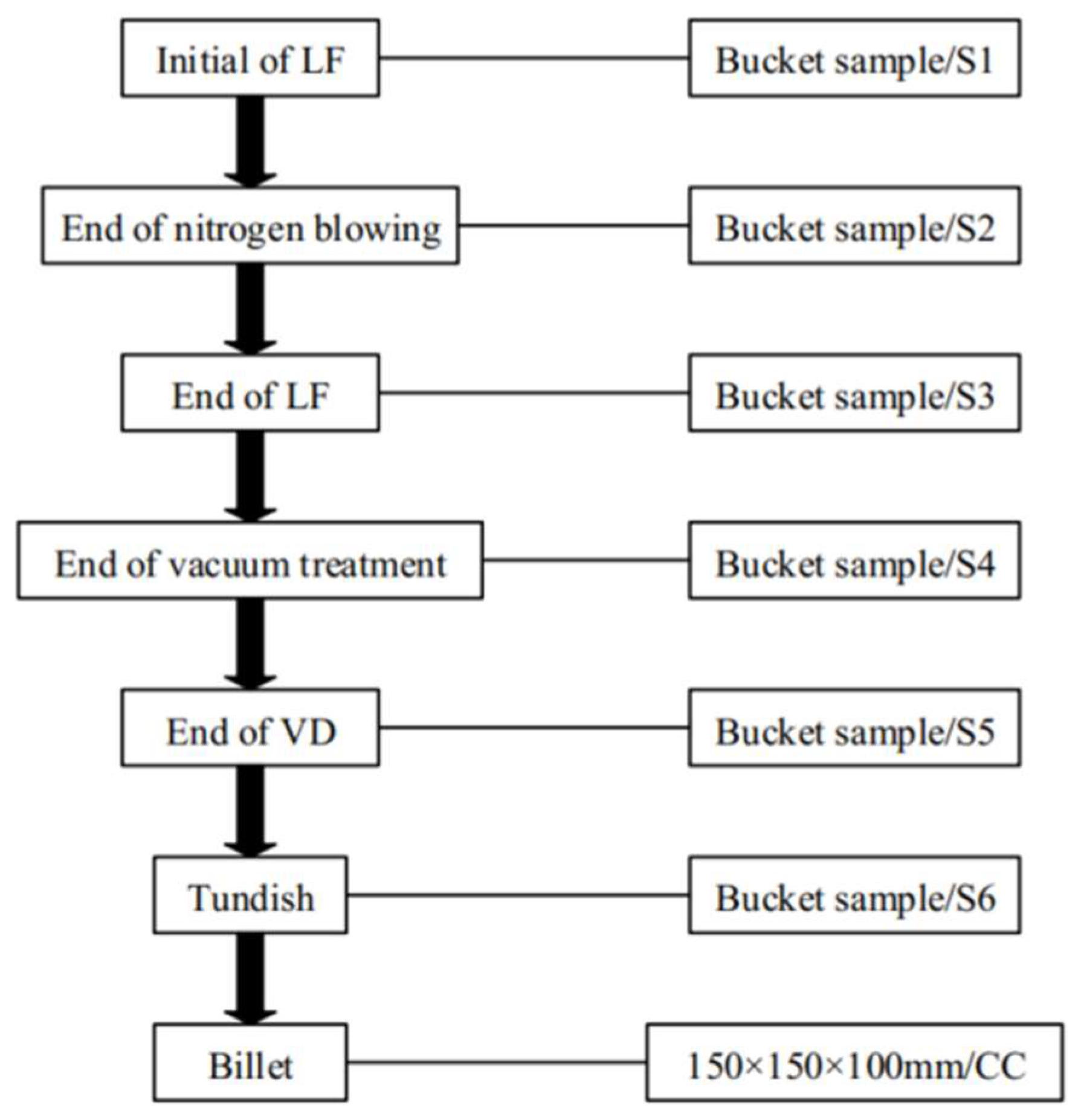
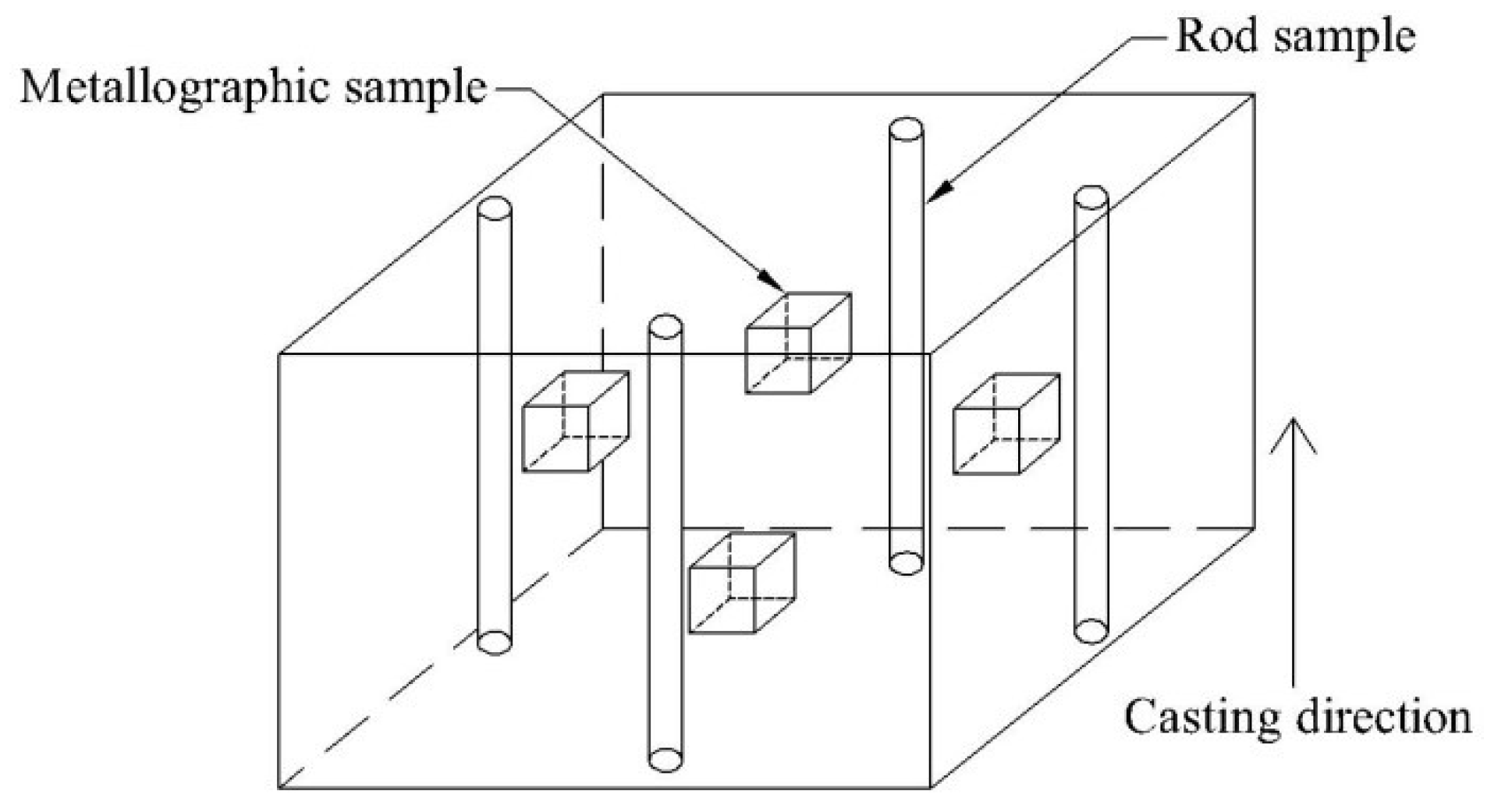
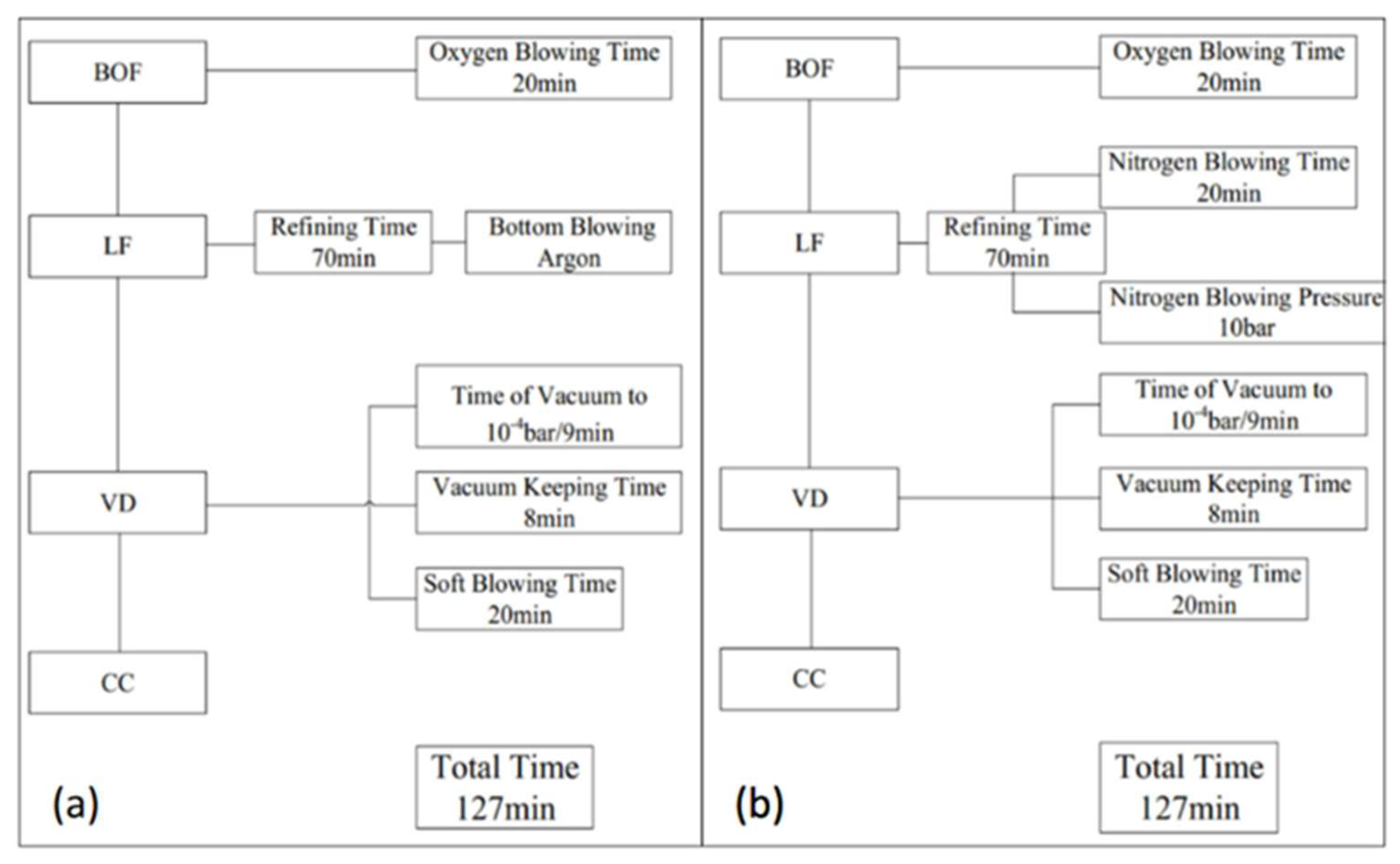
2. Industrial Experiments

The industrial trial was conducted at HBIS SHISteel Corporation. The process was as follows: basic oxygen furnace (BOF) → ladle furnace (LF) → vacuum degassing (VD) → continuous casting (CC). The steel making process was carried out in a 60t ladle, and the size of the ladle is (Φ2347 mm—inner diameter of top, Φ2049 mm—inner diameter of bottom) × H2960 mm. The experimental steel is 20CrMo Al-killed steel, and the main components of this steel are shown in Table 1.
The composition of refining slag in each process did not change much, and the main components of the slag are shown in Table 2.
The experimental processes of NERM and conventional method are shown in Figure 1. The operation of the experiment was as follows: (1) After the BOF process, the molten steel was refined in LF for 70 min. In the LF process, after a period of argon bottom blowing, the gas was switched to nitrogen, and nitrogen was blown into molten steel for 20 min using the NERM. However, argon was blown into the molten steel during the entire refining process using conventional method. The flow rate of bottom blowing was about 300 L/min. The flow rate was adjusted according to the production conditions. The pressure of nozzle was 10 bar. The tapping temperature of LF was about 1640 °C. (2) After LF refining, the ladle was transferred to VD for vacuum treatment. After vacuum treatment for 9 min, the vacuum degree of the ladle reached to 10−4 bar. The vacuum atmosphere was maintained for 8 min. In the vacuum treatment, argon gas was blown into the molten steel from the bottom with a low flow rate. Then, blowing by argon gas was started and lasted for 20 min. For each method, the same treatment was conducted in the VD process. (3) Finally, the billet with cross-sectional dimension of 150 mm × 150 mm was produced by continuous casting. It can be concluded that the process time for each method was 127 min, which means using NERM will not increase the smelting time.
In order to analyze the samples accurately and avoid the contingency of the experiment, two groups of repeated experiments were conducted for each method. The two heats with NERM were numbered No. 1 and No. 2, respectively. The two heats with conventional method were numbered No. 3 and No. 4, respectively. Samples were collected from each process of LF-VD-tundish using bucket samplers. The dimension of the bucket sampler is Φ30 mm × 50 mm. Rod samples (Φ5 mm × 40 mm) were cut from the bucket samplers to analyze the change of nitrogen content in the molten steel in each process. Because argon gas was blown through the entire LF refining process using the conventional method, the nitrogen content of molten steel changed little. Thus, start sampling from the end of LF using conventional method. From the initial of LF to the tundish, the samples were numbered from S1 to S6, respectively. The billet was numbered CC. The number of samples in each process is shown in Figure 2.
A section was cut from the billets, and the size is 150 × 150 × 100 mm. In order to measure the number of inclusions and oxygen/nitrogen content in the billets accurately, four metallographic samples (10 × 10 × 10 mm) and four rod samples (Φ30 mm × 50 mm) were cut from the billet near the inner&outer arc and the two surfaces of the width direction, as shown in Figure 3. The scanning electron microscope (SEM, Carl Zeiss AG, Oberkochen, Germany) was used to record the size and morphology of inclusions. The compositions of inclusions were measured by X-ray energy dispersive spectrometry (EDS, Oxford Instruments, Oxford, The Great Britain). An automated program called “INCA Feature” [24] was used to analyze the number and type of inclusions in billets. 50 view fields of each metallographic sample were randomly selected, and the magnification is 500 times. The oxygen/nitrogen contents of the rod samples were measured, and the average value was defined as the oxygen/nitrogen contents of the billets.

3. Results

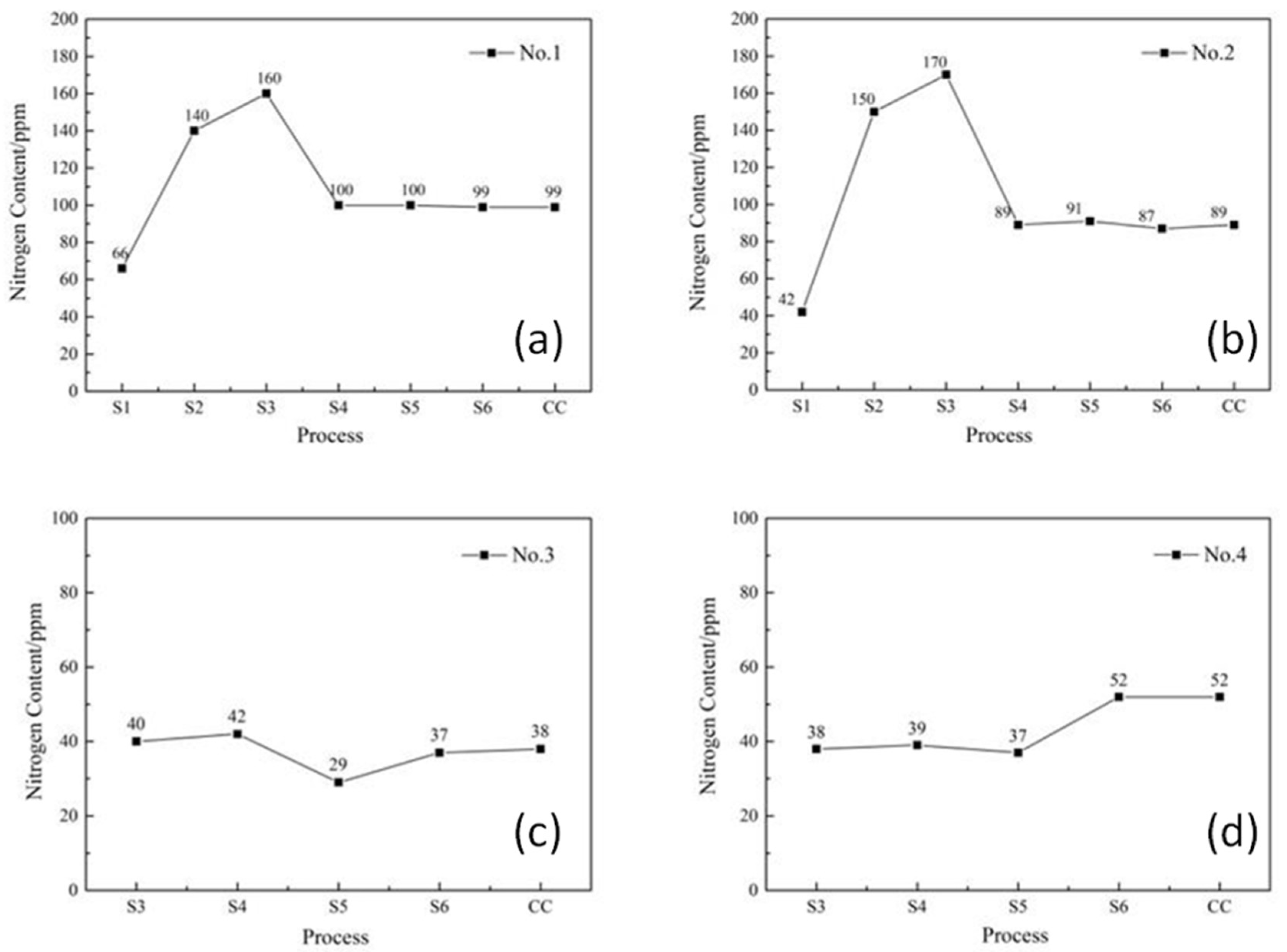
3.1. Changes of Nitrogen/Oxygen Content in Steel

Figure 4 shows the nitrogen contents of the steel in each process. After nitrogen addition process, the nitrogen contents of No.1 and No.2 heat obviously increased from 66 ppm and 42 ppm to 140 ppm and 150 ppm. At the end of the LF process, the nitrogen contents further increased to 160 ppm and 170 ppm; after vacuum treatment, the nitrogen contents dropped to 100 ppm and 89 ppm and changed little in the subsequent processes. As a result, the nitrogen contents in billet of No. 1 and No. 2 heats were 99 ppm and 89 ppm, respectively.
The change of nitrogen contents of No. 3 and No. 4 heats was small in each process. The nitrogen contents at the end of LF were 40 ppm and 38 ppm, respectively. In the subsequent processes, the nitrogen contents varied in the range of 10 ppm, and the nitrogen content in billets of the No. 3 and No. 4 heats was 38 ppm and 52 ppm, respectively. Although the nitrogen contents in the billet using NERM is about 40 ppm higher than that of the conventional method, the billets produced by each method still met the production requirement.
Figure 5 shows the oxygen contents of the billets. The oxygen contents in billets of No. 1 and No. 2 heats were 10 ppm and 11 ppm, respectively, while the oxygen contents in billets of No. 3 and No. 4 heats were 15 ppm and 17 ppm, respectively. The average oxygen content of the billets decreased by 34.38% using NERM compared with the conventional method.

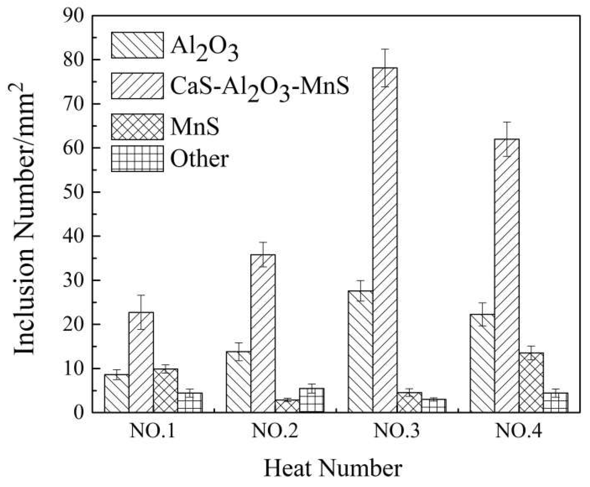
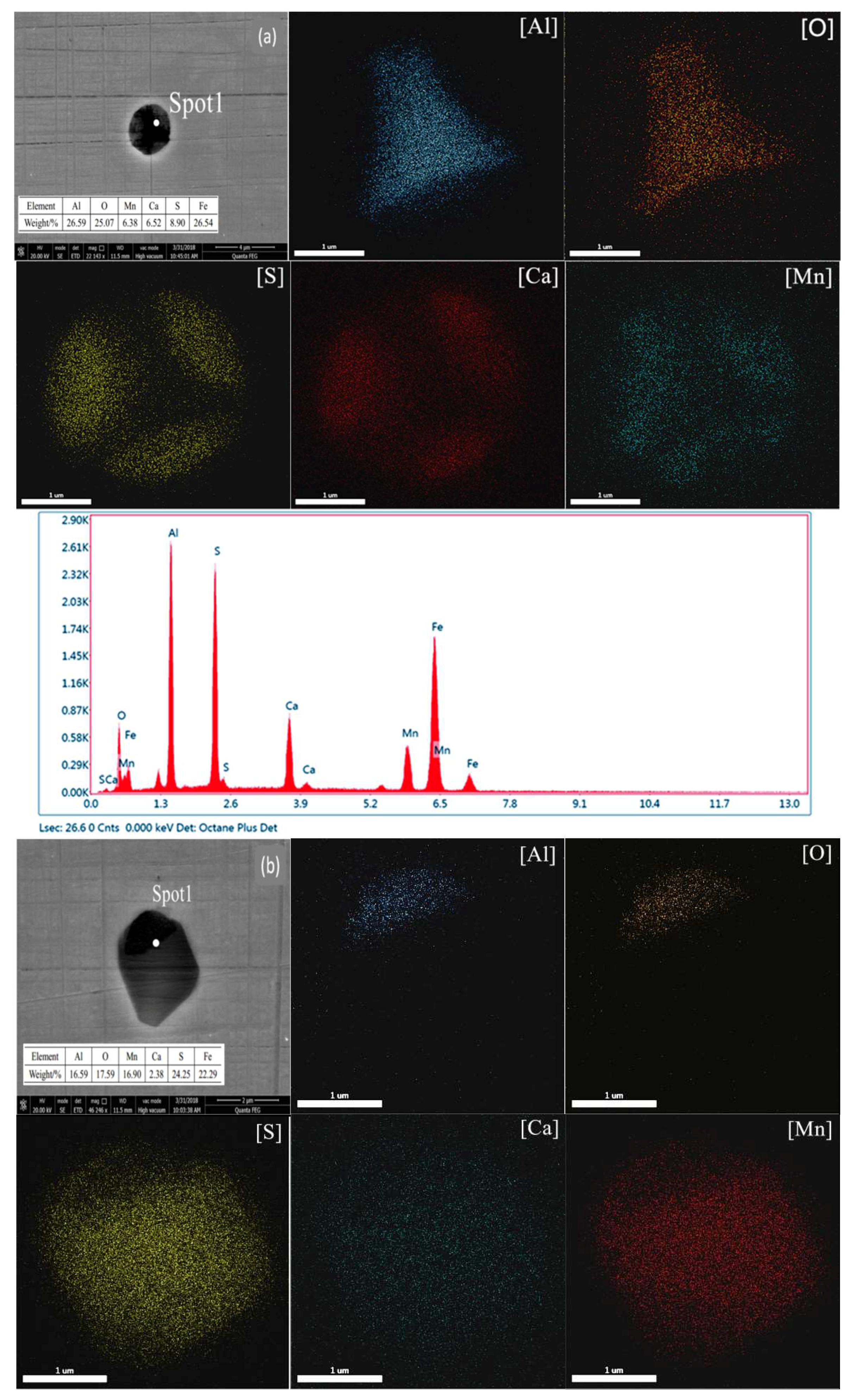
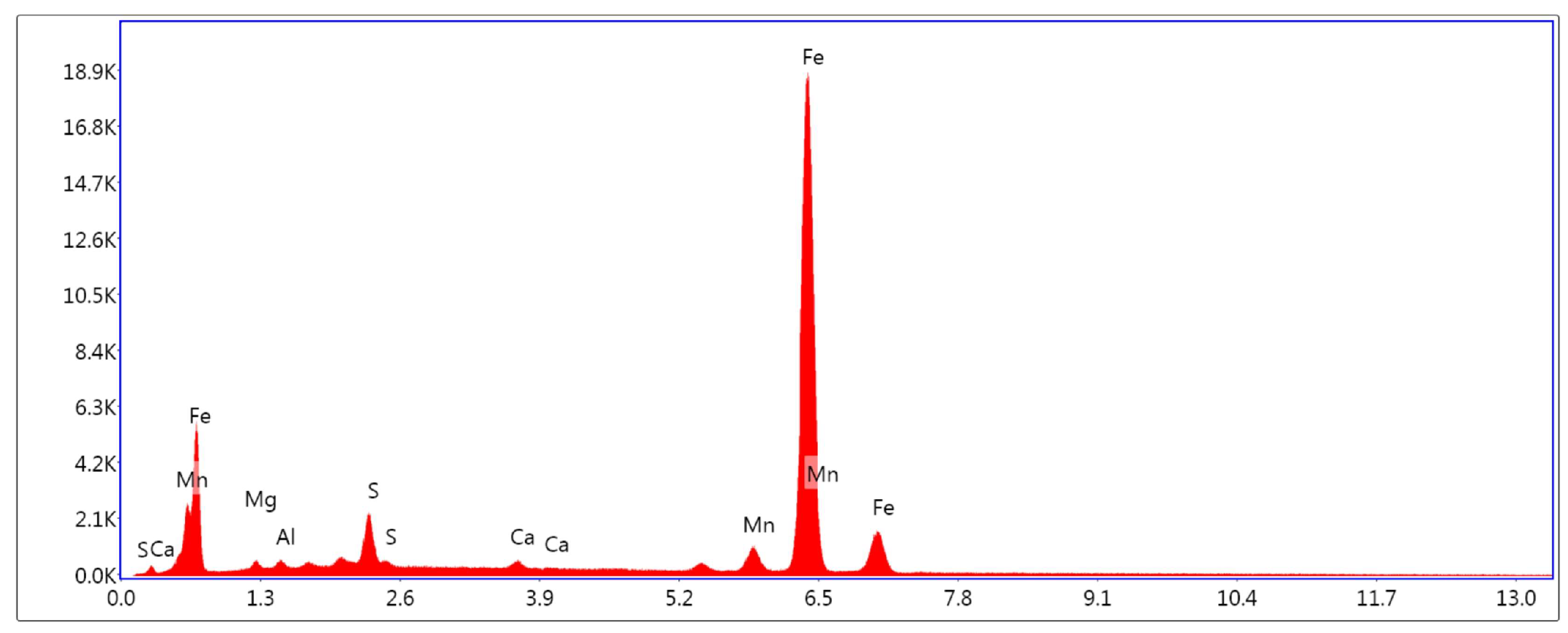
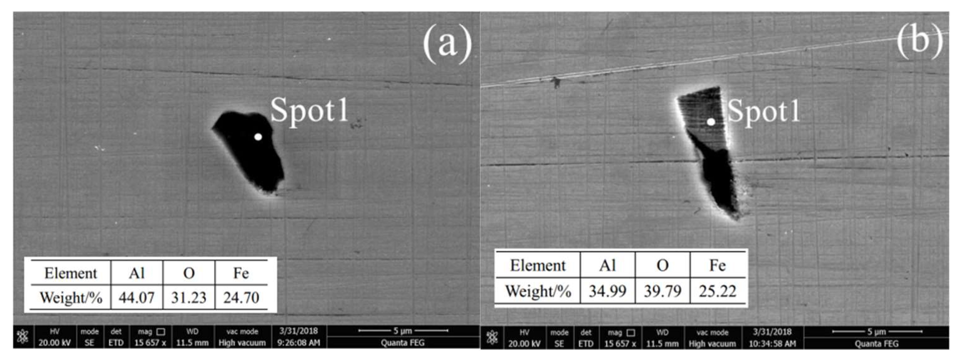
3.2. The Type and Morphology of Inclusions in Billets

The number of the different types of inclusions in billets was shown in Figure 6. It can be concluded from the figure that the inclusions in billets are mainly CaS-MnS-Al2O3 inclusions and Al2O3 inclusions. Besides, there are some MnS inclusions and a small amount of SiO2 and CaO inclusions. The proportions of the different types of inclusions change little. It can be seen from the figure the number densities of inclusions in No. 1 and No. 2 heats is significantly lower than those in No. 3 and No. 4, and this will be discussed in detail later.
The mapping images of CaS-MnS-Al2O3 inclusions were shown in Figure 7. The figure shows that the Al2O3 inclusions could be the cores, and then the CaS and MnS inclusions formed a shell on their surfaces. The shape of the composite inclusions is approximately spherical. Under the conditions of this experiment, the calcium content in molten steel is about 4 ppm, and the sulfur content in molten steel is about 100 ppm at the beginning of VD vacuum treatment. According to the results of a thermodynamic model [25], the formation temperature of CaS is below 1500 °C under the conditions of this study. A thermodynamic model [26] was used to calculate the liquidus temperature and solidus temperature of the experimental steel. The calculation results show that the liquidus temperature is 1526 °C, and the solidus temperature is 1447 °C. Therefore, CaS can be formed during the solidification process.
The standard generation Gibbs free energy of MnS is Δ G M n S Θ = 131624 + 79.07 T [27]. T is the temperature of the steel. Before the molten steel is completely solidified, generation Gibbs free energy of MnS is Δ G M n S = 92360 kJ mol 1 > 0 . This means that MnS can only be formed after solidification process. After deoxidation, the main inclusions were Al2O3 inclusions in molten steel. Thus, CaS and MnS could nucleate on the surface of Al2O3 inclusions, and CaS-MnS-Al2O3 composite inclusions can be formed eventually during the solidification process.
It can be drawn from the analysis results above that the main inclusions in molten steel were Al2O3 inclusions that account for more than 70% of the total number of inclusions. The morphology of Al2O3 inclusions was shown in Figure 8. It can be seen from the figure that the shape of Al2O3 inclusions in billets are irregular or triangular mostly. The previous studies have proved [28] that bubbles could nucleate on the surface of Al2O3 inclusions in vacuum process. So, using NERM can remove inclusions in this steel in theory.

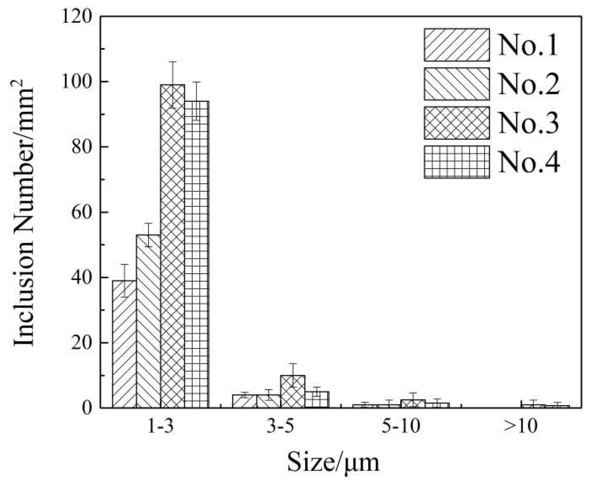
3.3. Effect of Inclusion Removal

Figure 9 shows the quantity of inclusions per scanning area (mm2) in each billet that was obtained by using INCAFeatue. A total of 200 view fields (7.68 mm2) of four metallographic samples cut from each billet were observed.
It can be concluded from Figure 9 that the number densities of inclusions in the billets of No. 1 and No. 2 were 43/mm2 and 58/mm2, respectively. After NERM treatment, the average number density of inclusions in the billet was 50.5/mm2. The number densities of inclusions in the billets of No. 3 and No. 4 were 113/mm2 and 101/mm2, respectively. After the conventional method treatment, the average number density of inclusions in the billets was 107/mm2. The new method shows a better removal effect of inclusions, and the number density of inclusions decreased by 52.8% compared to conventional method.
In addition, it can be seen from Figure 9 that after using the NERM treatment, the number densities of inclusions with all size ranges was reduced, especially the inclusions with the size of 1–3 μm, which implies that NERM has a significant effect on the removal of micro inclusions in steel compared to conventional method. Furthermore, the inclusions larger than 10 μm were completely removed, which means the new method is thorough in the removal of large inclusions.

4. Discussion

The experimental results have proved that the NERM method has a better inclusion removal effect than conventional method. However, in many gas refining methods, the Pressure Elevating and Reducing Method (PERM) also has obvious removal effect on the micro inclusions and oxygen content in steel [16]. After the refining process of PERM, the average oxygen content in the billets of stainless steel decreased from 33.8 ppm to 25.1 ppm, and the average oxygen content decreased by 25.74% compared to the conventional method.
PERM and NERM both have obvious removal effect on inclusions in steel and similar smelting processes. However, PERM need to pressurize the ladle system during the nitrogen addition process, and nitrogen is forcibly dissolved into the molten steel, which results in high initial nitrogen contents of the molten steel. The nitrogen content could reach about 1400 ppm in the experiment using stainless steel. However, there is no pressurization process in NERM. The molten steel is treated under normal or lower pressures during the nitrogen addition process. The initial nitrogen content of the molten steel is much lower compared to PERM. Since the amount of nitrogen dissolved in molten steel will directly affect the depth range of bubble nucleation and nucleation rate, the effects of nitrogen content on the bubble nucleation were analyzed from different perspectives in this paper. Based on this, the difference in the mechanisms of inclusion removal of the two methods were analyzed and compared in detail.

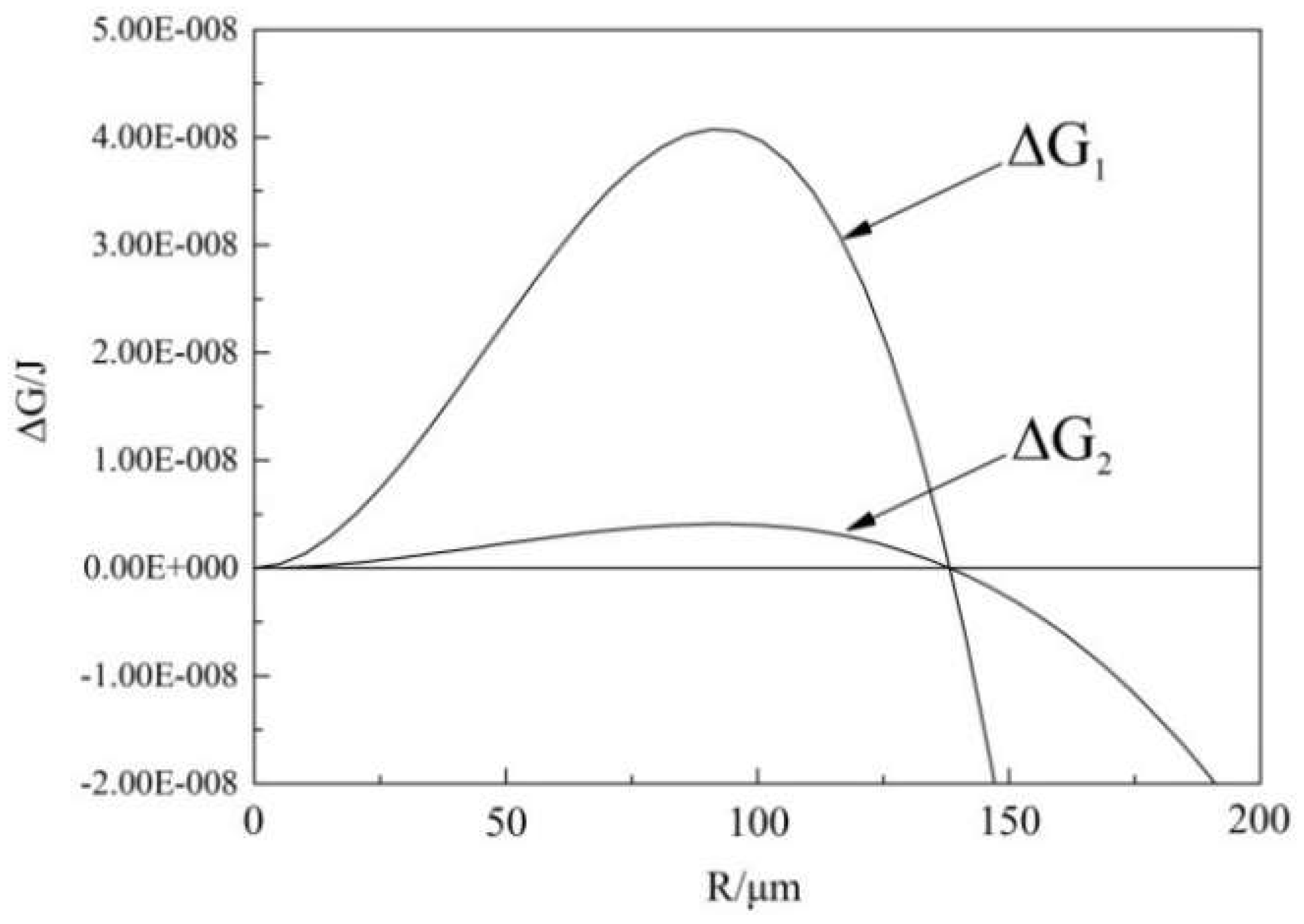
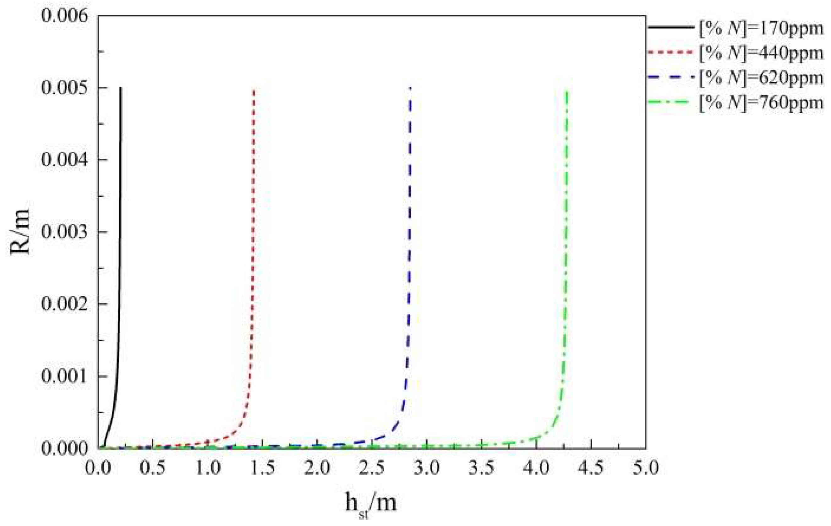
4.1. The Effect of Nitrogen Content on Depth Range of Bubble Nucleation

The dissolution of nitrogen in molten steel is in accordance with Sievert’s law. It can be derived that the relationship between the nitrogen content and the partial pressure of nitrogen is as follows:
P N 2 = ( [ % N ] f N K N ) 2 P θ
In which P N 2 and P θ are nitrogen addition pressure and standard atmospheric pressure, respectively. K N is the equilibrium constant of nitrogen dissolution reaction and the value is 0.044% [29]. f N is the activity coefficient of nitrogen. In dilute solution, the value of f N is approximately 1.
Thermodynamic calculation indicates that critical radii expression for the homogeneous and heterogeneous nucleation processes are the same, as shown in Equation (2) [28]:
R = 4 σ L G ( 1.5 + ln P v a c + ρ S g h s t P N 2 ) 3 ( P v a c + ρ S g h s t ) ln P v a c + ρ S g h s t P N 2
In which P v a c is the vacuum-treatment pressure; Pa, ρ S is the density of the molten steel; kg m 3 , g is the acceleration due to gravity; m s 2 , h s t is the melt depth where the gas bubbles are generated; and m, σ L G is the liquid/gas interface energy, J m 2 .
Substituting Equation (1) to Equation (2), the relationship between the critical nucleation radius of bubbles and the depth of the molten steel under different nitrogen content can be obtained when the vacuum pressure is 10−4 bar, as shown in Figure 10. The calculation parameters are shown in Table 3.
It can be seen from Figure 10 that the critical radius of the bubble increased slightly at first and then increased rapidly with the increase of the depth of the molten steel under the same nitrogen content. This indicates that the amount of solution required for bubble nucleation increases with the increase of the depth, which leads to the difficulty of bubble nucleation increased. This means that the depth range of bubble nucleation in molten steel increases with the increase of nitrogen contents. Therefore, the increase of the nitrogen content of molten steel can increase the depth range of bubble nucleation effectively.

4.2. Effect of Nitrogen Content on Bubble Nucleation Rate

The bubble nucleation rate refers to the number of bubble nuclei formed in per unit time and unit volume. Bubble nucleation rate can reflect the difficulty of bubble nucleation and the density of bubbles. The expression of bubble nucleation rate was shown in Equation (3) [31]:
N = m K T h e exp ( W K T ) exp ( Δ G A K T )
In which m is the number of gas atoms per unit volume, h e is Planck’s constant, K is Boltzmann’s constant, Δ G A is the diffusion activation energy of the atom, and T is the temperature of molten steel. W is the nucleation energy of heterogeneous nucleation and its expression is as follows [32]:
W = 4 3 π R 2 σ L G f ( θ )
In which f ( θ ) is the shape coefficient and 0 < f ( θ ) < 1 under heterogeneous nucleation, and θ is contact angle between the molten steel and the inclusions. The expression of Δ G A is as follows [33]:
Δ G A = K T f exp ( a T )
In which f and a are constants. Δ G A can be regarded as a constant at a specific temperature. The expression of the number of gas atoms per unit volume m is as follows:
m = 2 [ % N ] ρ S N A M N 2
In which M N 2 is nitrogen molar mass, g mol 1 . Substituting Equation (4), Equation (5), and Equation (6) into Equation (3), bubble nucleation rate N can be expressed as follows:
N = 2 [ % N ] ρ S N A K T M N 2 h e exp [ 4 π R 2 σ L G f ( θ ) 3 K T f exp ( a T ) ]
It can be inferred from Equation (7) that the part before the exponent increases with the increase of nitrogen contents. The critical radius decreases with the increase of nitrogen contents, which can increase the value of exponent term. Thus, the bubble nucleation rate increases with the increase of nitrogen contents. This indicates that with the increase of nitrogen content, the bubble nucleation becomes easier and the density of generated bubbles also increases, which can improve the effect of inclusion removal effectively.
In addition, the increase of nitrogen content provides more solute elements for bubble nucleation, and this will increase the number of bubbles in molten steel. It means that bubbles can nucleate on the surfaces of more inclusions and carry them to the slag. The elevation of bubbles number can also effectively increase the adhesion probability of inclusions effectively during the floating process [34]. In general, the increase of nitrogen content in molten steel can improve the inclusion removal significantly.

4.3. The Mechanism of the Pressure Elevating and Reducing Method (PERM) and NERM

Homogeneous nucleation refers to the process of forming a new phase core in liquid phase by its own structural and energy fluctuations. The change in the Gibbs free energy of the system Δ G 1 for the homogeneous nucleation can be expressed as follows [28]:
Δ G 1 = 4 π R 2 σ L G + 0.16 π R g ( P v a c R 3 + ρ S g h s t R 3 + 2 σ L G R 2 ) ln P v a c + ρ S g h s t P N 2
Heterogeneous nucleation refers to the phenomenon of forming a new phase core on the surface of particles in the liquid phase. The change in the Gibbs free energy for the heterogeneous nucleation Δ G 2 can be expressed as follows [28]:
Δ G 2 = Δ G 1 f ( θ )
The expression of f ( θ ) can be written as follows:
f ( θ ) = 2 + 3 cos θ cos 3 θ 4
Taking Al2O3 inclusion as an example (the contact angle is 144°), the difference of change in Gibbs free energy between bubble homogeneous nucleation and heterogeneous nucleation was calculated when the vacuum pressure of 10−4 bar and depth of molten steel was 1 m, respectively. The molten steel was pretreated with nitrogen at a pressure of 1 bar at 1873 K. The calculation result is shown in Figure 11.
Bubbles can nucleate when the expression d Δ G / d r = 0 is satisfied. The peak value of Δ G 2 is much lower than Δ G 1 in Figure 11. This indicates that the bubble needs to overcome more energy barriers when it formed by homogeneous nucleation. Thus, bubbles are more easily generated by heterogeneous nucleation. Inclusions in the molten steel can be the cores for the heterogeneous nucleation. There are a large number of inclusions in molten steel, and the distribution is diffused, so a large number of diffused bubbles can generate. The diffused bubbles have a high probability of adhesion to inclusions in the floatation process, and inclusions can be removed effectively through bubble adhesion. Additionally, this is the basic mechanism of NERM and PERM.
The amount of solute required for bubble nucleation increases with the increase of the critical radius, which will make the nucleation more difficult. Therefore, it is assumed that the bubble nucleus larger than 100 μm cannot form in the molten steel. The results of thermodynamic calculation show that the depth of bubble nucleation is 0–0.18 m by NERM under the conditions of the industrial trial. Even when the nitrogen content is 440 ppm (saturated nitrogen content of the molten steel under atmospheric pressure), the depth range of bubble nucleation is only 0–1.42 m. Thus, bubbles can only nucleate in the upper part of the molten steel by NERM. However, the argon gas was blown from the bottom of the ladle in vacuum process, so that the molten steel in the lower part of the ladle can move upwards. The inclusions contained in this part of molten steel also move to the upper part; bubbles can nucleate on the surface of them and float to the top (as shown in Figure 12). By this means, inclusions with a large depth of molten steel can be removed.
Thermodynamic calculations show that the depth range of bubble nucleation can reach 0–3.98 m when the nitrogen content is 760 ppm. In the VON/VAD experiment using the PERM, the initial nitrogen content of the stainless steel was about 1400 ppm, and the depth of molten steel was about 3.9 m. For the reason that the depth range of bubble nucleation increases with the increase of nitrogen content, the bubbles can nucleate within the full depth of molten steel using PERM (as shown in Figure 12). Thus, the mechanisms of these two methods are different.
Although the results of industrial trial show that the two refining methods can remove the inclusions in steel significantly, the PERM requires pressure treatment of the ladle system, which has a high requirement on the equipment. However, NERM has the advantages that the molten steel can be treated under normal or low pressure using the existing processes in steel plant without retrofitting equipment or increasing process time. Therefore, NERM is more applicable, and it is expected to achieve industrial applications in the future.

5. Conclusions

(1)
Using NERM can remove the inclusions in steel effectively in actual industrial production. Compared with conventional method, the amount of inclusions was reduced by 52.9% by NERM. In addition, the number of inclusions smaller than 3 μm in billet was reduced significantly, and the inclusions larger than 10 μm were completely removed.
(2)
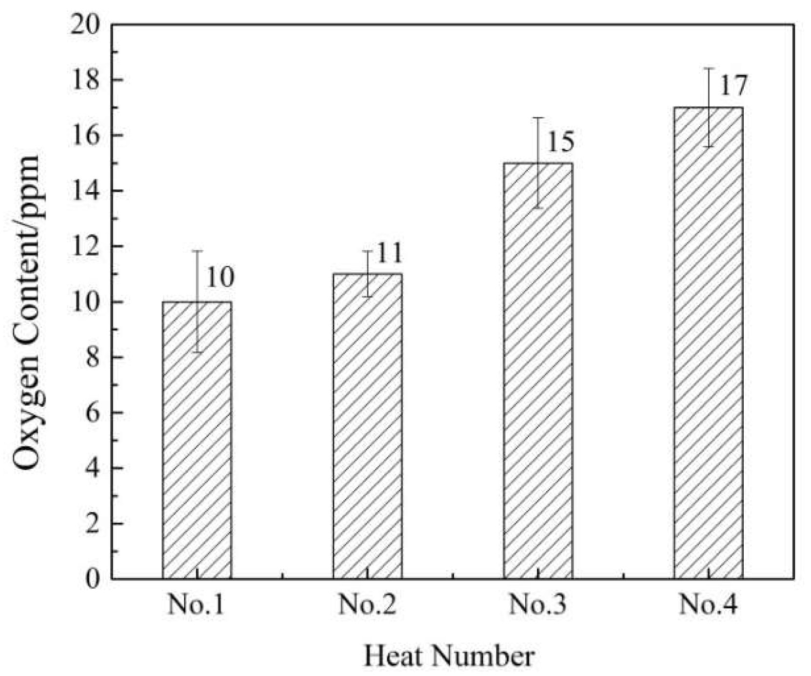
The average oxygen content in billets was 10.5 ppm after the treatment of NERM. The average oxygen content in billets was 16 ppm using conventional method. The average oxygen content of the billets decreased by 34.38%.
(3)
The increase of nitrogen content in molten steel reduces the difficulty of bubble nucleation. The number and the density of bubbles increase with the increase of nitrogen content, which can improve the removal effect of inclusions.
(4)
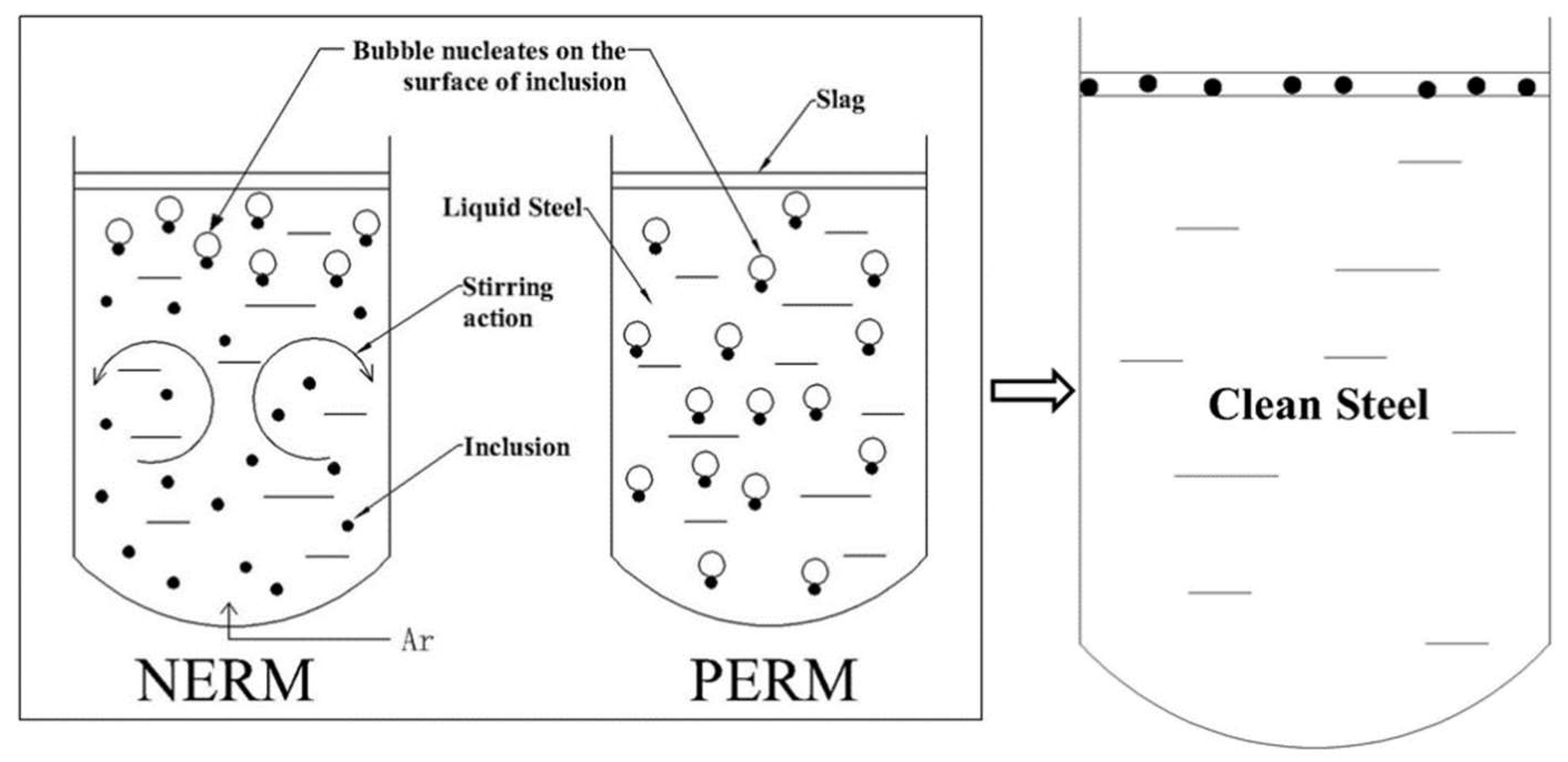
Bubbles can only nucleate in the upper part of the molten steel by NERM. However, the argon gas was blown from the bottom of the molten steel in the vacuum process, so that the molten steel in the lower part of the ladle move upwards. The inclusions contained in this part of molten steel also move to the upper part of the molten steel; bubbles can nucleate on the surface of them and float to the top, while bubbles can nucleate within the full depth of molten steel using PERM.
(5)
NERM has the advantage that molten steel can be treated under normal or low pressures with the existing processes in a steel plant without retrofitting equipment or increasing the process time. NERM is more applicable.

Author Contributions

Investigation, J.Z., S.Y., D.D., G.W., and S.L.; Project administration, J.L.; Writing—original draft, J.Z. and J.L.; Writing—review & editing, J.Z. and J.L.

Funding

This work was financially supported by the National Natural Science Foundation of China (Grant No. 51574022).

Acknowledgments

Thanks are given to the HBIS Group SHISTEEL Company. This work was supported by the National Natural Science Foundation of China (Grant No. 51574022).

Conflicts of Interest

The authors declare no competing interests.

References

  1. Han, L.H.; Huo, J.S. Concrete-filled hollow structural steel columns after exposure to ISO834 fire standard. J. Struct. Eng.-Asce. 2003, 129, 68–78. [Google Scholar] [CrossRef]
  2. Naser, M.Z.; Kodur, V.K.R. Comparative fire behavior of composite girders under flexural and shear loading. Thin Wall. Struct. 2017, 116, 82–90. [Google Scholar] [CrossRef]
  3. Naser, M.Z.; Chehab, A.I. Materials and design concepts for space-resilient structures. Prog. Aerosp. Sci. 2018, 98, 74–90. [Google Scholar] [CrossRef]
  4. Jyri, O.; Pentti, M. Mechanical properties of structural steel at elevated temperatures and after cooling down. Fire Mater. 2010, 28, 237–251. [Google Scholar]
  5. International Iron and Steel Institute. State of the Art and Process Technology in Clean Steelmaking; International Iron and Steel Institute: Beijing, China, 2006. [Google Scholar]
  6. Xu, Z. Secondary Refining; Metallurgical Industry Press: Beijing, China, 1994. [Google Scholar]
  7. Gao, H.C.; Yan, G.F. Problems about process theory in production pf clean steel by electromagnetic stirring in ladle. Res. Iron Steel 2003, 3, 14–18. [Google Scholar]
  8. Miki, Y.; Kitaoka, H.; Bessho, N. Inclusion separation from molten steel in tundish with rotating electromagnetic field. Tetsu Hagane 2009, 82, 498–503. [Google Scholar] [CrossRef]
  9. Nakanishi, K. Japanese State of the art continuous casting process. Trans. Iron Steel Inst. Jpn. 2007, 36, S14–S17. [Google Scholar] [CrossRef]
  10. Zhan, D.P.; Song, J.X.; Jiang, Z.H. Application effect of electromagnetic brake in continuous casting mold. China Metall. 2006, 16, 23–25. [Google Scholar]
  11. Mazumdar, D.; Guthrie, R.I.L. The physical and mathematical modelling of gas stirred ladle systems. ISIJ Int. 1995, 35, 1–20. [Google Scholar] [CrossRef]
  12. Wang, L.; LEE, H.G.; Hayes, P. A new approach to molten steel refining using fine gas bubbles. ISIJ Int. 1996, 36, 17–24. [Google Scholar] [CrossRef]
  13. Zheng, X.; Hayes, P.C.; Lee, H.G. Particle removal from liquid phase using fine gas bubbles. ISIJ Int. 1997, 37, 1091–1097. [Google Scholar] [CrossRef]
  14. Zhan, S.H.; Wang, J.J.; Qiu, S.T.; Xiao, Z.Q.; Gan, Y. Flow control and inclusion removal in continuous casting tundish with bottom gas blowing. J. Anhui Univ. Technol. 2006, 23, 367–372. [Google Scholar]
  15. Turkdogan, E.T. Novel concept of cleansing liquid steel of solid oxide inclusions by cullet injection in ladle. Ironmak. Steelmak. 2004, 31, 131–134. [Google Scholar] [CrossRef]
  16. Matsuno, H.; Kikuchi, Y.; Komatsu, M. Development of a new deoxidation technique for rh degassers. Iron Steelmak. 1993, 20, 35–38. [Google Scholar]
  17. Bai, X.Q.; Li, D.H.; Zhang, L. Ultrasonic separation of inclusions from flow liquid. Acta. Metall. Etall. Sin. 2002, 38, 483–489. [Google Scholar]
  18. Li, K.W.; Liu, J.H.; Zhou, J.B. Micro non-metallic inclusion removal from molten steel with gas bubbles generated by the nitrogen absorbing and releasing method. Chin. J. Eng. 2015, 37, 1124–1129. [Google Scholar]
  19. Wang, L.; LEE, H.G.; Hayes, P. Prediction of the optimum bubble size for inclusion removal from molten steel by flotation. ISIJ Int. 1996, 36, 7–16. [Google Scholar] [CrossRef]
  20. Bessho, N.; Yamasaki, H.; Fujii, T. Removal of inclusion from molten steel in continuous casting tundish. ISIJ Int. 1992, 32, 157–163. [Google Scholar] [CrossRef]
  21. Wang, L.T.; Zhanq, Q.Y.; Peng, S.H. Fundamental of inclusion removal from molten steel by rising bubble. J. Iron Steel Res Int. 2004, 11, 5–9. [Google Scholar]
  22. Zhu, M.Y.; Xiao, Z.Q. Physical and Mathematical Simulation of Steel Refining Process; Metallurgical Industry Press: Beijing, China, 1998. [Google Scholar]
  23. Zhang, L.F.; Taniguchi, S. Fundamentals of inclusion removal from liquid steel by bubble flotation. Int. Mater. Rev. 2000, 45, 59–82. [Google Scholar] [CrossRef]
  24. Liu, H.; Liu, J.; Michelic, S.K. Characterization and analysis of non-metallic inclusions in low-carbon Fe–Mn–Si–Al TWIP steels. Steel Res. Int. 2016, 87, 1723–1732. [Google Scholar] [CrossRef]
  25. Han, Z.J.; Lin, P.; Liu, L.; Cui, J.Y.; Zhou, D.G. Thermodynamics of calcium treatment for 20CrMnTiH1. Iron Steel 2007, 9, 32–36. [Google Scholar]
  26. Diederichs, R.; Bleck, W. Modelling of manganese sulphide formation during solidification, part I: Description of mns formation parameters. Steel Res. Int. 2006, 77, 202–209. [Google Scholar] [CrossRef]
  27. Turkdogan E, T. Fundamentals of Steelmaking; The Institute of Materials: London, UK, 1996. [Google Scholar]
  28. Li, K.W.; Liu, J.H.; Zhang, J. Theoretical analysis of bubble nucleation in molten steel supersaturated with nitrogen or hydrogen. Metall. Mater. Trans. B 2017, 48, 2136–2146. [Google Scholar] [CrossRef]
  29. Huang, X.H. Principal of Iron and Steel Metallurgy, 3rd ed.; Metallurgical Industry Press: Beijing, China, 2002. [Google Scholar]
  30. Szekely, J.; Martins, G.P. Non-equilibrium effects in the growth of spherical gas bubbles due to solute diffusion. Chen. Eng. Sci. 1971, 26, 147–159. [Google Scholar] [CrossRef]
  31. Turnbull, D. Formation of crystal nuclei in liquid metals. J. Appl. Phys. 1950, 21, 1022–1028. [Google Scholar] [CrossRef]
  32. Cui, Z.Y. Metallography and Heat Treatment; Harbin Institute of Technology Press: Harbin, China, 1998. [Google Scholar]
  33. Tiller, W.A.; Jackson, K.A.; Rutter, J.W. The redistribution of solute atoms during the solidification of metals. Acta Metal. 1953, 1, 428–437. [Google Scholar] [CrossRef]
  34. Xue, Z.L.; Wang, Y.F.; Wang, L.T. Inclusion removal from molten steel by attachment small bubbles. Acta Metall. Sin. 2003, 39, 431–434. [Google Scholar]
Figure 1. The process comparison of the two refining methods: (a) conventional method and (b) Nitrogen Elevating and Reducing Method (NERM).
Metals 08 00560 g001
Figure 2. The number of samples.
Metals 08 00560 g002
Figure 3. Schematic diagram of sampling.
Metals 08 00560 g003
Figure 4. Changes of nitrogen content in steel at each process. (a) nitrogen contents of No. 1 heat; (b) nitrogen contents of No. 2 heat; (c) nitrogen contents of No. 3 heat; (d) nitrogen contents of No. 4 heat.
Metals 08 00560 g004
Figure 5. The oxygen content of the billets.
Metals 08 00560 g005
Figure 6. The number of different types of inclusions in billets.
Metals 08 00560 g006
Figure 7. Surface scan of CaS-MnS-Al2O3 inclusions. (a) spherical CaS-MnS-Al2O3 inclusion; (b) approximate spherical CaS-MnS-Al2O3 inclusion.
Metals 08 00560 g007aMetals 08 00560 g007b
Figure 8. The morphology of Al2O3 inclusions. (a) irregular Al2O3 inclusion; (b) triangular Al2O3 inclusion.
Metals 08 00560 g008
Figure 9. The number densities of inclusions in each billet.
Metals 08 00560 g009
Figure 10. Relationship between the critical nucleation radius of bubbles and the melt depth under different nitrogen content.
Metals 08 00560 g010
Figure 11. The changes in Gibbs free energy of bubble homogeneous nucleation and heterogeneous nucleation under same conditions.
Metals 08 00560 g011
Figure 12. Comparison of mechanism of inclusion removal by NERM and PERM.
Metals 08 00560 g012
Table 1. The main chemical composition of the experimental steel in the trial, wt %.
ElementCSiMnPSCrAls
%0.2080.2250.5570.0160.0050.9070.02
Table 2. The main chemical composition of slag in the trial, wt %.
ElementCaOAl2O3SiO2MgOOther
%50.9130.819.754.923.61
Table 3. Parameters and values used in calculation.
Parameters R g / J mol 1 K 1 ρ S / kg m 3 σ LG / J m 2 M N 2 / g mol 1
Values8.31470001.5 [30]28

