Rocking and Kinematic Approaches for Rigid Block Analysis of Masonry Walls: State of the Art and Recent Developments


1
Department of Structures for Engineering and Architecture, University of Naples Federico II, Via Forno vecchio, 36, 80124 Naples, Italy
2
Department of Energy Systems, Territory and Constructions Engineering, University of Pisa, Largo Lucio Lazzarino, 1, 56100 Pisa, Italy
3
ISISE, Department of Civil Engineering, University of Minho, Campus de Azurem, 4800 - 058 Guimarães, Portugal
*
Author to whom correspondence should be addressed.
Buildings 2017, 7(3), 69; https://doi.org/10.3390/buildings7030069
Submission received: 12 April 2017
/
Revised: 24 July 2017
/
Accepted: 1 August 2017
/
Published: 4 August 2017
(This article belongs to the Special Issue Traditional and Innovative Approaches in Seismic Design)
Abstract
:The assessment of the rocking and overturning response of rigid blocks to earthquakes is a complex task, due to its high sensitivity to the input motion, variations in geometry and dissipation issues. This paper presents a literature review dealing with classical and advanced approaches on rocking motion with particular reference to masonry walls characterized by a monolithic behavior. Firstly, the pioneering work of Housner based on the concept of the inverted pendulum is discussed in terms of the most significant parameters, i.e., the size and slenderness of the blocks, the coefficient of restitution and ground motion properties. Free and restrained rocking blocks are considered. Then, static force-based approaches and performance-based techniques, mostly based on limit analysis theory, are presented to highlight the importance of investigating the evolution of the rocking mechanisms by means of pushover curves characterized by negative stiffness. From a dynamic perspective, a review of probabilistic approaches is also presented, evaluating the cumulative probability of exceedance of any response level by considering different earthquake time histories. Some recent simplified approaches based on the critical rocking response and the worst-case scenario are illustrated, as well.
1. Introduction
Masonry buildings are constituted of three-dimensional assemblies of walls, where the out-of-plane behavior of each wall is highly influenced by the type and strength of connection with the others. There are traditional (e.g., steel ties or buttresses [1]) and innovative (e.g., composites [2,3]) techniques to ensure a safe seismic behavior at the local level, by considering the typical biaxial stress state that could involve energy dissipation [4,5,6]. Nevertheless, when a global box-type behavior is not guaranteed, the walls, especially the peripheral ones, are more vulnerable to out-of-plane overturning, which is one of the main causes of damage or collapse induced by earthquakes on existing masonry structures. The main deficiencies are the lack of proper connections between orthogonal walls, the absence of connecting ties, insufficiently rigid floor diaphragms, low strength and deterioration of materials.
However, if a monolithic behavior can be assured for such walls, they can be regarded as rigid blocks, and their out-of-plane seismic response can be treated through two fundamental approaches on which this paper is mainly focused: rocking dynamics and kinematic analysis. Discrete and finite elements can also be used to assess the response of masonry structures under earthquakes [7], but those involve many uncertainties mainly related to the definition of the constitutive laws of the materials and are more suitable to masonry walls far from monolithic behavior.
On the other hand, the apparent simplicity of the rocking of a single-degree-of-freedom (SDOF) rigid block hides many subtle phenomena, largely investigated in the literature, with more emphasis since the 1980s. The pioneering work of Housner [8] was the basis for the subsequent research in the field of rocking blocks, studied in structural dynamics and particularly in earthquake engineering. After him, the first modern contributions to the rocking issues are due to Aslam and Scalise [9], who considered the motion of a free rocking block subjected to ground motions. They analyzed the transition to the sliding phenomenon, as well. The work of Ishiyama [10] proposed analytical formulations for the transitions between different types of motion (sliding, rotation, translational or rotational jumping).
Despite the numerous studies carried out so far on rigid body rocking (an extensive review work on this subject is reported in [11]), little literature describing the state of the art on masonry walls treated as rigid bodies is available, let alone the rocking of restrained walls. Therefore, this paper proposes an extensive review on kinematic and rocking approaches for monolithic masonry walls, specifically regarded as rigid blocks on rigid foundations, also including recent developments and different models accounting for lateral constraints. These modeling approaches can be used for defining the non-linear static and dynamic response of masonry buildings, especially the historic ones, for which macro-elements and their connections play a crucial role in the seismic vulnerability assessment [12,13,14,15,16].
The kinematic approach includes static force-based and displacement-based approaches based on standard and non-standard limit analysis methods, taking into account the evolution of motion over time through incremental kinematic analysis, while dynamic effects are considered more appropriately by means of the dynamic approach, since it also accounts for the energy dissipation in the motion.
The aim of this work is to illustrate and discuss the issues involved in the classical and non-classical theories and to present the two above-mentioned approaches adapted to masonry structures. In addition, emerging design techniques are illustrated to clarify the direction in which the research is practically oriented. Section 2 describes the basics of the rocking of a free-standing single-degree-of-freedom block, whereas Section 3 introduces the issue of restrained blocks, with an extension to multi-degree-of-freedom (MDOF) systems in Section 4. Section 5 illustrates the static approaches, referring to the static force-based and displacement-based approaches. The last two sections comment on the influence of the input motion parameters on the dynamic response (Section 6) and the deterministic and probabilistic methods of the rocking analysis (Section 7).
2. Rocking of Free-Standing SDOF Block
2.1. The Classical Theoretical Model of Housner and the Main Geometric Parameters Influencing Rocking
Housner’s formulation [8], referred to as classical theory in this paper, allows investigating the behavior of a rigid block on a rigid foundation under transient actions such as earthquakes. The considered single-degree-of-freedom (SDOF) block is a rigid prism with a rectangular cross-section, rocking about the two corners O and O’ (Figure 1a) and supported by a flat rigid base. Neither bouncing nor sliding are considered in this formulation.
The main geometric parameters influencing the rocking response are two: (i) slenderness ratio α, namely the arctangent of thickness to height ; and (ii) radius vector R, which connects the pivot point to the block center of mass.
Considering the rotation ϑ (>0 if counter-clockwise) as a Lagrangian coordinate, the equation of motion takes the form:
where is the inertia moment, the mass and the acceleration time-history (in g) of the mass. Equation (1) can be modified for homogeneous prismatic blocks as follows:
where p is the frequency parameter, equal to .
The equation of motion governing the rocking phenomenon of a free-standing rigid block is analogous to that used for investigating the response of a free-standing block with additional mass. A mass placed at the top of the block could simulate a roof mass, whose effect is one of changing the centroid of the composed system block + mass (Figure 1b). Thus, the inertia moment accordingly changes, with multiple values of radius and slenderness, but the equation of motion is basically the same as that of Housner’s model (see Section 3) [17].
A relevant finding of the classical theory is that, between two rigid rectangular blocks of the same slenderness, the block with the higher radius vector is more stable. Moreover, between two blocks of the same width, the taller block is more stable than the shorter one [18]. However, the shorter block is related to a smaller amplitude of ground acceleration than that of the taller one. In addition, Kounadis [18] specifies that this behavior is not valid in the case of shocks, when the resisting forces (including inertia) do not have enough time to react, and the taller block results in being less stable than the shorter one (when overturning occurs without impact).
2.2. Geometry Influence and the Formulation of Energy Dissipation
The classical theory considers a rectangular block, but normally, asymmetric blocks or blocks with different shapes are to be modeled. Many authors studied the changes in the equations of motion caused by the modified geometry. These changes affect the following elements:
- moments of inertia and radius vector;
- energy loss at each impact and/or restitution coefficient;
- 3D motion to be considered instead of 2D motion;
- bouncing effect in the case of stocky blocks;
- additional terms in the equation of motion such as those due to damping and springs.
The energy dissipation or damping over rocking motion occurs when the block hits the base and the pivot point suddenly changes from O to O’ (Figure 1). In the classical theory, the energy loss is expressed as a reduction of kinetic energy after each impact. By equating the moment of momentum about O’ immediately before impact to that immediately after impact, Housner found the following expression, valid for slender and rectangular blocks:
where is the height to thickness ratio. The so-called “restitution coefficient” depends on the slenderness ratio : the higher the slenderness, the higher the number of impacts to get the same energy loss for the same input action. A value of means totally inelastic impact, whilst indicates a perfectly elastic impact. Generally, the energy loss during impact is lower in experiments than that predicted by Housner’s model. In other words, the experimental value of the restitution coefficient is higher than the theoretical one .
Experimental tests were performed to identify the values of restitution coefficients for different unreinforced masonry (URM) specimens of several construction materials and slenderness ratios. Liberatore et al. [19] tested a marble block rocking on a marble foundation, whereas Aslam et al. [9] tested a concrete block with an aluminum base rocking on a steel foundation. They noticed discrepancies of the restitution coefficients’ values between experimental and analytical results. A relevant contribution was also given by Lipscombe and Pellegrino [20], who conducted four free rocking tests on steel blocks with colliding on a steel base. The blocks, initially tilted almost to the point of overturning and then released, exhibited values of restitution coefficients ranging between 0.88 and 0.93, although it was respectively (given by Equation (3)) for the mentioned values. Peña et al. [21] performed experimental tests on granite stones with the height to thickness ratio varying from 4–8 under free-vibrations, harmonic and random motions. The restitution coefficient was found to be slightly higher than the experimental one, as the real case does not fully comply with the hypotheses of no bouncing or an ideal block. Indeed, the body not being fully rigid, the moment of momentum was not conserved. In this line, also Sorrentino et al. [22] carried out an experimental campaign on URM solid clay brick or tuff specimens for two-sided and one-sided motion, with height to thickness ratios varying between 6.5 and 14.6. The authors found values of the restitution coefficient equal to 95% of the theoretical value. On the other hand, the lower energy loss during impact in most experiments is related to the unevenness of the colliding surfaces, generating consecutive impacts that reduce the energy loss. That aspect was recently analytically modeled with additional pseudo-bumps at any position of the section. These bumps change the evolution of motion as more impacts occur; the modified equations of motion are proposed in [23]. Recent experimental tests observed relevant results on the evaluation of the coefficient of restitution and motion decay [24,25,26,27]. It was shown how the interface material strongly influences the dissipation in the free rocking behavior. Blocks tested on rubber were seen to have the fastest energy dissipation followed by concrete and timber bases [24]. An improved estimation of the coefficient of restitution was proposed in [26] to accurately quantify the energy dissipation of free rocking members. In addition, even for symmetric structures with uniaxial shaking, multiple modes and three-dimensional responses are likely to occur [25].
2.3. Bouncing: Sliding Phenomena and the Role of Vertical Ground Motion
In the classical theory, bouncing and sliding are neglected, but these phenomena have to be sometimes necessarily considered. Indeed, for stocky blocks, say , bouncing was shown to occur, and the response was seen to be very sensitive to the restitution coefficient value [20]. For these blocks, such as cubes, a two-dimensional or three-dimensional bouncing model is therefore required. In this case, the determination of a restitution coefficient is then crucial to get a reliable response. The impact response of short blocks is therefore complex to predict for these stocky structures. In [20], a probabilistic approach was suggested to solve this issue. As concerns sliding, the absence of it is acceptable when the static coefficient of friction is larger than the ratio b/h [22,28]. Generally, masonry walls have this ratio much lower than the static friction coefficient, usually equal to 0.6–0.7 [28].
As regards the vertical ground acceleration, this was shown to have a marginal effect on the stability of a free-standing rocking column [29]. As the authors highlight, this is due to the fact that the ground acceleration enters the equation of motion after being multiplied with sin () ≪ 1, whereas the horizontal acceleration enters the equation of motion after being multiplied by cos () ≈ 1.
3. Restrained Rocking Blocks
In real conditions, rocking blocks such as masonry walls are restrained by flexible diaphragms. Several authors studied the influence of these boundary conditions on the dynamic response through analytical models [30], showing that diaphragm and shear-wall accelerations might increase with the flexibility of the diaphragm.
Housner’s equation of motion was modified for considering the effect of single or smeared horizontal restraint [31] following a variational formulation. A single spring (or bed spring) was considered to have axial stiffness (or per unit of length) simulating an element with a stabilizing effect, such as a strengthening device (tie-rod), transverse walls or flexible diaphragms. The stiffness or can assume different values depending on the type of the roof and on the type of the roof-wall connection.
Due to the eccentricity of the roof mass, the radius vector changes depending on the rotation sign, for clockwise and for counterclockwise rotations, respectively (Figure 2, [17]). However, for slender blocks, the difference between and is negligible, and the radius vector can be assumed as the double of the radius vector .
If is the current roof radius vector and the block, subjected to a horizontal thrust , is connected to a single horizontal restraint with stiffness , the equation of motion reads [17]:
where the polar moment includes the contribution of the roof mass, and , is the block mass and is the acceleration time-history (in gravity acceleration g units) of the mass.
The direction and magnitude of the vector may be assumed constant during motion in the hypothesis of small displacements or acting up to a fixed displacement given, for instance, by the Mohr–Coulomb law. A higher centroid position is due to the presence of the roof mass. Indeed, the roof mass is assumed to participate in the rocking motion by rotating together with the masonry block. In the case of no eccentricity (, Figure 1b), the distance of the centroid of the composed system Gc from the base is:
and the inertia moment of the system is obtained with the following expression:
where is the polar inertia moment with respect to the base corner O, .
The effect of vertical restrainers with elastic pre-stressed tendons was also investigated [25]. These systems were shown to be effective in improving the response of rocking frames with small columns subjected to long-period excitations. As the size of the columns, the frequency of the excitations or the weight of the cap-beam increases, the vertical tendons do not apply any beneficial effect. Indeed, the resistance of tall rocking frames primarily originates from the mobilization of the rotational inertia of the columns.
4. Extension of SDOF to MDOF Rocking Blocks
Significant equivalence methods allowed extending the results obtained for an SDOF free-standing block to more complex structures, such as rocking frames and masonry arches. Sometimes, flexural bending movements can occur in the out-of-plane failure modes of masonry walls, and the degree of freedom cannot always be assimilated to one. In such cases, the multi rigid body dynamics could be more suitable to represent the structural response [32,33]. In [33], several tests on scale models of masonry 3D assemblies were performed on a shaking table, subjected to sinusoidal input of varying frequency and displacement amplitude, but constant acceleration, and a simplified multi-degree-of-freedom (MDOF) model was presented based on the relative rocking of two portions of walls, each one made of a finite number of bricks. A two-degree-of-freedom (2DOF) model was also presented by Simsir et al. [32] to compute the out-of-plane response of a wall that cracks at the bed joints. This model accounts for the flexibility of the diaphragm, the stiffness of the wall and the possibility for horizontal cracks developing under combined flexural moments and axial forces.
However, in contrast to the single rocking block applied to masonry that has been examined extensively, the dynamic behavior of masonry structures regarded as multi-block structures has not, to date, been exhaustively studied because of its complexity. Therefore, in order to prompt the scientific research in this line, it is here briefly illustrated how the rocking analysis can be applied to MDOF blocks.
When the degree of freedom is one, even with more complex structures, the response is determined by carrying out the same analysis as the free-standing block, but by assuming a modified value of the frequency parameter p. The square of the frequency parameter is the ratio of restoring the moment to the polar moment of inertia . For an SDOF rectangular block, the frequency parameter is equal to . The dynamic equivalence between a free-standing rocking frame and a free-standing rocking column was first shown by Makris and Vassiliou [34]. It refers to a rocking frame, made by a set of columns of mass and a cap beam of mass . The frequency ratio of a rocking frame is given by where [34].
The results were extended to the case of an asymmetric rocking frame and the hinging masonry arch, defining proper values of for each structural system [35]. When the Lagrangian parameter is not only one rotation, namely the system is MDOF, the analysis becomes much more challenging. The pure rocking of two or three-degree-of-freedom systems was investigated in [36]. The number Nu of configuration patterns that may lead to overturning instability for an MDOF with n blocks is:
with corresponding total number of nonlinear differential equations .
Two-DOF systems were first studied in [37]. A relevant contribution to the definition of the dynamics of such systems was given by [38]: in this work, the equations of motion are obtained for each of the four + four modes (Figure 3), and criteria for the initiation of rocking and the transition between them are illustrated. In particular, the discussion of the impact between the lower block and the ground surface, together with the impact with the higher block and the lower one is performed. More recently, other works faced the more complex problem of 3DOF systems, generally solved only with analytical approaches, e.g., in [39], equations of motion are proposed to describe the response of multi-drum ancient Greek columns as 3DOF systems, to which 26 configuration patterns are associated.
5. Static Approaches
5.1. Static Force-Based Approaches: Standard and Non-Standard Limit Analysis Methods
The static force-based (FB) approach is the most common and the simplest tool to estimate seismic design forces on rocking rigid blocks. It basically consists of the application of the plasticity theory, as first formulated by Kooharian [40] and Heyman [41]. According to this method, recognized as standard limit analysis, the application of the static theorem provides a lower-bound or safe solution of the collapse load factor, based on equilibrium equations, while the application of the kinematic theorem leads to an upper bound multiplier. The solution that satisfies the hypotheses of both theorems, equilibrium, compatibility and material conditions is the correct solution and provides the collapse load multiplier for the specific problem.
The simple mechanical model is based on the following assumptions: blocks with infinite compressive strength (rigid blocks), joints with zero tensile strength and sliding failures not allowed (friction at interfaces is sufficiently high to prevent sliding/twisting).
Based on such assumptions, the maximum horizontal force that a rigid block can undergo at the onset of rotation can be obtained by imposing equilibrium conditions. For instance, the overturning equilibrium of a cantilever SDOF wall about the pivot point O (Figure 1a) can be used to determine :
where is the block mass. If is seen as the fraction of the block self-weight , it is possible to calculate the collapse multiplier or the maximum horizontal acceleration (in g) to which the block can be subjected in equilibrium conditions:
Similar equilibrium conditions can be imposed for blocks with different support conditions. For example, a load-bearing SDOF simply-supported wall (vertical-spanning wall) with a horizontal hinge at mid-height has a higher than that of a cantilever non-loadbearing wall. In particular, the force of the load-bearing simply-supported wall is times the force of the free-standing wall, where Ψ is the ratio of overburden weight and self-weight of the upper-half of the wall above mid-height [42].
In real conditions, rocking blocks such as masonry walls are restrained by horizontal diaphragms and transverse walls, as already mentioned above. In particular, in masonry buildings without a box-type behavior and subjected to seismic loadings, in-plane and out-of-plane failure mechanisms can take place where frictional resistances might play a predominant role. Hence, it is often necessary to consider the more realistic assumptions of the presence of sliding during rocking mechanisms and also to calibrate the role of friction with reference to other systems of resistance in masonry buildings (e.g., insertion of tie-rods, rigid diaphragms, etc.), as addressed in [13].
On the other hand, it is well known that when treating such so-called non-standard materials, the bounding theorems of plastic limit analysis do not generally provide unique solutions for collapse loads, due to the non-associated flow rules imposed by friction.
Drucker [43] was perhaps the first to point out that whilst the exact solution to a problem involving Coulomb friction interfaces could be bounded from above and below, unfortunately, such bounds will often be too wide to be of practical use. In this class of problems, in fact, the lower bound is generally the condition that assumes no friction and cannot obviously be proposed for the analysis of most masonry structures. A novel modeling strategy, based on a simplified macro-block approach, is capable of providing a closer range of solutions for the ultimate load factor [44] and a reliable solution falling within the range [45]. However, for the simple out-of-plane mechanism of a front wall interlocked with sidewalls involving vertical cogged cracks along the corners (laterally-constrained rigid block), the reliable solution can be computed directly by considering the full action of friction on the bed joints along the cracks. In fact, the frictional resistances can be expressed as [13]:
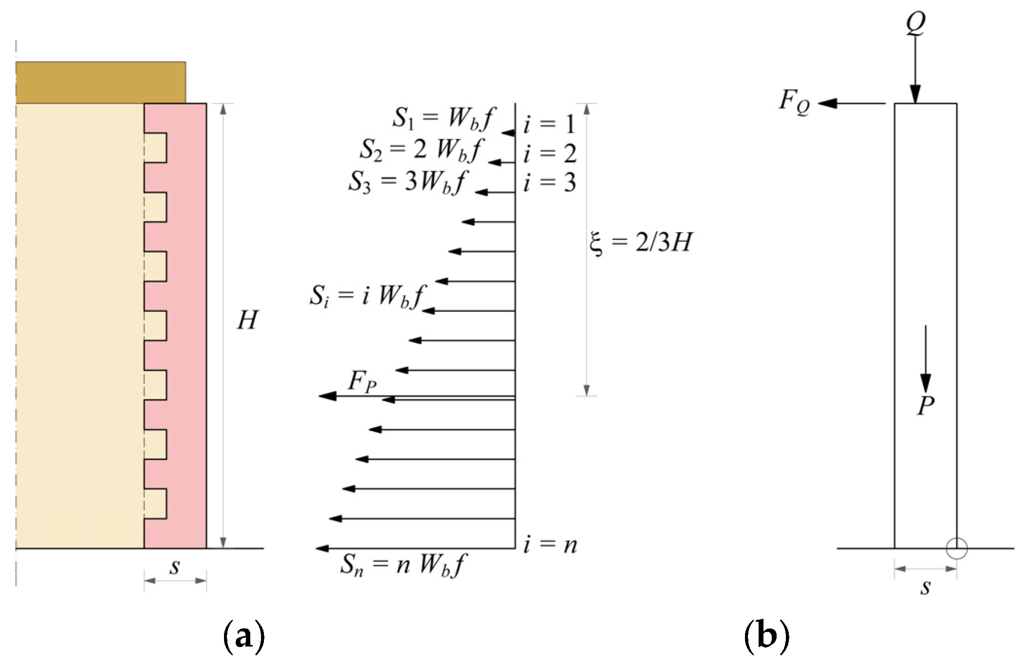
where n is the number of rows crossed by the vertical crack line (H = n × hb), t is the thickness of the sidewalls, f is the friction coefficient, hb and lb are the height and length of the single masonry unit, respectively, and Si is the single limiting shear force due to friction at contact interface i, obeying the cohesionless Coulomb’s law and stepwise increasing from the top to the bottom of the wall (Figure 4).
On the other hand, the presence of a horizontal diaphragm that is simply supported on the façade wall implies that beams can slip out, acting on the wall with a horizontal friction force, which is (cohesionless Coulomb’s law):
where fd is the beam-wall friction coefficient and Q is the vertical load transmitted to the wall. Thus, by imposing equilibrium, the activation load multiplier α0 for incipient rotation around the hinge at the base of the façade wall in Figure 4 is given by the expression:
where s is the thickness of the front wall and the vertical resultant of the overload is assumed, e.g., applied at s/3 from the internal edge.
In general, the static force-based approach is very useful for the identification of the failure mechanisms, especially when not self-evident, since it is based on minimization routines. However, the evaluation of the static multiplier is only related to the onset of rocking, not to the overturning that may occur under dynamic actions. In fact, the evolution of the dynamic system over time is neglected, and the reserve capacity of the rocking phenomenon is not considered.
5.2. Displacement-Based Approaches
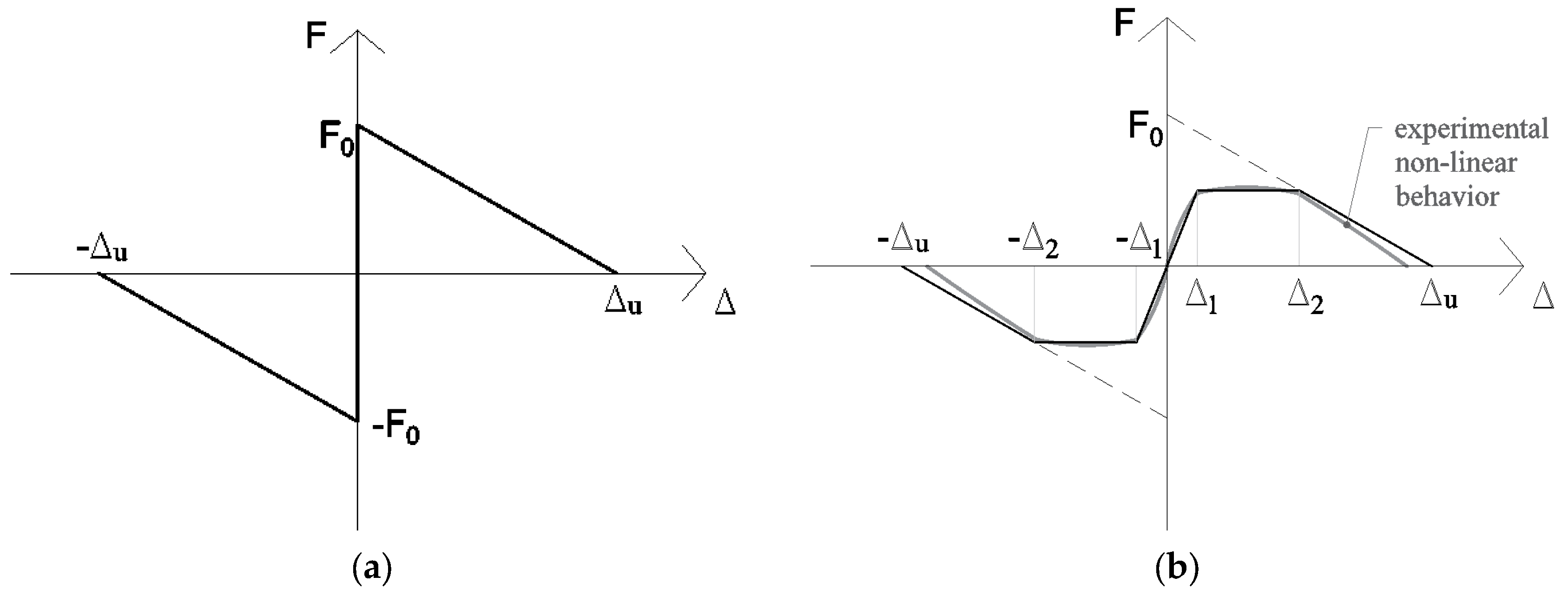
As dynamically-loaded walls can sustain accelerations well in excess of their ‘quasi-static’ capabilities [46], the displacement-based (DB) approach is revealed to be a more realistic tool to assess the seismic design forces on a rocking wall. A DB approach is based on a force-displacement law, which is different according to whether the model is ideal or has imperfections. The force-displacement function (analogous to a pushover curve) can be obtained by determining the total horizontal reaction (or base shear) at different displacements by using simple static equilibrium principles or the principle of virtual work. In the latter most adopted case, a non-linear kinematic analysis is applied by considering kinematic varied configurations of the mechanism, in large displacements. The ideal block has a moment-rotation or force-displacement law with negative stiffness (Figure 5a) once the force at the onset of rotation has been attained.
By contrast, geometrical imperfections cause the force-displacement law to be non-linear. In this case, the block is said to be “semi-rigid”. Generally, a tri-linear simplified force-displacement law with a finite initial stiffness is adopted (Figure 5b) [42]. The real block has therefore an initial branch with a finite stiffness, a plateau phase (between and ) and a third branch with negative stiffness up to an ultimate displacement (Figure 5). The ratios and are related to the material properties and the state of degradation of the mortar joints at the points of rotation. Some experimental tests were performed on URM specimens to obtain some values of those ratios [42]. A relevant parameter of the force-displacement law is the secant stiffness, which is amplitude dependent.
One method commonly used is to obtain the secant stiffness from the non-linear force-displacement curve corresponding to the point of maximum (permissible) displacement. For ductile systems, the point of maximum displacement is often associated with a point on the post-peak softening section of the non-linear force-displacement curve where the force has reduced to a fraction (generally 70–80%) of the peak force value.
For non-ductile structures such as masonry, the definition of secant stiffness is difficult due to material strength variability and a lack of yield and or unique softening points. The stiffness corresponding to a line going from the origin to the point of the curve with ∆ = ∆2 may be considered reasonably consistent [28]. A displacement-based procedure for rocking masonry structures was recently proposed [16]. It is compatible with the PERPETUATE (PERformance-based aPproach to Earthquake proTection of cUlturAlheriTage in European and mediterranean countries) methodology for the seismic performance-based assessment of cultural heritage [47] and is based on the following steps: (1) definition of the rocking mechanism (by considering rigid blocks, constraints, internal and external elasto-plastic links, constructive features and masonry quality); (2) evaluation of the pushover curve, by the incremental equilibrium limit analysis performed on varied kinematic configurations; (3) definition of performance levels (PLs), in terms of displacement thresholds and related values of the equivalent viscous damping); (4) evaluation of the capacity curve, through the conversion to an equivalent SDOF system; (5) definition of the seismic demand, in terms of an overdamped elastic acceleration-displacement response spectrum (ADRS), modified from the seismic input at the ground level in the case of local mechanisms placed at the higher levels of the structure; (6) evaluation of the values of the intensity measure (IM) that are compatible with the different PLs. It is worth noting that the displacement demand is obtained by the classical capacity spectrum method [48], through the intersection with the overdamped acceleration-displacement spectrum, without the need of defining a proper secant stiffness.
Within this framework, some recent developments have highlighted the role of friction stresses, due to interlocking of the rocking rigid block with transverse walls, along the complete cycle of evolution of the mechanism [13,49]. In this case, a greater static multiplier is needed to activate rocking, as described in the previous section, while this effect gradually decreases after a certain displacement, due to the progressive detachment of the façade wall. The variation of the frictional forces acting along the corners can be represented by a stepwise function of the decreasing number of involved rows. In fact, the effectiveness of the frictional forces on the whole height of the corners is guaranteed as long as the first rows at the top of the sidewalls are detached from the rocking wall (first threshold displacement). In Figure 6, two examples of the pushover curve of a façade interlocked with transverse walls are reported together with that of the free wall condition. It is worth noting that the load factor can also be increased by about an order of magnitude for slender units (Figure 6b).
6. Influence of Input Motion
6.1. Free-Vibrations, Harmonic Pulses and Real Accelerograms
Small changes in input or geometry (or both) can create large changes in system response for SDOF blocks subjected to random motion, at least for near collapse configurations [8,37]. As introduced in Section 2, the classical theory pointed out the main features of the model highlighting that the restoring mechanism is not elastic, but is governed by gravitational energy; consequently, the frequency of the free motion is amplitude dependent, and it is variable at each half-cycle. In other words, rocking structures do not resonate under a constant frequency, as their effective frequency depends on the response amplitude.
Casapulla and Maione [50,51] recently observed that the free-vibrations of slender rigid blocks can be represented by a succession of uniformly-decelerated motions with decreasing initial rotational velocities at each half-cycle occurring till stopping. Such a formulation was revealed to be in good agreement with Housner’s model, not only with reference to the fundamental parameters governing the motion (maximum rotational angle and duration of the cycles of motion), but also with reference to the time histories of the rotational acceleration, velocity and angle.
However, while in the case of free-vibration or harmonic input forces, the response is more controllable, in the case of random motions, such as earthquakes, very large variations are found in the response of similar blocks, both in experimental and in numerical tests [21,24,52,53,54]. This is due to the combination of different frequency contents, duration and seismic actions parameters. Thus, in order to simplify the analysis, Housner [8] described the base acceleration as a rectangular or a half-sine impulse and derived some expressions for the minimum acceleration required to overturn the block, as a function of the duration of the impulse.
Following this pioneering work, many authors [9,55,56,57] examined the response of the block using both real or simulated accelerograms and harmonic loadings. These studies showed that, in contrast with the response to a single pulse, the response to more irregular but simplified accelerograms is very sensitive to the geometrical parameters of the block, as well as to the details of ground motions and the coefficient of restitution. These results allowed increased attention to various sorts of impulses or harmonic shaking and to relationships between pulses magnitude and toppling [58,59,60,61].
6.2. Critical Impulse Input and Resonance Conditions
As an alternative to standard approaches, increasing attention has been more recently focused on the identification of the worst input conditions that can imply the resonant response of the blocks [50,51,62,63].
Casapulla et al. [62,64,65] introduced an artificial limit accelerogram as a sequence of instantaneous Dirac impulses to represent the most unfavorable effects on the rocking block of the intense phase of an earthquake. A secondary sequence of intermediate impulses was also considered to reduce the resonance effects and to cover a broad range of conditions. The critical response of the block to the proposed accelerogram, represented by the achievement of the overturning, resulted in being mainly affected by the following issues: the effect of the amplitude of the main impulses; the role of the size and slenderness of the rigid block; the opposite role played by the intermediate impulses; the influence of the secondary sequence on the duration of the cycles of motion. The analysis enables, in particular, distinguishing the actions that cause overturning from those that cause the stabilization of the motion in relation with the influencing parameters.
In this line, DeJong [66] defined a theoretical accelerogram with the condition of maximization of the input energy. It deals with a step function with an alternate sign, always opposite the current rotational velocity of the block; he also assumed a constant value for the amplitude of the ground acceleration and an increasing duration of each step of the accelerogram as the half-cycle of the rocking motion increases. This reference seismic input is then transformed in a sinusoidal signal obtaining a decreasing rate of energy input and more oscillations before the overturning of the block.
The attempt to simplify the representation of the seismic signals through mathematical functions based on the selection of a few meaningful parameters has characterized in particular the research on the near-fault ground ([67,68]). Recently, Kojima et al. [69] and Kojima and Takewaki [70] developed a simple approach that schematizes the impulsive component of a near-fault earthquake as a double impulse. This simplification has also been used to represent long duration earthquakes as a multiple impulse input [69]. In order to achieve a good approximation, the amplitude of the impulse was modulated so that its maximum Fourier amplitude coincides with that of the corresponding one-cycle sinusoidal input, and a relation of proportionality between the velocity of the double impulse and the velocity amplitude of the sinusoidal waves was introduced. The proposed approach has firstly been applied to the identification of the resonant condition of elasto-plastic systems and then extended to obtain the closed form overturning limit for rigid blocks [71].
6.3. Input Motion as Pulse Type Earthquakes
Several earthquakes show dominant pulses, for which rocking structures are particularly vulnerable to pulse-type earthquakes. Zhang and Makris [59] observed the detrimental role of long-period pulses inherent in near-fault ground motions. Pulse-like earthquakes can be approximated by instantaneous Dirac impulses, as introduced in Section 6.2, or more classically, by simple trigonometric functions with specific amplitude and circular frequency. In this latter case, they can be properly idealized with cycloidal pulses or through Ricker wavelets [72]. The latter have the advantage of capturing the slight asymmetry inherent in near fault pulses better than cycloidal pulses and are expressed as [73]:
where is the amplitude of the acceleration pulse. The value of is the period that maximizes the Fourier spectrum of the wavelet, being the circular frequency of the acceleration pulse. A relevant value correlated with those parameters is the characteristic length scale of the ground excitation. This parameter, , gives a measure of the persistence of the most energetic pulse to generate inelastic deformation [74,75]. This parameter is more relevant than the simple acceleration amplitude . Indeed, between two pulses with different acceleration amplitudes (say ) and different pulse durations (say ), the inelastic deformation does not scale with the peak pulse acceleration, but with the strongest length scale [75]. By performing numerical tests on rectangular blocks of several slenderness and size, Apostolou et al. [73] found the parameters having the strongest influence on the overturning potential. Among them, there are not only the dominant frequency, but also the nature and especially the asymmetry of the seismic input. Therefore, also for masonry panels, the practice of estimating ground shaking levels by analyzing the observations of overturned and not overturned slender blocks after an earthquake is not sufficient and needs to be completed by the analysis of the mentioned parameters.
7. Types of Dynamic Analysis for Rocking Structures
7.1. Deterministic Methods Based on the Critical Rocking Response
The rocking response can be easily obtained through the integration of motion (Equations (1) and (2) for the SDOF free-standing block or Equation (3) for the horizontally-restrained block), e.g., with Runge–Kutta methods, by defining the deterministic geometric parameters and the type of excitation [76,77]. This integration allows obtaining the peak value of the normalized amplitude (also called the amplitude ratio ), which defines the stability of the block, if the rotation is (theoretically) lower than . The maximum rotation generally attained for a stable rocking block is however about 1.0. Makris et al. [78] introduced a useful representation in terms of overturning spectra of blocks, which describe the stability of a given block in terms of the maximum acceleration amplitude as a function of the block size or the excitation frequency (Section 7.2). These kinds of spectra can also be developed to perform interesting strategies for the seismic protection of monolithic art objects, as the semi-active control proposed by Ceravolo et al. [79,80] or the addition of a tuned pendulum to the rocking block with the aim of controlling the oscillations presented by Collini et al. [81].
This deterministic method is affected by some limitations, mainly related to the need for using significant acceleration time-histories. Indeed, for a set of earthquakes, the block can result in being stable, but for others not. To avoid this situation, a probabilistic approach could be more reliable, by stochastically varying the input motion and the restitution coefficient. In deterministic methods, it can be useful to fix threshold values of amplitude ratios to define limit states, such us incipient rocking (, limited rocking ( or rocking up to collapse ( [82]. These values are naturally generic and can be modified depending on the importance class of the element.
7.2. Rocking Structures and Elastic Oscillators in Practical Applications
The problem of the stability against overturning of rigid blocks appears still far from finding a general settlement. The rocking behavior is still a mostly unknown issue in the professional practice of civil engineers. Indeed, currently for rocking structures as masonry walls, standard response spectra are used. These demand functions derive from elastic systems, and therefore, they are not suitable for purely rocking structures. The main difficulties are still related to the description of the seismic input and the great sensitivity of the response to small variations in both system parameters and ground motion details. Priestley et al. [83] presented early experimental studies on a model suitable for slender structures and developed a practical methodology to compute displacements of the center of gravity of the structure due to rocking motion by using standard displacement and acceleration response spectra for an elastic SDOF oscillator. This was then adopted by the FEMA 356 document [84]. Makris and Konstantinidis [85] demonstrated that this methodology is oversimplified and does not take into account the fundamental differences in the dynamical structure of the SDOF systems. They showed that the rocking spectrum is a distinct and valuable intensity measure of earthquakes and offers information on the earthquake shaking that is not identifiable by the response spectrum of an elastic SDOF oscillator. Therefore, rocking structures cannot be replaced by ‘equivalent’ SDOF oscillators. Nevertheless, up to the formation of a plastic hinge, if the system behaves as elastic, the use of response spectra is justified and recommended. Nowadays, in the common practice of the seismic vulnerability assessment of masonry walls, the use of response spectra is predominant. In particular, according to the Italian code procedure [86], the analysis is performed in terms of displacement capacity. The value of the displacement demand is taken from the response spectra corresponding to the secant period obtained from a capacity curve (Section 5.2). The secant (also called “effective”) period can also be used to predict the response of bilinear systems and rocking systems with negative stiffness, as proposed by Makris and Kampas [29]. Nevertheless, this procedure, similar to that suggested by Priestley et al. [83], completely neglects the evolution of motion over time and the behavior of a rocking block [85]. For these reasons, a pure rocking analysis is strongly recommended together with a kinematic analysis for practical applications, as well.
7.3. Methods of Analysis Based on Probabilistic Approaches
Rocking models are extremely sensitive to small variations of many parameters, such as the restitution coefficient, boundary conditions and particularly of the input motion, at least for near collapse configurations, as stated before. Aslam et al. (1980) [9] attributed the main reason for these aspects to the dependency of the vibration period upon the displacement amplitude. This influence addressed the research in studying probabilistic approaches capable of widening the results of rocking analyses in a stochastic perspective. Recently, a contribution was oriented toward defining fragility curves for rocking structures [82] by considering near-fault excitations. In particular, it was seen that by considering only peak ground acceleration (PGA) and not also, e.g., the ratio PGV/PGA (where PGV is the peak ground velocity), leads to unconservative results and not reliable results. This study offers the conclusion that the use of bivariate intensity measures (IMs) can lead to superior fragility curves compared with conventional univariate IMs. This result confirmed previous studies related to the seismic risk [87], where through various statistical techniques, it is shown that the use of more than one IM leads to a better prediction of the damage state of a building than just a single IM. Other authors [88] performed a seismic reliability assessment of classical columns, by using synthetic ground motions that contain a high- and a low-frequency component. Generally, the demand parameter EDP (engineering demand parameter) is the maximum amplitude ratio, whereas among the most significant IMs, the peak ground velocity is one of the most reliable IM [82]. Nevertheless, the other authors proposed as EDP for columns (i) the maximum displacement at the capital normalized by the base diameter and (ii) the relative residual dislocation of adjacent drums normalized by the diameter of the corresponding drums at their interface. These assumptions can be justified by a different structural configuration, analyzed through the discrete element method (DEM). Performance levels can be then assigned to each EDP (Section 7.1), together with the values of the corresponding thresholds, to generate fragility curves. These tools are then more reliable than a simple deterministic analysis, mainly for the extremely high sensitivity of the response to the input motion, as was seen in Section 6. For these reasons, especially when uncertainties of the model are many (geometry, boundary conditions, input motion), a probabilistic analysis is recommended, by considering the univariate IMs most influencing the response, such as velocity-based parameters or bivariate IMs including acceleration and energy-based parameters.
8. Conclusive Remarks
In this paper, a wide literature review on the methods available to analyze the out-of-plane behavior of masonry walls regarded as rigid blocks subjected to seismic excitation was illustrated, mainly considering rocking and kinematic analysis. In addition, insights on recent developments were discussed, by considering the parameters most influencing the overturning potential. The main uncertainties characterizing this kind of analysis are related to the high sensitivity of the rocking blocks to small variations in system parameters and ground motion details, with possible sudden amplifications due to resonance effects. The difficulties in the analysis are increasing when the rigid block model is taken as a basic reference for the seismic analysis of the out-of-plane mechanisms either of isolated masonry blocks and walls or masonry façades poorly connected to orthogonal walls. In these cases, further uncertainties related to specific aspects of the structural behavior of masonry need to be accounted for.
Following the order in which the different methodologies were presented throughout the text, some conclusions concerning the main issues addressed could be pointed out.
As far as the rocking analysis of the free-standing SDOF block is concerned, intense research was carried out since Housner’s pioneering work (1963), leading to important achievements. These have been mostly aimed at highlighting the great influence of geometric parameters and dissipation issues on the rocking motion, both analytically and experimentally. Some recent and interesting developments were also presented as more focused on the influence of boundary conditions on the dynamic response, e.g., considering masonry walls horizontally restrained by flexible diaphragms. These approaches have the potential to be extended to more complex rocking elements, e.g., involving not only simple/complex overturning, but also flexural mechanisms, where MDOF systems could be more suitable to represent the structural response.
However, the problem of the stability against overturning of rigid blocks appears still far from finding a general settlement, and the rocking behavior is a mostly unknown issue in the professional practice of civil engineers. In fact, the static force-based approach is still the most common strategy, usually preferred by practitioners Indeed, staying in the static field, while the force-based approach can be used to analyze the onset of the rocking motion, the displacement-based approach can be recognized as a more realistic tool to assess the out-of-plane response of masonry structures under dynamic actions. Therefore, some interesting contributions focused on linear and non-linear kinematic analysis were here illustrated as considered relevant for explaining the design and assessment techniques of masonry walls in a static perspective. Incremental kinematic approaches based on standard and non-standard limit analysis methods were discussed, including some recent developments highlighting the role of friction resistances, due to interlocking of the rocking rigid block with transverse walls, along the complete cycle of evolution of the rocking mechanism.
Moreover, the influence of the input motion parameters on the dynamic response was shown to be a crucial issue, for which stochastic analyses are recommended to obtain significant results for a wide range of ground motions of different amplitudes and frequency contents. As an alternative to probabilistic approaches, increasing attention has been more recently focused on the identification of the worst input conditions that can imply the resonant response of the blocks. Related modeling approaches have the potential to schematize the effects of the impulsive component of a near-fault earthquake or of the strong phase of an earthquake.
Lastly, a wide literature has shown that the rocking spectrum is a distinct and valuable intensity measure of earthquakes and offers information on the earthquake shaking that is not identifiable by the response spectrum of an elastic SDOF oscillator. Therefore, rocking structures cannot be replaced by ‘equivalent’ SDOF oscillators. On the other hand, a useful representation was given in terms of overturning spectra of blocks, which describe the stability of a given block in terms of the maximum acceleration amplitude as a function of the excitation frequency. These kinds of spectra can also been developed to perform interesting strategies for the seismic protection of monolithic art objects.
Acknowledgments
The authors acknowledge the sponsorship of the Italian Civil Protection, through the RELUIS Project—Line: Masonry Structures (2017).
Author Contributions
C.C. and L.G. conceived the field of investigation, designed the structure of the text and wrote the paper; P.B.L. supervised the paper.
Conflicts of Interest
The authors declare no conflicts of interest.
References
- Andreini, M.; De Falco, A.; Giresini, L.; Sassu, M. Structural analysis and consolidation strategy of the historic Mediceo Aqueduct in Pisa (Italy). Appl. Mech. Mater. 2013, 351–352, 1354–1357. [Google Scholar] [CrossRef]
- Alecci, V.; De Stefano, M.; Luciano, R.; Rovero, L.; Stipo, G. Experimental Investigation on Bond Behavior of Cement-Matrix–Based Composites for Strengthening of Masonry Structures. J. Compos. Constr. 2015, 20. [Google Scholar] [CrossRef]
- Alecci, V.; Briccoli Bati, S.; Ranocchiai, G. Study of brickwork columns confined with CFRP composite. J. Compos. Constr. 2009, 13, 179. [Google Scholar] [CrossRef]
- Lucchesi, M.; Sassu, M. Energy dissipation of a thin elastoplastic tube under torsion and compression. Int. J. Solids Struct. 1995, 32, 2891–2906. [Google Scholar] [CrossRef]
- Sassu, M. The Reinforced Cut Wall (RCW): A Low-Cost Base Dissipator for Masonry Buildings. Earthq. Spectra 2006, 22, 533–554. [Google Scholar] [CrossRef]
- Sassu, M. “Biaxiality effect” on the energy dissipated by elastoplastic base-isolators. J. Eng. Mech. 2003, 129, 607–612. [Google Scholar] [CrossRef]
- De Felice, G.; De Santis, S.; Lourenço, P.B.; Mendes, N. Methods and challenges for the seismic assessment of historic masonry structures. Int. J. Archit. Herit. 2016, 11, 143–160. [Google Scholar] [CrossRef]
- Housner, G.W. The behavior of inverted pendulum structures during earthquakes. Bull. Seismol. Soc. Am. 1963, 53, 403–417. [Google Scholar]
- Aslam, M.; Godden, W.G.; Scalise, D.T. Earthquake Rocking Response of Rigid Bodies. J. Struct. Div. 1980, 106, 377–392. [Google Scholar]
- Ishiyama, Y. Motion of rigid bodies and criteria for overturning by earthquake excitations. Earthq. Eng. Struct. Dyn. 1982, 10, 635–650. [Google Scholar] [CrossRef]
- Makris, N. A half-century of rocking isolation. Earthq. Struct. 2014, 7, 1187–1221. [Google Scholar] [CrossRef]
- Andreini, M.; De Falco, A.; Giresini, L.; Sassu, M. Collapse of the historic city walls of Pistoia (Italy): Causes and possible interventions. Appl. Mech. Mater. 2013, 351–352, 1389–1392. [Google Scholar] [CrossRef]
- Casapulla, C.; Argiento, L.U. The comparative role of friction in local out-of-plane mechanisms of masonry buildings. Pushover analysis and experimental investigation. Eng. Struct. 2016, 126, 158–173. [Google Scholar] [CrossRef]
- De Falco, A.; Giresini, L.; Sassu, M. Temporary preventive seismic reinforcements on historic churches: Numerical modeling of San Frediano in Pisa. Appl. Mech. Mater. 2013, 352, 1393–1396. [Google Scholar] [CrossRef]
- Giresini, L. Energy-based method for identifying vulnerable macro-elements in historic masonry churches. Bull. Earthq. Eng. 2016, 14, 919–942. [Google Scholar] [CrossRef]
- Lagomarsino, S. Seismic assessment of rocking masonry structures. Bull. Earthq. Eng. 2014, 13, 97–128. [Google Scholar] [CrossRef]
- Giresini, L.; Fragiacomo, M.; Sassu, M. Rocking analysis of masonry walls interacting with roofs. Eng. Struct. 2016, 116, 107–120. [Google Scholar] [CrossRef]
- Kounadis, A.N. New findings in the rocking instability of one and two rigid block systems under ground motion. Meccanica 2015, 50, 2219–2238. [Google Scholar] [CrossRef]
- Liberatore, D.; Spera, G.; D’Alessandro, G.N.D. Rocking of slender blocks subjected to seismic motion of the base. In Proceedings of the 12th European conference on earthquake engineering, London, UK, 9–13 September 2002; pp. 9–13. [Google Scholar]
- Lipscombe, P.R.; Pellegrino, S. Free Rocking of Prismatic Blocks. J. Eng. Mech. 1993, 119, 1387–1410. [Google Scholar] [CrossRef]
- Peña, F.; Prieto, F.; Lourenço, P.B.; Campos Costa, A.; Lemos, J.V. On the dynamics of rocking motion of single rigid-block structures. Earthq. Eng. Struct. Dyn. 2007, 36, 2383–2399. [Google Scholar] [CrossRef] [Green Version]
- Sorrentino, L.; AlShawa, O.; Decanini, L.D. The relevance of energy damping in unreinforced masonry rocking mechanisms. Experimental and analytic investigations. Bull. Earthq. Eng. 2011, 9, 1617–1642. [Google Scholar] [CrossRef]
- Ther, T.; Kollar, L.P. Refinement of Housner’s model on rocking blocks. Bull Earthq. Eng 2016, 15, 2305–2319. [Google Scholar] [CrossRef]
- ElGawady, M.A.; Ma, Q.; Butterworth, J.W.; Ingham, J. Effects of interface material on the performance of free rocking blocks. Earthq. Eng. Struct. Dyn. 2011, 40, 375–392. [Google Scholar] [CrossRef]
- Wittich, C.E.; Hutchinson, T.C. Shake table tests of stiff, unattached, asymmetric structures. Earthq. Eng. Struct. Dyn. 2015, 44, 2425–2443. [Google Scholar] [CrossRef]
- Kalliontzis, D.; Sritharan, S.; Schultz, A. Improved coefficient of restitution estimation for free rocking members. J. Struct. Eng. 2016, 142. [Google Scholar] [CrossRef]
- Chatzis, M.N.; García Espinosa, M.; Smyth, A.W. Examining the Energy Loss in the Inverted Pendulum Model for Rocking Bodies. J. Eng. Mech. 2017, 143. [Google Scholar] [CrossRef]
- Rankine, W. A Manual of Civil Engineering, 2nd ed.; Griffin Bohn: London, UK, 1863. [Google Scholar]
- Makris, N.; Kampas, G. Size Versus Slenderness: Two Competing Parameters in the Seismic Stability of Free-Standing Rocking Columns. Bull. Seismol. Soc. Am. 2016. [Google Scholar] [CrossRef]
- Tena-Colunga, A.; Abrams, D. Seismic behavior of structures with flexible diaphragms. J. Struct. Eng. 1996, 122, 439–445. [Google Scholar] [CrossRef]
- Giresini, L.; Sassu, M. Horizontally restrained rocking blocks: Evaluation of the role of boundary conditions with static and dynamic approaches. Bull. Earthq. Eng. 2017, 15, 385–410. [Google Scholar] [CrossRef]
- Simsir, C.C.; Aschheim, M.; Abrams, D. Out-of-plane dynamic response of unreinforced masonry bearing walls attached to flexible diaphragms. In Proceedings of the 13th World Conference on Earthquake Engineering, Vancouver, BC, Canada, 1–6 August 2004; pp. 1–15. [Google Scholar]
- D’Ayala, D.; Shi, Y. Modeling masonry historic buildings by multi- body dynamics. Int. J. Archit. Herit. 2011, 5, 483–512. [Google Scholar] [CrossRef]
- Makris, N.; Vassiliou, M.F. Planar rocking response and stability analysis of an array of free-standing columns capped with a freely supported rigid beam. Earthq. Eng. Struct. Dyn. 2013, 42, 431. [Google Scholar] [CrossRef]
- DeJong, M.J.; Dimitrakopoulos, E.G. Dynamically equivalent rocking structures. Earthq. Eng. Struct. Dyn. 2014, 43, 1543–1563. [Google Scholar] [CrossRef]
- Kounadis, A.N. On the rocking complex response of ancient multispondyle columns: A genious and challenging structural system requiring reliable solution. Meccanica 2015, 50, 261–292. [Google Scholar] [CrossRef]
- Allen, R.H.; Oppenheim, I.J.; Parker, A.R.; Bielak, J. On the dynamic response of rigid body assemblies. Earthq. Eng. Struct. Dyn. 1986, 14, 861–876. [Google Scholar] [CrossRef]
- Psycharis, I.N. Dynamic behaviour of rocking two-block assemblies. Earthq. Eng. Struct. Dyn. 1990, 19, 555–575. [Google Scholar] [CrossRef]
- Kounadis, A.N.; Papadopoulos, G.J. On the rocking instability of a three-rigid block system under ground excitation. Arch. Appl. Mech. 2016, 86, 957–977. [Google Scholar] [CrossRef]
- Kooharian, A. Limit analysis of voussoir (segmental) and concrete arches. Proc. Am. Concr. Inst. 1953, 317–328. [Google Scholar]
- Heyman, J. The stone skeleton. Int. J. Solids Struct. 1966, 2, 249–279. [Google Scholar] [CrossRef]
- Doherty, K.; Griffith, M.C.; Lam, N.; Wilson, J. Displacement-based seismic analysis for out-of-plane bending of unreinforced masonry walls. Earthq. Eng. Struct. Dyn. 2002, 31, 833–850. [Google Scholar] [CrossRef]
- Drucker, D.C. Coulomb Friction, Plasticity and Limit Loads. Def. Tech. Inf. Cent. 1953, 2902, 1–16. [Google Scholar]
- Casapulla, C.; Cascini, L.; Portioli, F.; Landolfo, R. 3D macro and micro-block models for limit analysis of out-of-plane loaded masonry walls with non-associative Coulomb friction. Meccanica 2014, 49, 1653–1678. [Google Scholar] [CrossRef]
- Casapulla, C.; Argiento, L.U. In-plane frictional resistances in dry block masonry walls and rocking-sliding failure modes revisited and experimentally validated. Compos. Part B Eng. 2015. accepted. [Google Scholar]
- Abrams, D.P.; Angel, R.; Uzarski, J. Out-of-plane strength of unreinforced masonry infill panels. Earthq. Spectra 1996, 12, 825–844. [Google Scholar] [CrossRef]
- Lagomarsino, S.; Cattari, S. PERPETUATE guidelines for seismic performance-based assessment of cultural heritage masonry structures. Bull. Earthq. Eng. 2015, 13, 13–47. [Google Scholar] [CrossRef]
- Freeman, S.A. Development and use of capacity spectrum method. In Proceedings of the 6th US NCEE Conference on Earthquake Engineering, Seattle, WA, USA, 31 May–4 June 1998; p. 12. [Google Scholar]
- Casapulla, C.; Argiento, L. Non-linear kinematic analysis of masonry walls out-of-plane loaded. The comparative role of friction between interlocked walls. In Proceedings of the COMPDYN 2017 6th ECCOMAS Thematic Conference on Computational Methods in Structural Dynamics and Earthquake Engineering, Rhodes Island, Greece, 15–17 June 2017; pp. 1–11. [Google Scholar]
- Casapulla, C.; Maione, A. Free damped vibrations of rocking rigid blocks as uniformly accelerated motions. Int. J. Struct. Stab. Dyn. 2016, 17, 1–19. [Google Scholar] [CrossRef]
- Casapulla, C.; Maione, A. A simplified equation of motion for free rocking rigid blocks. In Insights and Innovations in Structural Engineering, Mechanics and Computation, Proceedings of the 6th International Conference on Structural Engineering, Mechanics and Computation, SEMC 2016, Cape Town, South Africa, 5–7 September 2016; CRC Press: Boca Raton, FL, USA, 2016; pp. 120–126. [Google Scholar]
- Kafle, B.; Lam, N.T.; Gad, E.F.; Wilson, J. Displacement controlled rocking behaviour of rigid objects. Earthq. Eng. Struct. Dyn. 2011, 40, 1653–1669. [Google Scholar] [CrossRef]
- Acikgoz, S.; Ma, Q.; Palermo, A.; DeJong, M.J. Experimental identification of the dynamic characteristics of a flexible rocking structure. J. Earthq. Eng. 2016, 20, 1199–1221. [Google Scholar] [CrossRef] [Green Version]
- Wittich, C.E.; Hutchinson, T.C. Shake table tests of unattached, asymmetric, dual-body systems. Earthq. Eng. Struct. Dyn. 2017, 46, 1391–1410. [Google Scholar] [CrossRef]
- Yim, C.S.; Chopra, A.K.; Penzien, J. Rocking response of rigid blocks to earthquakes. Earthq. Eng. Struct. Dyn. 1980, 8, 565–587. [Google Scholar] [CrossRef]
- Spanos, P.D.; Koh, A.S. Rocking of Rigid Blocks Due to Harmonic Shaking. J. Eng. Mech. 1985, 110, 1627–1642. [Google Scholar] [CrossRef]
- Hogan, S.J. On the Dynamics of Rigid-Block Motion Under harmonic Forcing. Proc. R. Soc. A Math. Phys. Eng. Sci. 1989, 425, 441–476. [Google Scholar] [CrossRef]
- Anooshehpoor, A.; Heaton, T.H.; Shi, B.; Brune, J.N. Estimates of the ground accelerations at Point Reyes Station during the 1906 San Francisco earthquake. Bull. Seismol. Soc. Am. 1999, 89, 845–853. [Google Scholar]
- Zhang, J.; Makris, N. Rocking Response of Free-Standing Blocks under Cycloidal Pulses. J. Eng. Mech. 2001, 127, 473. [Google Scholar] [CrossRef]
- Dimitrakopoulos, E.G.; DeJong, M.J. Revisiting the rocking block: Closed-form solutions and similarity laws. Proc. R. Soc. A Math. Phys. Eng. Sci. 2012, 468, 2294–2318. [Google Scholar] [CrossRef]
- Voyagaki, E.; Psycharis, I.N.; Mylonakis, G. Rocking response and overturning criteria for free standing rigid blocks to single-lobe pulses. Soil Dyn. Earthq. Eng. 2013, 46, 85–95. [Google Scholar] [CrossRef]
- Casapulla, C.; Jossa, P.; Maione, A. Rocking motion of a masonry rigid block under seismic actions: A new strategy based on the progressive correction of the resonance response [II moto sotto sisma del blocco murario: Analisi per progressiva correzione della risposta in risonanza]. Ing. Sismica 2010, 27, 35–48. [Google Scholar]
- Casapulla, C. On the resonance conditions of rigid rocking blocks. Int. J. Eng. Technol. 2015, 7, 760–771. [Google Scholar]
- Casapulla, C.; Maione, A. Critical Response of Free-Standing Rocking Blocks to the Intense Phase of an Earthquake. Int. Rev. Civ. Eng. 2017, 8, 1–10. [Google Scholar] [CrossRef]
- Casapulla, C.; Maione, A. Rocking resonance conditions of large and slender rigid blocks under the intense phase of an earthquake. In Proceedings of the 6th International Conference on Computational Methods in Structural Dynamics and Earthquake Engineering (COMPDYN 2017), Rhodes Island, Greece, 15–17 June 2017. [Google Scholar]
- DeJong, M.J. Amplification of Rocking Due to Horizontal Ground Motion. Earthq. Spectra 2012, 28, 1405–1421. [Google Scholar] [CrossRef]
- Mukhopadhyay, S.; Gupta, V.K. Directivity pulses in near-fault ground motions I: Identification, extraction and modeling. Soil Dyn. Earthq. Eng. 2013, 50, 1–15. [Google Scholar] [CrossRef]
- Mukhopadhyay, S.; Gupta, V.K. Directivity pulses in near-fault ground motions II: Estimation of impulse parameters. Soil Dyn. Earthq. Eng. 2013, 50, 38–52. [Google Scholar] [CrossRef]
- Kojima, K.; Fujita, K.; Takewaki, I. Critical double impulse input and bound of earthquake input energy to building structure. Front. Built Environ. 2015, 1. [Google Scholar] [CrossRef] [Green Version]
- Kojima, K.; Takewaki, I. Critical earthquake response of elastic-plastic structures under near-fault ground motions (part 1: Fling-step input). Front. Built Environ. 2015, 1. [Google Scholar] [CrossRef]
- Nabeshima, K.; Taniguchi, R.; Kojima, K.; Takewaki, I. Closed-form overturning limit of rigid block under critical near-fault ground motions. Front. Built Environ. 2016, 2, 1–11. [Google Scholar] [CrossRef]
- Ricker, N. Wavelet functions and their polynomials. Geophysics 1944, 9, 314. [Google Scholar] [CrossRef]
- Apostolou, M.; Gazetas, G.; Garini, E. Seismic response of slender rigid structures with foundation uplifting. Soil Dyn. Earthq. Eng. 2007, 27, 642–654. [Google Scholar] [CrossRef]
- Black, C.J. Dimensional analysis of rigid-plastic and elastoplastic structures under pulse-type excitations. J. Eng. Mech. 2004, 130, 1006. [Google Scholar]
- Makris, N.; Black, C.J. Dimensional analysis of bilinear oscillators under pulse-type excitations. J. Eng. Mech. 2004, 130, 1019. [Google Scholar] [CrossRef]
- De Felice, G.; Giannini, R. Out-of-plane seismic resistance of masonry walls. J. Earthq. Eng. 2001, 5, 253–271. [Google Scholar] [CrossRef]
- Shawa, O.A.; de Felice, G.; Mauro, A.; Sorrentino, L. Out-of-plane seismic behaviour of rocking masonry walls. Earthq. Eng. Struct. Dyn. 2012, 41, 949–968. [Google Scholar] [CrossRef]
- Makris, N.; Zhang, J. Rocking response of anchored blocks under pulse-type motions. J. Eng. Mech. 2001, 127, 484–493. [Google Scholar] [CrossRef]
- Ceravolo, R.; Pecorelli, M.L.; Zanotti Fragonara, L.Z. Comparison of semi-active control strategies for rocking objects under pulse and harmonic excitations. Mech. Syst. Signal Process. 2017, 90, 175–188. [Google Scholar] [CrossRef]
- Ceravolo, R.; Pecorelli, M.L.; Zanotti Fragonara, L.Z. Semi-active control of the rocking motion of monolithic art objects. J. Sound Vib. 2016, 374, 1–16. [Google Scholar] [CrossRef]
- Collini, L.; Garziera, R.; Riabova, K.; Munitsyna, M.; Tasora, A. Oscillations Control of Rocking-Block-Type Buildings by the Addition of a Tuned Pendulum. Shock Vib. 2016, 2016, 1–11. [Google Scholar] [CrossRef]
- Dimitrakopoulos, E.G.; Paraskeva, T.S. Dimensionless fragility curves for rocking response to near-fault excitations. Earthq. Eng. Struct. Dyn. 2015, 44, 2015–2033. [Google Scholar] [CrossRef]
- Priestley, M.J.N.; Evision, R.J.; Carr, A.J.; Evison, R.J.; Carr, A.J. Seismic response of structures free to rock on their foundations. Bull. N. Z. Natl. Soc. Earthq. Eng. 1978, 11, 141–150. [Google Scholar]
- Federal Emergency Management Agency. Prestandard and Commentary for the Seismic Rehabilitation of Buildings; FEMA 356; Federal Emergency Management Agency: Washington, DC, USA, 2000.
- Makris, N.; Konstantinidis, D. The rocking spectrum and the limitations of practical design methodologies. Earthq. Eng. Struct. Dyn. 2003, 32, 265–289. [Google Scholar] [CrossRef]
- Ministerial Circular of Infrastructure and Transport. Instructions for the application of the New Technical Rules for Constructions (M.D. 14/01/08). M.C. n. 617, published on 02/02/09, Official Gazette of the Italian Republic n. 47. 26 February. Available online: http://www.gazzettaufficiale.it/eli/gu/2009/02/26/47/so/27/sg/pdf (accessed on 4 August 2017).
- Gehl, P.; Seyedi, D.M.; Douglas, J. Vector-valued fragility functions for seismic risk evaluation. Bull. Earthq. Eng. 2013, 11, 365–384. [Google Scholar] [CrossRef]
- Psycharis, I.N.; Fragiadakis, M.; Stefanou, I. Seismic reliability assessment of classical columns subjected to near-fault ground motions. Earthq. Eng. Struct. Dyn. 2013, 42, 2061–2079. [Google Scholar] [CrossRef] [Green Version]
Figure 1.
The rectangular free-standing rocking block of Housner’s model (a) and the centroid Gc of the composed masonry block + the roof mass system with eccentricity d (b).
Figure 1.
The rectangular free-standing rocking block of Housner’s model (a) and the centroid Gc of the composed masonry block + the roof mass system with eccentricity d (b).

Figure 2.
The rocking block with horizontal elastic restraint and roof mass.
Figure 3.
Eight (N = 8 = 4 + 4) possible configuration patterns of a two-rigid block (n = 2) system (adapted from [39]).
Figure 3.
Eight (N = 8 = 4 + 4) possible configuration patterns of a two-rigid block (n = 2) system (adapted from [39]).

Figure 4.
Frictional resistances transmitted to the façade wall by the shear walls (a) and the simply-supported horizontal diaphragm (b).
Figure 4.
Frictional resistances transmitted to the façade wall by the shear walls (a) and the simply-supported horizontal diaphragm (b).

Figure 5.
Force-displacement law for the rocking block: ideal model (a); model with imperfections (b).
Figure 5.
Force-displacement law for the rocking block: ideal model (a); model with imperfections (b).

© 2017 by the authors. Licensee MDPI, Basel, Switzerland. This article is an open access article distributed under the terms and conditions of the Creative Commons Attribution (CC BY) license (http://creativecommons.org/licenses/by/4.0/).
Share and Cite
MDPI and ACS Style
Casapulla, C.; Giresini, L.; Lourenço, P.B. Rocking and Kinematic Approaches for Rigid Block Analysis of Masonry Walls: State of the Art and Recent Developments. Buildings 2017, 7, 69. https://doi.org/10.3390/buildings7030069
AMA Style
Casapulla C, Giresini L, Lourenço PB. Rocking and Kinematic Approaches for Rigid Block Analysis of Masonry Walls: State of the Art and Recent Developments. Buildings. 2017; 7(3):69. https://doi.org/10.3390/buildings7030069
Chicago/Turabian StyleCasapulla, Claudia, Linda Giresini, and Paulo B. Lourenço. 2017. "Rocking and Kinematic Approaches for Rigid Block Analysis of Masonry Walls: State of the Art and Recent Developments" Buildings 7, no. 3: 69. https://doi.org/10.3390/buildings7030069
Note that from the first issue of 2016, this journal uses article numbers instead of page numbers. See further details here.