1. Introduction
Seismic safety of reinforced concrete (RC) structures is strongly dependent on the behavior of beam-column joints under reversed cyclic loads [
1]. Due to this, a significant amount of research both experimental and numerical has been developed so far in order to (i) carefully assess the performances of beam-column joints under seismic loading and (ii) to assess the effectiveness of diverse strengthening techniques, each one having specific advantages and drawbacks.
From the viewpoint of the behavior’s study, most of the research has been focused on beam-column joint equipped with conventional (the adjective is used referring to beams having the depth larger than the width) beams, either seismically designed [
2] or underdesigned (e.g., [
3,
4]). More recently experimental studies focused on joints equipped with wide beams (also called flat, as they have the width larger than the depth). For example, Fateh et al. [
5] studied the influence of some detailing solutions on the seismic response of wide beam-column joints, Santarsiero and Masi [
6,
7] numerically assessed the influence of reinforcement amount on strength and ductility.
Parallel to the performance evaluation needed to improve seismic assessment procedures of RC framed buildings a conspicuous amount of research has been devoted to developing strengthening techniques as most of the RC building stock in Mediterranean earthquake-prone countries was designed without any seismic criteria. As for the evaluation, most of this research branch has been focused on traditional beam-column joints (equipped with conventional beams) showing a wide variety of strengthening techniques [
8] available to date. Indeed, the seismic retrofit or upgrading of a building is rarely made by using only one strengthening technique, as underlined in [
9]. Some researchers highlighted the use of simple steel elements to get an increase of strength and energy absorption taking also the advantage of tuning the global failure mechanism to weak beam-strong column [
10].
Beam-column joint specimens with conventional beam strengthened with steel cages were tested in [
11]. The authors showed the increase regarding strength and ductility and developed a simplified model to include such type of interventions in pushover analyses of RC framed structures.
In the last two decades, the use of FRP (Fibre Reinforced Polymers) has emerged as an interesting alternative to the use of steel elements for strengthening RC members [
12,
13] due to their low weight and space needed in comparison to their strength capabilities. Additionally, they present a good fatigue resistance and remarkable corrosion resistance.
They were originally introduced as structural reinforcing elements to upgrade RC bridges when new code and traffic requirements came into force [
14]. FRP-based strengthening techniques rapidly increased their possibility of use thanks to many experimental studies demonstrating their effectiveness especially under the shape of externally bonded reinforcement (EBR), where the laminate is glued to the concrete surface by an epoxy resin [
15,
16,
17]. Several guidelines were drawn all around the world (and in Italy) since especially in the last decade FRP techniques became popular and affordable [
18]. Moreover, after the 2009 L’Aquila earthquake, specific guidance was delivered for the use of FRP techniques to strengthen and repair structural as well non-structural components, such as partition and infill walls [
19].
Besides experimental studies carried out to assess the effectiveness of FRP-based strengthening techniques, the increasing capabilities of software packages incorporating the principles of Nonlinear Fracture Mechanics (NLFM) [
20,
21] allowed to perform numerical simulations in order to evaluate the feasibility of new strengthening interventions on RC members (column and beams) as well as on beam-column connections. As an example, authors of [
22] made numerical studies to evaluate the behavior of FRP strengthened RC beams when fire loading causes debonding of a portion of the laminate length triggering a cable working mechanism of the composite. In [
23], detailed numerical models of beam-column joints in the as-built as well as in the FRP strengthened conditions were developed. Further, the authors extended the results of the subassemblage to a whole frame using numerical modeling only. In [
24], an experimental campaign on beam-column joints with conventional beam equipped with different solutions of FRP strengthening systems mixed with steel angles placed at the corners of the members was carried out. These researchers highlighted some criticism related to the FRP strengthening configurations where a proper anchorage length is not available and mechanical anchorage are not used. These latter should be taken into account when designing strengthening systems of traditional beam-column joints.
The purpose of this study is to develop a brand new FRP-based strengthening technique for wide-beam-column joints taking into account the constraints related to the shape of the subassmblage and the connecting elements present in a real structure (slab, shallow spandrel beam). As previous experimental studies demonstrated [
25,
26], the fragile failure mechanism of code conforming wide beam-column joints where damage and slip phenomena occurring to the beam rebars bonded out of the column core cause sudden strength decay and, as a consequence, a low displacement ductility ratio. Before setting up a new expensive experimental program to assess the feasibility of such an FRP-based strengthening intervention, a detailed numerical model by using the finite element software package ATENA 3D [
27] has been developed. The finite element models can fully account nonlinearities of the concrete as well as of the FRP fabric along with bond laws related to debonding phenomena of externally bonded FRP laminates. A finite element model has been developed and calibrated to reproduce the behavior of a control specimen previously subjected to experimental tests under cyclic loading. This model has then been updated with finite elements simulating the FRP laminates to evaluate the effectiveness of the proposed technique only by numerical simulations.
Numerical results show appreciable strength increases and even much higher ductility increments provided by the strengthening intervention making this technique very promising in contributing to the reduction of RC frames’ seismic vulnerability.
2. Experimental and Numerical Investigations on the as-Built Specimen
This study aims to find out, through numerical simulations, if FRP strengthening systems having an arrangement suitable for wide beam-column joints can provide significant increments to the seismic performances of that kind of subassemblages. The finite element model (FEM) used to do this has been calibrated by comparing experimental results and numerical simulations on as-built specimens (i.e., without any strengthening intervention) in the framework of the study carried out by the author [
6]. That paper fully describes the results of experimental tests carried out on two full-scale wide beam-column joints under reversal cyclic quasi-static loading. Moreover, it describes the nonlinear models developed in ATENA 3D environment [
27] taking into account crushing and cracking of concrete as well as bond slip phenomena of the reinforcing bars.
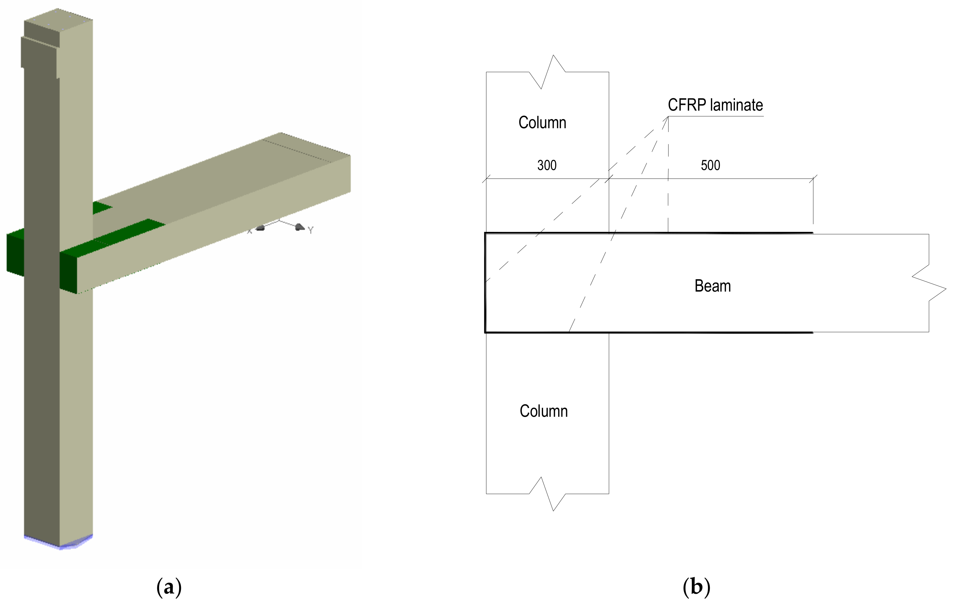
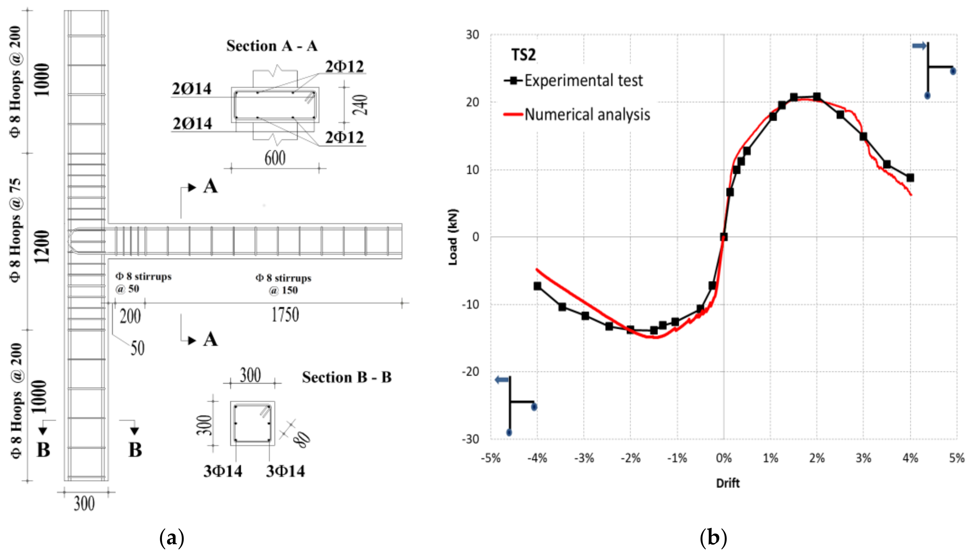
The specimen object of this study (
Figure 1a) is named TS2 and was designed with respect to seismic actions consistently with the Italian structural code [
28] considering a peak ground acceleration that equals a
g = 0.05 g (Seismic Zone 4), where a
g is the design ground acceleration for the life safety limit state (type A ground) [
29]. During the experimental tests the specimen was subjected to an axial load value equal to that due to gravity loads that is N = 290 kN (more details in [
25]).
From the modeling point of view, a classical smeared crack model was used to simulate the concrete features. The adopted main mechanical properties are as follows:
ft = 2.90 MPa,
f’c = 37 MPa,
ν = 0.2 and
Ec = 32.5 GPa, being respectively the tensile strength, compressive strength, Poisson ratio and elastic modulus. Compression stresses of concrete were simulated using a fictitious uniaxial model [
30] with a softening based on displacements [
21]. The tensile stresses of concrete are governed by an exponential crack opening law (tensile stress vs. crack opening displacement) based on the fracture energy (
Gf). The Remmel’s law [
31] allowed to compute a good fitting fracture energy value for the concrete under examination, being, however, a parameter with a wide range of variability [
20] as well as the concrete is highly variable inside RC constructions. For the steel stress-strain relations, an elastoplastic law with hardening having yielding stress equal to
fy = 480 MPa and failure stress of
fts = 590 MPa has been chosen. Finally, the CEB-FIP model code [
32] bond law was used to simulate bond slip behavior. Different laws were used depending on the bond and confining conditions of the beam rebars. More details in concerning the finite element modeling can be found in [
6].
Figure 1b reports the experimental and numerical skeleton curves. First of all, it is worth noting that the experimental behavior does not show a significant plateau due the slip phenomena, cracking of the beam near the column interface especially for those regions outside the column core, not confined by stirrups at all. Further, concrete crushing occurs very soon, contributing to the strength decay over 2% drift. It is worth noting that, despite the symmetry of the column and beam reinforcement, the load-drift envelopes are asymmetric in terms of load values. This is due to the different concrete cover sizes of bottom and top beam longitudinal reinforcement, that are 80 and 40 mm respectively. This was due to construction defects.
Even though numerical analyses were monotonic (two separate analyses for positive and negative loading), the load-drift curves predict very accurately the experimental patterns all over the range of drift values related to the experimental test. The post-peak branches are simulated very closely proving that choices and parameters of the nonlinear models were appropriate. More details regarding the numerical model can be found in [
6].
3. FRP Based Strengthening Intervention
The FRP-based intervention on the selected wide beam-column joint is designed with two basic aims. The first is getting an intervention arrangement fully compatible with the geometry and shape of the subassemblage. In fact, many similar studies consisted of testing strengthening interventions that appear not feasible in the real practice. This is due to the presence of the slab and of the spandrel beam that prevents the installation of FRP elements to strengthen the joint panel. The second aim is obtaining a strengthening configuration able to counteract the unfavorable damage mechanisms observed during the experimental tests on the as-built specimens. For these reasons, the configuration consisted of the application of two externally bonded unidirectional U-shaped CFRP (FRP based on carbon fibers) fabrics. They are glued with epoxy adhesive to the bottom and top faces of the beam as well as to the rear parts (vertical sides near the column) (see
Figure 2). This arrangement is fully compatible with external wide beam-column joints having a wide spandrel beam allowing the installation of the CFRP fabric on the bottom side. Moreover, this configuration can counteract the stresses caused by the pull-push effect of the beam rebars bent outside the column core also providing a beneficial confining effect to the concrete. It has been carefully avoided to put some strengthening elements on the vertical sides of the beam, as in reality, the spandrel beam and the slab are connected there.
Even though it is not accounted by the FEM model, it is good to be reminded that sharp edges of this arrangement should be rounded in practical applications to avoid stress concentrations, as suggested by codes and guidelines [
18].
In case a conventional spandrel beam (i.e., having the depth higher than the slab thickness) were present, the proposed strengthening configuration should be rearranged since the bottom laminate could not be connected with the vertical portions installed in the rear part of the beam. In a similar case, the connection between the bottom laminate and the vertical one should be realized using discrete CFRP strands passing through horizontal holes drilled in the spandrel beam.
The CFRP strengthening systems are usually in the form of lamellas that are prefabricated elements made of carbon fibers glued together with an epoxy matrix attached to the concrete substrate with an additional epoxy adhesive layer. Lamellas are more suitable for installations requiring straight alignment of composite material. In the case of applications presenting corners, as in this case, laminates are more appropriate since they easily overlap when necessary. Laminates are made by a unidirectional or multidirectional fabric of carbon fibers glued to the concrete by means of an epoxy adhesive that also covers the function of the matrix. This is the choice for the strengthening intervention object of this study.
The material used is commercially available and its mechanical properties are reported in
Table 1.
The idea of increasing the wide beam-column joint performance is very simple: shifting the weak section of the beam 300 mm from the intersection with the column. In this way, the maximum reaction at the beam end increases of 15% and the maximum load that the beam-column connection can carry gets a gain of the same order of magnitude. This latter means that the CFRP laminates should avoid the flexure failure of the beam in the first 300 mm near the column, being then, properly bonded. It is desirable, to provide a proper safety factor concerning the debonding failure mode, that the bond length must be larger than the effective bond length
Le. This latter is the value beyond which any increase in the bond length does not increase the ultimate strength of the bonded laminate. This is clearly stated in [
33] where also a simple formula to compute
Le is provided as follows.
where
Ef and
tf are the elastic modulus and the thickness of the laminate respectively, and
f’c is the concrete cylinder strength, assumed, as in [
6], equal to 37 MPa (derived by compressive tests on concrete cores extracted from the joint specimen). When computing the effective bond length for the present case, assuming the possibility of installing 1, 2 or 3 superimposed layers of laminates, the results in
Table 2 are obtained.
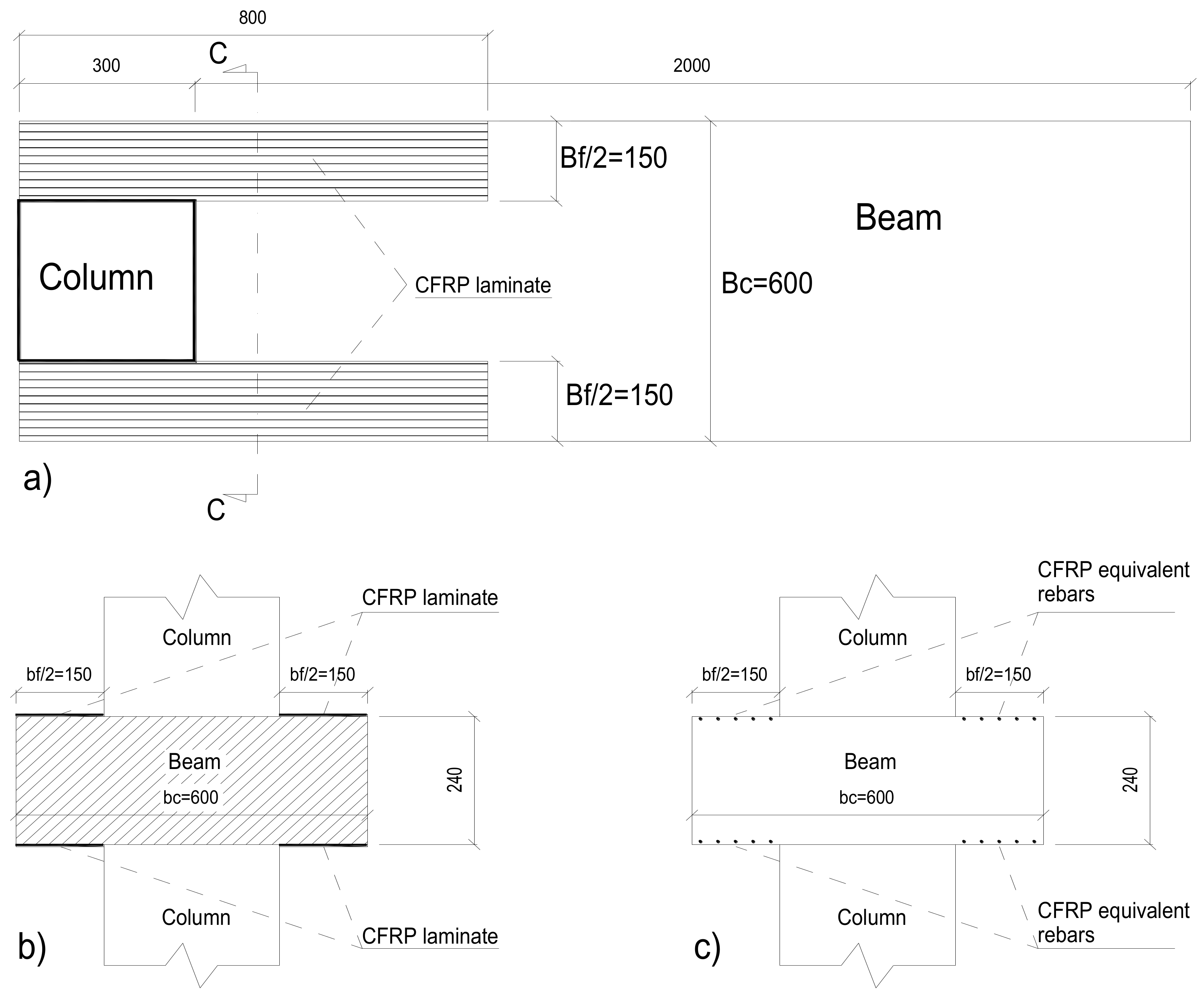
As can be seen from
Figure 2b, the CFRP laminate extends into the beam of 500 mm. Even though the bond length should not be larger than 124 mm, it was set equal to 200 mm as recommended by the Italian guidelines [
18]. For this reason, the CFRP laminates were extended 500 mm away from the beam-column intersection. Finally, some warnings should be highlighted regarding the appropriateness of this strengthening system. Increasing only the flexural strength of the beam can lead to weak column-strong beam mechanism which is detrimental to the structure’s global behavior. Moreover, the shear failure of the beam could happen. In the case under study, it was previously verified that these phenomena do not occur. Therefore, before applying such a strengthening technique, it is strongly suggested to check for possible other failure mechanisms that can occur before the beam flexural failure.
3.1. Modelling the FRP Laminate
Modelling the CFRP laminates externally bonded to concrete elements need to carefully take into account the material properties of the composite that is, usually, elasto-fragile [
22,
34]. ATENA 3D software offers several possibilities to do this. First of all, monodimensional truss elements could be used by making a discretization of the laminates’ width into several single truss elements. However, also 2D or 3D shell elements can be used by defining the fabric as a smeared reinforcement into these FE elements that are connected to the concrete substrate using so-called “interface elements” for which proper parameters must be defined in order to capture the possibility of CFRP laminates’ debonding.
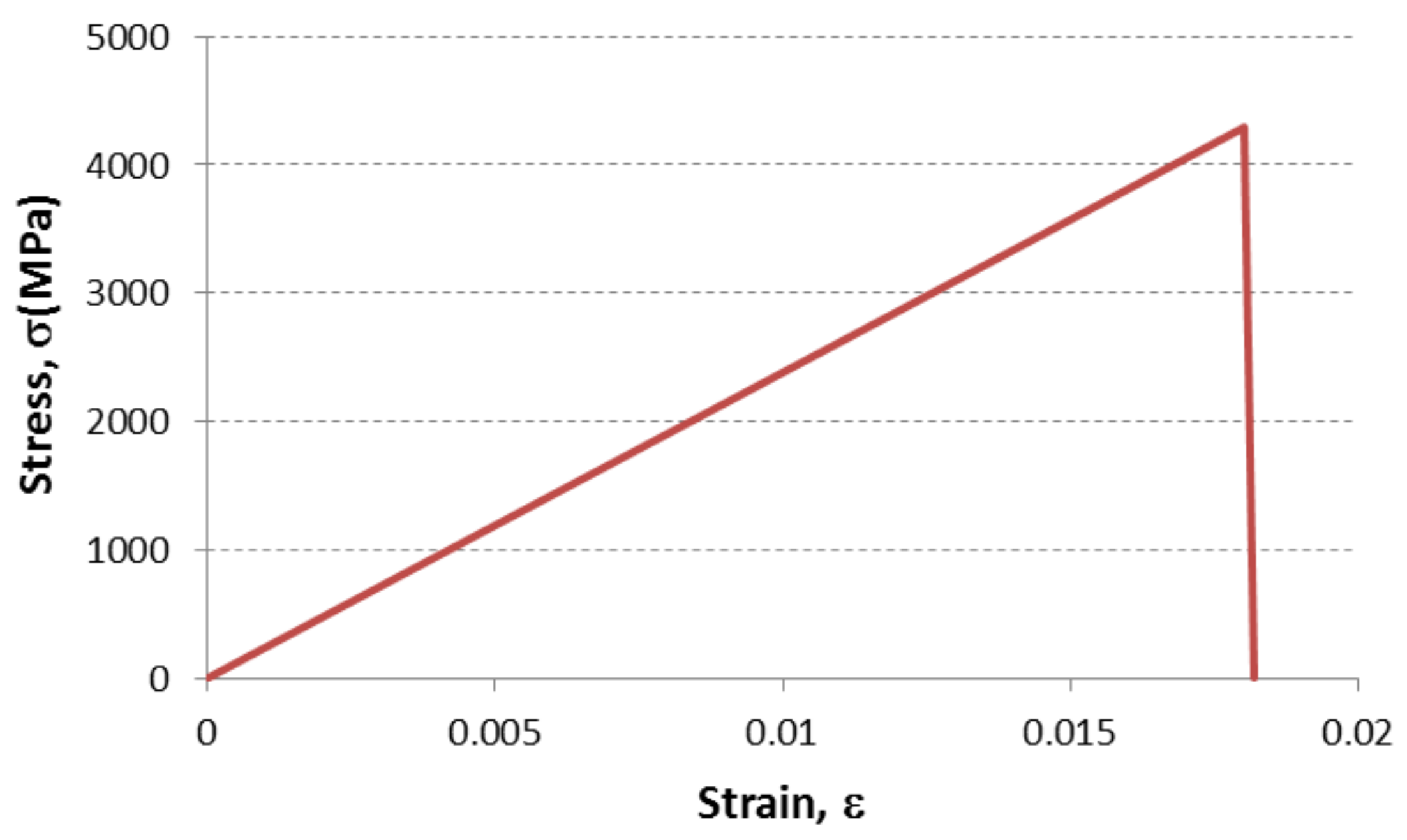
The most direct route to model unidirectional laminates is, perhaps, discretizing it into several truss elements able to absorb only axial loads, whose mechanical behavior is that of the fabric. This latter is an elasto-fragile material that can be modeled according to data reported in
Table 1, making reference to a material with a multilinear behavior belonging to the program library. The reinforcing area to be considered is
Af = 131 mm
2/m. The multilinear material for the FRP fabric reduces to a bilinear law as depicted in
Figure 3.
As can be noted, the softening branch of the stress-strain law of the fabric is not perfectly vertical. In fact, the ultimate strain value of the law has been obtained increasing the nominal strain value at fracture (see
Table 1) of 1/100 to avoid numerical issues.
The total area of each laminate (see
Figure 4) having a width equal to
is
.
Discretizing this area into five reinforcing bars (truss elements), each one equivalent to a laminate width of should have an area of with a diameter equal to .
These truss elements were modeled as laying just below the concrete surface to simulate as closely as possible the position of externally bonded CFRP laminates.
3.2. Modelling the FRP-to-Concrete Bond Behavior
The first studies in which detailed finite element software was used to model RC members strengthened with FRP systems always assumed perfect bond between concrete and composites [
14]. This is because the strength of adhesives is usually much larger than that of the concrete substrate. Chen and Teng [
33] built a database of single and double shear tests relevant to both steel and CFRP plates bonded to concrete. They found that in most cases the failure was due to the concrete fracture just below the interface between the plate and the concrete member. They also proposed a model for the determination of the ultimate load and highlighted the role of effective bond length. In fact, differently from steel bars embedded in concrete, increasing the bond length beyond the effective value does not increase the ultimate strength of the bonded plate.
In [
35], the researchers proposed FRP-to-concrete bond models. Using a meso-scale finite element model fitted on a database of 253 pull tests, they were able to develop local bond slip models with different level of complexity. In fact, taking into account those experimental tests, they demonstrated that debonding of FRP plates from concrete generally occurs in a thin layer of concrete with size ranging from 2 to 5 mm below the adhesive layer, they developed finite element models where the dimension of the finite elements near the concrete surface had a size one order of magnitude smaller than the fracture zone [
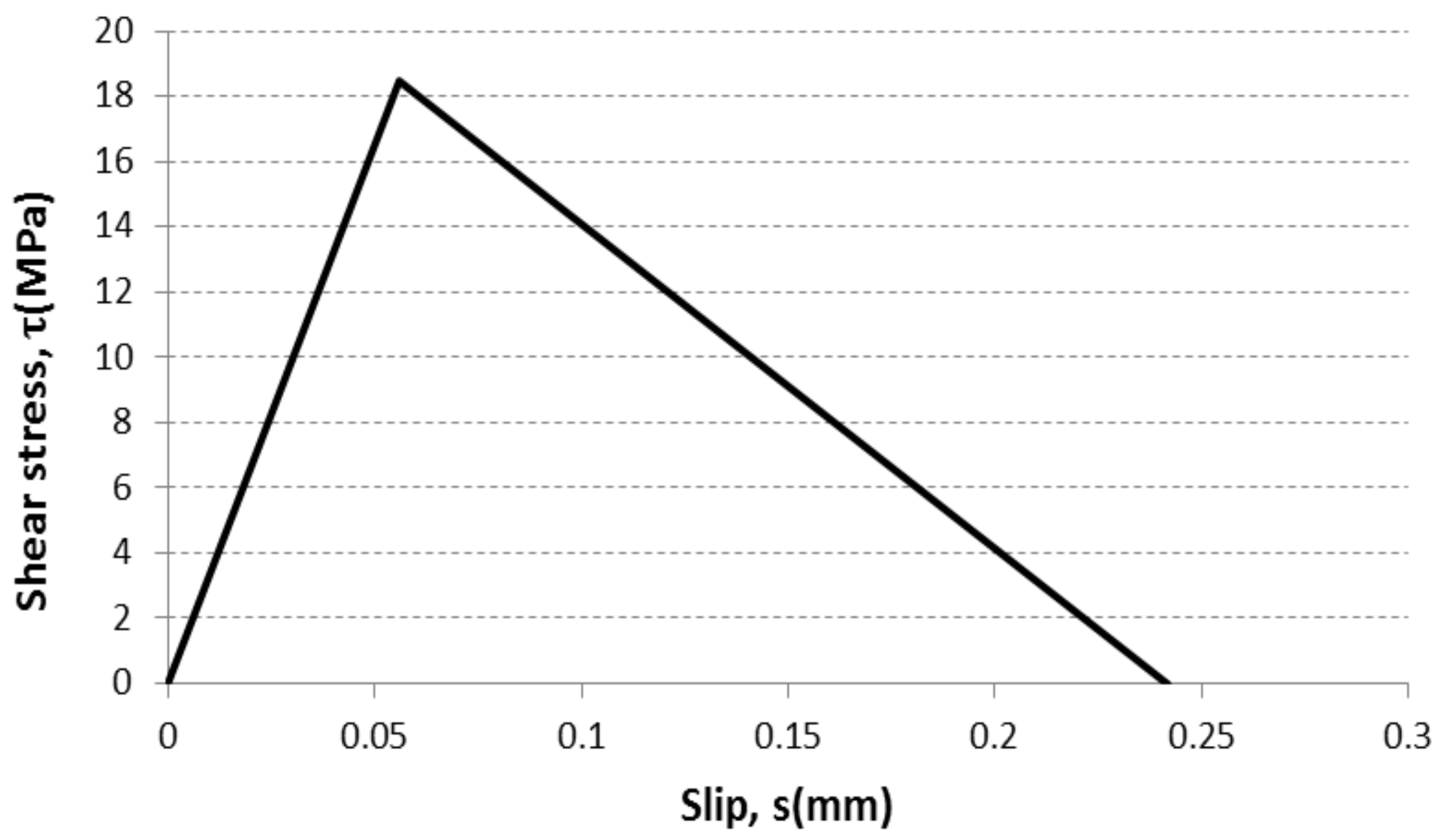
35]. In this study, their bilinear bond slip law is adopted due to its simplicity and practical effectiveness. This bond law has an ascending linear branch up to the ultimate stress value
τmax attained at a slip value of
s0 and a softening branch going to zero when the slip equals
sf. These three parameters are calculated as follows, assuming that the concrete substrate has a tensile strength equal to
ft = 2.9 MPa as assumed in the finite element models of the as-built specimen reported in [
6].
where
is the fracture energy computed as
and
depends on the width of the strengthened concrete element (the beam)
and that of the laminate
, computed as follows
This model fits very well a large database of shear tests of CFRP laminates externally bonded to concrete and is supposed to be appropriate for the intervention proposed in this study.
Modeling the calculated bond-slip behavior in ATENA 3D software is possible through the bond-slip law available for reinforcement bars. As can be seen in the study relevant to the as-built specimen [
6], bond laws were already used for the steel reinforcing bars. As the CFRP laminates are modeled as truss elements, they can be assigned a bond-slip law equivalent to that of
Figure 5. The main slip values are the same as calculated based on the Lu et al. bilinear law [
35] while the equivalent maximum bond stress
fb should be such that
giving
The parameters above mentioned were computed and reported in
Table 3.
Figure 5 displays the bond law used for the equivalent CFRP rebars.
4. Numerical Analyses in the Strengthened Condition
The numerical analyses were carried out with the same modalities used in the study made in [
6] by applying a monotonic loading displacement controlled at the top of the column. The total force applied was monitored along with the related displacement. The positive and negative loads were applied by means of two separate analyses differently from the experimental test that was cyclic and loads’ reversals were applied. The maximum top displacement considered was equal to 128 mm corresponding to a drift ratio of 4%, being the interstorey height equal to 3200 mm.
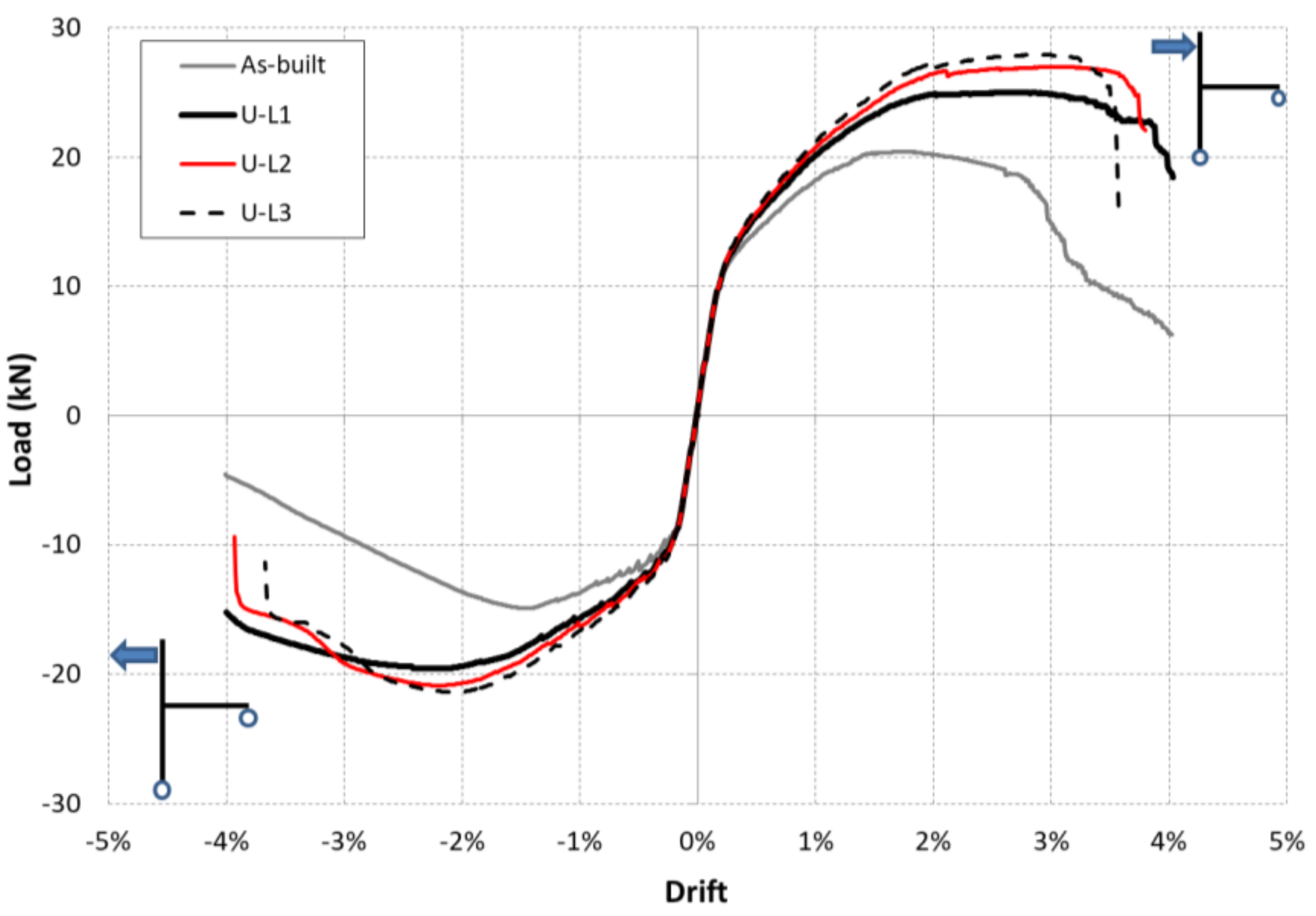
Figure 6 shows the comparison of load-displacement curves in the as-built condition as well in the CFRP-strengthened condition. This latter, assuming to have three different configurations corresponding to the application of one, two or three superimposed layers of CFRP laminates (e.g., curve U-L1 corresponds to the upgraded specimen with one layer of CFRP laminate, U-L2 two layers, and U-L3 three layers).
As can be seen, finite element analyses considering the CFRP strengthening system provide much better results in comparison with the as-built condition. Progressively higher loads are attained increasing the number of CFRP layers, although the behavior can be visually judged more fragile, as the load-displacement curve arrests earlier.
In
Table 4, the main parameters describing the seismic performance of the beam-column joint under examinations are reported. Positive and negative maximum values of loads (
Fmax and
Fmin), ultimate drift (
du+ and
du−) derived using the criterion of Panagiotakos and Fardis [
36] are reported. This latter, identifies the ultimate drift value as the one where a strength decay of 20% is observed with respect to the peak load. Moreover, yielding drift values are reported, as those where the FE model identifies the first yielding of the reinforcing bars. Finally, the displacement ductility is also reported, being the ratio
du/
dy.From data about the upgraded joints (U-L1, U-L2, U-L3), it can also be noted that the specimen object of these study, designed as belonging to a low seismicity zone (zone 4 on a seismic zonation of the Italian territory ranging from 1 to 4, where zone 1 is the most hazardous one) with peak ground acceleration a
g = 0.05 g (on type A soil), gets an increase in strength that shifts its performances to a level higher than a similar joint designed for seismic zone 2 (a
g = 0.25 g). This can be noted by comparing peak load values of the U joints with the TS3 specimen (designed for seismic zone 2) reported in [
6].
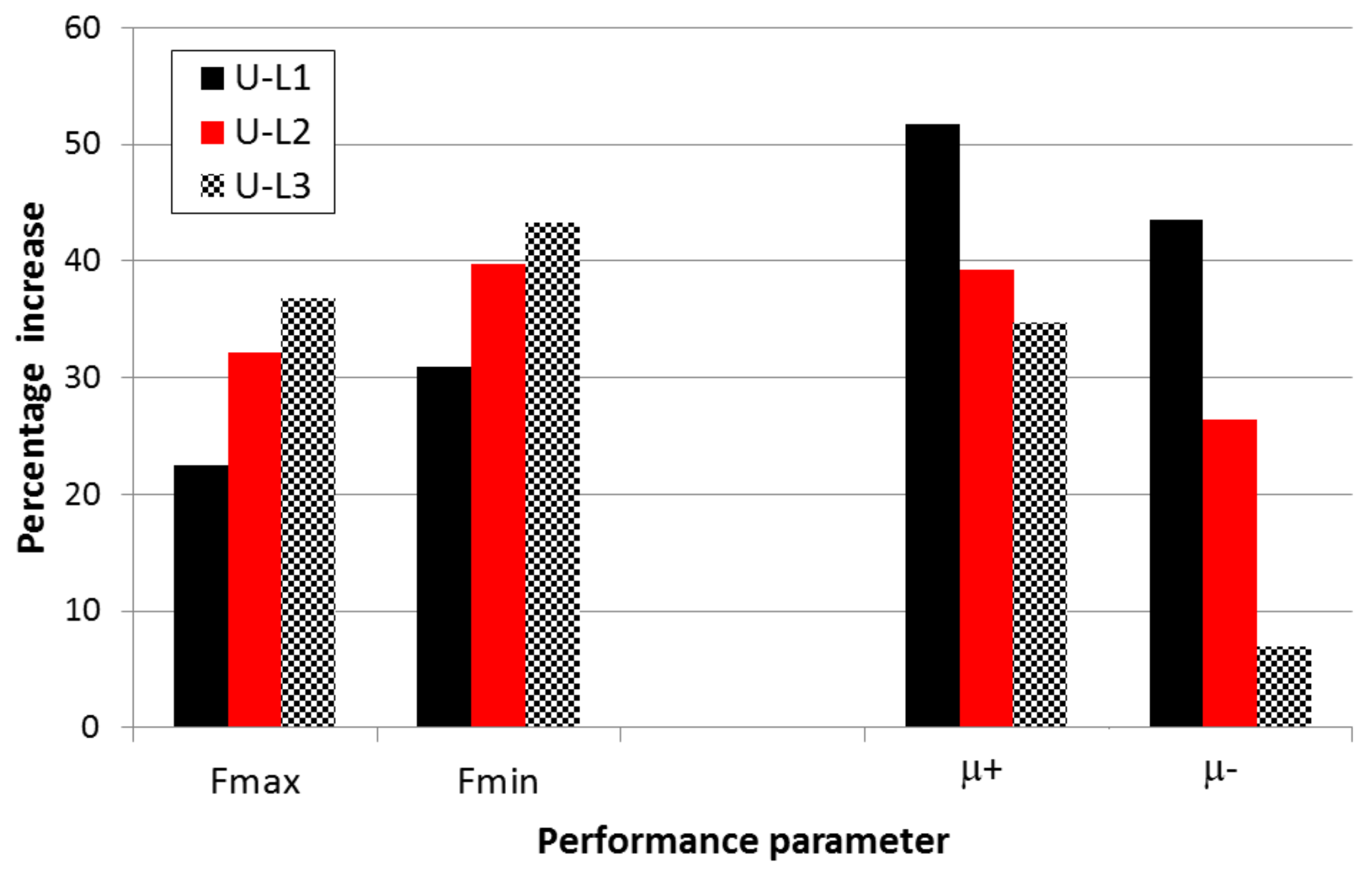
To visually compare performances of upgraded and as-built specimens, the graph of
Figure 7 can be usefully exploited. There, the main performance parameters (peak loads and ductility ratios) are reported as percentage increment with respect to the as-built specimen.
As can be seen, increasing the number of layers always increases the peak load response for positive and negative loads. The gain ranges between 22 and 37% for positive loading and between 30 and 43% for the negative one. The opposite outcome is found regarding ductility: the less is the number of CFRP layers the higher is the ductility increase. By using only one layer of laminates, the ductility increase is 51 and 43% for positive and negative loading respectively. These ductility gains reduce progressively when increasing the number of layers due to some FRP-to-concrete bond degradation near the ends of the U-shaped laminates (at about 500 mm distance from the column inner face) as well as to concrete crushing in the beam. With two CFRP layers (U-L2 specimen) they are 39 and 26%. Finally, with three laminates’ layers, the ductility gains are 35 and 7% for positive and negative loads respectively. For this reason, the upgrading intervention with three layers does not appear preferable for the case under examination, having the drawback of a lower ductility compared to the other solutions.
Indeed, problems related to debonding of FRP systems must be carefully accounted for, especially when the upgrading systems are devoted to increase the seismic strength of RC members or subassemblage, like in this case. In fact, debonding behavior can also be different from that derived by quasi-static shear test [
33] or from monotonic numerical analyses [
35]. Some further reduction of the FRP-to-concrete bond strength could occur when cyclic loading is applied as reported in [
37].
5. Damage Mechanisms
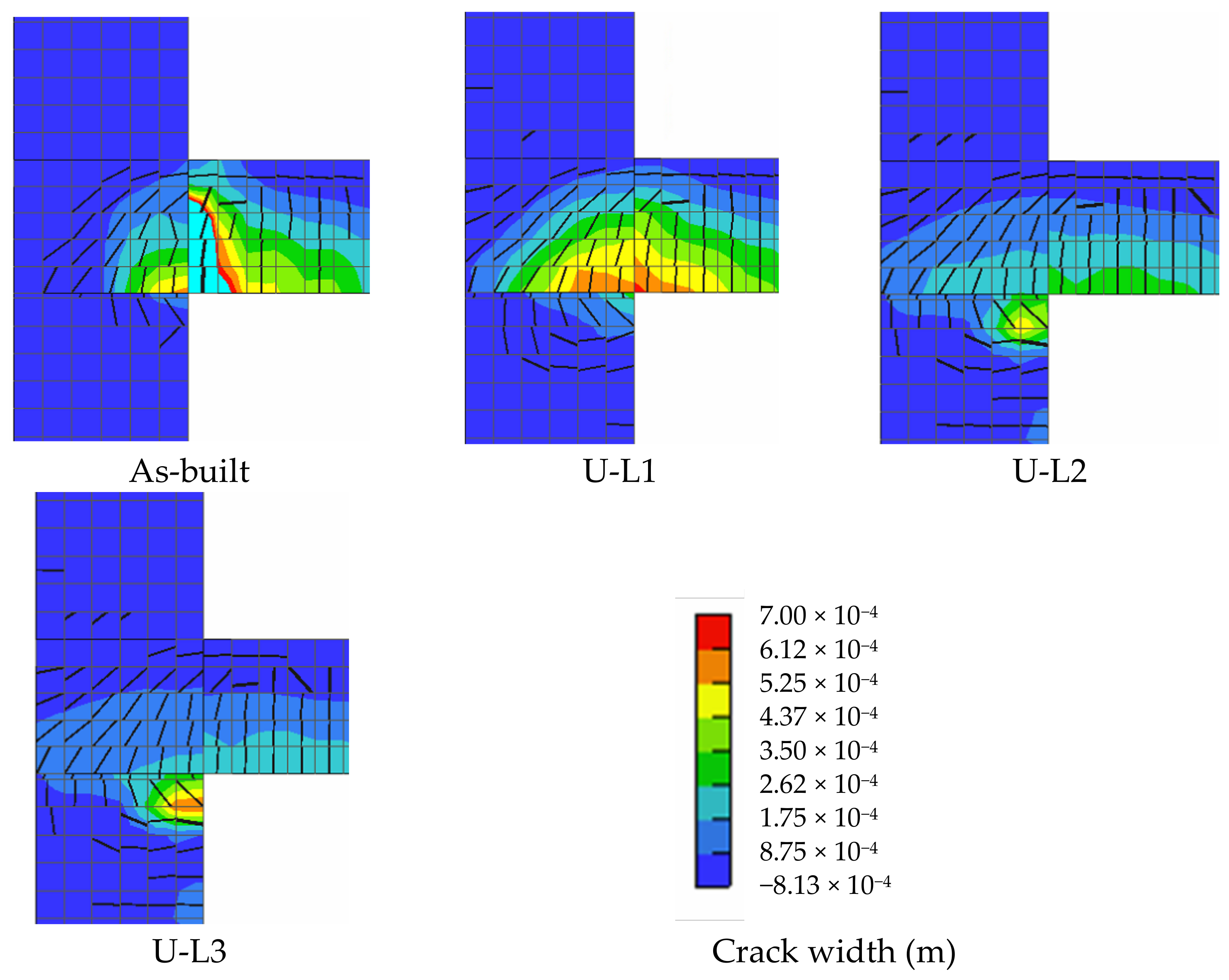
Like the as-built specimen, the collapse mechanism of the upgraded joints is weak beam-strong column since the flexural strength increment due to the CFRP intervention is not able to trigger the yielding of the column longitudinal bars. Comparison of crack patterns (for the sake of simplicity, only for positive loading) reported in
Figure 8 shows that the as-built joint experiences damage mainly in the beam-column intersection (with a large vertical crack where cyan area represents values out of scale) due to flexure along with damage in the surrounding regions. Upgraded joint specimens U-L1, U-L2 and U-L3 undergo a damage which has a lower crack width around the beam-column intersection, gradually shifting towards the column. In fact, the higher flexural strength of the beam spreads the column cracking that, however, does not yield. The confining effect provided by CFRP laminates results in smaller cracks in the beam sides included in the column width, although they are more diffuse.
The heavier damage to the column due to the increase of the flexural strength was also found in [
38] through experimental tests on similar beam-column joints carried out by applying steel upgrading systems. However, in a framework of Life Safety limit state, where structural damage is allowed, the performance of the CRFP specimens is remarkably better if compared to the as-built one, suggesting this kind of interventions is suitable for RC buildings equipped with wide beams and shallow spandrel beams.
6. Concluding Remarks
The research here presented is aimed at studying the seismic behavior of wide beam-column joints upgraded using CFRP laminates. This is made through numerical simulations based on finite element models previously calibrated to fit experimental tests performed at the Laboratory of Structures of the University of Basilicata. Specifically, the main aims of the study were related to develop an upgrading arrangement suitable for wide beam-column joints accounting for their peculiar geometry and to reduce the effects of degrading phenomena like bond slip of beam rebars and cracking of the beam sides at the intersection with the column.
The selected upgrading system consists of CFRP laminates provided with unidirectional fabric glued to the concrete substrate using epoxy adhesive, arranged in parallel to the beam longitudinal reinforcement.
Starting from finite element models previously calibrated to capture the behavior of an as-built wide beam-column joint specimen, the present study focused on the modelling modalities to account for the presence of the CFRP laminates accounting for the bond slip properties when they are glued to a concrete surface. Thus, the laminates were modeled as equivalent rebars with a proper bond-slip law, able to capture the behavior of the interface under shear loading. Three arrangements of the upgrading system have been investigated, that is the effect of one, two or three CFRP laminates’ layers was evaluated through FE analyses.
Finally, based on this comprehensive FE model, additional monotonic analyses on the upgraded joint model were carried out, finding out significant increases in the load carrying capacity but, even more remarkable, in the displacement ductility ratios especially with the lower number of laminates’ layers.
Significant increases were found for both positive and negative loads, remarkably improving the seismic performance of the as-built joint specimen. It is worth noting that as the strength increase with the number of laminates’ layers, the ductility decreases suggesting that the best solution are those with one or two layers depending on wanting more strength or ductility.
Based on the results of the numerical analyses the final crack patterns of the upgraded joint models were quite different from those ones of the as-built specimen resulting in a more diffuse damage but generally with a lower crack size. The damage shifted towards the column without causing its yielding. This damage condition in the upgraded joints appears completely allowable given that this kind of intervention is aimed at improving the seismic capacity of RC building concerning the Life Safety limit state.
Wide beam-column joints have been poorly studied so far, therefore this study is a first step towards the definition of more comprehensive upgrading strategies. Further research is needed to account for possible heavier debonding phenomena due to cyclic loading, and to evaluate how the upgrading solution here developed can be useful not only to improve performance at the Life Safety limit state but also to allow the repairability of the strengthened members in view of a more effective loss reduction in case of earthquakes.


