Article

Magnetic Materials: Novel Monitors of Long-Term Evolution of Engineered Barrier Systems

School of Geosciences, University of Edinburgh, Edinburgh EH9 3FE, UK
*
Author to whom correspondence should be addressed.
Geosciences 2016, 6(4), 54; https://doi.org/10.3390/geosciences6040054
Submission received: 30 August 2016 / Revised: 11 November 2016 / Accepted: 24 November 2016 / Published: 7 December 2016

Abstract

:
Most safety cases for the deep geological disposal of radioactive waste are reliant on the swelling of bentonite in the engineered barrier system as it saturates with groundwater. Assurance of safety therefore requires effective monitoring of bentonite saturation. The time- and fluid-dependent corrosion of synthetic magnets embedded in bentonite is demonstrated here to provide a novel and passive means of monitoring saturation. Experiments have been conducted at 70 °C in which neo magnets, AlNiCo magnets, and ferrite magnets have been reacted with saline (NaCl, KCl, CaCl2) solutions and alkaline fluids (NaOH, KOH, Ca(OH)2 solutions; pH = 12) in the presence of bentonite. Nd-Fe-B magnets undergo extensive corrosion that results in a dramatic change from ferromagnetic to superparamagnetic behaviour concomitant with bentonite saturation. AlNiCo magnets in saline solutions show corrosion but only limited decreases in their magnetic intensities, and ferrite magnets are essentially unreactive on the experimental timescales, retaining their initial magnetic properties. For all magnets the impact of their corrosion on bentonite swelling is negligible; alteration of bentonite is essentially governed by the applied fluid composition. In principle, synthetic magnet arrays can, with further development, be designed and embedded in bentonite to monitor its fluid saturation without compromising the integrity of the engineered barrier system itself.

Graphical Abstract

1. Introduction

One of the essential features of Geological Disposal Facility (GDF) concepts for the disposal of high-level radioactive waste in the deep sub-surface is the protection of radioactive waste canisters from corrosion in order to avoid, or at least minimize, the release of radionuclides into the near-field environment and beyond. To achieve this most Waste Management Organisations (WMOs) have developed safety cases based on the cumulative properties of multi-barrier systems. Such systems usually comprise the wasteform itself, the waste canister material, the overpack container (e.g., copper or stainless steel) in which a canister may be housed, the backfill and buffer materials that surround and support the canister/container and separate them from the surrounding rock into which the waste deposition chamber has been excavated, and the surrounding geological barrier or “geosphere”. The components of the multi-barrier system that are introduced into the excavated subsurface geology are collectively referred to as the Engineered Barrier System (EBS).
The material constituting the backfill, or near-field buffer, in the EBS is required to be chemically and thermally inert with respect to the material the canister is made of and with the surrounding geosphere. It is also required to possess a very low porosity and hydraulic conductivity so that fluid transport is minimized. Good sorption properties are also favoured, so that if any radioactive material is released into the near-field its dispersion is limited not only by the negligible hydraulic gradient but also by chemical fixation. For many GDF concepts the preferred backfill/buffer material is bentonite, a montmorillonite clay of the smectite series. The bentonite buffer in the Swedish KBS concept [1], for example, comprises a thick (1 m radius) cylindrical sleeve or ring around the waste canister/container. The compacted bentonite (density of 1.76 kg/m3), arranged to form a sleeve comprised of stacked rings of brick segments, swells considerably when it comes into contact with groundwater. This bentonite swelling property is central to the safety case for the GDF as it seals voids in the EBS and fractures present in the adjacent host rock disturbed during the excavation process, thereby forming a continuous, low-permeability medium around the waste packages following water saturation. This acts to limit the corrosion rates of the waste packages and the transport of any radionuclides or contaminants potentially released from corroded containers and then dissolved in groundwaters [2,3,4].
Monitoring of the GDF and its constituent parts is recognised internationally as being critical to decision-making during phased or staged disposal of radioactive waste [2,5,6,7,8]. Monitoring, via continuous or periodic observation and measurement, of the key thermal, mechanical, chemical, and hydrological parameters of a GDF is not only required in order to evaluate the behaviour of the repository system and performance of the barriers in relation to their safety functions, but also to build and sustain public confidence in geological disposal [4]. Indeed, monitoring is central to the European Community Seventh Framework Programme “Monitoring Developments for Safe Repository Operation and Staged Closure” (MoDeRn) Project [9] and to MoDeRn 2020 [10].
Whilst the need for pre-construction and operational monitoring of a GDF is fully accepted by all WMOs and national programmes in accord with the requirements of the International Atomic Energy Agency (IAEA) [8,11], the need for post-closure monitoring has until recently been questioned. One reason for this is that closure of a GDF would only occur once it is deemed, on the basis of all the pre- and operational monitoring coupled with forward modelling, to meet the standards required for post-closure safety. Another reason is that the maintenance of the monitoring systems cannot be guaranteed for durations beyond the accepted period of institutional control, perhaps a few hundred years. However, the European Commission (2004) has noted that there are likely to be societal pressures for monitoring for a period after repository closure in order to increase confidence in the evolution of the GDF system and our understanding of it. This recognition has led to the incorporation of ideas for post-closure monitoring into major projects concerned with GDF safety, such as MoDeRn [9] and MoDeRn2020 [8,10].
The challenge for monitoring at any stage of GDF construction, operation and closure lies in collecting the key physical and chemical parameters, such as stress fields, groundwater flows, thermal gradients, bentonite swelling, and void-loss, in the vicinity of the waste with as little impact on the integrity of the multi-barrier EBS as possible, whilst providing data of reliable quality over prolonged timescales [7,8,12]. These data must also be transmittable to the surface or at least distant analysis centres, so extensive research has been undertaken on wireless transmission networks and their coupling with remotely-sited sensing techniques such as microseismics, electric resistivity, acoustic emission, ultrasonic, gamma detection, and georadar. As all of these techniques require a power source in order to make measurements, their ability to monitor the parameters useful for the evaluation of EBS and near-field evolution beyond the local operational period and into the post-closure phase is limited. For example, electronic or electromagnet sensor devices that measure electrical resistivity, strain, and humidity or gas pressure can be emplaced within the bentonite buffer ring of the EBS and used to indirectly track bentonite re-saturation and swelling, but only for as long as their power sources last [7,12].
In order to extend the duration over which the EBS evolution, especially that of the bentonite buffer, can be monitored it is useful to consider alternative monitoring systems that do not require power at the sites of the sensors themselves. One approach to this is to embed in the EBS materials with diagnostic and measurable properties that change as the system evolves, thereby providing a proxy for its evolution, but which do not compromise the integrity of the EBS itself. This work describes and provides an initial evaluation of one such alternative approach to in-situ monitoring of any bentonite-based EBS using mineral or material magnets.

2. Materials and Methods

2.1. The Magnetic Monitoring Concept

Magnetic materials monitoring (MMM) focuses on utilising fluid-induced changes in the intrinsic magnetic properties of natural and synthetic materials to monitor the migration and recharge of fluids into the EBS of a bentonite-buffered GDF for high level waste.
The essential concept is to define suites of magnetic materials that react with fluids, or corrode, in predictable ways and in doing so change their magnetic properties in response to fluid ingress into the bentonite buffer situated around the waste packages. The time-resolved record of changes in magnetic properties then provides a passive, non-invasive monitor of how the EBS is re-saturating following back-filling, potentially both in terms of rates of fluid recharge and spatial variations in fluid ingress.
Magnetic monitoring is envisaged to be utilised initially to investigate fluid ingress on scales commensurate with single or multiple deposition sites as they are closed off (e.g., 5–10 ms lengthscales). Changes in magnetic signals are measured as time- and spatially-dependent deviations from the baseline values imposed by the magnetic materials embedded with the EBS measured near-site within the operational GDF. Such monitoring over the operational timescale of the GDF has the capacity to be complemented by longer-term magnetic monitoring from more remote magnetometer locations through upscaling of the system both spatially, with improvements in high-sensitivity magnetometers, and temporally through the use of successively less reactive magnets that corrode slowly and hence facilitate long-lived monitoring of the changes in magnetic signals beyond the operational phase of a GDF.

2.2. Magnetic Monitoring as a System

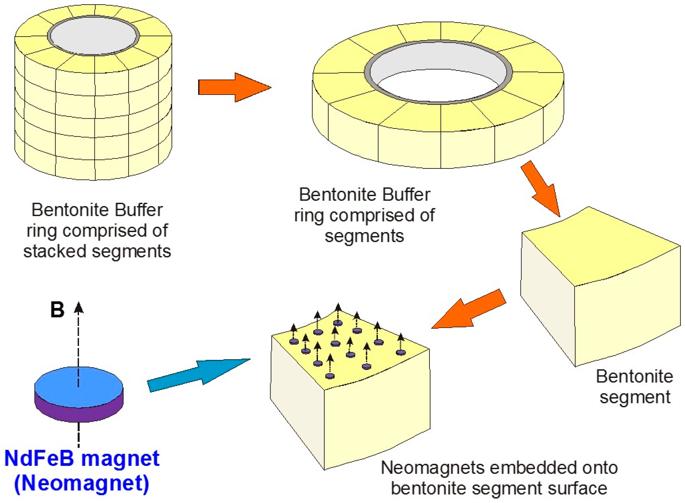
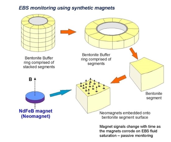
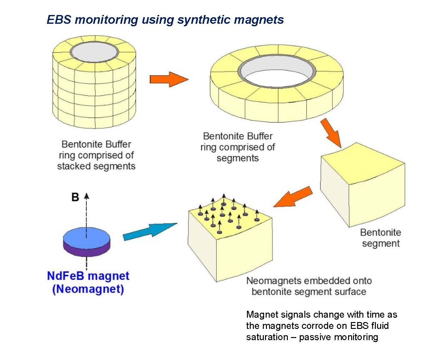
The principle of using magnets as a monitoring system is illustrated in Figure 1, which depicts a bentonite buffer “sleeve” located around an individual HLW (High Level Waste) canister and overpack, simplified from the Swedish KBS-3V (vertical waste deposition site) GDF design concept [1,13]. Using neodymium (Nd) magnets (“Nd-Fe-B magnets”) as an example, arrays of small, oriented magnets can be embedded on pre-pressed bentonite segments that have appropriately-sized depressions in their upper surfaces to accommodate the magnets without increasing void space. The example in Figure 1 has 12 such magnets embedded on one bentonite segment.
The magnets in this illustration are disc magnets with an axial magnetic field. If N45 grade Nd-Fe-B magnets are used the individual discs have residual flux density B fields (Br) of 1.29–1.35 Tesla, or 12,900–13,500 Gauss. Whilst full field and magnetic flux density modelling of the array of disc magnets effectively disposed in annular sheets around the canister is not the objective of this paper and is beyond its scope, the flux density at a point situated above the axis of an axially-magnetised cylindrical magnet can be calculated analytically [14,15,16] and used, with simplifying assumptions, to estimate the distance over which the magnetic signal produced by the system can be reliably measured. As modern ground-based and remote magnetometers can routinely measure with precisions of 0.1–1.0 nT (0.1–1 gamma), anomalies of the order of 10 nT are easily recorded and are assumed to provide a conservative lower limit of resolution for the method.
The flux density at a distance z axially above a magnetic rod or cylinder of radius R and thickness D, with characteristic residual flux density Br+, is given by the following equation [14]:
B(z) = (Br/2)[((D + z)/((R2 + (D + z)2)0.5)) − (z/((R2 + z2)0.5))]
Based on (1), a single N45 Nd-Fe-B magnet disc with radius of 20 mm and thickness 5 mm would produce an axial flux density of 10 nT at a distance of ca. 5 m immediately above the magnet, increasing to 100 nT at 2.4 m and 1000 nT at ca. 1 m. Whilst large and easily measurable as anomalies relative to the Earth’s field (ca. 50,000 nT), these flux densities are only present immediately above the single magnet, and decrease significantly laterally over only millimetres. In order to “spread out” the magnetic flux anomaly laterally or enlarge the effective axial region, a larger radius disc could be used or several disc magnets could be deployed and arranged to form a sheet or much larger radius disc-shaped array (Figure 1). At a very simplistic level, if it is assumed that the average Br for an array of disc magnets is proportional to the area of discs divided by the area of bentonite surface, then a 1.5 m radius planar array containing 100 discs each of 20 mm radius would result in an easily measurable flux density 1000 nT as far as 5 m axially above the array. The same calculation performed assuming a 0.5 m diameter magnet-free core inside a 1 m radius bentonite buffer ring leads to an estimate of 875 nT at 5 m above the magnet array plane in the canister/bentonite buffer deposition site.
Whilst the magnitudes of the axial flux densities estimated here are subject to order-of-magnitude uncertainties arising from the gross simplifications and assumptions used, they nevertheless indicate that an optimized design of permanent magnets embedded on planes within the bentonite buffer ring is capable of producing an initial magnetic field that can be measured remotely from within the operational GDF. Temporal changes (decreases) in the magnetic flux density caused by fluid-activated corrosion of the neo magnets during the progressive saturation of the bentonite EBS could be measured and used to monitor saturation provided the time-dependent corrosion behaviour of the magnets in contact with bentonite and realistic fluids is understood.

2.3. Experimental Program and Design

In this paper we present a distillation of the results of simple batch experiments involving magnets, bentonite, and fluids. The degradation of magnetic properties and signatures caused by fluid-induced corrosion of the different magnets are quantified to allow an evaluation of the sensitivity of magnetic monitoring with fluid ingress and saturation. We also summarise the effects of magnet corrosion on the bentonite matrix in order to understand if such corrosion might have a negative impact on the swelling properties of the bentonite buffer in a GDF [17].
Three types of synthetic permanent magnets (Grade N42 Nd-Fe-B, Grade 5 AlNiCo, and ceramic Ba0.6Fe2O3–Sr0.6Fe2O3 F30 ferrite), embedded in powdered MX80 Na-montmorillonite, have been reacted with three sets of solutions (Table 1), generating seven experiments for each magnet type in the presence of bentonite. We also have performed a set of experiments identical in terms of the magnets and solutions used but without bentonite (i.e., magnet-solution only experiments) in order to assess magnet corrosion in the absence of bentonite. The results of those experiments are not directly relevant to the behaviour of the bentonite-bearing EBS and hence will be reported elsewhere.
The experiments were run at 70 °C for 155 days each, and performed in tightly sealed 50 mL serum bottles with initial magnet:bentonite volume ratios of 1:19 and solids:solution ratios of 1:3.
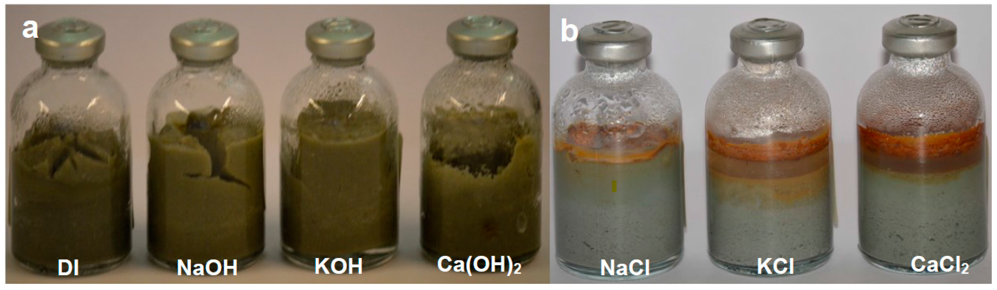
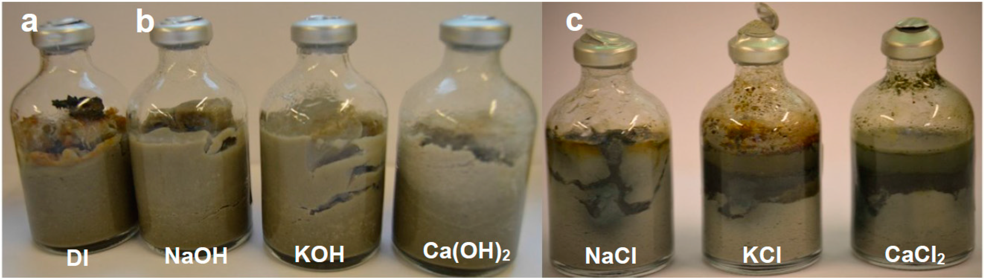
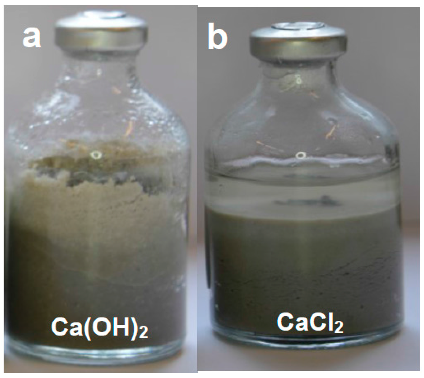
A temperature of 70 °C was chosen as it is regarded to be the average expected temperature affecting the EBS, taking into account the thermal gradient between the waste canister and the geosphere. The durations of the experiments were selected to allow measurable reaction to take place and enable comparisons to be made between them and with subsequent confined fluid flow experiments. The changes in magnet character (colour, state of aggregation) and bentonite swelling and colour was monitored for each experiment using photographs taken at monthly intervals prior to final extraction.
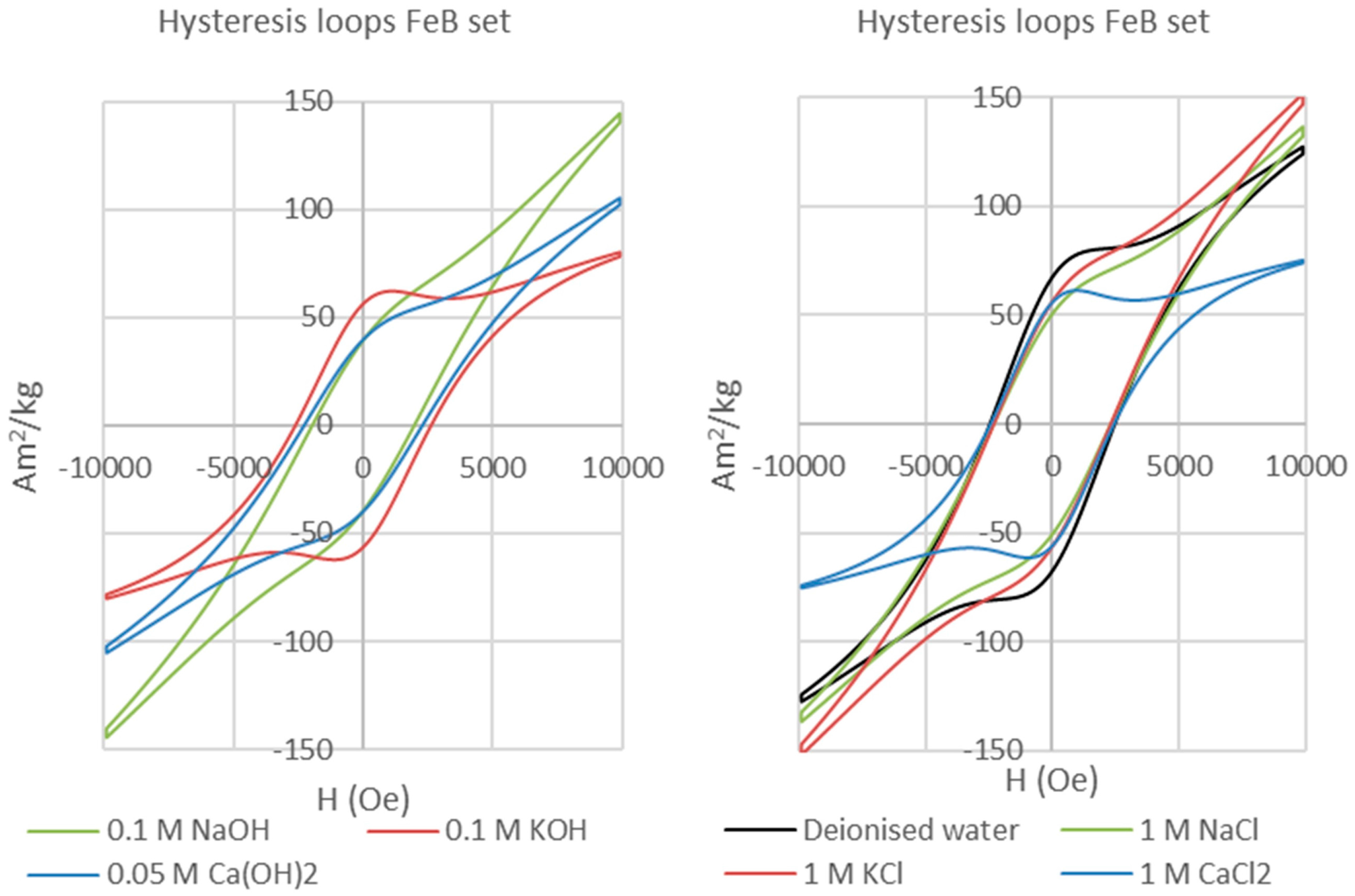
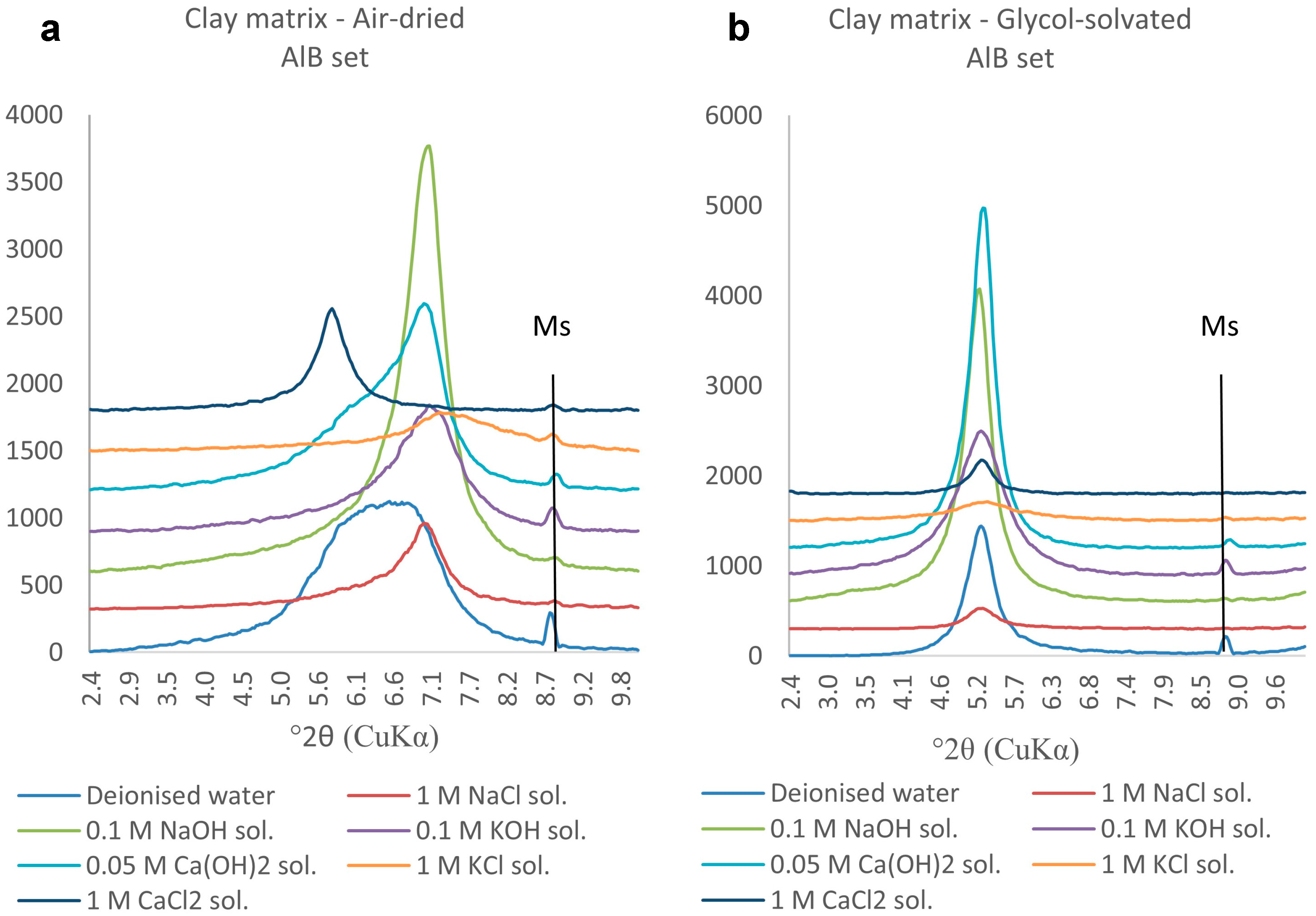
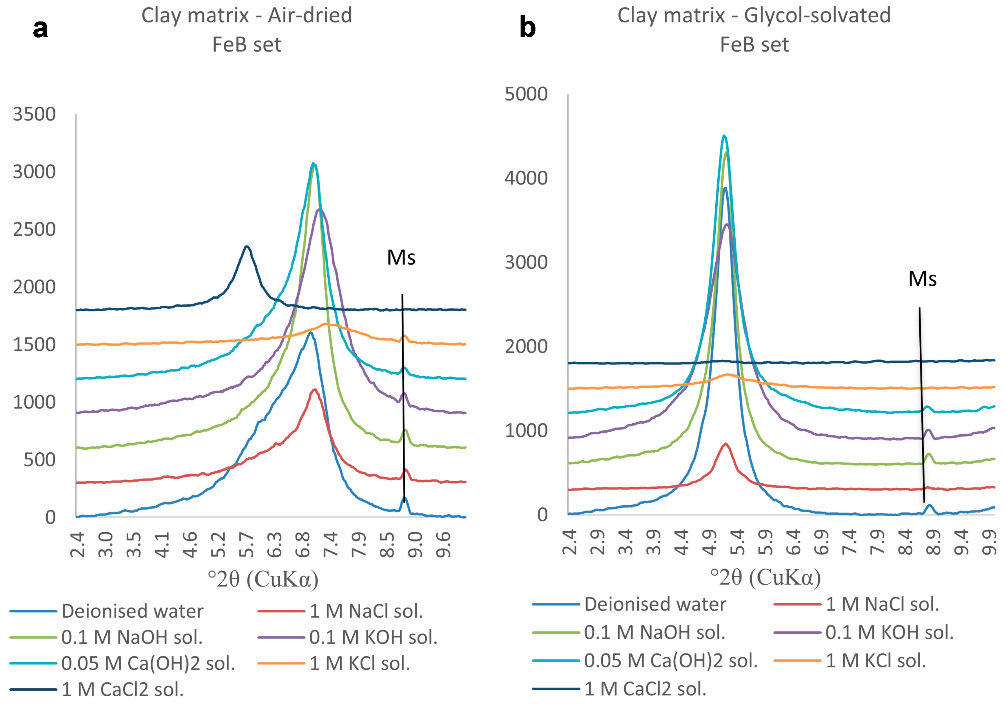
The bentonite clay matrix and the corroded permanent magnets were magnetically separated after each experiment. The clay matrix was analysed on oriented mounts with a Bruker D8 Advance diffractometer with Sol-X Energy dispersive detector (2–70° 2θ range, 0.025 step size, and 1.5 s step time). The magnetic analyses (hysteresis and backfield) were performed with a Princeton Measurements dual-head AGM/VSM (alternating gradient field magnetometer (AGM) / vibrating sample magnetometer (VSM); Princeton Measurements Corporation, Princeton, USA). Hysteresis (Ms—saturation magnetization, Mrs—remanence, and Hc—coercivity) and Backfield (Hcr—coercivity of remanence) parameters were calculated using the free software RockMagAnalyzer version 1.0 (Ludwig Maximilians Universität, München, Germany). Both hysteresis and backfield curves were fitted using log-Gaussian functions. Weights, hysteresis, and backfield values for the magnets are presented in Appendix A. The thermomagnetic analyses were performed with a Princeton Measurements dual-head AGM/VSM with high-T furnace applied (maximum temperature 790 °C) and in Argon atmosphere to prevent the oxidation of samples upon heating.
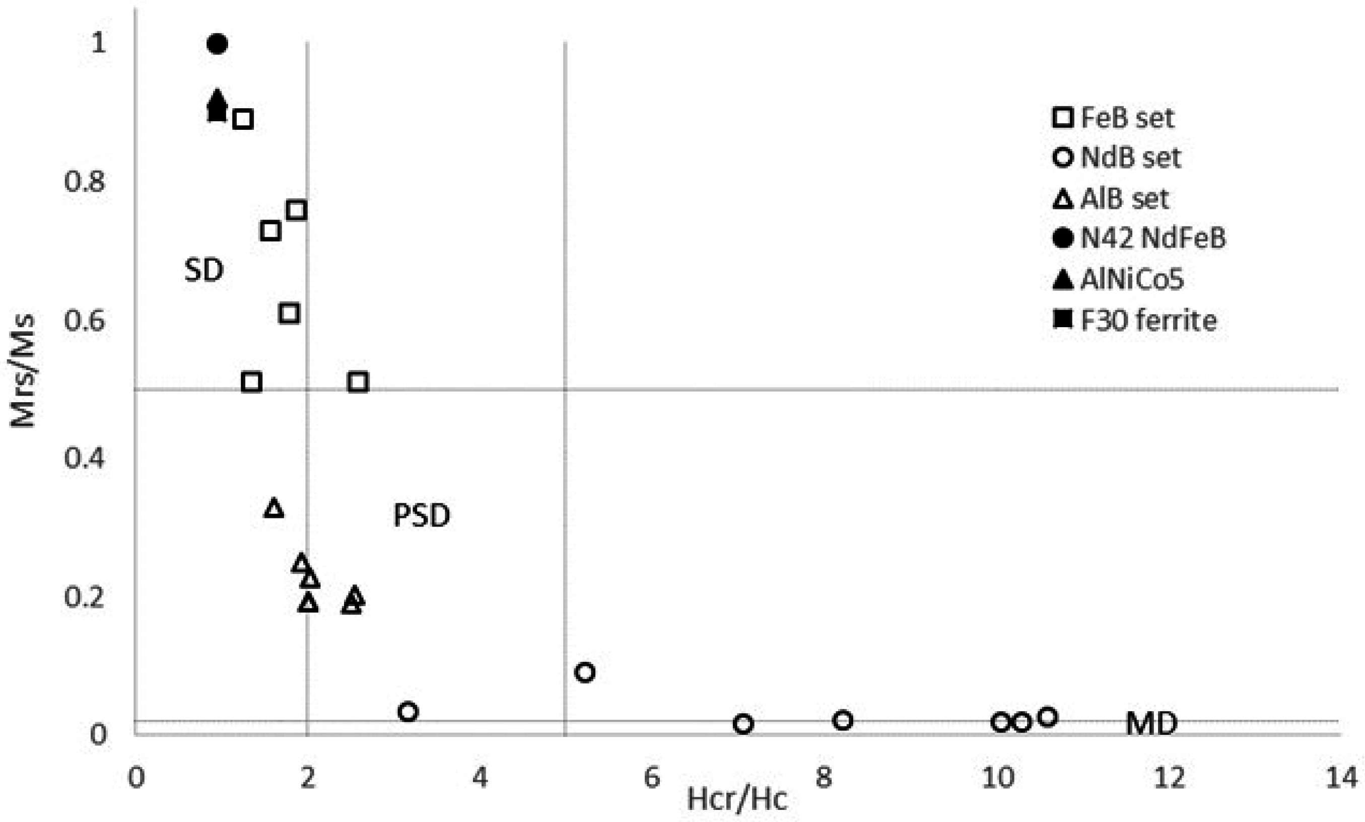
Following the studies of Day et al. [18] and Dunlop [19,20] on the grain size and compositional dependencies of the magnetic hysteresis properties of titanomagnetites and magnetites, a graphical approach using a plot of Mrs/Ms against Hcr/Hc was adopted in this work to analyse and classify the magnet behaviour and evolution.

3. Experimental Results

3.1. Magnet Behavior and Evolution

3.1.1. Nd-Fe-B Magnets (Nd2Fe14B Neo Magnets; NdB Set)

At the time of their extraction, the run products of the Nd-Fe-B (neo magnet/bentonite/fluids) experimental set exhibited striking differences in terms of corrosion of the magnetic phase, precipitation of corrosion-related phases, and colour of the bentonite matrix. The appearance of the neo magnet fragments differed depending on the type of fluid solution. In the samples treated with alkaline solutions the fragments were still intact and exhibited surface oxidation effects, whereas in the samples treated with the other two sets of solutions (saline solutions and deionized water) the magnets were completely disaggregated and the particles surrounded by micro-crystalline black material. The clay matrix did not show changes in colour for the samples reacted with alkaline solutions and deionized water, but in the samples reacted with saline solutions a halo of variable thickness was visible around the corroded magnets. The colour of this halo varied from a dark olive green at the magnet interface towards a light yellow/grey within the bentonite matrix (Figure 2).
The post-extraction hysteresis analysis of the Nd-Fe-B magnets shows a narrow loop with very low coercive field and remanence in the case of the sample reacted with 0.1M KOH solution, but superparamagnetic loops for all the other samples (Figure 3). The narrow, or “wasp-waisted” [21], hysteresis loop of the Nd-Fe-B magnet reacted in the KOH-rich solution is considered to be caused by the presence of several magnetic phases with different coercivities along with varied effective grain sizes [21,22]. Such wasp-waisted hysteresis loops reflect behaviour that is transitional between the single domain (SD) behaviour of the starting magnet and the superparamagnetic/multidomain behaviour of the most corroded magnets. The Nd-Fe-B magnet powder X-ray diffraction (PXRD) spectra indicate the formation of Nd-Fe-B hydrides, with hydrogenation of the main magnetic phase strongest in deionised water and saline solutions. This is responsible for major decreases in remanence and coercivity, and the complete loss of hysteretic properties. This interpretation is confirmed by comparison of Curie temperature measurements [23] with X-ray diffraction (XRD) crystal structure data for the corroded neo magnets (Figure 4), which demonstrates a strong correlation of mean hydrogens per formula unit (i.e., reaction and corrosion) with the Curie temperatures of the product Nd-Fe-B hydrides.
Powder XRD spectra demonstrate that the magnet corrosion is also characterised by the precipitation of Nd-Fe oxyhydroxides and hydroxides (e.g., Nd(OH)3) onto clay surfaces, causing the observed olive green haloes adjacent to the magnets.

3.1.2. AlNiCo Magnets (AlNiCo5 Grade LNG37; AlB Set)

At the time of their extraction, AlNiCo magnets treated with distilled water and alkaline solutions exhibited only weak oxidation of the magnet surfaces and pale colour haloes around the fragments embedded in the matrix (Figure 5a). All magnets were intact. Massive bentonite swelling (300% of the original starting volume) and the presence of tensile fractures typified these AlB (AlNiCo magnet/bentonite/fluids) experiments. In contrast, AlNiCo magnets from the AlB set of experiments involving saline solutions showed intense corrosion, marked by the precipitation of orange to red Fe-bearing secondary phases on the magnet surfaces or at the interface between the bentonite and saline solution, accompanied by a variation in the colour of the bentonite matrix (Figure 5b).
The hysteresis loops of the reacted AlNiCo alloy samples (Figure 6) are wider than those recorded for the neo magnet samples, consistent with a lower degree of reaction and corrosion. The loops are typical of pseudo-single-domain (PSD) magnetic materials.

3.1.3. Ferrite Magnets (F30: Ba0.6Fe2O3-Sr0.6Fe2O3; FeB Set)

Ferrites are well known for their high magnetic strength and their good performance even in humid or wet environments without the need for a surface coating. Our experiments confirm their resistance to corrosion for all the tested solution compositions at 70 °C in the presence of bentonite. In the experiments with alkaline solutions and deionized water Bentonite showed expansions of up to 300% from their initial volumes (Figure 7a), whereas swelling was limited for experiments with saline solutions (Figure 7b). In all cases, any bentonite alteration was undetectable. Even after 155 days no corrosion was observed on the ferrite magnets, which preserve very broad or bulging hysteresis loops indicative of the retention of single domain behaviour (Figure 8). Hence, ferrite magnets are not expected to react under the environmental conditions typical of a re-saturating GDF, although they may still be useful in longer term monitoring, and potentially could corrode in the presence of extreme composition or aggressive fluids that have not as yet been investigated.

3.1.4. Analysis of Magnetic Signatures

The key magnetic signatures of magnets from all experiments are depicted on the Day/Dunlop plot [20] of Figure 9. This plot allows discrimination of the domainal state of the magnets based on their hysteresis and backfield parameters.
Reacted ferrite magnets maintain square-shaped single-domain hysteresis loops (Figure 8) with high coercive fields and variable remanence values. The differences between samples simply reflect geometrical effects such as the shape of the fragments analysed, but nevertheless these run products all lie in the single-domain (SD) area of the Day/Dunlop plot (Figure 9), similar to the unreacted ferrite magnet and indicative of there being negligible corrosion. In contrast, the reacted AlNiCo magnets plot within the pseudo-single domain (PSD) field (Figure 9), showing a clear change from the single-domain initial AlNiCo magnet. This transition to PSD behaviour could reflect increasing domain strain related to the formation of corrosion products in or on the AlNiCo magnet.
Reacted Nd-Fe-B magnets scatter along a clear trend from the PSD field into the multi-domain (MD) field. Corrosion in this magnet type leads to the formation of a complex mixture of fine grained Nd-Fe-B hydrides around unreacted Nd-Fe-B [24,25,26,27], which leads to a net superparamagnetic behaviour (Figure 3) and precipitation of Nd and Fe oxyhydroxides adjacent to the corroded magnets. This produces the drastic decrease of the main hysteresis parameters observed in Figure 8, marking the transition from a magnetocrystalline-single-domain (SD) material to a superparamagnetic material (MD) with increasing corrosion from the unreacted magnet to the reacted alloy.
In their analysis of magnetites Day et al. [18] related decreasing coercivity to increasing magnetite grain size or to higher proportions of a “soft magnetic phase” in grain mixtures. The term “soft” magnetic material refers to a material which is easily magnetised (or demagnetised) and has a low coercive field. In this study the changes in the hysteresis behaviour of corroded Nd-Fe-B magnets from the truly single domain (SD) state typical of a “hard” ferromagnet, such as the unreacted Nd-Fe-B, to a multi-domain state are interpreted to be due to an increasing percentage of corrosion-related fine grained particles [28,29] with superparamagnetic behaviour. Under an applied magnetic field such particles will possess a randomised behaviour that resembles that of an increasing proportion of “soft” ferromagnets as described by [18,20].

3.2. Bentonite Response and Evolution

The clay matrix evolution in the NdB experiments has been addressed in [17], which showed that the clays in close contact with intensely corroded magnets reacted in saline solutions are characterised by weak and broad powder X-ray diffraction (PXRD) peaks that most likely reflect low-temperature dissolution/reprecipitation. Such broad and weak peaks are produced by a combination of fine particle size and poor crystallinity with complex or random interstratification within the clay. Hence the presence of Fe-bearing smectite as a weakly-crystallised phase at the clay-magnet interface could not be excluded. The clay transformations determined in the NdB experiments were all related to K-Na and Ca-Na cation exchange in the interlayer, and hence reflect only the initial solution composition and not the presence of the neo magnet.
The air-dried clay samples from the matrix of the AlB sets (Figure 10) feature clear 001 diffraction peaks centred at 7° 2θ (d001 = 12.5 Å, characteristic for Na-montmorillonite) in all samples except those reacted in the presence of CaCl2 or deionized water. The former is centred at 5.8° 2θ (d001 = 15 Å, characteristic of Ca-montmorillonite) and the latter shows a high but broad (flat-topped) diffraction peak that could indicate the presence of Fe-smectite. The sample reacted with the KCl solution shows a flatter peak with pronounced and broad right shoulder even after glycol-solvation, consistent with the presence of K-exchanged smectites. Upon glycol-solvation, all samples feature a shift of the 001 diffraction peak towards 5.2° 2θ, reflecting expansion of d001 to 17 Å and hence retention of the swelling properties required in a EBS.
The air-dried and glycol-solvated clay matrix samples collected in the FeB set (Figure 11) show the same behaviour as the samples from the AlB set (Figure 10). The pronounced left shoulders in the air-dried samples most likely reflect the presence of random interstratifications of Ca/K-exchanged swelling smectites and Na-montmorillonite. The sample reacted in 1 M CaCl2 solution shows a much flatter diffraction peak after glycol-solvation (Figure 10b) than the equivalent sample of AlB set (Figure 9b); this difference indicates the presence of more complex types of interstratifications involving Ca- and Na-montmorillonites.
In summary, the analysis of the bentonite matrix shows that the changes are mainly related to the initial composition of the solution rather than the presence and type of synthetic magnet. The principal changes, formation of Ca-montmorillonite (in Ca(OH)2 and CaCl2 solutions), or K-exchanged montmorillonite (in KOH or KCl solutions) do not have an influence on the overall swelling behaviour of the bentonite clay matrix. Some Fe-enrichment of the bentonite matrix in the surroundings of the magnets cannot be excluded [30], but any such Fe enrichment did not lead to the formation of non-swelling materials, such as chlorite, under the conditions investigated.

4. Discussion

The analyses of magnetic hysteresis and backfield properties on the reacted/corroded magnets allow the synthetic magnets to be classified according to their material-dependent reactivity:
  • Non-reactive permanent magnets. Grade F30 hexagonal ferrite did not exhibit corrosion-related precipitates or traces of oxidation. Consistent with this, their magnetic analysis (Figure 9) showed that all treated ferrites retained the single-domain properties of the initial material.
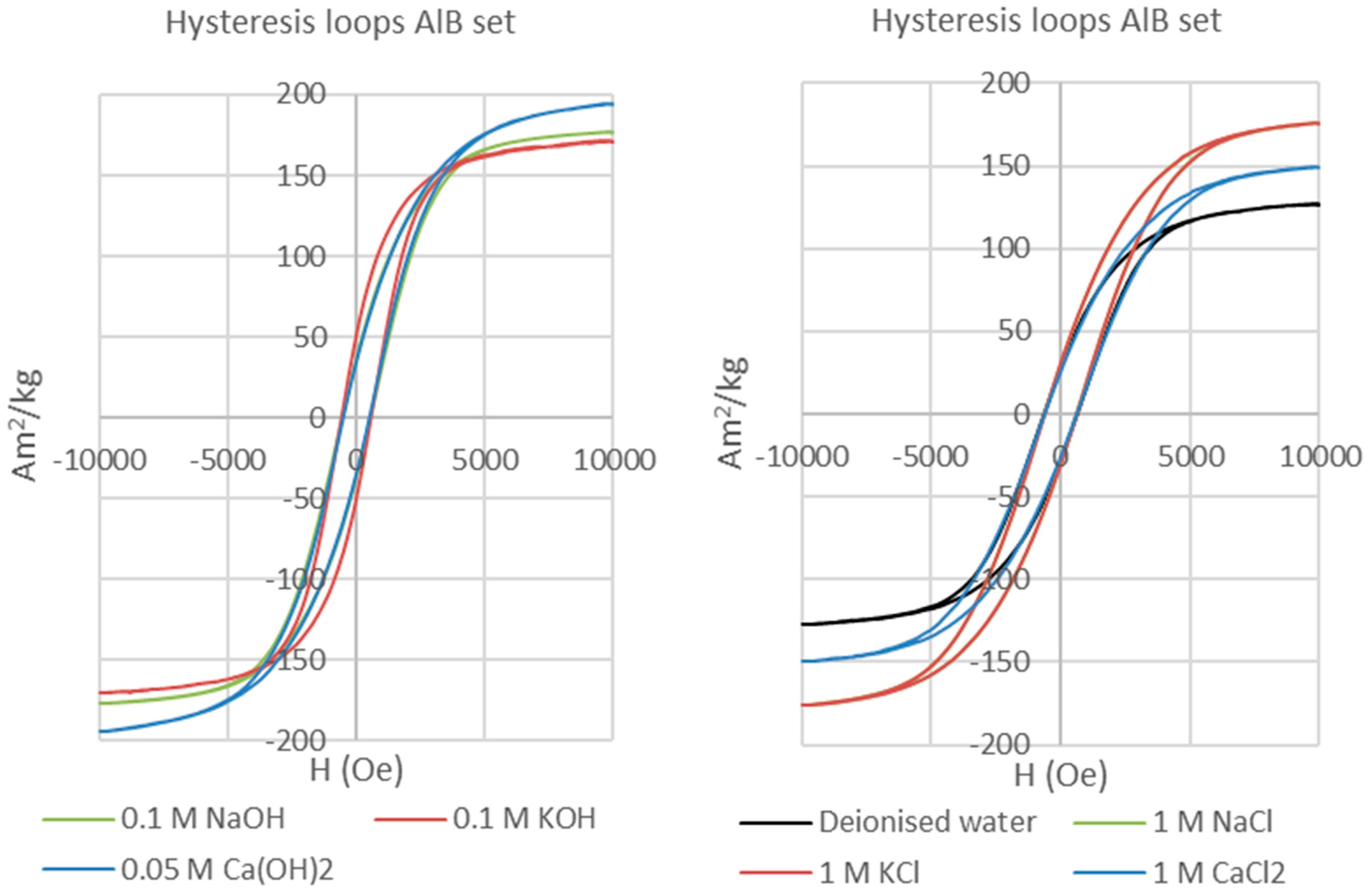
  • Weakly reactive permanent magnets. Grade 5 AlNiCo showed intense corrosion effects and associated precipitation of Fe/Al (oxyhydr) oxides when reacted with saline solutions, but the variations of the hysteresis and backfield properties were consistent in all treated samples and consistent with an evolution to pseudo-single domain magnetic state.
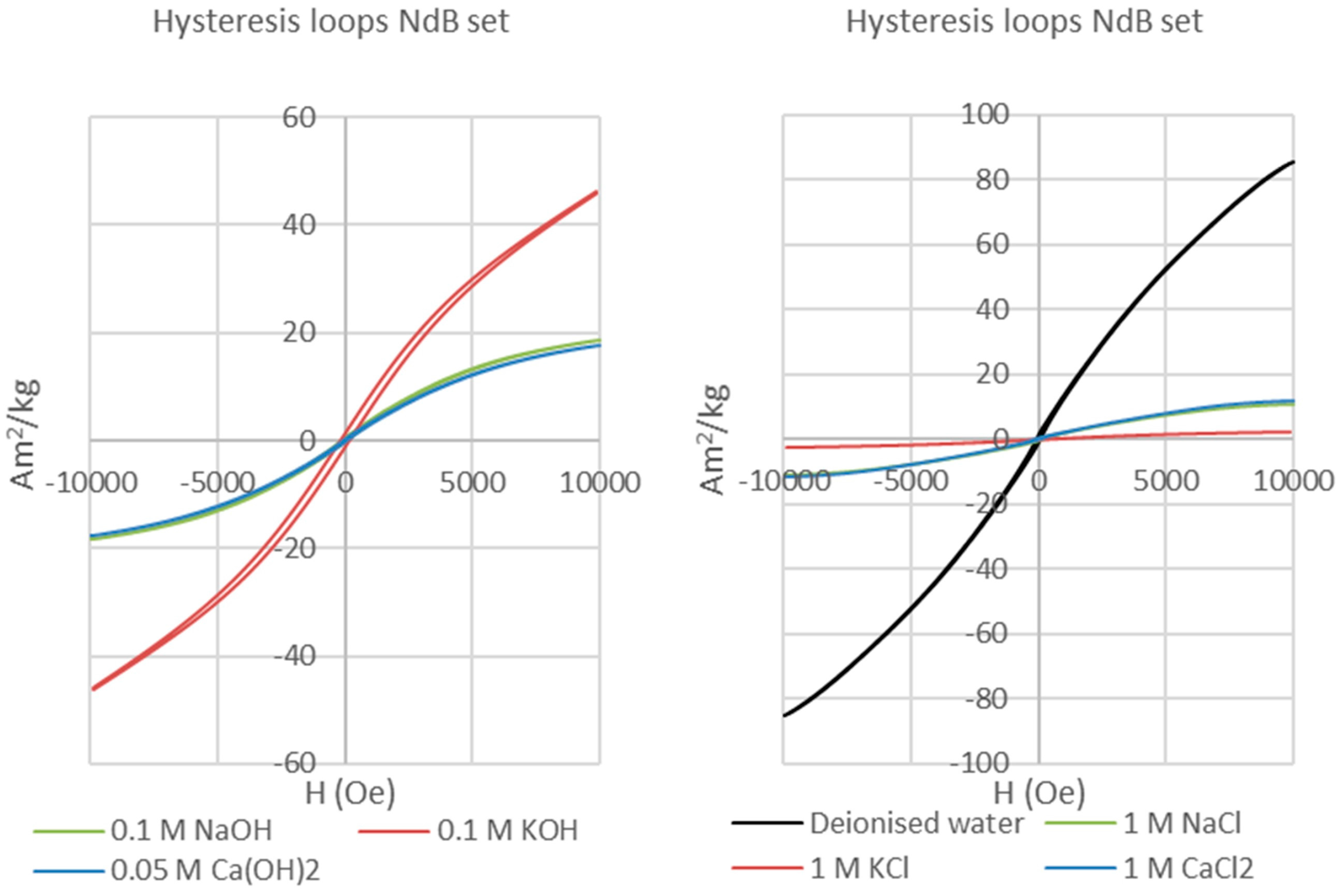
  • Highly reactive permanent magnets. Grade N42 Nd-Fe-B showed intense corrosion, marked by disaggregation of the fragments and precipitation of Fe and Nd (oxyhydr) oxides when reacted with saline solutions and deionized water, and oxidation and precipitation of Fe (oxyhydr) oxides when reacted in alkaline solutions. Magnetic hysteresis analysis demonstrated a clear transition from a single-domain starting material to superparamagnetic behaviour for the treated magnets.
These distinctive corrosion responses of the different magnets under different aqueous solution compositions and in the presence of bentonite indicate their considerable potential for magnetic monitoring of the re-saturation of bentonite-based EBS. The faster corrosion/alteration rates and marked decreases in magnetic coercivity observed for the Nd-Fe-B neo magnets indicate that these may be suitable for operational monitoring of fluid recharge and saturation in a GDF, whereas the less reactive AlNiCo magnets offer potential for longer-term monitoring, including post-closure monitoring. Ferrite magnets, which appear to be unreactive based on our experiments over durations of 155 days but could show reaction over longer timescales or in the presence of extreme fluids, may be useful in providing a baseline magnetic signal that can be registered by magnetometer arrays.
In the case of Nd-Fe-B neo magnets, comparison of the results of these experiments in the presence of bentonite with those for magnet-solution interactions alone [17] demonstrates that bentonite has a dramatic effect on magnet corrosion in the presence of saline water under static conditions (i.e., no or negligible fluid flow). In the absence of fluid flow, the presence of bentonite facilitates the development of two electric double layers with opposite polarity (one generated by the clay and the other by the corrosion on the magnet surface). This in turn causes enhanced corrosion of the magnets compared with the corrosion of the magnets in water alone [17]. This important electrical buffering effect provided by bentonite implies that experiments on neo magnet corrosion in humid environments or in the presence of fluids alone are unlikely to be relevant to magnet corrosion in an EBS once saturation commences.
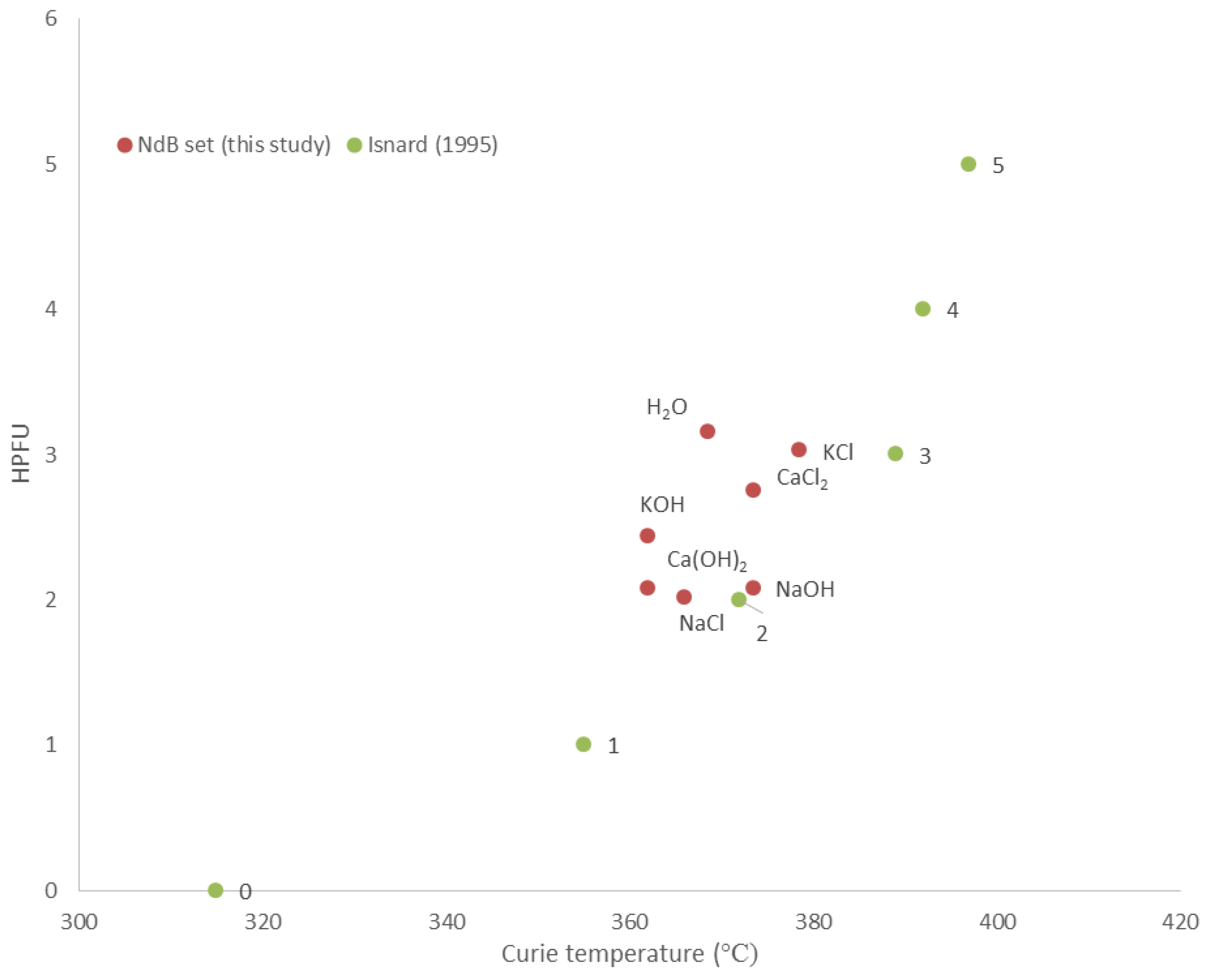
Conversely, the presence of magnets, whether reactive (neo magnets) or not (ferrites), is demonstrated to have a negligible effect on the swelling properties of bentonite. The insertion of reactive ferromagnets does not compromise the integrity of the EBS. Furthermore, the formation of Nd-Fe-B hydrides with an average hydrogenation state of 2–3 HPFU as the corrosion products of neomagnets places strong limits on the potentially deleterious evolution of H2 gas with corrosion where neo magnets are used as the monitoring materials. This means that magnets can be embedded in the bentonite, for example, on bentonite block surfaces (Figure 1), to form bespoke magnet arrays designed to optimise magnetic signal and sensitivity to fluid ingress. The design of such arrays could in principle be tuned to the geometry of the EBS (e.g., vertical vs horizontal or inclined deposition chambers) and the distance-sensitivity requirements of the magnetometer measuring system.

5. Conclusions

Neo magnets and AlNiCo magnets are corroded by saline and/or alkaline fluids in the presence of bentonite. Over time this leads to measurable degradation in their magnetic properties, such as their intrinsic magnetic field, that can serve as a proxy for saturation of the surrounding bentonite. Bentonite in these magnet-fluid-bentonite experiments at 70 °C shows negligible replacement by non-swelling clays and so retains the swelling property that is central to its role in ensuring the safety of the engineered barrier. Together, these results confirm the potential for the use of high-field synthetic magnets in pre-designed arrays to monitor EBS evolution and hence the safety case for deep geological disposal.
These results represent a positive starting point for Magnetic Materials Monitoring. Incorporation of this system into future GDF designs requires further development and testing of the method in two stages. Firstly, modelling of the initial signals produced by arrays of multiple magnets configured within the bentonite buffer is required in order to optimise array design for measurement of those signals at distances of metres to tens of metres. This modelling would also inform magnet array design for optimising sensitivity to change in signal with time as corrosion ensues and single domain ferromagnets transform to pseudo-single domain and multi-domain superparamagnetic materials. Secondly, the modelled multiple magnet system needs to be tested in up-scaled experiments, preferably within a URL (Underground Research Laboratory). These “proof of concept” tests would involve emplacement of the preferred magnet array in the bentonite buffer surrounding a heat source representing a spent fuel or high-level waste canister, set in the surrounding rock constituting the geosphere and engineered disturbed zone. This model deposition chamber, sealed off and artificially hydrated over time, would be instrumented with magnetometers to measure the evolution of magnetic signal with time, thereby monitoring EBS fluid saturation, and then sampled to test the modelling and magnetic analysis predictions.

Acknowledgments

This research has been supported by EPSRC consortium grant EP/I036427/1 “SAFE Barriers—a Systems Approach for Engineered Barriers” (2012–2016). This was co-funded by EPSRC and Nuclear Decommissioning Authority Radioactive Waste Management Directive, now Radioactive Waste Management (2012–2016). A. Muxworthy (Imperial College, UK) and O. Isnard (CRNS, Grenoble) are thanked for access to their laboratories for hysteresis and Curie Point measurements. Funding has not been provided to cover the costs to publish in open access.

Author Contributions

Simon Harley conceived the project and general experimental design; Nicola Rigonat and Ian Butler designed the experiments in detail; Nicola Rigonat performed the experiments and carried out all the materials characterization and data analysis; Ian Butler configured the experimental furnace; Simon Harley wrote the paper.

Conflicts of Interest

The authors declare no conflict of interest.

Appendix A

Table A1. Details of Magnetic Measurements.
AlNiCo ExptsAlB1AlB2AlB7AlB8AlB3AlB4AlB5
Weight (gr)0.0180.0340.060.0210.0380.0340.04
Ms (Am2)/kg117161167160172162137
Mrs (Am2)/kg29313852353126
Hc (mT)64 61 61 6154 56 50
Hcr (mT)120 152124 123 109 91 129
Ferrite ExptsFeB1FeB2FeB7FeB8FeB3FeB4FeB5
Weight0.0210.020.0350.0190.020.0440.02
Ms (Am2)/kg91779364827462
Mrs (Am2)/kg67397740506156
Hc (mT)246231231244197262228
Hcr (mT)387424415305507355423
Neo magnet ExptsNdB1NdB2NdB7NdB8NdB3NdB4NdB5
Weight (gr)0.0230.0250.0270.0270.0320.0250.02
Ms (Am2)/kg317.81117101.68.7
Mrs (Am2)/kg0.60.30.31.20.20.020.18
Hc (mT)5146.7108176
Hcr (mT)51434783879963

References

  1. Svensk Kärnbränslehantering AB (SKB). Buffer and Backfill Process Report for the Safety Assessment SR-Can; SKB Technical Report TR-06-1; SKB: Stockholm, Sweden, 2006. [Google Scholar]
  2. International Atomic Energy Agency (IAEA). Fundamental Safety Principles. IAEA Safety Standards for Protecting People and the Environment; Safety Fundamentals No. SF-1; International Atomic Energy Agency: Vienna, Austria, 2006. [Google Scholar]
  3. International Atomic Energy Agency (IAEA). Geological Disposal Facilities for Radioactive Waste; IAEA Safety Standards Series No. SSG-14; International Atomic Energy Agency: Vienna, Austria, 2011. [Google Scholar]
  4. Non-Disclosure Agreement (NDA). Geological Disposal: Near-Field Evolution Status Report; NDA: Harwell, UK, 2010. [Google Scholar]
  5. International Atomic Energy Agency (IAEA). Monitoring of Geological Repositories for High Level Radioactive Waste; IAEA-TECDOC-1208; International Atomic Energy Agency: Vienna, Austria, 2001. [Google Scholar]
  6. European Commission (EC). Thematic Network on the Role of Monitoring in a Phased Approach to Geological Disposal of Radioactive Waste; European Commission Project Report EUR 21025; European Commission: Luxembourg, Luxembourg, 2004. [Google Scholar]
  7. European Commission (EC). The Joint EC/NEA Engineered Barrier System Project: Synthesis Report (EBSSYN); Final Report—No. EUR 24232; European Commission: Luxembourg, Luxembourg, 2010. [Google Scholar]
  8. International Atomic Energy Age (IAEA). Monitoring and Surveillance of Radioactive Waste Disposal Facilities; IAEA Safety Standards Series No. SSG-31; International Atomic Energy Age: Vienna, Austria, 2014. [Google Scholar]
  9. European Commission (EC). MoDeRn Workshop on Monitoring Technologies (Troyes), Deliverable D-2.2.1, October 2010; European Commission: Luxembourg, Luxembourg, 2010. [Google Scholar]
  10. Implementing Geological Disposal Technology Platform (IGDTP). Modern2020. Available online: http://www.igdtp.eu/index.php/european-projects/modern2020 (accessed on 28 November 2016).
  11. International Atomic Energy Agency (IAEA). Geological Disposal of Radioactive Waste. IAEA Safety Standards for Protecting People and the Environment; Safety Requirements No. WS-R-4; International Atomic Energy Agency: Vienna, Austria, 2006. [Google Scholar]
  12. Implementing Geological Disposal Technology Platform (IGDTP). Implementing Geological Disposal of Radioactive Waste—Technology Platform; Presentations and Outcomes: Kalmar, Sweden, 2014. [Google Scholar]
  13. Svensk Kärnbränslehantering AB (SKB). Design Premises for a KBS-3V Repository Based on Results from the Safety Assessment SR-Can and Some Subsequent Analyses; SKB Technical Report TR-09-22; SKB: Stockholm, Sweden, 2009. [Google Scholar]
  14. Zhilichev, Y. Calculation of magnetic field of tubular permanent magnet assemblies in cylindrical bipolar coordinates. IEEE Trans. Mag. 2007, 43, 3189–3195. [Google Scholar] [CrossRef]
  15. Babic, S.; Akyel, C. Improvement in the analytical calculation of the magnetic field produced by permanent magnet rings. Prog. Electromagn. Res. C 2008, 5, 71–82. [Google Scholar]
  16. Ravaud, R.; Lemarquand, G.; Lemarquand, V.; Depollier, C. Analytical calculation of the magnetic field created by permanent-magnet rings. IEEE Trans. Mag. 2008, 44, 1982–1989. [Google Scholar] [CrossRef]
  17. Rigonat, N.; Mavris, C.; Harley, S.L.; Butler, I.B. Monitoring water-chemistry evolution in the bentonite buffer using magnets: Effects of corrosion on buffer stability. Clay Min. Soc. Works. Lect. Ser. 2016, 21, 231–240. [Google Scholar]
  18. Day, R.; Fuller, M.; Schmidt, V. Hysteresis properties of titanomagnetites: Grain-size and compositional dependence. Phys. Earth Planet. Int. 1977, 13, 260–267. [Google Scholar] [CrossRef]
  19. Dunlop, D. Magnetism in rocks. J. Geophys. Res. 1995, 100, 2161–2174. [Google Scholar] [CrossRef]
  20. Dunlop, D. Theory and application of the Day plot (Mrs/Ms versus Hcr/Hc). 1. Theoretical curves and tests using titanomagnetite data. J. Geophys. Res. 2002, 107. [Google Scholar] [CrossRef]
  21. Roberts, A.P.; Cui, Y.; Verosub, K.L. Wasp-waisted hysteresis loops: Mineral magnetic characteristics and discrimination of components in mixed magnetic systems. J. Geophys. Res. 1995, 100, 17909–17924. [Google Scholar] [CrossRef]
  22. Bennet, L.H.; Della Torre, E. Analysis of wasp-waisted hysteresis loops. J. Appl. Phys. 2005, 97, 10E502. [Google Scholar]
  23. Isnard, O.; Yelon, W.; Miraglia, S.; Fruchart, D. Neutron-diffraction study of the insertion scheme of hydrogen in Nd2Fe14B. J. Appl. Phys. 1995, 78, 1892–1898. [Google Scholar] [CrossRef]
  24. Rupp, B.; Resnik, A.; Shaltie, D.; Rogl, P. Phase relationship and hydrogen absorption of neodymium-iron-(boron) alloys. J. Mat. Sci. 1988, 23, 2133–2141. [Google Scholar] [CrossRef]
  25. Chang, K.; Warren, G. The effect of absorbed hydrogen on the corrosion behavior of NdFeB alloys. IEEE Trans. Mag. 1995, 31, 3671–3673. [Google Scholar] [CrossRef]
  26. Schultz, L.; El-Aziz, A.; Barkleit, G.; Mummert, K. Corrosion behavior of Nd-Fe-B permanent magnetic alloys. Mat. Sci. Eng. 1999, 267, 307–313. [Google Scholar] [CrossRef]
  27. Yang, H.; Mao, S.; Song, Z. The effect of absorbed hydrogen on the corrosion behavior of sintered NdFeB magnet. Mater. Corros. 2012, 63, 292–296. [Google Scholar] [CrossRef]
  28. Christodoulou, C.; Schlup, J.; Hadjipanayis, G. Oxidation of Fe-R-B powders during preparation of permanent magnets. J. Appl. Phys. 1987, 61, 3760–3762. [Google Scholar] [CrossRef]
  29. Nothnagel, P.; Muller, K.-H.; Eckert, K.; Handstein, A. The influence of particle size on the coercivity of sintered NdFeB magnets. J. Mag. Mag. Mater. 1991, 101, 379–381. [Google Scholar] [CrossRef]
  30. Marty, N.; Fritz, B.; Clement, A.; Michau, N. Modelling the long term alteration of the engineered bentonite barrier in an underground radioactive waste repository. Appl. Clay Sci. 2010, 47, 82–90. [Google Scholar] [CrossRef]
Figure 1. The essence of the MMM (Magnetic Monitoring Materials) concept. Yellow segments form the bentonite buffer ring/sleeve in the HLW (high level waste) EBS (engineered barrier system). Orange arrows join the parts of this from the larger scale (full segmented sleeve, 1.5–2 m radius) to the scale of a single bentonite segment, both without and with embedded magnets (Nd-Fe-B magnets in this example). The blue disc is a magnified view of a single axially magnetised N42 Nd-Fe-B magnet.
Geosciences 06 00054 g001
Figure 2. Post-extraction picture of the samples of NdB set. (a) For the sample reacted in deionized water the magnet has been pushed upwards by the swelling bentonite matrix and there is the presence of precipitated orange-coloured material; (b) The three samples reacted in alkaline solutions show maximum clay swelling, tensile fractures, and no reaction haloes; (c) The three samples reacted in saline solutions feature partially swollen matrix and the presence of black-coloured material precipitated at the solution/bentonite interface. The butyl septa are deformed and swollen, indicating the presence of hydrogen gas formed by the corrosion of the magnets.
Geosciences 06 00054 g002
Figure 3. Hysteresis loops (magnetisation vs applied field) of NdFeB permanent magnets reacted with alkaline solutions (left), deionised water (right), and saline solutions (right). The sample reacted with a KOH solution features a slightly wider hysteresis loop, typical of a pseudo-single domain material, whereas all other hysteresis loops show the classic “wasp-waisted” shape of a superparamagnetic material.
Geosciences 06 00054 g003
Figure 4. HPFU (hydrogens per formula unit) vs. Curie temperature plot. The samples of the NdB set, in which HPFU has been calculated from powder X-ray diffraction (PXRD) spectra, are plotted and compared with pure NdFeB hydrides (Isnard, 1995 [23]: points 0, 1, 2, 3, 4, and 5). The relative scatter of the samples from this study reflects their impure chemical compositions which causes shifts in temperature.
Geosciences 06 00054 g004
Figure 5. Post-extraction picture of the samples of AlB set. (a) Samples reacted with deionized water and alkaline solutions, showing complete swelling of the bentonite matrix, with formation of tensile fractures; (b) The three samples reacted with saline solutions, showing abundant quantities of red/orange precipitates at the solution/air interface and at the solution-bentonite interface. The bentonite matrix is not completely swollen and presents an orange colour at the interface, gently fading towards a yellow/pale-olive-green colour towards the basal part of the matrix.
Geosciences 06 00054 g005
Figure 6. Hysteresis loops of AlNiCo permanent magnets reacted with alkaline (left) and saline (right) solutions. All have a pseudo-single-domain behaviour.
Geosciences 06 00054 g006
Figure 7. (a) Ferrite reacted with Ca(OH)2 solution; (b) Ferrite reacted with CaCl2 solution. These are representative of all the experiments involving ferrite, which show negligible magnet corrosion and no detectable bentonite alteration.
Geosciences 06 00054 g007
Figure 8. Hysteresis loops of ferrite permanent magnets reacted with alkaline (left) and saline (right) solutions. All have single domain behaviour.
Geosciences 06 00054 g008
Figure 9. Mrs/Ms vs. Hcr/Hc plot after Day et al. [18] with domain state limits drawn after Dunlop [20]. Values for the raw materials, as given by manufacturers, are shown as filled symbols. Experimentally reacted magnets are shown by open symbols. SD = single domain; PSD = pseudo-single domain; MD = multi-domain.
Geosciences 06 00054 g009
Figure 10. (a) Air-dried and (b) glycol-solvated PXRD traces of clay samples from the AlB set. The 2.4–10°2θ range is chosen to emphasise the changes occurring to the 001 diffraction peak. (Ms: muscovite).
Geosciences 06 00054 g010
Figure 11. (a) Air-dried and (b) glycol-solvated PXRD traces of clay samples from the FeB set. The 2.4–10°2θ range is chosen to emphasise the changes occurring to the 001 diffraction peak. (Ms: muscovite).
Geosciences 06 00054 g011
Table 1. Composition of the solutions used in the experiments with pH values.
TypeComposition *Molar Conc.Grams Solute (per 250 mL)pH
Set 1Deionized H2O 6.5
Set 2H2O + NaCl1 M14.666.5
Set 2H2O + KCl1 M18.646.5
Set 2H2O + CaCl21 M27.746.5
Set 3H2O + NaOH0.1 M1.0411.95
Set 3H2O + KOH0.1 M1.4112.25
Set 3H2O + Ca(OH)20.05 M0.7611.97
* Analytical grade reagents used; all solutions prepared using 18.2 MΩ·cm deionized water.

