Active Disturbance Compensation Based Robust Control for Speed Regulation System of Permanent Magnet Synchronous Motor


School of Automation Science and Electric Engineering, Beihang University, XueYuan Road No.37, HaiDian District, Beijing 100191, China
*
Author to whom correspondence should be addressed.
Appl. Sci. 2020, 10(2), 709; https://doi.org/10.3390/app10020709
Submission received: 20 December 2019
/
Revised: 14 January 2020
/
Accepted: 15 January 2020
/
Published: 19 January 2020
(This article belongs to the Section Applied Industrial Technologies)
Abstract
:This paper deals with the robust control method for permanent magnet synchronous motor (PMSM) speed-regulation system based on active disturbance compensation. Different from the classical PMSM disturbance compensation scheme, a novel disturbance feed-forward compensation based on extended state observer (ESO) is designed for speed loop and q-axis current loop of PMSM. The disturbances of current loop include unmodeled dynamics of back electromotive force and parameters variations of stator are considered as lumped disturbance to compensate actively. In this way, the dynamic response of q-axis current loop can be improved to guarantee the anti-disturbance ability. A composite controller using sliding mode control and ESO is designed as speed loop controller, and an ESO-based proportional-integral controller is designed for q-axis current loop. Moreover, a transition process of reference signal is introduced to replace the step reference signal, which reduces the initial error and increases the range of feedback gain to improve system robustness. Finally, simulations and experiments are given to demonstrate the effectiveness of the proposed strategy.
1. Introduction
As an important power of mechanical system, permanent magnet synchronous motor (PMSM) is widely used because of the compact structure, high power density, and low noise. Especially in the field where volume is strictly limited, such as robots, aerospace, high-performance service system, PMSM is widely accepted. As we know, proportional-integral (PI) control is already used in PMSM system because of its simple implementation. However, PMSM is a nonlinear, time-varying system and it is difficult to achieve satisfactory control performance by using PI control. Therefore, it is necessary to use nonlinear control algorithm in PMSM system [1].
In recent years, many complex control algorithms have been implemented because of the development of micro controller, e.g., robust control [2,3,4], fuzzy control [5,6,7], adaptive control [8,9,10], sliding mode control (SMC) [11,12,13], backsteeping control [14,15,16], etc. These advanced algorithms can effectively improve control performance. Among these methods, SMC attracts more attention because of its robustness. SMC is a discontinuous control method that can force the system move along the sliding surface. Moreover, sliding motion can be designed and it is not affected by parameter change and external disturbance. In [17], a SMC speed-regulation controller consisting of a tracking controller and two synchronous controllers is designed for multi-motor system. In [18], a nonlinear speed-control algorithm based on sliding mode reaching law (SMRL) is designed for PMSM system and this algorithm can dynamically adapt to the operation statues. But SMC is a feedback-based control, which only works when there is an error. So it cannot react promptly to disturbances such as load change, unmodeled dynamics, and parameters variations. As an effective method to reject disturbance, feed-forward compensation is introduced in control system.
Feedforward-based control is a method to compensate disturbance, which can effectively reduce the impact of disturbance. The premise of compensation is to estimate disturbance, but most disturbances cannot be measured directly, so the disturbance observer is proposed. Disturbance observer (DOB) is proposed by Ohnishi [19] in 1987, which is an active estimation method for external disturbance and has been applied in robotic [20], aerial vehicle control [21], PMSM [22], etc. In [23], a composite sliding mode controller based on DOB is proposed for PMSM, the disturbance is compensated by DOB can take a smaller switching gain without sacrificing disturbance rejection. In [24], a disturbance observer-based sliding mode controller is designed for PMSM control system, a DOB is designed to reconstruct the external disturbance and counteract the influence of external disturbance to reduce the velocity resonance caused by disturbance. In [25], an augmented disturbance observer is proposed by embedding uncertainty/disturbance in the DOB, which can accurately estimate disturbances of different channels.
Another disturbance observation technique has been widely accepted is extended state observer (ESO) which is proposed by Han [26]. ESO regards lumped disturbance, which include external disturbance and internal disturbance, as a new state variable to reconstruct a new extended state equation, and then estimate the state variable of the extended state equation. ESO does not require a model of disturbance and does not need to measure disturbances directly, so ESO is a practical disturbance observer. Disturbance feed-forward compensation based on ESO or active disturbance rejection control (ADRC) [27] has been widely applied in PMSM systems, power converter, robotic systems, etc., in [28], a second-order model of PMSM system is introduced to design a speed regulation controller; moreover, an active feed-forward compensation is designed to reduce chattering of the sliding mode speed controller and improve the robustness. In [29], a linear extended state observer (LESO) is used to achieve high precision position estimation. The LESO is embedded into current controller to realize robustness in the full-speed range. In [30], an ADRC controller using ESO is proposed for elevator traction machine. The nonlinear disturbance during elevator startup is estimated, which improves the dynamic response without using weight sensor.
As we know, current loop also have disturbances, such as unmodeled dynamics of back electromotive force (EMF), current fluctuation, stator resistance change. Also active disturbance compensation is widely used in PMSM systems, but, almost all disturbance compensation is for speed loop and position loop, few papers focuses on current loop. With the development of hardware, it has been reported that disturbance compensation technology is used in current loop. In [31], ESO is introduced to estimate the disturbance of q-axis current loop, and the disturbance is compensated by feed-forward. Simulation and experiment show that feed-forward compensation of current loop can effectively improve the anti-disturbance performance. In [32,33], a current loop controller based on sliding mode control is proposed, and simulation results show that the new current controller is more accurate then classical PI controller.
In this paper, by introducing sliding mode control and feed-forward compensation, a composite controller is designed for not only speed loop but also q-axis current loop. The lumped disturbances of speed loop, which include parameters variations and load change, are estimated by ESO. ESO-based feed-forward compensation can actively reject disturbances. Moreover, the dynamics of q-axis current loop are also considered in this paper, the lumped disturbances of q-axis current loop, which include unmodeled dynamics of back electromotive force and resistance variations, are estimated by ESO for active compensation. Here, a composite control law using SMC and ESO is designed for speed loop. An ESO-based proportional-integral control law is designed for q-axis current loop. A tracking-differentiator is used as transition process. The rest of this paper is organized as follows: in Section 2, mathematical model of PMSM and problem formation of PMSM drive system are given. In Section 3, a composite control law using SMC and ESO for speed loop and an ESO-based proportional-integral for q-axis current loop are designed. Moreover, a transition process of reference signal is introduced to replace step reference signal. In Section 4, simulation and experiment results are presented. Finally, conclusions are shown in Section 5.
2. Problem Formation
To simplify the mode of the PMSM, let us first assume: the three-phase windings of the stator are evenly distributed, the saturation effect of the core is ignored, and air gap magnetic field is sinusoidal. The governing equations of PMSM under d-q reference frame can be described as follows:
where Rs is stator resistance (Ω), ψf is rotor flux linkage (Wb), TL is load torque (N/m). J is moment of inertia (Kg·m2), ω is angular velocity(rad/s), Bm is viscous friction coefficient, ud and uq are d and q axis stator voltage (V), Ld and Lq are d and q axis induction (H), id and iq are d and q axis stator current (A), np is the number of pole pairs.
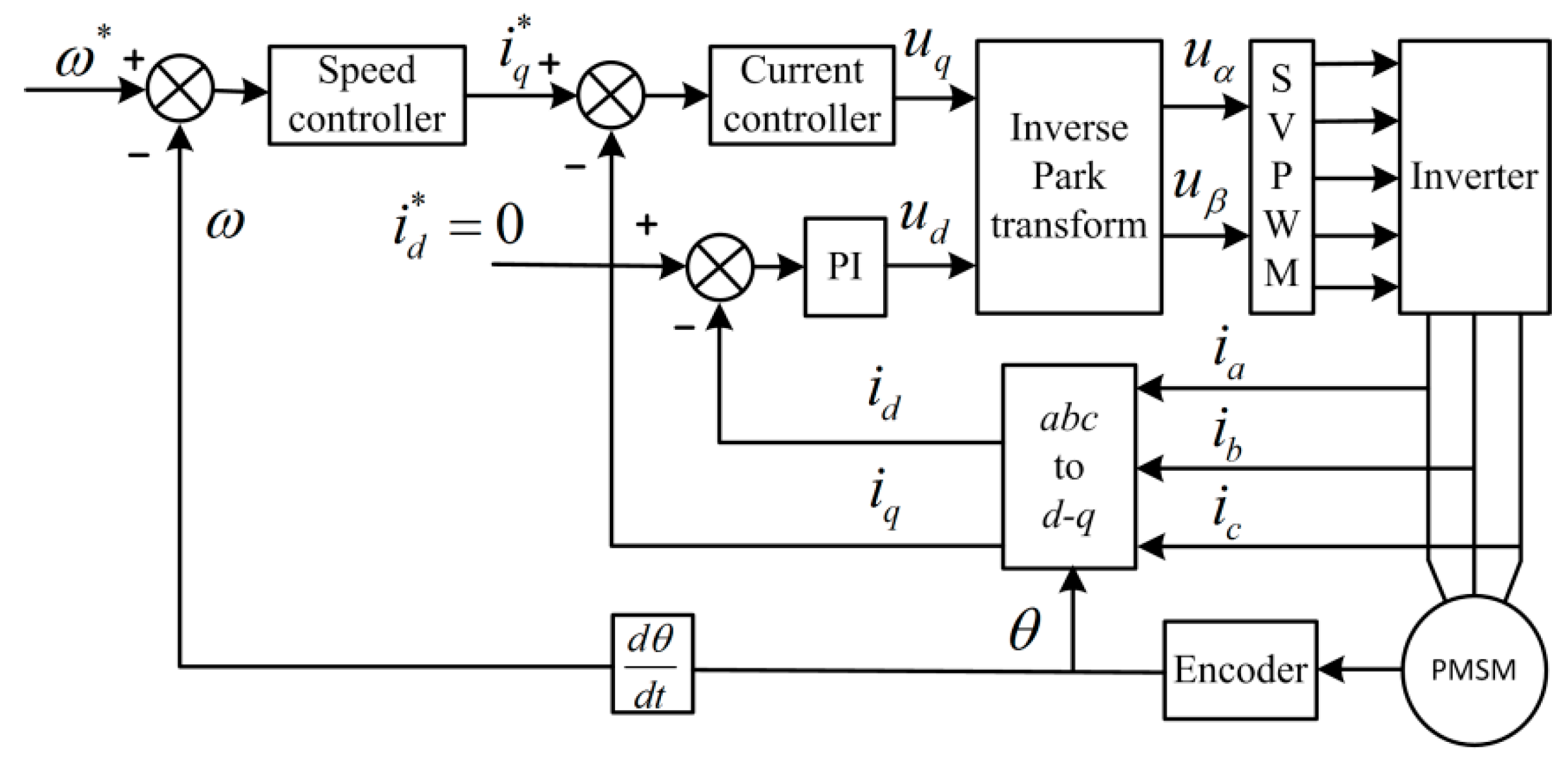
The current vector is decomposed into flux-producing component id and torque-producing component iq by coordinate transformation, therefore id and iq can be regulated separately. Here make id = 0, so that the electromagnetic torque of the motor can be controlled only by iq. Finally, the PMSM speed-regulation problem is simplified to iq regulation. The general structure of PMSM speed-regulation system is shown in Figure 1. The PMSM system includes a speed loop and two current loops. Here a PI controller is adopted in d-axis current loop. In this paper, we mainly design controller and disturbance compensator for speed loop and iq loop.
3. Controller Design
In practical industrial application, PMSM is affected by disturbance, which includes external disturbance and internal disturbance. Despite controller is robust, but these nonlinear disturbances still have an impact on system, moreover, feedback-based control method cannot react promptly to disturbances. For speed loop, a sliding mode speed regulation controller is designed, and a feed-forward compensator based on ESO is designed for not only speed loop but q-axis current loop.
3.1. Speed Loop Controller Design
The process of the system reaching the sliding surface from any initial state is called reaching motion, the sliding mode accessibility condition can only ensure that the system state can reach sliding surface, but there is no limitation on the motion trajectory. The reaching law can make the system state reach sliding surface according to the designed trajectory and improve the dynamic quality of reaching motion.
The differential equation of mechanical angular speed is shown as:
Define the state variable is defined as:
where ω* is reference speed. Because the first-order model of PMSM is adopted, so iq is approximately equal iq*. Conventionally, the response time of current loop is faster than speed loop, if control period of speed loop is more than 10 times of current loop, the approximate error can be neglected.
The state equation can be rewritten as:
where , , .
There are two main disturbances in PMSM operation: external disturbance which includes load change and reference signal change, and inertial disturbance which includes parameters change and unmolded dynamics.
As we know the disturbance of the system mainly consists of the following three parts: (1) disturbance caused by load change, (2) disturbance caused by speed change, (3) disturbance caused by reference speed change.
However, it would be difficult to observe their disturbances separately, so we define the set of all disturbances as lumped disturbance R, and the same effect can be achieved by compensating the lumped disturbance R. Indeed, we expended R as a new state variable x2; x defined as x1, and establishes a new second-order model.
where is the disturbance caused by load change, is the viscous friction disturbance caused by speed change.
The ESO is designed as:
where α1, α2 are constant gain, z1, z2 are the estimated values of speed error and lumped disturbance, respectively. The high-gain error feedback in ESO makes the observer dynamic much faster than system; ESO is equivalent to the fast-changing subsystem in the system, which can ensure the fast convergence of the error and high estimation accuracy. But the high gain observer will produce a peak when initial set value differs greatly from system actual value. For example, for a step reference signal, the initial value of error e = ω* at t = 0 s. Large error can cause a large initial impact on system to cause a peak. For peak caused by difference initial value, a transition process is designed.
where t is time, tj is transition time, β is a gain. In the initial stage t ⟶ 0, β ⟶ 0, which mitigate peak caused by different initial values, with t ⟶ tj, β; can smoothly transit to the normal gain value. The ESO can be redesigned as:
In order to design the sliding mode control law for Equation (8), here, we define an integral sliding surface as:
where c is the integral gain (c > 0). The reaching law is chosen as:
where ε, k are positive real numbers, sign() is symbolic function. Substituting the estimated lumped disturbance z2 into Equation (5) yields the derivative of s as:
and an ESO-based sliding mode controller can be designed as:
Defining a Lyapunov function is as:
To differential yields:
here we quote a conclusion in [34], if the gain of ESO (11) is large enough, then the observer error , is the derivative of lumped disturbance.
From Equation (17)
When the sliding mode motion occurs on sliding surface s = 0, we can derive
If c > 0, the existence condition of sliding mode and exponential convergence of x1 can be guaranteed.
3.2. Design of q-Axis Current Controller
As the inner loop of a cascade control structure, the disturbance of q-axis current loop cannot be ignored. Conventionally, compensating the disturbance of q-axis current loop can improve the robustness of the whole cascade structure.
The differential equation of q-axis current loop is shown as:
where p is differential operator, ωe is synchronous speed (rad/s).
From Equation (19), we can obtain:
We define the lumped disturbance of q-axis current loop as:
Here, Rq is expended as a new state variable. The state-space form is as follows:
The ESO for q-axis current loop is designed as:
Finally, the controller can be designed as:
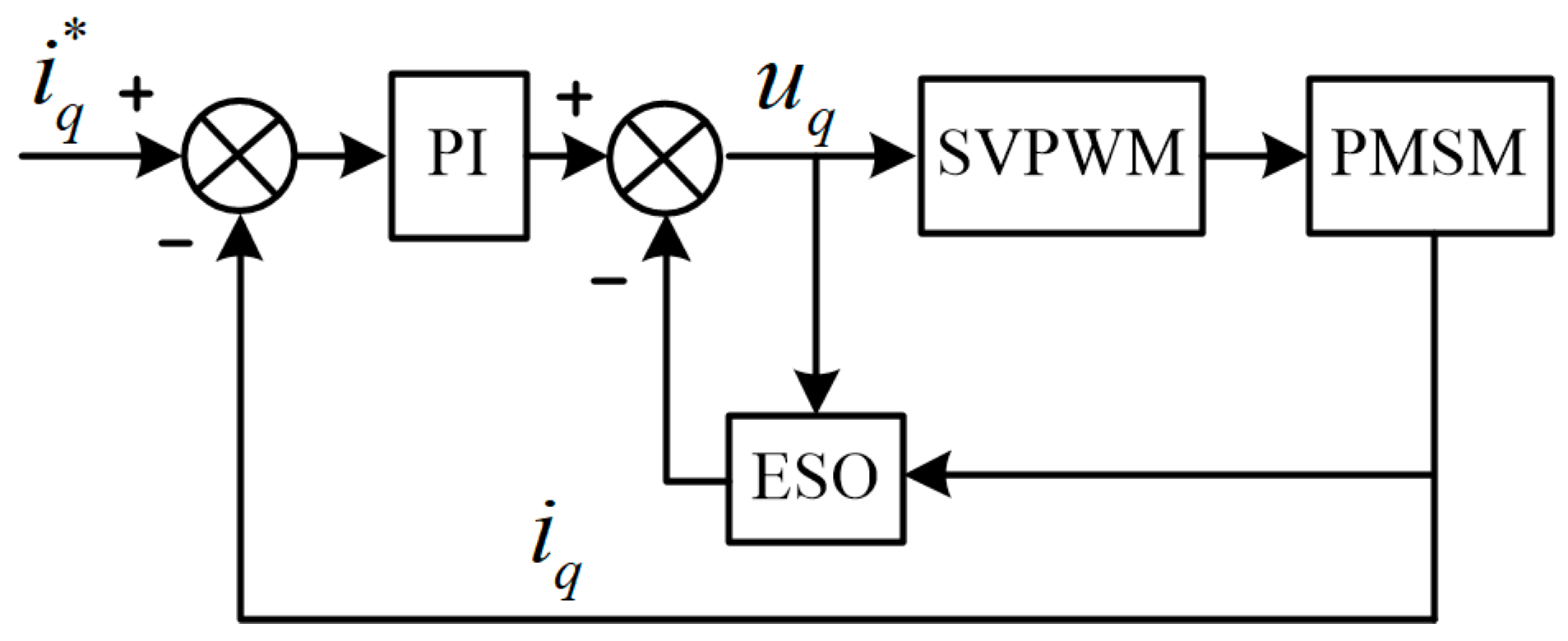
The block diagram of ESO-based q-axis current loop is shown in Figure 2.
Remark 1.
Some scholars may doubt the effectiveness of ESO because the quantitative stability analysis has not been given. In [34], the error analysis of second-order ESO under constant disturbance is given, and the conclusion is that the observation error of ESO can be made small enough by selecting appropriate parameters. But the premise is steady-state and constant disturbance, and the quantitative analysis is also difficult and challenging. Actually, ESO has been applied in many papers and practical system, and many cases show that ESO is an effective estimation method. Therefore, ESO is applied in this paper, and our simulations and experiments prove the effectiveness of ESO.
3.3. Transition Peocess Based on TD
We hope the output speed ω of system to track the step reference signal ω* as fast as possible, so a large error proportional gain is generally used. However, increasing the error proportional gain will make the closed-loop system become an under-damped and overshoot occurs, which is a contradiction between rapidity and overshoot. In fact, any system has inertia, the output speed ω can only change from zero, but the reference signal ω* is a step signal. Therefore, the initial value of error e = ω* at t = 0 s. Large error proportional gain can cause a large initial impact on the system, which make the system easy overshoot. If the initial error can be reduced, a large error proportional can be used to speed up the transition process. Therefore, a suitable transition process is arranged according to the reference signal ω*, and the output ω tracks the transition process to reach the control target. In this paper a tracking-differentiator (TD) from ADRC is used as the transition process.
where h is the integration time step, r is the speed factor that determines the tracking speed, sign() is symbolic function, H1 is the transition process of reference signal, H2 is the differential of transition process.
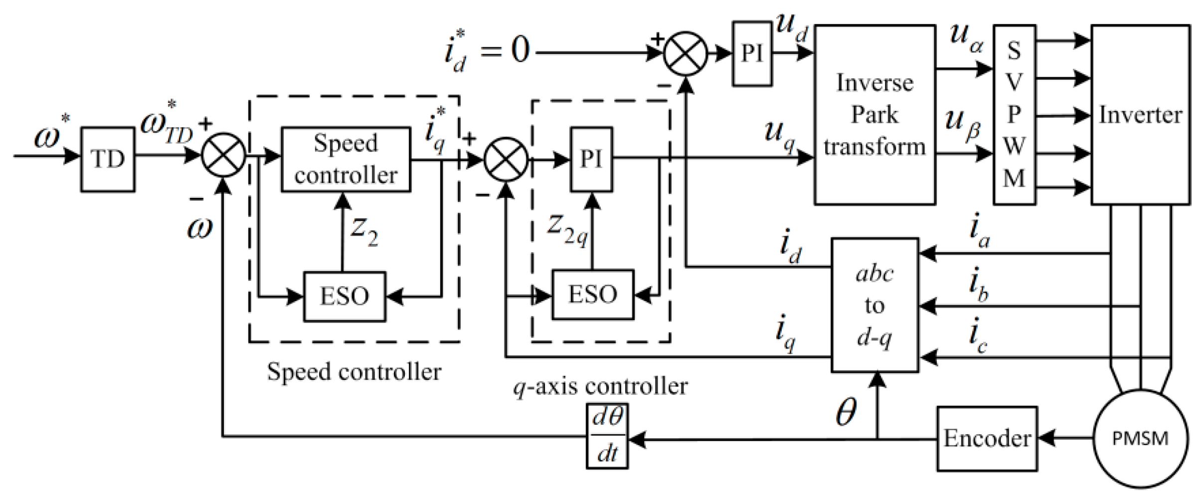
Finally, the feedforward-based PMSM speed regulation system is shown in Figure 3.
4. Simulation and Experiment Results
Simulations and experiments are done to verify the effectiveness of the proposed method. In this section, ESO-based method only for speed loop is named single-ESO method, ESO-based method for speed loop and q-axis is named double-ESO method. The parameters of PMSM are as follows: Rs is 4 Ω, Ld and Lq are 0.0006 H, J is 0.002 Kg·m2, Bm is 0.00054, np is 4.
4.1. Simulation Results
The simulations are simulated by Simulink of MATLAB 2016b. Solver is ode3, fundamental sample time is 0.00001 s, reference speed ω* = 1000 rpm, the load torque change from 0.1 N/m to 0.3 N/m at T = 1.5 s, the proportional gain and integral gain for current loop are 100 and 1000, respectively. α1 = 10,000, α2 = 50,000, α1q = 3000, α2q = 100,000, ε = 0.5.
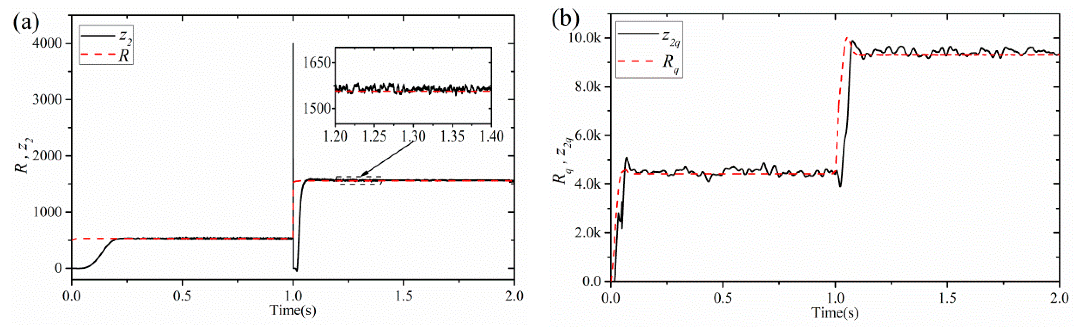
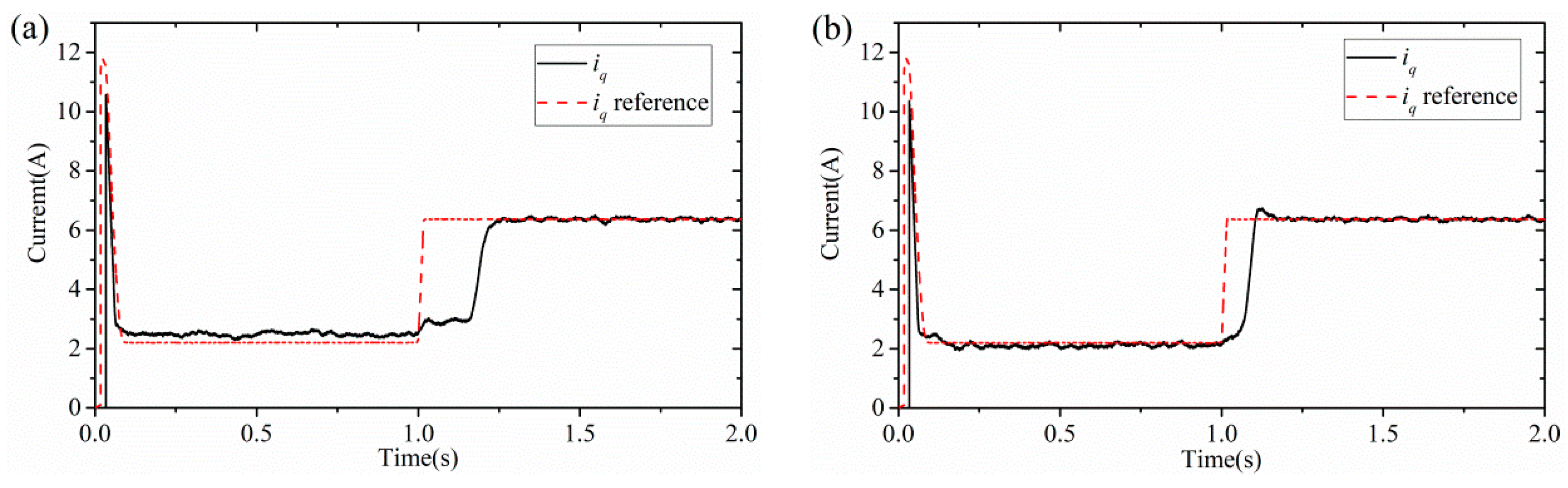
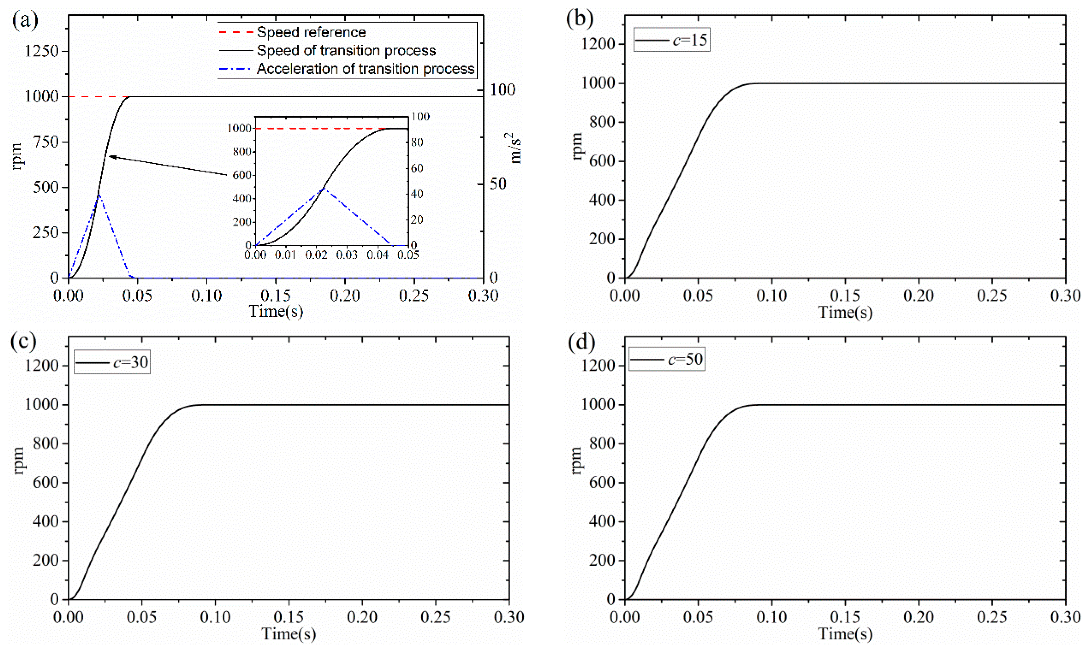
The estimated resulted of ESO for speed loop and q-axis current loop are shown in Figure 4, respectively. It can be seen from Figure 4 that the estimated value of ESO is similar to the theoretical value of the disturbance, which indicates that ESO can accurately estimate the disturbance of the system. This provides a basis for compensating the disturbances. The speed curves of single-ESO method and double-ESO method are shown in Figure 5, respectively. It can be seen that the system using double-ESO method has batter disturbance rejection ability. In Figure 6, disturbance compensation improves the dynamic response of q-axis current loop. In Figure 7, a transition process is obtained by TD, the system will track this transition signal instead of step signal. Therefore, the transition process extends the range of system parameters and improves the robustness.
4.2. Experiment Results
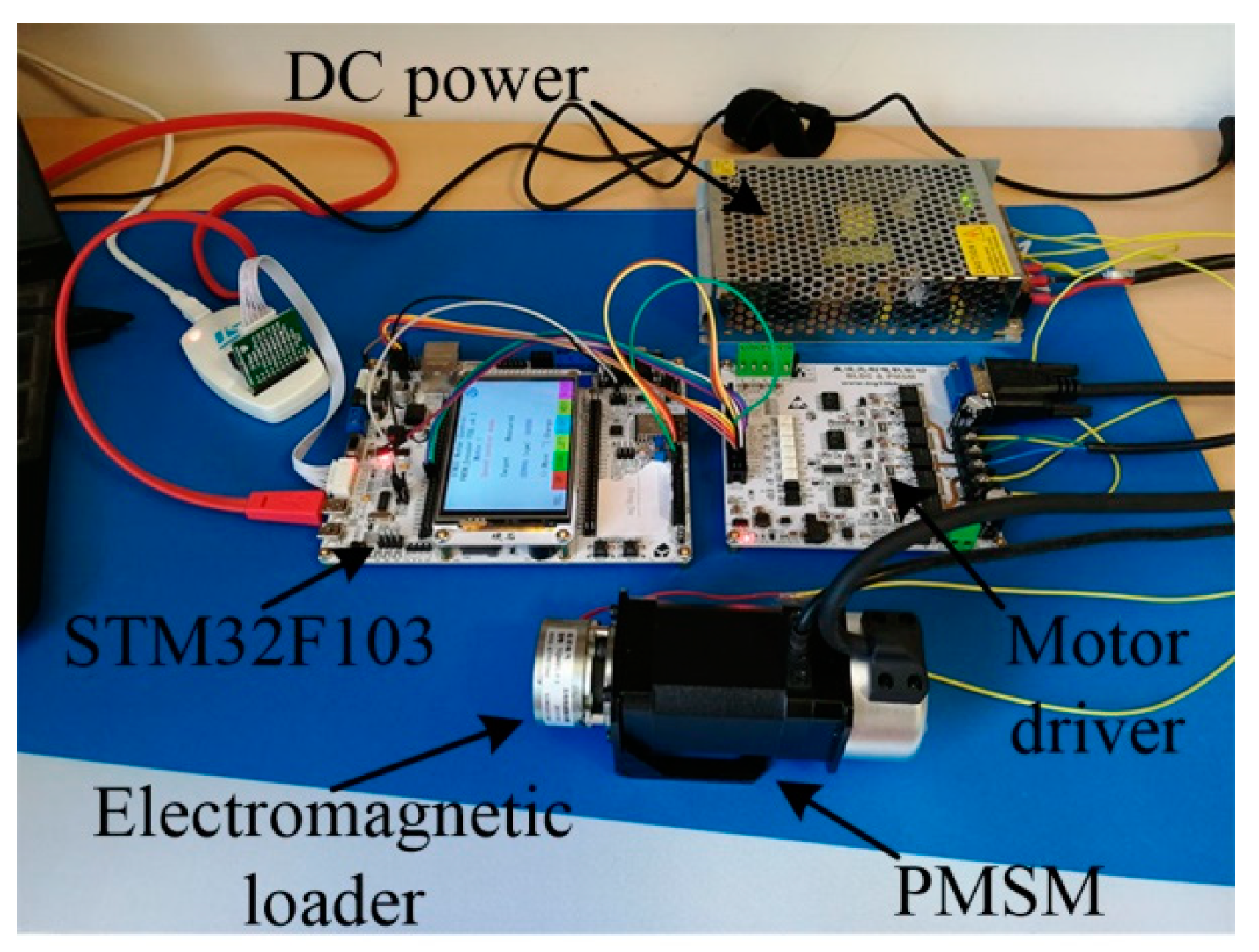
A test device is established to verify the proposed method, and is shown in Figure 8. The test deice consists of controller, motor driver, PMSM. The controller is STM32F103, FOC, and SVPWM are implemented by C-program, the clock frequency of controller is 72 MHz, the sampling time of speed loop is 10 ms, the PWM frequency is 16 KHz, current sensing by isolated current sensors (ICS), an encoder of 1000 lines is used. The max speed of motor is 3000 rpm and the rated current is 3.13 A. The serial port communicating baud rate between the STM32F103 and computer is 115,200.
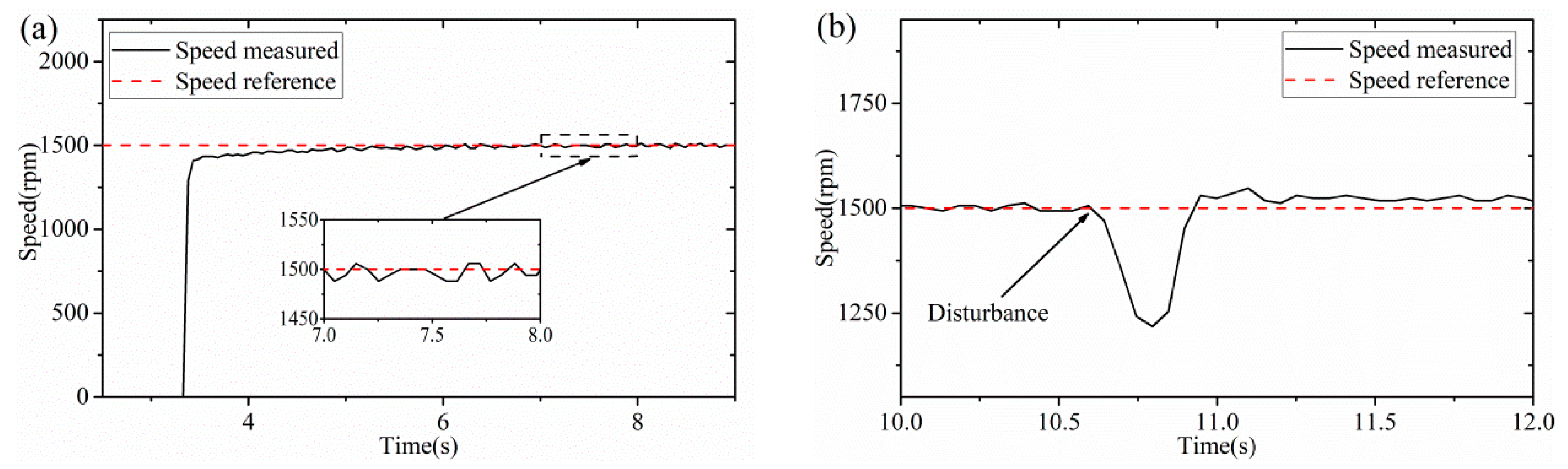
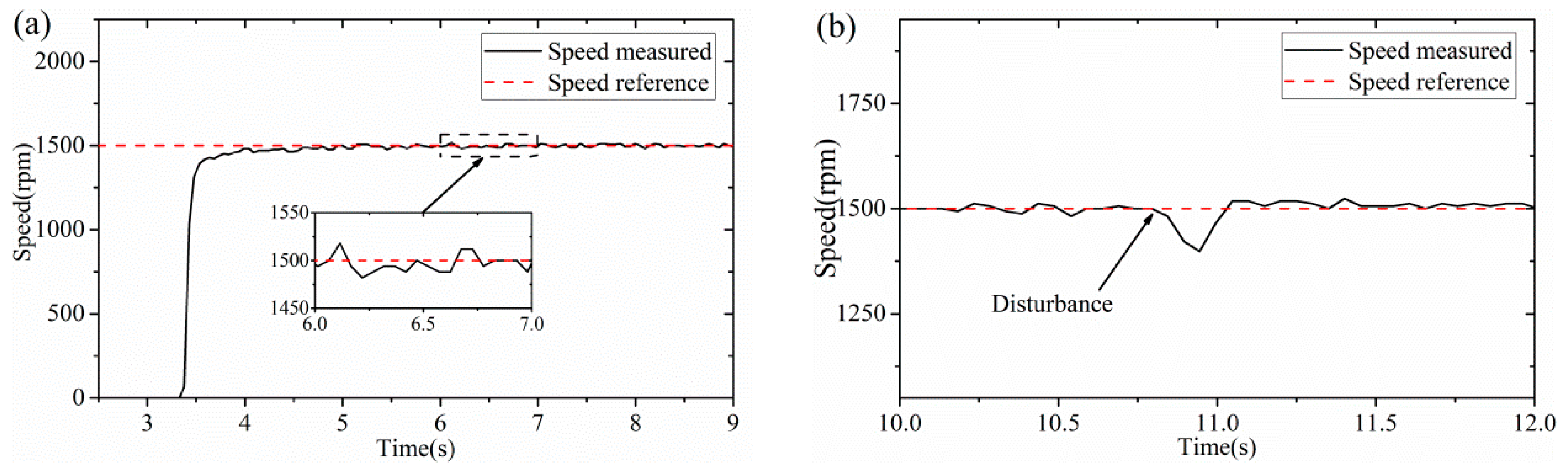
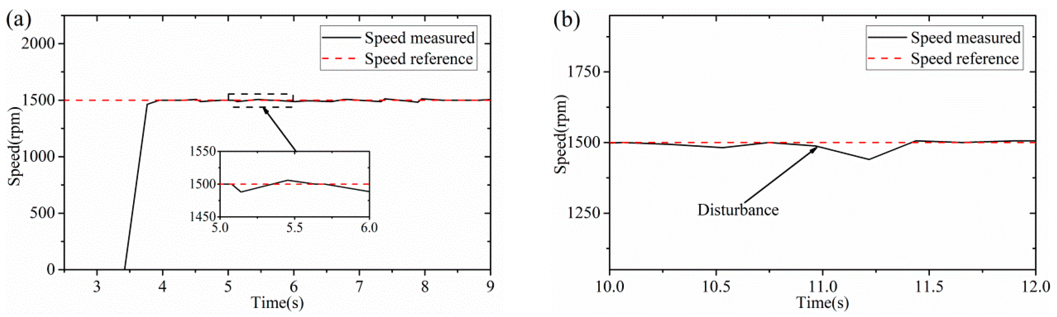
In order to verify the effectiveness of the proposed method, the proposed method is compared with other controllers. The speed curve under PI speed controller is shown in Figure 9, the proportional gain and integral gain of speed PI controller are 200 A/rad/s and 50 A/rad, respectively. The proportional gain and integral gain of current loop PI controller are 572 V/A and 121 V/A s, respectively. The parameters of sliding mode speed controller are as follows: c = 21, ε= 50, k = 0.0075. The parameters of ESO are as follows: α1 = 3000, α2 = 3000. The speed curve under speed loop sliding mode controller is shown in Figure 10, the current loop controllers are PI. The speed curve under SMC with speed loop compensation is shown in Figure 11. In Figure 12, the speed controller is sliding mode controller, and disturbance compensation based on ESO is designed for speed loop and q-axis current loop.
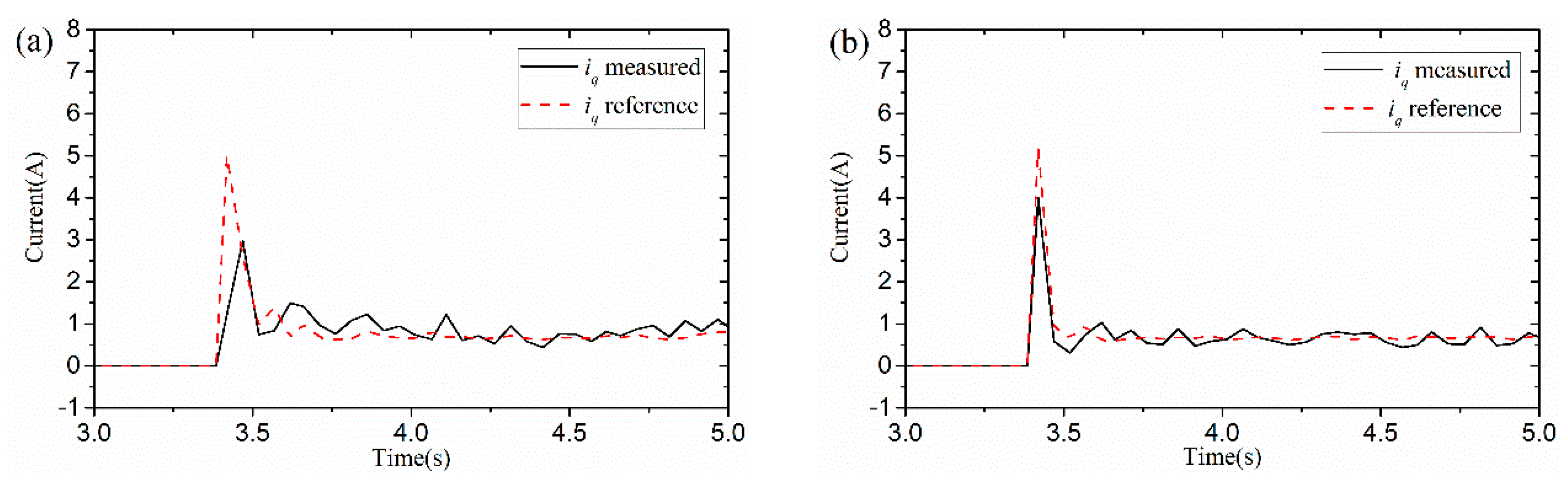
It can be seen that PI has the worst performance and cannot handle disturbance very well. In Figure 10 and Figure 11, speed sliding mode controller and speed loop disturbance compensation technology can significantly improve the anti-disturbance ability of the system. In Figure 12 and Figure 13, current loop disturbance technology can speed up the dynamic response of the system and shorten the adjustment time. Moreover, it can make iq tracking iq reference faster and more stable. A detail comparison is shown in Table 1.
5. Conclusions
In this paper, a robust control method based on feed-forward compensation has been proposed for PMSM speed-regulation system. A feed-forward based on ESO is introduced in speed loop and q-axis current loop to improve the dynamic response and robustness. By means of the disturbance estimation for feed-forward compensation, the compensator can generate a compensation signal to reduce the interference of lumped disturbance, which include external disturbance and internal disturbance, in the system. In particular, compensation for current loop disturbances significantly improves the performance and robustness of the system. A transition process of reference signal is introduced, which can reduce the initial error and increase the range of error feedback gain to improve system robustness. Both simulation and experimental results have been presented to verify the feasibility of the proposed method.
Author Contributions
Conceptualization: Y.M., methodology: Y.M. and Y.L.; formal analysis: Y.L. and Y.M.; writing—original draft preparation: Y.M.; writing—review and editing: Y.L.; supervision: Y.L. All authors have read and agreed to the published version of the manuscript.
Funding
This work was partly supported by National Natural Science Foundation of China (Grant no. U1910211).
Conflicts of Interest
The authors declare no conflict of interest.
References
- Grcar, B.; Cafuta, P.; Znidaric, M.; Gausch, F. Nonlinear control of synchronous servo drive. IEEE Trans. Control Syst. Technol. 1996, 4, 177–184. [Google Scholar] [CrossRef]
- Zhou, A.M.; Wu, Y.; Zhong, L.; Chen, Q.; Guo, J. Adaptive robust control for high-speed permanent magnet synchronous motor systems. In Proceedings of the 2017 3rd IEEE International Conference on Control Science and Systems Engineering (ICCSSE), Beijing, China, 17–19 August 2017; pp. 346–350. [Google Scholar]
- Xu, Y.P.; Hou, Y.L.; Li, Z.H. Robust predictive speed control for SPMSM drives based on extended state observers. J. Power Electron. 2019, 19, 497–508. [Google Scholar]
- Ye, J.G.; Yang, J.H.; Xie, D.S.; Huang, B.Z. Strong robust and optimal chaos control for permanent magnet linear synchronous motor. IEEE Access 2019, 7, 57907–57916. [Google Scholar] [CrossRef]
- Choi, H.H.; Jung, J.W. Takagi-sugeno fuzzy speed controller design for a permanent magnet synchronous motor. Mechatronics 2011, 21, 1317–1328. [Google Scholar] [CrossRef]
- Hou, L.M.; Li, W.H.; Shen, H.S.; Li, T.C. Fuzzy sliding mode control for systems with matched and mismatched uncertainties/disturbances based on ENDOB. IEEE Access 2019, 7, 666–673. [Google Scholar] [CrossRef]
- Khorashadizadeh, S.; Sadeghijaleh, M. Adaptive fuzzy tracking control of robot manipulators actuated by permanent magnet synchronous motors. Comput. Electr. Eng. 2018, 72, 100–111. [Google Scholar] [CrossRef]
- Liu, L.; Cartes, D.A. Synchronisation based adaptive parameter identification for permanent magnet synchronous motors. IET Control Theory Appl. 2007, 1, 1015–1022. [Google Scholar] [CrossRef]
- Luo, Y.; Chen, Y.; Ahn, H.S.; Pi, Y. Dynamic high order periodic adaptive learning compensator for cogging effect in permanent magnet synchronous motor servo system. IET Control Theory Appl. 2011, 5, 669–680. [Google Scholar] [CrossRef]
- Li, S.H.; Liu, Z.G. Adaptive speed control for permanent-magnet synchronous motors system with variations of load inertia. IEEE Trans. Ind. Electron. 2009, 5, 3050–3059. [Google Scholar]
- Barambones, O.; Garrido, A.J.; Maseda, F.J. Integral sliding-mode controller for induction motor based on field-oriented control theory. IET Control Theory Appl. 2007, 1, 786–794. [Google Scholar] [CrossRef]
- Huang, Y.; Sung, C. Implementation of sliding mode controller for linear synchronous motors based on direct thrust control theory. IET Control Theory Appl. 2010, 4, 326–338. [Google Scholar] [CrossRef]
- Wang, X.; Reitz, M.; Yaz, E.E. Field oriented sliding mode control of surface-mounted permanent magnet ac motors: Theory and applications to electrified vehicles. IEEE Trans. Veh. Technol. 2018, 67, 10343–10356. [Google Scholar] [CrossRef] [Green Version]
- Linares-Flores, J.; García-Rodríguez, C.; Sira-Ramírez, H.; Ramírez-Cárdenas, O.D. Robust backstepping tracking controller for low-speed PMSM positioning system: Design, analysis, and implementation. IEEE Trans. Ind. Inform. 2015, 11, 1130–1141. [Google Scholar] [CrossRef]
- Wu, S.F.; Zhang, J.W. A terminal sliding mode observer based robust backstepping sensorless speed control for interior permanent magnet synchronous motor. Int. J. Control Autom. Syst. 2018, 16, 2743–2753. [Google Scholar] [CrossRef]
- Ning, B.; Cheng, S.M.; Qin, Y. Direct torque control of PMSM using sliding mode backstepping control with extended state observer. J. Vib. Control 2018, 24, 694–707. [Google Scholar] [CrossRef]
- Zhao, D.Z.; Li, C.W.; Ren, J. Speed synchronization of multiple induction motors with adjacent cross-coupling control. IET Control Theory Appl. 2010, 4, 119–128. [Google Scholar] [CrossRef]
- Zhang, X.; Sun, L. Nonlinear speed control for PMSM using sliding mode control and disturbance compensation techniques. IEEE Trans. Power Electron. 2013, 28, 1358–1368. [Google Scholar] [CrossRef]
- Ohnishi, K. A new servo method in mechatronics. Trans. Jpn. Soc. Electr. Eng. 1987, 107, 83–86. [Google Scholar]
- Wei, X.; Guo, Z.; Liu, X. Composite hierarchical anti-disturbance control for nonlinear robotic systems with robust nonlinear disturbance observer. In Proceedings of the 32nd Chinese Control Conference, Xi’an, China, 26–28 July 2013; pp. 2694–2699. [Google Scholar]
- He, X.; Kou, G.; Calaf, M. In-ground-effect modeling and nonlinear-disturbance observer for multirotor unmammed aerial vehicle control. J. Dyn. Syst. Meas. Control-Trans. ASME 2019, 141, 071013. [Google Scholar] [CrossRef] [Green Version]
- Zhao, W.X.; Jiao, S.; Chen, Q.; Xu, D.Z. Senseless control of a linear permanent-magnet motor based on an improved disturbance observer. IEEE Trans. Ind. Electron. 2018, 65, 9291–9300. [Google Scholar] [CrossRef]
- Li, S.; Zhou, M.; Yu, X. Design and implementation of terminal sliding mode control method for PMSM speed regulation system. IEEE Trans. Ind. Inform. 2013, 7, 1879–1891. [Google Scholar] [CrossRef]
- Yan, J.; Wang, H.; Huang, S. Load disturbance observer-based complementary sliding mode control for PMSM of the mine traction electric locomotive. Int. J. Fuzzy Syst. 2019, 21, 1051–1058. [Google Scholar] [CrossRef]
- Yan, Y.D.; Yang, J.; Sun, Z.X.; Zhang, C.L.; Li, S.H. Robust speed regulation for PMSM servo system with multiple sources of disturbances via an augmented disturbance observer. IEEE-ASME Trans. Mechatron. 2018, 23, 769–780. [Google Scholar] [CrossRef]
- Han, J.Q. The extended state observer of a class of uncertain systems. Control Decis 1995, 10, 85–88. (In Chinese) [Google Scholar]
- Han, J.Q. From PID to active disturbance rejection control. IEEE Trans. Ind. Electron. 2009, 56, 900–906. [Google Scholar] [CrossRef]
- Li, S.; Zong, K.; Liu, H. A composite speed controller based on a second-order model of PMSM system. Trans. Inst. Meas. Control 2011, 33, 522–541. [Google Scholar]
- Du, B.; Wu, S.; Han, S.; Cui, S. Application of linear active disturbance rejection controller for senseless control of internal permanent-magnet synchronous motor. IEEE Trans. Ind. Electron. 2016, 63, 3019–3027. [Google Scholar] [CrossRef]
- Wang, G.L.; Wang, B.W.; Li, C.; Xu, D.G. Weight-transducerless control strategy based on active disturbance rejection theory for gearless elevator drives. IET Electr. Power Appl. 2016, 11, 289–299. [Google Scholar] [CrossRef]
- Li, S.; Xia, C.; Zhou, X. Disturbance rejection control method for permanent magnet synchronous motor speed-regulation system. Mechatronics 2012, 22, 706–714. [Google Scholar] [CrossRef]
- Zwerger, T.; Mercorelli, P. Combining an internal SMC with an external MTPA control loop for an interior PMSM. In Proceedings of the 2018 23rd International Conference on Methods and Models in Automation and Robotics, Miedzyzdroje, Poland, 27–30 August 2018; art no. 8485900. pp. 674–679. [Google Scholar]
- Zwerger, T.; Mercorelli, P. Combining SMC and MTPA using an EKF to estimate parameters and states of an interior PMSM. In Proceedings of the 2019 20th International Carpathian Control Conference (ICCC), Krakow-Wieliczka, Poland, 26–29 May 2019; pp. 1–6. [Google Scholar]
- Han, J.Q. Error analysis of the second order ESO. J. Syst. Sci. Math. Sci. 1999, 19, 465–471. (In Chinese) [Google Scholar]
Figure 1.
The block diagram of permanent magnet synchronous motor (PMSM) speed-regulation system.

Figure 2.
The block diagram of q-axis current controller based on extended state observer (ESO).

Figure 3.
Diagram of feedforward-based PMSM system.

Figure 4.
Comparison of the actual disturbance with ESO estimates: (a) actual disturbance R, estimated disturbance z2 of speed loop, (b) actual disturbance Rq, estimated disturbance z2q of q-axis loop.
Figure 4.
Comparison of the actual disturbance with ESO estimates: (a) actual disturbance R, estimated disturbance z2 of speed loop, (b) actual disturbance Rq, estimated disturbance z2q of q-axis loop.

Figure 5.
Speed curves under signal-ESO and double-ESO: (a) response of speed under signal-ESO, (b) response of speed under double-ESO.
Figure 5.
Speed curves under signal-ESO and double-ESO: (a) response of speed under signal-ESO, (b) response of speed under double-ESO.

Figure 6.
iq and iq reference with current loop compensation and without current loop compensation: (a) curve of iq and iq reference without q-axis current compensation, (b) curve of iq and iq reference with q-axis current compensation.
Figure 6.
iq and iq reference with current loop compensation and without current loop compensation: (a) curve of iq and iq reference without q-axis current compensation, (b) curve of iq and iq reference with q-axis current compensation.

Figure 7.
Curves of transition process and speed curves using transition process: (a) speed curve and acceleration curve of transition process, (b) speed curve under c = 15, (c) speed under c = 30, (d) speed under c = 50.
Figure 7.
Curves of transition process and speed curves using transition process: (a) speed curve and acceleration curve of transition process, (b) speed curve under c = 15, (c) speed under c = 30, (d) speed under c = 50.

Figure 8.
Experimental test device.

Figure 9.
Speed curve under PI controller: (a) the speed curve, (b) speed curve when load disturbance.
Figure 9.
Speed curve under PI controller: (a) the speed curve, (b) speed curve when load disturbance.

Figure 10.
Speed curve under sliding mode control (SMC): (a) the speed curve, (b) speed curve when load disturbance.
Figure 10.
Speed curve under sliding mode control (SMC): (a) the speed curve, (b) speed curve when load disturbance.

Figure 11.
Speed curve under SMC with speed loop compensation: (a) the speed curve, (b) speed curve when load disturbance.
Figure 11.
Speed curve under SMC with speed loop compensation: (a) the speed curve, (b) speed curve when load disturbance.

Figure 12.
Speed curve under SMC with speed loop compensation and current loop compensation: (a) the speed curve, (b) speed curve when load disturbance.
Figure 12.
Speed curve under SMC with speed loop compensation and current loop compensation: (a) the speed curve, (b) speed curve when load disturbance.

Figure 13.
iq and iq reference with current loop compensation and without current loop compensation: (a) curve of iq and iq reference without q-axis current compensation, (b) curve of iq and iq reference with q-axis current compensation.
Figure 13.
iq and iq reference with current loop compensation and without current loop compensation: (a) curve of iq and iq reference without q-axis current compensation, (b) curve of iq and iq reference with q-axis current compensation.


Table 1.
Comparisons between control methods.
| Control Method | Overshoot | Setting Time | Speed During Disturbance | Steady-State Error | |
|---|---|---|---|---|---|
| Decrease | Increase | ||||
| Speed: PI Current: PI | 26% | 0.3s | −240 rpm | 336 rpm | ±18 rpm |
| Speed: SMC Current: PI | 0% | 1.27s | −246 rpm | 48 rpm | ±12 rpm |
| Speed: SMC + ESO Current: PI | 0% | 1.06s | −112 rpm | 18 rpm | ±12 rpm |
| Speed: SMC + ESO Current: PI + ESO | 0% | 0.531s | −28 rpm | 18 rpm | ±10 rpm |
© 2020 by the authors. Licensee MDPI, Basel, Switzerland. This article is an open access article distributed under the terms and conditions of the Creative Commons Attribution (CC BY) license (http://creativecommons.org/licenses/by/4.0/).
Share and Cite
MDPI and ACS Style
Ma, Y.; Li, Y. Active Disturbance Compensation Based Robust Control for Speed Regulation System of Permanent Magnet Synchronous Motor. Appl. Sci. 2020, 10, 709. https://doi.org/10.3390/app10020709
AMA Style
Ma Y, Li Y. Active Disturbance Compensation Based Robust Control for Speed Regulation System of Permanent Magnet Synchronous Motor. Applied Sciences. 2020; 10(2):709. https://doi.org/10.3390/app10020709
Chicago/Turabian StyleMa, Yuxiang, and Yunhua Li. 2020. "Active Disturbance Compensation Based Robust Control for Speed Regulation System of Permanent Magnet Synchronous Motor" Applied Sciences 10, no. 2: 709. https://doi.org/10.3390/app10020709
Note that from the first issue of 2016, this journal uses article numbers instead of page numbers. See further details here.