Article

The Logic-Based Supervisor Control for Sun-Tracking System of 1 MW HCPV Demo Plant: Study Case

High Concentration Photovoltaic R & D Project, Institute of Nuclear Energy Research, Taoyuan 32546, Taiwan
*
Author to whom correspondence should be addressed.
Appl. Sci. 2012, 2(1), 100-113; https://doi.org/10.3390/app2010100
Submission received: 4 January 2012 / Revised: 30 January 2012 / Accepted: 2 February 2012 / Published: 7 February 2012

Abstract

:
This paper presents a logic-based supervisor controller designed for trackers for a 1MW HCPV demo plant in Taiwan. A sun position sensor on the tracker is used to detect the sun position, as the sensor is sensitive to the intensity of sun light. The signal output of the sensor is partially affected by the cloud, which has a hard control position with the traditional PID control. Therefore we have used logic-based supervisor (LBS) control which permits switching the PID control to sun trajectory under sunny or cloudy conditions. To verify the stability of the proposed control, an experiment was performed and the results show that the proposed control can efficiently achieve stabilization of the trackers of the 1MW HCPV demo plant.

1. Introduction

Recently, the problems of shortage of fossil fuel sources and global warming effects have become more and more severe. People have begun to seek various possible solutions to those problems. One of the potential options is the use of sun energy, which not only provides an alternative energy source but also improves environmental pollution. Therefore, high concentration photovoltaics (HCPV) have attracted much attention in recent years, because of their high efficiency. HCPV systems require a solar tracker to generate power compared to conventional non-concentration photovoltaic systems. The solar tracker is the key component in the HCPV system to enable accurate and stable tracking.
The Institute of Nuclear Energy Research (INER) has developed a HCPV high power generation system with III-V solar cells, as an alternative source to the application of solar photovoltaics (PV) and as a dependable energy source for mankind [1,2]. And also one MW HCPV demonstration power plant [3] (Figure 1), which covers an installation area of 2 hectares, installed at Lujhu in December 2009, generating over 1 million kWh per year, and reducing carbon dioxide emissions by approximately 660 tons annually. It is a milestone for Taiwan's government to have put the policy of energy saving and carbon reduction into practice.
In the literature, common sun tracking systems consist of open-loop and closed-loop types [4]. The sun ephemeris provides the apparent position of the sun in the sky at a given moment in time, at a given point on the earth. Facilitating formula, position counters and control methods according to the sun ephemeris, enable the solar tracker to aim at the sun. This is called open-loop control [5]. The other method of sun tracking is by using the sun position sensor to detect and maneuver the solar tracker. However, both open loop and close loop methods have their individual problems of high tracking error, such as the installation error, and influence of clouds on the sun position sensor. In [6], a lookup table was pre-established to obtain the position of the sun at any time and then the direction of tracking mechanism is adjusted to point to the direction of the sun. In [7] a type of on–off control was utilized for two-axis sun tracking. On the other hand, common closed-loop control methodologies include robust proportional (P) control, proportional-integral (PI) control, derivative (D)-like control, proportional-integral-derivative (PID) control [8,9,10,11], fuzzy control [12,13,14,15], Linear-Quadratic Regulator(LQG) control [16] or H-infinity(H∞) control [17,18]. Various controllers have individual advantages and disadvantages [17]. For instance, PID control and fuzzy control could be good options when an accurate model of the tracking system is absent, while LQG or H∞ control are preferred if higher accuracy tracking performance or tracking robustness against exogenous disturbance, such as wind gusts or cloud effects, is the main concern [19,20,21].
Therefore, a hybrid method combining both algorithms is now proposed [22,23,24,25]. Up to date, the research of hybrid strategy for keeping the solar tracker in a precise position has needed a large amount of random access memory (RAM) to store parameters such as tracker position data or to use frequent search functions to search for the sun position precisely, even though those functions violate low cost principles and reduce the motor life-span respectively.
An alternative idea of employing logic-based supervisor (LBS) control has had a great impact on sun tracking systems. Control using logic-based switching [26,27] has been proposed and employed, Switching between controllers is a subject of special interest: the process to be controlled might change the mode of operation so as to render no single controller capable of guaranteeing closed-loop stability. Switching between controllers might be crucial in protecting the process against wind-up effects. Changes in the dynamics of the process under control and/or in the character of the disturbances might require prompt changes in the control action in order to maintain satisfactory closed-loop performance.
The stability of the sun tracking system is one of the main concerns for power generated efficiency of a one MW HCPV demonstration power plant. We have employed a switching supervisory control to solve the instability problem for sun tracking systems.
This paper is organized as follows. In Section 2, a general description of the architecture and the principle of a sun tracking system is presented. In Section 3, the control strategies of the LBS control are discussed and conducted in addition to a control theory offered for the switching control design concept. In Section 4, the experiment results are discussed and a comparison made of the proposed controls. Finally, some conclusions are offered in Section 5.

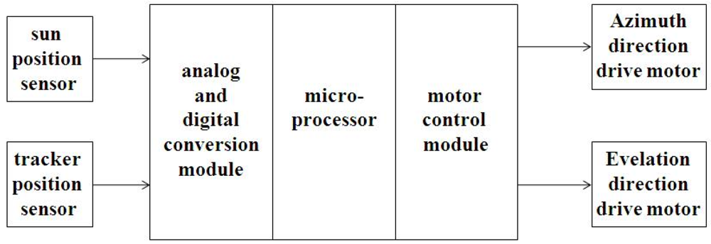
2. Analysis and Design of a Sun Tracking Control System

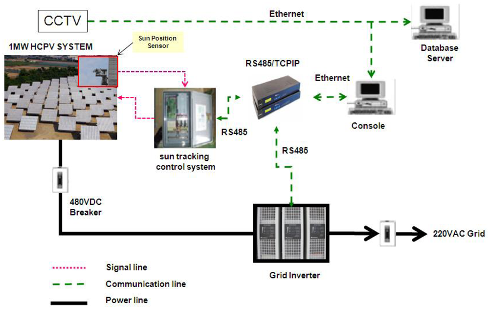
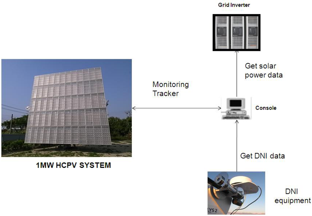
2.1. Power Plant Tracking and Monitoring System

A MW HCPV demonstration power plant system (Figure 1) consists of a monitoring and power generation unit. The monitoring unit includes a Closed-Circuit Television (CCTV), electrical characteristics of the driver and the receiver standard (RS485), RS485/Transmission Control Protocol Internet Protocol (IPTCP/IP) converter, console, and database server. The power generation unit includes HCPV modules, a tracker, a sun tracking control system, a grid inverter. A CCTV system was implemented for remote monitoring of the HCPV demonstration power plant system. The DC power output of the HCPV modules was connected to the inverter, which tracks the maximum peak power point to keep the HCPV modules output power in the optimum condition. There are two kinds of power measurement design implementation in the system. One is the measurement of DC current and voltage for the HCPV modules output power, and the other is the measurement of AC current and voltage for the consumption power of the load. The console collects those signals from power measurement devices through the RS485 communication, RS485/TCP/IP converter and Ethernet network, and stores the data on the database server.
Figure 1. One MW High concentration photovoltaics (HCPV) demonstration power plant system architecture.
Applsci 02 00100 g001
This tracker is equipped with a sun position sensor and an azimuth-elevation tracker, consisting of two axes. One axis is a vertical pivot shaft that allows the device to be swung to a compass point. The other axis is a horizontal elevation pivot mounted upon the azimuth platform. The sun position sensor oriented to the sun direction is composed mainly of four photo detectors, located 90 degrees apart from each other and oriented to the cardinal points.
The sun tracking control system, in Figure 2, includes the sun position sensor and the mechanism declined angle adjuster, the tracker position encoder, the analog and digital conversion module, the motor control module, the micro-processor, the azimuth and the elevation motor. The sun position sensor is mounted horizontally on the mechanism declined angle adjuster. The mechanism declined angle adjuster has four springs to adjust the declined angle in the west/east and south/north direction. It enables the sun position sensor mechanism to keep the same horizontal angle as the solar modules. The tracker position encoder uses the reed switch to detect the stroke length of the actuator in elevation and the displacement of motor in azimuth to calculate the solar tracker position. The elevation and azimuth angle of the solar tracker are stored as pulses count per minute. The analog and digital conversion module is for converting the signal of the sun position sensor to a digital signal. The motor control module receives the micro-processor command to start or stop the azimuth and elevation motor.
Figure 2. Sun tracking control system.
Applsci 02 00100 g002
Figure 3. Sun position sensor.
Applsci 02 00100 g003
There are four photo detectors located in the sun position sensor (Figure 3), at 90 degrees apart from each other, and oriented to the four cardinal points. Two differential signals between east (E) and west (W) detectors, and south(S) and north (N) detectors are sent to the tracking controller. However, the sun position sensor is a simple iteration of the following equation:
Applsci 02 00100 i001
Applsci 02 00100 i002
where α represents the difference of the sun position sensor in the west-east direction, and β represents the difference of the sun position sensor in the north-south direction axis. The E, W, S, N, are the voltages measured in each direction of the detectors. The intensities of E, W, S, and N are different, if the center of the light is not at the center of the sun position sensor.

2.2. Problem Formulation

The stability problem of the sun tracking system is because the sun position sensor is influenced by the presence of clouds. A method to suppress the influence of the sensor includes the signal filter, LQG control and H∞ control. However, in this case, the sun position sensor will be fully shaded from the clouds. Hence, under a sightless condition, it is too hard to apply the controller to the above method to solve the stability problem.
In the sightless condition, we can stop the tracker tracking or still track according to the expected sun trajectory which stores the equivalent position encoder counts in the memory. In the field, if we stop the trackers, most of the trackers will not be capable of aligning to each other because the sensitivity of the sun position sensor is different and the area of light shaded by cloud is not the same.
In this case, we apply the concept of LBS control to the sun tracking control system (Figure 4). The concept of LBS control includes controller 1 for tracking and controller 2 for stabilizing trackers. The switch(S) is the output of LBS control for switching between controllers and might be crucial in cloudy conditions. Suppose that the considered sensor of the azimuth/elevation tracking system (controller 1) is modeled as P1
Applsci 02 00100 i003
where xRn is the state, u1R is the control input (the voltage to the DC motor), and y1∈ R is the measured output (the tracking error); A1, B1, and C1 are constant matrices of appropriate dimensions. The design goal is to find a static output feedback controller
Applsci 02 00100 i004
for the azimuth/elevation tracking system to achieve the minimum error y1.
The other, sun trajectory elevation tracking system (controller 2) is modeled as P2
Applsci 02 00100 i005
Applsci 02 00100 i006
where xRn is the state, u2R is the control input, and y2R is the measured output (the tracking error); A2, B2, and C2 are constant matrices of appropriate dimensions. The design goal is to find a static output feedback controller for the azimuth/elevation tracking system to achieve the minimum error y2.
The signal S: [0, ∞) → S—called the switching signal—effectively determines which controller is in the loop at each instant of time. The points of discontinuity of S correspond to a change in the candidate controller.
Figure 4. Concept of sun tracking control system.
Applsci 02 00100 g004

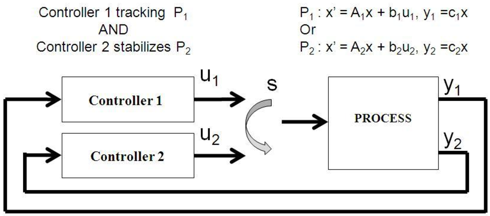
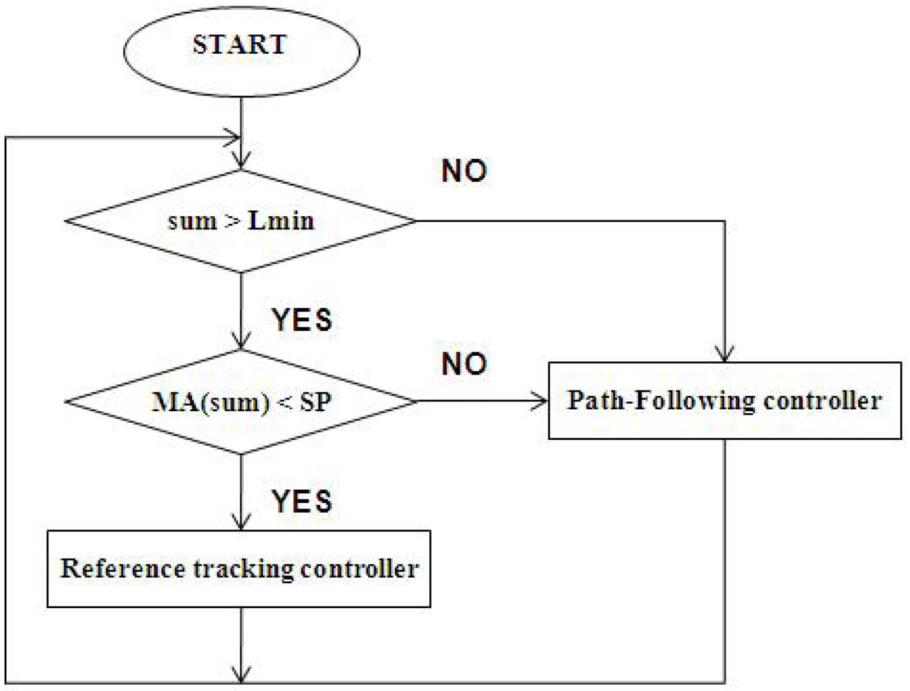
2.3. LBS Control Design

We apply the LBS control to the sun tracking control system. The control system (Figure 5) includes a LBS, reference tracking controller and a path follow tracking controller.
The reference tracking controller for azimuth and elevation is based on the value (u1) which is the output of EW or SN, and is also a kind of proportional–integral controller, a case of a PID controller where D = 0. The controller attempts to minimize the error by adjusting the tracking control inputs. PI controllers are fairly common, since derivative action is sensitive to measurement noise, however the absence of an integral term may prevent the system from reaching its target value due to the control action. Generally, stability of response is required and the process must not oscillate for any combination of tracking conditions and setpoints, though sometimes marginal stability (bounded oscillation) is acceptable or desired. Two basic requirements are regulation (disturbance rejection—staying at a given setpoint) and command tracking (implementing setpoint changes)—they refer to how well the controlled variable tracks the desired value. We apply Equations (3) and (4) to find a static output feedback controller for the azimuth/elevation tracking system to achieve the minimum error y1.
The path follow tracking controller depends on the value (u2) of the output of the sun trajectory, converting counts of the encoder to maneuver the tracker. The tracker position encoder uses the reed switch to detect the stroke length of the actuator in elevation and displacement of the motor in the azimuth to calculate the solar tracker position. The elevation and azimuth angle of the solar tracker are stored in pulse counts per hour. The analog and digital conversion module is for converting the signal of the sun position sensor to a digital signal. The motor control module receives the microprocessor command to start or stop the azimuth and elevation motor. We apply Equations (5) and (6) to find an open loop controller for the azimuth/elevation tracking system to achieve the minimum error y2.
Figure 5. Logic-based Supervisor(LBS) control in a sun tracking system.
Applsci 02 00100 g005
The LBS determines the controllers to be applied to track the sun. The supervisor inputs the u1, u2, y1 and y2 to calculate the switch Ѕ value. When Ѕ = 0, the supervisor applies controller 2. Conversely when, Ѕ = 1, the supervisor applies controller 1. It is stated as follow
Applsci 02 00100 i007
Applsci 02 00100 i008
The SUM is the sum of the sun position sensor which is E, W, S, and N. The wma_SUM is the 5 elements triangle weighted moving average. If the value of the sum is large than its setpoint, S equals 0. The controller will change to the path following tracking controller. If the value of the sum is less than its setpoint, then S equals 1. The controller will change to the reference tracking controller.
Figure 6 shows the LBS controller programming flow. After the START state, the LBS computes the sum of the sensor, if the sum is larger than the minimum of sun light (Lmin) and sum of triangle weighted moving average (wma_SUM) is smaller than the setpoint of fluctuation (SP), then the tracking system uses the reference-tracking controller. Otherwise, the tracking system uses the path follow tracking controller.
Figure 6. Flow diagram of Logic-based Supervisor(L BS).
Applsci 02 00100 g006
The reference tracking control (Figure 7) applies the proportional-integral (PI) control. The PI control algorithm computes the difference of the sun position sensor value (u1) and makes the decision that the tracker should move to face the sun until the position of u1 is minimum. Q is the deadband of the difference of the sun position sensor value.
The path following controller (Figure 8) computes the encoder value (u2) and converts to the azimuth/elevation degree of the sun. The path following control algorithm makes the decision that the tracker should move to face the sun until the position of u2 is minimum. P is the deadband of encoder value.
For a sun tracking system design, using our proposed LBS control for stability makes it easier than for the traditional control design and implement system.
Figure 7. Flow diagram of reference tracking controller.
Applsci 02 00100 g007
Figure 8. Flow diagram of path following controller.
Applsci 02 00100 g008

2.4. Experimental Setup

In the work presented in this paper, the block diagram of the experiment setup is shown in Figure 9. In the one MW HCPV demonstration power plant, the console gets the Direct Normal Irradiance (DNI) values from the DNI equipment and DC power from the grid inverter.
The console gets the sun position sensor data through the sun tracking control system and records the data and analysis.
Figure 9. Block diagram of experiment setup.
Applsci 02 00100 g009

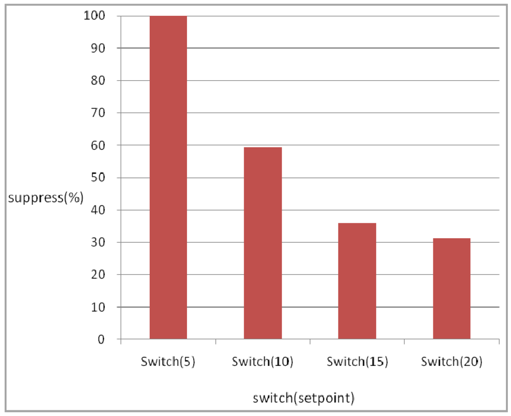
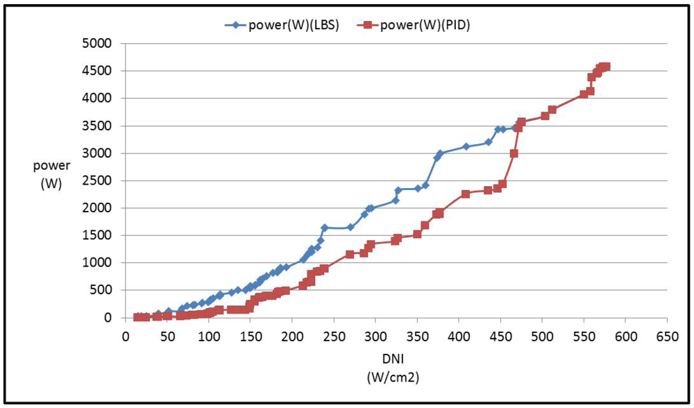
3. Results and Discussion

We obtain the data of the sun position sensor from the console, and follow Equations (1) and (2) to calculate α and β. The cloud influences the sun light, and also changes the α and β values without the sun moving. In Figure 10, the suppression rate shows the setpoint of switch(S) on 5, 10, 15, 20. The setpoint of the switch is effective in changing to the path following while the sun light changes. However, the lower the setpoint the higher the suppression rate which makes the system more stable. Conversely, the higher the setpoint the lower the suppression rate which makes the system more unstable under cloudy conditions.
Figure 10. Comparison of switch signal.
Applsci 02 00100 g010
Figure 11. Comparison of LBS control and PID control.
Applsci 02 00100 g011
Figure 11 shows the comparison between LBS control and PID control for the point where best suppression was achieved. The time traces show that between 36–66 minute, the cloud influences the sun light making the x(AZ) or y(EL) present a larger tracking error. Besides, the system is in an unstable state. The LBS control shows that between 36–66 minute, the tracking error is confined to within 30. The system is stable and bounded.
Although the lower setpoint of the switch makes the tracking system more stable, it is also inaccurate. However, the tracking system is stable and accurate, when the optimal lower setpoint of switch(S) is in the range of 10.
Figure 12 shows the comparison between LBS control (diamond point) and PID control (square point) for the output power based on the same Direct Normal Irradiance (DNI). The X axis (DNI) traces show that at 0–650 watts per cm2, the cloud influences the sun light causing different DNI. The PID control shows that at 0–470 watts per cm2, the output power is lower than LBS. The LBS control switches the reference tracking control to the path following control to get more power under low DNI. But in the range, 470–650 watts per cm2, less cloud results in less power loss in the PID control. The output power of the PID control is almost the same as the LBS control.
Figure 12. Comparison of power output between LBS control and PID control
Applsci 02 00100 g012

4. Conclusions

The proposed control scheme has been validated on a hardware prototype experimental setup of the system and for the experimental environment as show in Figure 9.
In the sun tracking system, the LBS controller enables system stability and high efficiency power production. Under sunshine conditions, the reference-tracking controller provides tracking accuracy to help HCPV power production as needed. Under cloudy conditions, the path follow tracking controller moves to follow the sun trajectory, which is stored in the memory. The sun trajectory table is sought and calculated by interpolation when required any time with location between two points. In practice, some error is introduced by calculation and by interpolation. However, the path follow tracking controller is to enable stable tracking. The other way, a reference-tracking controller is used. PID control with a sun position sensor, results in a high accuracy tracking to ±0.2 degree. However, the transition time is between the path follow tracking controller transfers to reference tracking controller or reference tracking controller transfers to path follow tracking controller. The transition time is a key element of LBS for the control system. In the sun tracker system, the transition time has no significant influence on the system performance. Because the system response time of the sun tracker is almost 15 sec with the requirement of accuracy tracking ±0.2 degree.
This paper discusses the control method of stability for the HCPV system, a LBS controller for trackers of 1 MW HCPV demo plant application. Comparing the experimental results has shown that the control method not only stabilizes trackers of the HCPV system, but also can significantly improve power production of the HCPV system due to sun light changes. The LBS control is a switching control because of its reference tracking and path follow tracking controller and is suitable to control HCPV systems.

Acknowledgments

The authors would like to thank the colleagues on the Tracking & Power team of INER HCPV project.

References and Notes

  1. Wai, R.J.; Wang, W.H.; Lin, C.Y. High-performance stand-alone photovoltaic generation system. IEEE Trans. Ind. Electron. 2008, 55, 240–250. [Google Scholar] [CrossRef]
  2. Khalil, A.A.; El-Singaby, M. Position control of sun tracking system. In Proceedings of the 46th IEEE International Midwest Symposium on Circuits and Systems, Cairo, Egypt, 27-30 December2003; pp. 1134–1137.
  3. Lung, I.-T.; Kuo, C.-T.; Shin, H.-Y.; Hong, H.-F.; Lee, C.-D.; Lin, T.-T. Establishment of One MW HCPV System at Taiwan. ISESCO Science and Technology Vision number 9. May 2010, 6, pp. 50–53. Available online: http://www.isesco.org.ma/ISESCO_Technology_Vision/NUM09/ISESCO%20Sce/Lung.pdf (accessed on 30 January 2012).
  4. Lee, C.-Y.; Chou, P.-C.; Chiang, C.-M.; Lin, C.-F. Sun Tracking Systems: A Review. Sensors 2009, 9, 3875–3890. [Google Scholar] [CrossRef]
  5. Chong, K.-K.; Wong, C.-W.; Siaw, F.-L.; Yew, T.-K.; Ng, S.-S.; Liang, M.-S.; Lim, Y.-S.; Lau, S.-L. Integration of an On-Axis General Sun-Tracking Formula in the Algorithm of an Open-Loop Sun-Tracking System. Sensors 2009, 9, 7849–7865. [Google Scholar] [CrossRef]
  6. Anton, I.; Perez, F.; Luque, I.; Sala, G. Interaction between sun tracking deviations and inverter MPP strategy in concentrators connected to grid. In Proceedings ofthe Twenty-Ninth IEEE Photovoltaic Specialists Conference, New Orleans, USA, 20–25 May 2002; pp. 1592–1595.
  7. Aracil, C.; Quero, J.M.; Castaner, L.; Osuna, R.; Franquelo, L.G. Tracking system for solar power plants. In Proceedings of the 32nd Annual Conference on IEEE Industrial Electronics, Paris, France, 7–10 November 2006; pp. 3024–3029.
  8. Peng, Y.; Vrancic, D.; Hanus, R. Anti-windup, bumpless, and conditioned transfer techniques for PID controller. IEEE Control Syst. Mag. 1996, 16, 48–57. [Google Scholar] [CrossRef]
  9. Pritchard, D. Sun tracking by peak power positioning for photovoltaic concentrator arrays. IEEE Control Syst. Mag. 1983, 3, 2–8. [Google Scholar] [CrossRef]
  10. Rubio, F.R.; Ortega, M.G.; Gordillo, F.; Lopez-Martinez, M. Application of new control strategy for sun tracking. Energ. Convers. Manag. 2007, 48, 2174–2184. [Google Scholar] [CrossRef]
  11. Wai, R.J.; Wang, W.H. Grid-connected photovoltaic generation system. IEEE Trans. Circ. Syst. 2008, 55, 953–964. [Google Scholar] [CrossRef]
  12. Alata, M.; Al-Nimr, M.A.; Qaroush, Y. Developing a multipurpose sun tracking system using fuzzy control. Energ. Convers. Manag. 2005, 46, 1229–1245. [Google Scholar] [CrossRef]
  13. Choi, J.S.; Kim, D.Y.; Park, K.T.; Cho, C.H.; Chung, D.H. Design of fuzzy controller based on PC for solar tracking system. In Proceedings of International Conference on Smart Manufacturing Application, Gyeonggi-do, Korea, 9–11 April 2008.
  14. Taherbaneh, M.; Fard, H.G.; Rezaie, A.H.; Karbasian, S. Combination of fuzzy-based maximum power point tracker and sun tracker for deployable solar panels in photovoltaic systems. In Proceedings of IEEE International Fuzzy Systems Conference, London, UK, 23–26 July 2007; pp. 1–6.
  15. Yousef, H.A. Design and implementation of a fuzzy logic computer-controlled sun tracking system. In Proceedings of the IEEE International Symposium on Industrial Electronics, Bled, Slovenia, 12-16 July 1999; pp. 1030–1034.
  16. Maneri, E.; Gawronski, W. LQG controller design using GUI: Application to antennas and radio-telescopes. ISA Trans. 2000, 39, 243–264. [Google Scholar] [CrossRef]
  17. Gawronski, W. Antenna control systems: From PI to H -infinity. IEEE Anten. Propag. Mag. 2001, 43, 52–60. [Google Scholar] [CrossRef]
  18. Gawronski, W. Control and pointing challenges of large antennas and telescopes. IEEE Trans. Control Syst. Technol. 2007, 15, 276–289. [Google Scholar] [CrossRef]
  19. Doyle, J.C.; Glove, K.; Khargonekar, P.P.; Francis, B.A. State-space solutions to standard H2 and H∞ control problems. IEEE Trans. Autom. Control 1989, 34, 831–847. [Google Scholar] [CrossRef]
  20. Doyle, J.C.; Honeywell, I.; Minneapolis, M.N. Guaranteed margins for LQG regulators. IEEE Trans. Autom. Control 1978, 23, 756–757. [Google Scholar] [CrossRef]
  21. Saberi, A.; Sannuti, P.; Chen, B.M. H2 Optimal Control; Pretice-Hall: Englewood Cliffs, NJ, USA, 1995. [Google Scholar]
  22. Yung, C.-F.; Yeh, H.-Y.; Lee, C.-D.; Wu, J.-L.; Zhou, P.-C.; Feng, J.-C.; Wang, H.-X.; Peng, S.-J. Optimal regional pole placement for sun tracking control of high-concentration photovoltaic (HCPV) systems: Case study. Optim.Control Appl. Meth. 2010, 31, 581–591. [Google Scholar] [CrossRef]
  23. Sala, G.; Anton, I.; Arborio, J.C. Luque, A.; Camblor, E.; Mera, E.; Gasson, M.; Cendagorta, M.; Valera, P.; Friend, M.P.; et al. The 480 kWP EUCLIDESTM—Thermie Power Plant: Instalation, setup and first results. Glasgow, UK, 1–5 May 2000.
  24. Roth, P.; Georgiev, A.; Boudinov, H. Design and construction of a system for sun-tracking. Renewable Energy 2004, 29, 393–402. [Google Scholar] [CrossRef]
  25. Lee, C.D.; Yeh, H.Y.; Chen, M.H.; Sue, X.L.; Tzeng, Y.C. HCPV sun tracking study at INER. In Proceeding of the 2006 IEEE 4th World Conference on Photovoltaic Energy ConversionWaikoloa, HI, USA, 7–12 May 2006; pp. 718–720.
  26. Morse, A.S. Control using logic-based switching. In Trends in Control; Isidori, A, Ed.; Springer: New York, NY, USA, 1995; pp. 69–113. [Google Scholar]
  27. Hespanha, J.P.; Liberzonb, D.; Morse, A.S. Overcoming the limitations of adaptive control by means of logic-based switching. Syst. Control Lett. 2003, 49, 49–65. [Google Scholar] [CrossRef]

