Article

Chemical Surface, Thermal and Electrical Characterization of Nafion Membranes Doped with IL-Cations

by
María Del Valle Martínez de Yuso
1,
Ana Arango-Díaz
2,
Shanti Bijani
1,
Virgina Romero
1,
Juana Benavente
1 and
Enrique Rodríguez-Castellón
2,*
1
Department of Applied Physic I, Faculty of Science, University of Malaga, E-29071 Malaga, Spain
2
Department of Inroganic Chemistry, Faculty of Science, University of Malaga, E-29071 Malaga, Spain
*
Author to whom correspondence should be addressed.
Appl. Sci. 2014, 4(2), 195-206; https://doi.org/10.3390/app4020195
Submission received: 31 October 2013 / Revised: 10 March 2014 / Accepted: 17 April 2014 / Published: 29 April 2014
(This article belongs to the Special Issue Polymer Electrolyte Membrane (PEM) Fuel Cells)

Abstract

:
Surface and bulk changes in a Nafion membrane as a result of IL-cation doping (1-butyl-3-methylimidazolium tetrafluoroborate or BMIM+BF4 and phenyltrimethylammonium chloride or TMPA+Cl) were studied by X-ray photoelectron spectroscopy (XPS), contact angle, differential scanning calorimetry (DSC) and impedance spectroscopy (IS) measurements performed with dry samples after 24 h in contact with the IL-cations BMIM+ and TMPA+. IL-cations were selected due to their similar molecular weight and molar volume but different shape, which could facilitate/obstruct the cation incorporation in the Nafion membrane structure by proton/cation exchange mechanism. The surface coverage of the Nafion membrane by the IL-cations was confirmed by XPS analysis and contact angle, while the results obtained by the other two techniques (DSC and IS) seem to indicate differences in thermal and electrical behaviour depending on the doping-cation, being less resistive the Nafion/BMIM+ membrane. For that reason, determination of the ion transport number was obtained for this membrane by measuring the membrane or concentration potential with the samples in contact with HCl solutions at different concentrations. The comparison of these results with those obtained for the original Nafion membrane provides information on the effect of IL-cation BMIM+ on the transport of H+ across wet Nafion/BMIM+ doped membranes.

1. Introduction

Nafion membranes play a relevant role in many applied areas with interest in science and technology. In spite of the old discovery of Nafion more than 50 years ago, this family of polymers has numerous commercial applications, mainly in electrochemical processes as proton-exchange membranes [1], where the high proton conduction polymer is used as electrolyte in membrane fuel cells (PEMFCs). However, there are many drawbacks concerned with their relatively poor mechanical and thermal stability at operation temperatures that need to be overcome. Basically, Nafion consists of a backbone of polytetrafluoroethylene (PTFE) with side-chains of perfluorovinylether (PFAE) with a sulfonic group end that is constituted as a cation exchange site. This communicates to the material a dual response when it is in contact with liquid of different polarity. Thus, Nafion exhibits a high hydrophobicity due to the presence of PTFE backbone and, at the same time, a high hydrophilicity due to the pendant sulfonic groups. In order to improve the thermal stability of Nafion when working at temperatures of about 100 °C, the incorporation of ionic liquids (ILs) is one of the best alternatives due to their stability and low vapour pressure. However, there are many ILs in the market and the choice has to consider different factors such as cost, availability and environmental friendliness. Other considerations concern the degree of incorporation of the IL into the Nafion membrane, where the nature of the anion can also have a relevant role [2]. The incorporation of ILs in the structure of Nafion is under study [3,4,5].
Ionic liquids (ILs) are low temperature molten salts, that is, a salt in the liquid state. ILs are known to present a very low vapour pressure and this property makes them a key material for the development of a wide variety of emerging technologies. The stability of ILs at high temperatures (several hundred degrees), low combustibility, and even the relatively high viscosity of some of them compared to conventional solvents, are characteristics of interest for some applications. Due to the large diversity of ILs components, they may present wide structural variations which can be used to design the IL with more adequate properties for a particular application. These applications might include new types of lubricants and fluids for thermal engines, electrodeposition, energy and CO2 capture devices, biomimetics, and double layer capacitors. In fact, the scientific and technological importance of the ILs spans nowadays to a wide range of applications [6,7,8,9,10,11,12].
Among the energy devices, polymer-electrolyte membranes for fuel cell application are under development as a way to reduce global warming and energy cost and ILs incorporation in the structure of Nafion, a typical membrane for fuel cell use, is under study [6,7,8]. Since transport properties of porous and dense membranes can be modified with the addition of substances which could favour/reject the pass of some of the particles or ions in a mixture, the incorporation of a particular IL in the structure of a membrane may increase its selectivity and/or specificity. Chemical characterization and determination of electrical parameters for different ILs as well as the changes associated to water incorporation—a subject of interest for different electrochemical applications—is considered in this work. Moreover, due to the importance that membrane separation technology has nowadays, modification of membranes by incorporation of room temperature ionic liquids RTILs or IL-cations and their effect on mass and charge transport is also presented.
Ionic liquids, membranes and membranes/IL-modified samples were chemically characterized by X-ray photoelectron spectroscopy (XPS). This technique allows the determination of the surface chemical composition of a given sample and other properties related to the structure and chemical environment in which the atom lies within the solid and, in the case of membranes, it is commonly used to study chemical changes in polymer matrix [13,14]. Impedance spectroscopy (IS) measurements were performed for electrical characterization of dry IL-doped membranes by analyzing the impedance plots and using equivalent circuits as models [15,16,17,18]. Moreover, a comparison of a characteristic electrochemical parameter (H+ transport number) obtained from membrane potentials measured with HCl-aqueous solutions through wet Nafion/BMIM+ doped and original Nafion membranes is also presented.

2. Experimental Section
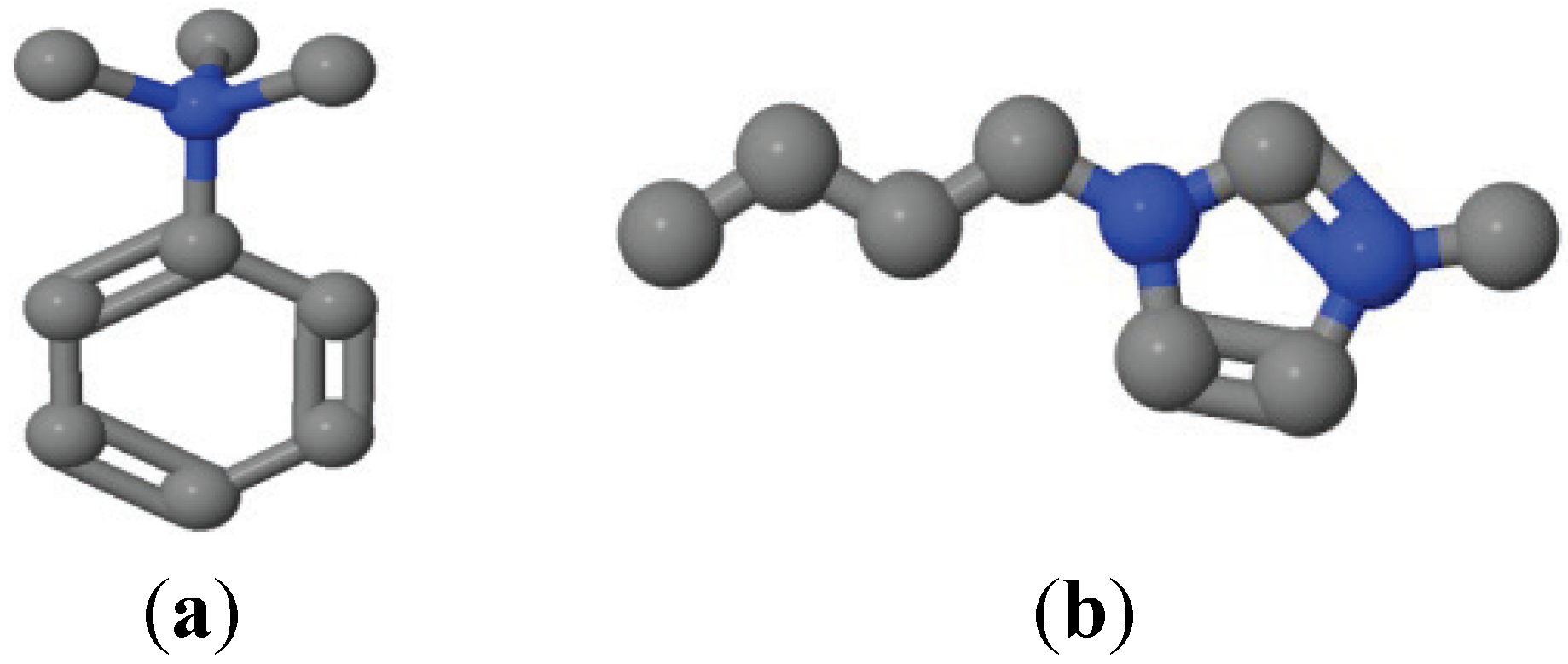
2.1. Materials

Samples of Nafion-112 protonated membrane from Dupont (Flagler County, FL, USA) with the following characteristics, nominal thickness of 51 μm, density 2000 kg/m3, ionic conductivity 8.3 S/m, acid capacity 0.89 meq/g and initial water content 5 wt%, were immersed in 1-butyl-3-methylimidazolium tetrafluoroborate (BMIM+BF4) or phenyltrimethylammonium chloride (TMPA+Cl) solutions for 24 h and Nafion-112/IL-doped membranes (Nafion112/BF4+ and Nafion112/TMPA+, respectively) were obtained by H+/IL-cation exchange mechanism [19], as it was extensively detailed in [2]. Since TMPA+Cl is not an ionic liquid (but it is common IL cation), an aqueous solution 40% (w/w) was used. Molecular weight (Mw) and molar volume (vm) of the studied IL-cations are: MwTMPA+ = 136 g/mol, vmTMPA+ = 189 cm3/mol, MwBMIM+ = 139 g/mol and vmBMIM+ = 182 cm3/mol, and their ball and stick models are indicated in Scheme 1. Membrane doping was performed at the laboratory of Joao Crespo, REQUIMTE/CQFB, FCT, Universidade Nova de Lisboa (Lisboa, Portugal). Membranes were removed from the solution after 24 h of contact with the RTILs and cleaned with paper tissue to remove any RTIL in the membrane surface and used for the different analyses.
Scheme 1. Ball and stick models of (a) phenyltrimethylammonium (TMPA+, (CH3)3NC6H5+), and (b) 1-butyl-3-methylimidazolium (BMIM+, C8H15N2+) IL-cations.
Applsci 04 00195 g007

2.2. XPS Measurements

Surface chemical characterisation of original and IL-doped membranes was performed by XPS. A Physical Electronics spectrometer (PHI 5700, Physical Electronics, Minneapolis, MN, USA) was used, with X-ray Mg Kα radiation (300W, 15 kV, 1253.6 eV) as the excitation source. High-resolution spectra were recorded at a given take-off angle of 45° by a concentric hemispherical analyser operating in the constant pass energy mode at 29.35 eV, using a 720 μm diameter analysis area. Under these conditions, the Au 4f7/2 line was recorded with 1.16 eV FWHM at a binding energy of 84.0 eV. The spectrometer energy scale was calibrated using Cu 2p3/2, Ag 3d5/2, and Au 4f7/2 photoelectron lines at 932.7, 368.3, and 84.0 eV, respectively. Charge referencing was done against –CF2-carbon of Nafion (C 1s, 292.0 eV). Membranes were mounted on a sample holder without adhesive tape and kept overnight at high vacuum in the preparation chamber before being transferred to the analysis chamber of the spectrometer for testing. Each spectral region was scanned several sweeps until a good signal to noise ratio was observed. The pressure in the analysis chamber was maintained lower than 5 × 10⁻⁶ Pa. PHI ACCESS ESCA-V6.0 F software (Physical Electronics, Minneapolis, MN, USA) package was used for acquisition and data analysis. A Shirley-type background was subtracted from the signals. Recorded spectra were always fitted using Gauss–Lorentz curves and following the methodology described in detail elsewhere [20], in order to determinate more accurately the binding energy (BE) of the different element core levels. Atomic concentration percentages of the characteristic elements of the surfaces were determined taking into account the corresponding area sensitivity factor [21] for the different measured spectral regions. Membrane samples were irradiated for a maximum time of 20 min to minimize possible X-ray damage.

2.3. Contact Angle Measurements

The hydrophobic/hydrophilic character of the membrane surfaces was determined from contact angles measurements, and they were performed with a Teclis (Lyon, France) T2010 instrument equipped with a video system. Membrane samples were mounted on glass slides to provide a flat surface for analysis. The drop method was used to measure the contact angle of de-ionized water on the surface of the membranes at ambient temperature.

2.4. Thermal Analysis

TG/DSC analysis was performed with a thermobalance TGA/DSC1 of Mettler (Schwerzenbach, Switzerland). A working air flow of 50 cm3/min was used for measurements carried out under most similar atmospheric conditions. The TG profile was collected in the 30 < T (°C) < 750 temperature range with a heating rate of 10 °C/min, using an open platinum pan of 70 μL. The thermal analysis was performed with dry samples of all the membranes with any pre-treatment.

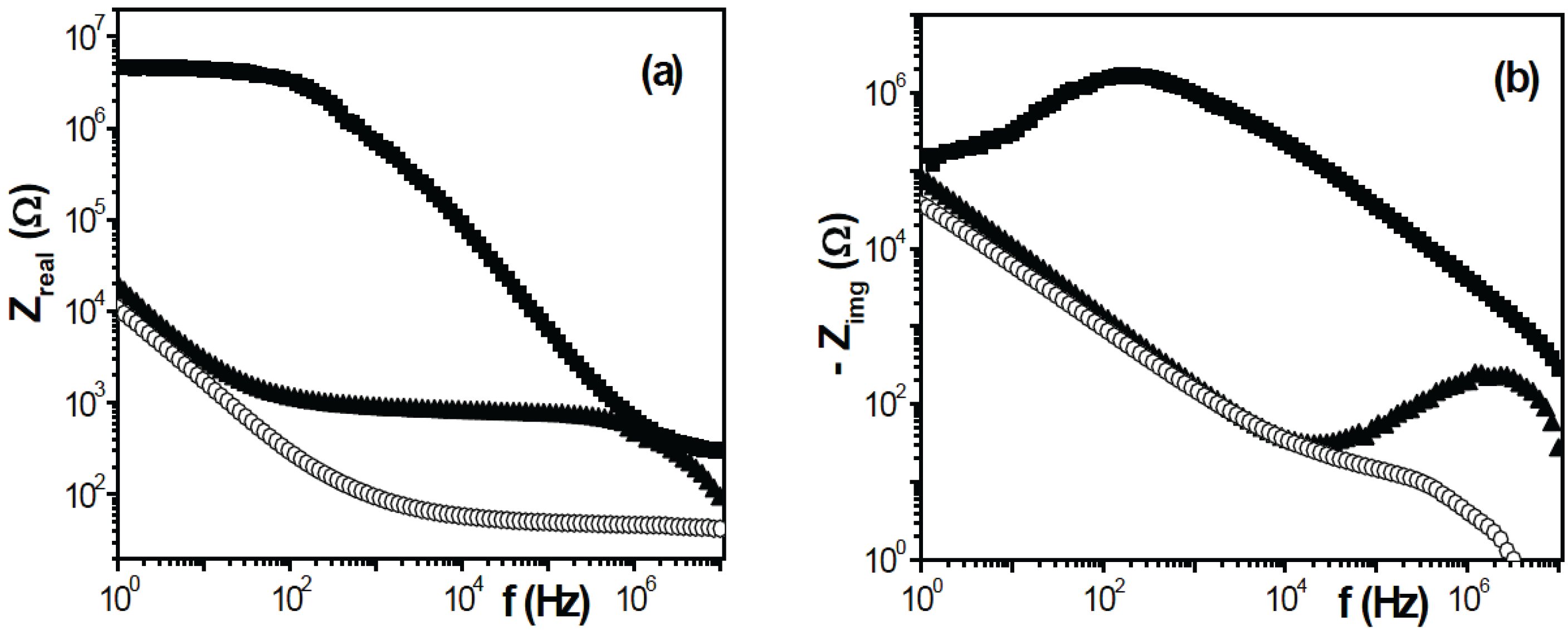
2.5. Impedance Spectroscopy Measurements

Impedance spectroscopy (IS) measurements with dry original (Nafion112) and ionic liquid doped samples (Nafion112/TMPA+ and Nafion112/BMIM+) were performed in a cell consisting of a Teflon support on which two Pt electrodes (2 cm × 2 cm) were placed and screwed down [22]. Electrodes were connected to a response Frequency Analyzer (Solartron 1260, Slough, UK) controlled by a computer. One hundred different frequencies in the range 1–107 Hz at a maximum voltage of 0.01 V were measured (electric field perpendicular to the membrane surface), and the experimental data were corrected by software, the influence of connecting cables and other parasite capacitances. Room temperature and atmospheric conditions during measurements were (25 ± 2) °C and ~45% humidity, respectively.

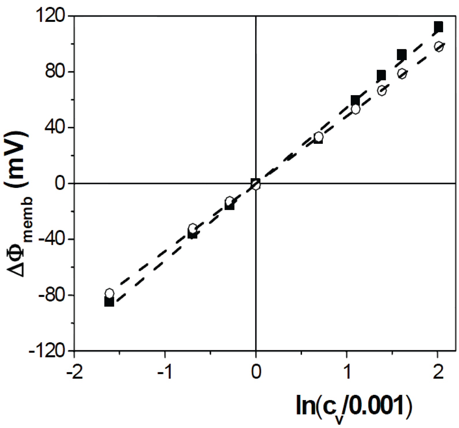
2.6. Membrane Potential Measurements

An electrochemical cell similar to that described in ref. [23] was used for membrane potential measurements. The membrane was placed in the middle of two symmetric half-cells, filled with HCl solutions of different concentrations (cf and cv), which were stirred by two Teflon-covered magnetic stirrers, one at the bottom of each half-cell with a stirring rate of 540 rpm, to minimize concentration-polarization at the membrane/solution interfaces [23]. A pair of reversible Ag/AgCl electrodes connected to a high impedance voltmeter was used for electromotive force ΔE measurements, which were carried out at room temperature (25 ± 2) °C and standard pH (5.8 ± 0.3) keeping constant the concentration of one of the HCl solutions (cf = 0.001 M) and gradually varying the concentration of the solution at the other half-cell (5 × 10⁻⁴ M ≤ cv ≤ 7.5 × 10⁻³ M). Cell concentration reaches the maximum cell concentration [24]: ΔEmax = −(2RT/F) ln(cv/cf)

3. Results and Discussion

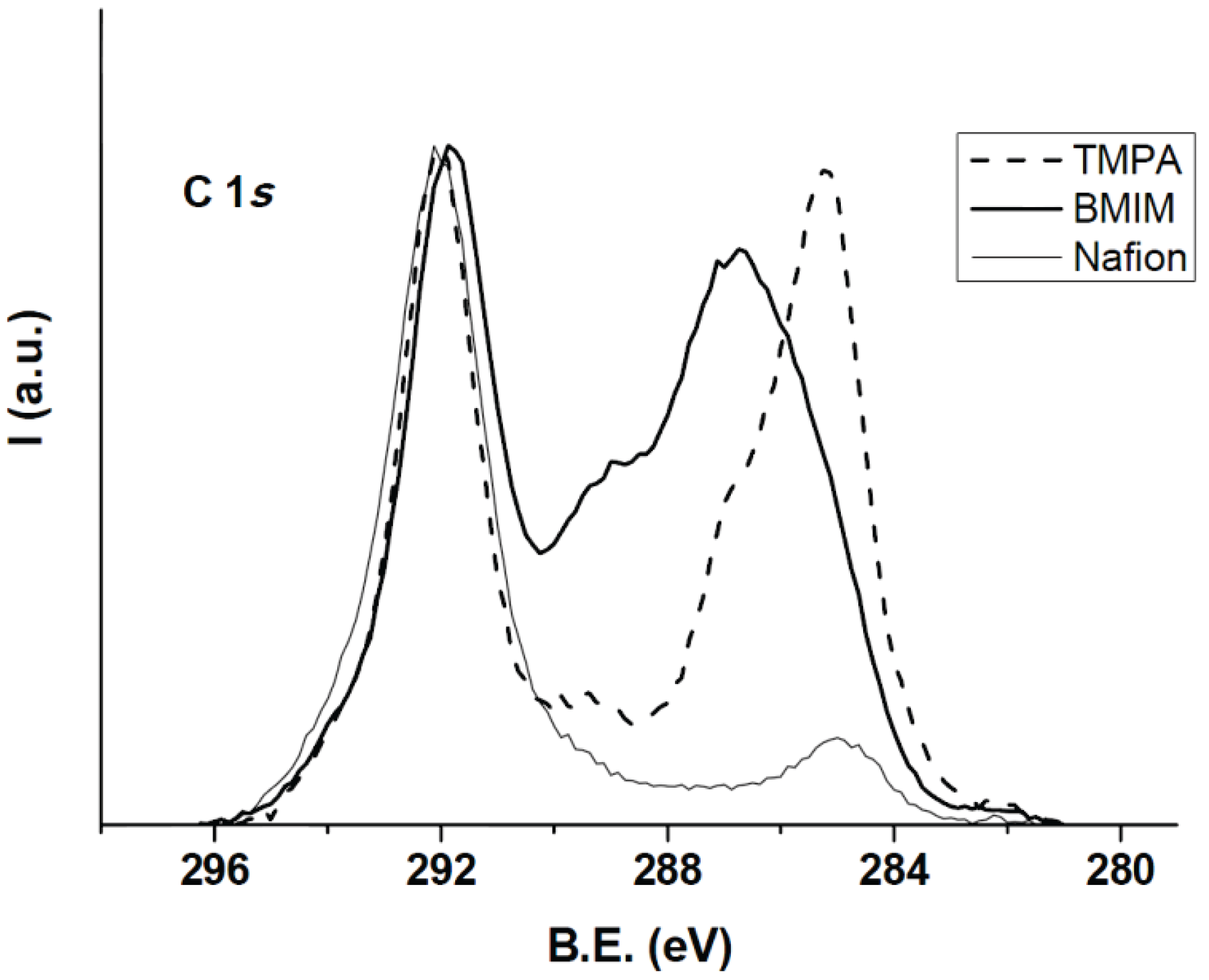
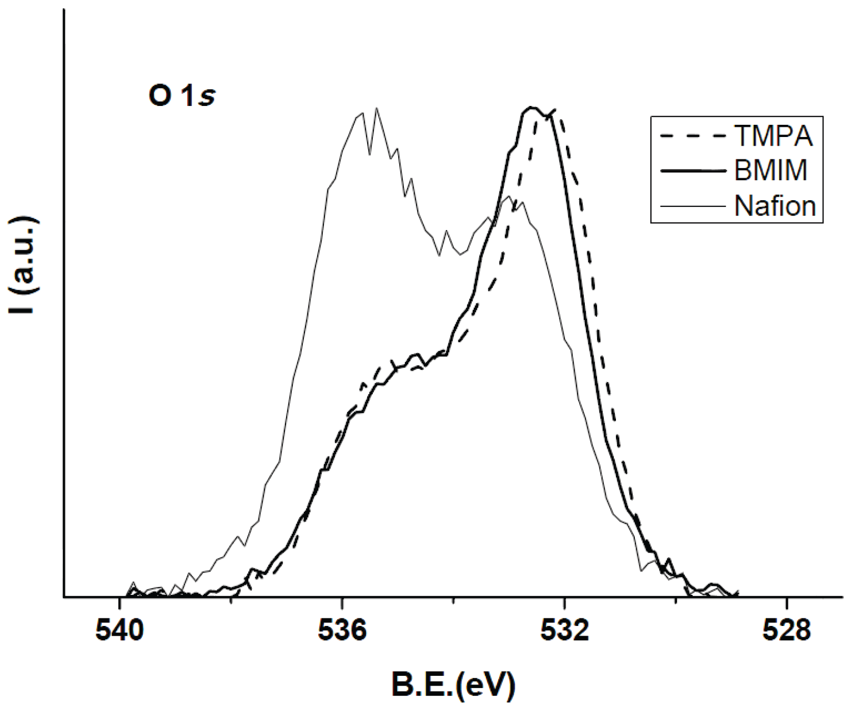
3.1. Membrane Surface Characterization

Surface chemical changes associated to ILs doping of Nafion112 membrane was studied by XPS analysis, which allows the determination of the atomic concentration percentage (A.C.%) of the elements present on the membranes surfaces. Table 1 presents the atomic concentration percentages (A.C.%) of the characteristic elements (C 1s, O 1s, F 1s, S 2p and N 1s) found on the surfaces of the studied membranes, which were obtained from high resolution spectra of the main photoelectron peaks, as well as the Nafion theoretical values according to its formulae [2]. Small percentages (<0.5%) of other elements such (chlorine, silicon, etc.) also found are not indicated since they are associated to surface contamination.
Table 1. Atomic concentration percentages of the characteristic elements found on the membrane surfaces.
SampleC%O%F%S%N%
Nafion (theoretical) 30.87.760.01.5-
Nafion11239.06.653.41.00.2
Nafion112/TMPA+45.67.044.21.01.3
Nafion112/BMIM+47.94.842.30.93.6
As it can be observed in Table 1, the comparison of theoretical and experimental values for the Nafion membrane only shows slight differences, which are attributed to surface contamination, particularly to the presence of adventitious carbon. The reduction of fluorine concentration (Nafion characteristic element) in Nafion112/TMPA+ (17%) and Nafion112/BMIM+ (21%) doped membranes is an indication of membrane surface coverage by the ILs, which is also supported by the increase in the nitrogen A.C.%. The lower the fluorine concentration, the lower is the hydrophobic character. This means that according to these values, the Nafion112/BMIM+ sample must show the lower hydrophobic character. This point can be discriminated by considering the XPS spectra, which provide information on the chemical interactions among the different elements on the solid surface. As expected, the N atomic concentration% was higher for sample Nafion112/BMIM+ that presents two nitrogen atoms per formula.
Figure 1 shows the C 1s core level normalized spectra of Nafion112, Nafion112/BMIM+ and Nafion112/TMPA+ doped membranes. The higher relative intensity of the contributions at low binding energy (284.0–288 eV) observed in samples Nafion112/BMIM+ and Nafion112/TMPA+ are due to the presence of phenyl and alkyl groups of the IL cations.
Figure 1. Comparison of the C 1s core level spectra obtained for Nafion112, Nafion112/BMIM+ and Nafion112/TMPA+ doped membranes.
Applsci 04 00195 g001
Table 2 lists the decomposition of the C 1s spectra of the studied membranes in five contributions that are assigned as follows: C1 to adventitious carbon and phenyl moiety in the case of TMPA+ and the alkyl chain in the case of BMIM+; C2 to carbons linked to nitrogen; C3, C4 and C5 are assigned to carbons bonded to fluorine of the Nafion membranes. It is clear that upon the incorporation of the IL cations, the sum of C1 and C2 are 52.43% and 42.03% for Nafion112/TMPA+ and Nafion112/BMIM+, respectively, while this sum is only 11.68% for Nafion112. This surface analysis supports the surface incorporation of the ILs cations and the correspondent decrease of the percentages of the contributions C4 and C5. This incorporation suggests a decrease in hydrophobic character.
Table 2. Decomposition of the C 1s spectra (in %) for Nafion112, Nafion112/BMIM+ and Nafion112/TMPA+ doped membranes.
SampleC1C2C3C4C5
Nafion1128.053.638.3769.7010.20
Nafion112/TMPA+36.9215.518.2936.302.97
Nafion112/BMIM+14.0128.0522.9631.563.42
C1 (284.8 eV), C2 (286.9 eV), C3 (289.4 eV), C4 (292.0 eV), C5 (293.7 eV).
The normalized O 1s core level spectra of the studied membranes (see Figure 2) indicate that the incorporation of the IL cations produces a decrease of the relative intensity of the contributions at high binding energy due to oxygen from polyether chain. This is due to the covering effect of the IL cations. However, the relative intensity of the contributions at low binding energy (about 532.0 eV) derived from the presence of sulphonic groups is maintained. That is, polar IL cations interact with the hydrophilic part of the Nafion membrane.
Figure 2. Comparison of the O 1s core level spectra obtained for Nafion112, Nafion112/BMIM+ and Nafion112/TMPA+ doped membranes.
Applsci 04 00195 g002
As indicated above, surface modification of the Nafion membranes associated with the incorporation of the IL-cation might also affect its hydrophobic character, which was determined by contact angle measurements. Table 3 shows average contact angle values obtained from measurements performed for both surfaces of the studied membranes. As can be observed practically, the same values were obtained for both ILs-doped membranes, which present more hydrophilic character than original Nafion112 sample, in agreement with XPS results.
Table 3. Average values of the contact angles for original and IL-modified membranes.
MembraneAverage contact angle (°)
Nafion11291 ± 2
Nafion112/TMPA+74 ± 8
Nafion112/BMIM+72 ± 6

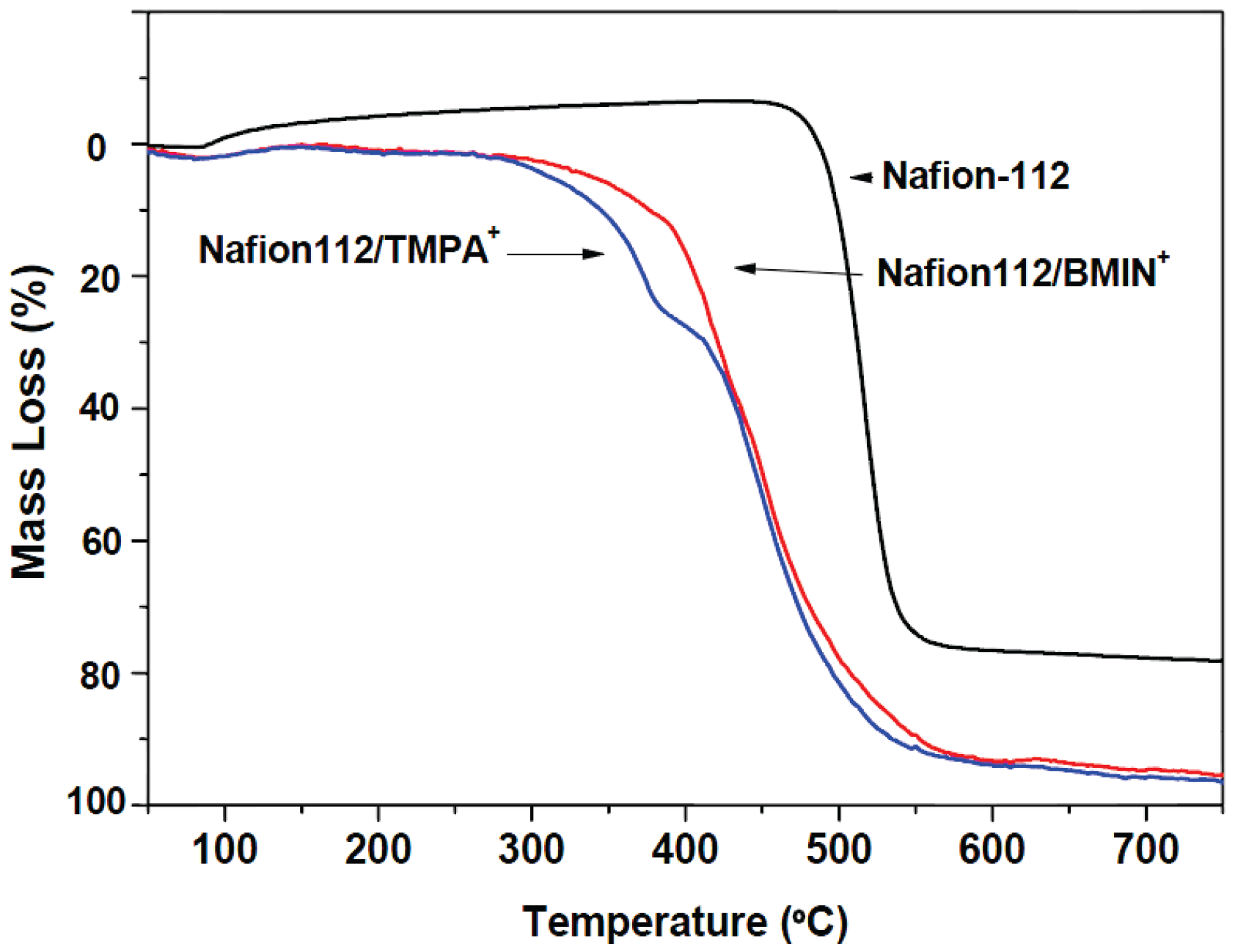
3.2. Thermal Characterization of Original and IL-Cations Doped Membranes

TG-DSC analysis in N2 and air indicates the relatively high stability of the samples Nafion112/BMIM+ and Nafion112/TMPA+ in comparison with the Nafion112 membrane. The doped membranes are stable up to 300 °C and 325 °C in the cases of Nafion112/TMPA+ and Nafion112/BMIM+, respectively. Figure 3 shows the TG curves in N2 atmosphere as an illustrative example. DSC curves show two marked exothermal effects between 450 and 600 °C for Nafion112/BMIM+ and Nafion112/TMPA+ doped membranes due to the pyrolysis of the ionic liquid. A weak exothermal effect is observed at a much higher temperature range in the case of Nafion112 (550–650 °C).
Figure 3. TG profiles for Nafion112, Nafion112/BMIM+ and Nafion112/TMPA+ doped membranes.
Applsci 04 00195 g003

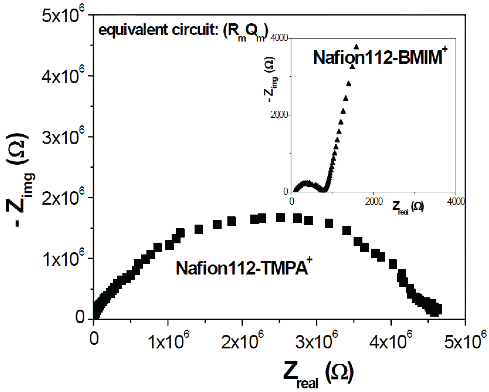
3.3. Electrical Characterization of Nafion112/IL-Cations Doped Membranes

Electrical changes associated to IL-cation doping on Nafion-112 membrane were determined from impedance spectroscopy measurements performed with dry samples (Nafion112/TMPA+ and Nafion112/BMIM+). Figure 4 shows a comparison of the Nyquist plot (−Zimag vs. Zreal) obtained for both doped samples, where significant differences can be observed. In both cases, the electrical response is a depressed semicircle, and the associate equivalent circuit corresponds to a parallel association of a resistance (Rm) and a constant phase element or non-ideal capacitor (Qm) [15].
Figure 4. Nyquist plot (−Zimg vs. Zreal) for Nafion112-TMPA+ (■) and Nafion112-BMIN+ (▲) dry samples.
Applsci 04 00195 g004
Figure 5 shows a comparison of Bode diagrams (Zreal vs. frequency, Figure 5a and −Zimag vs. frequency, Figure 5b) for both ILs-cation doped membranes, Nafion112/TMPA+ and Nafion112/BMIM+, as well as the original Nafion-112 sample. As can be observed, significantly lower values for the real part of the impedance (directly related to electrical resistance) were obtained for the original Nafion-112 membrane in comparison with both IL-cations doped samples (almost 20 times higher for Nafion112/BMIM+, but several orders of magnitude for Nafion112/TMPA+). Another significant point is the shift to lower frequency value (~400 Hz) of the maximum relaxation frequency obtained for the Nafion112/TMPA+ membrane with respect to both Nafion-112 and Nafion112/BMIM+ membranes, which use to be associated to more compact membrane structure [18].
Figure 5. Bode plots: (a) Zreal vs. frequency and (b) −Zimg vs. frequency, for dry Nafion-112 (o), Nafion112-TMPA+ (■) and Nafion112-BMIM+ (▲) membranes.
Applsci 04 00195 g005
Due to the very similar molar volume of both cations, differences in electrical behaviour could be associated with the different shapes of both cations, sphere-like for TMPA+ and lineal for BMIM+ (see Scheme 1), which might facilitate the inclusion of the latter into the pinholes observed in the structure of the Nafion-112 membrane [25,26], but causing partial blockage when quasi-spherical TMPA+ cation is used for membrane doping. In this context, it should also be mentioned the significant reduction (around two orders of magnitude) in methanol cross-over reported for both Nafion112/TMPA+ and Nafion112/BMIM+ membranes when compared with the original Nafion-112 sample [11], which can be of great interest for membranes’ application in direct methanol fuel cells.
Taking into account the more similar electrical response obtained for dry Nafion112/BMIM+ doped membrane and the original Nafion-112 one, electrochemical characterization by determining counter-ions’ transport through both samples in wet conditions (contact with HCl-aqueous solutions) was performed with these two samples [27]. Membrane potential, ΔΦmemb, is the electrical potential difference between both sides of a membrane separating two solutions of the same electrolyte but different concentrations (c1 and c2) [28]. Figure 6 shows the variation of membrane potentials with the logarithm of the solution concentrations ratio for Nafion-112 and Nafion112/BMIM+ membranes, where a practically linear relationship can be observed.
Figure 6. Membrane potentials versus HCl solutions concentrations ratio for Nafion-112 (o) and Nafion112/BMIM+ (■) membranes.
Applsci 04 00195 g006
Ion transport number (ti) is the parameter commonly used to characterize the effect of membrane charge on the transport of ions since it represents the fraction of the electric current transported by an ion i (ti = Ii/IT, then ∑i ti = 1; t+ + t = 1 for single salts), and consequently, for an ideal cation-exchanger membrane t+ = 1. t+ values for both membranes were determined from membrane potential by the following expression [28,29]: t+ = ΔEEmax. Average values of H+ transport number across Nafion-112 and Nafion112/BMIM+ membranes for the whole interval of HCl concentrations are: <t+(Nafion-112) ≥ (0.938 ± 0.019) and <t+(Nafion112/BMIM+) ≥ (0.978 ± 0.011). According to these results only slight differences between wet samples of both kinds of membranes seems to exist, but BMIM+ doping of Nafion-112 membrane slightly favours proton transport.

4. Conclusions

The effect of Nafion-112 membrane doping by incorporation of two IL-cations (1-butyl-3-methylimidazolium tetrafluoroborate or BMIM+BF4 and phenyltrimethylammonium chloride or TMPA+Cl) with similar molecular weight and molar volume by proton/cation exchange mechanism was analyzed.
Surface, thermal and electrical characterizations of the Nafion112 doped membranes were basically carried out by XPS, contact angle, DSC and impedance spectroscopy measurements. Results show the surface coverage of Nafion112 as a result of both BMIM+ and TMPA+ doping, which reduced the hydrophobic character of both modified membranes and give rise to thermal stable membranes when compared with the original Nafion112 membrane. However, membrane doping reduces the conductivity of both modified samples, but this effect is significantly higher for the Nafion112/TMPA+ membrane. Although this result does not seem to favor the use of doped membranes in PMEFCs systems, it could be of interest in DMFCs due to a reduction in methanol cross-over.
Diffusive transport of HCl solutions through Nafion112/BMIM+ membrane was also analyzed by membrane potential measurements and compared with the original Nafion112 sample. Our results indicate a slightly higher transport number of H+ across the doped Nafion112/BMIM+ membrane, which can also be of interest for application in other electrochemical devices.

Acknowledgments

Virgina Romero acknowledges the financial support to MICINN, Spain, through the FPU scholarship. The authors thank Joao Crespo, Maria Isabel Coelhoso and Luisa Neves, Department of Chemical Engineering at the Universidade Nova de Lisboa for their supervision and help during cation-incorporation in membranes measurements, and to CICYT (Project CTQ2011-27770, FEDER funds) and projectCTQ2012-37925-C03-03 (Ministry of Economy and Competitiveness, Spain and FEDER funds), for financial support.

Conflicts of Interest

The authors declare no conflict of interest.

References

  1. Einsenberg, A.; Yeager, H.L. Perfluorinated Ionomer Membranes, ACS Symposium Series; American Chemical Society (ACS): Washington, DC, USA, 1982; Volume 180. [Google Scholar]
  2. De Yuso, M.V.M.; Neves, L.A.; Coelhoso, I.M.; Crespo, J.G.; Benavente, J.; Rodríguez-Castellón, E. A Study of Chemical Modifications of a Nafion Membrane by Incorporation of Different Room Temperature Ionic Liquids. Fuel Cells 2012, 12, 606–612. [Google Scholar] [CrossRef]
  3. Lojoiuo, C.; Martinez, M.; Hanna, M.; Molmeret, Y.; Cointeaux, L.; Leprêtre, J.-C.; El Kissi, N.; Guidet, J.; Judeinstein, P.; Sanchez, J.-Y. PILs-based Nafion Membranes: A Route to High-temperature PEFMCs Dedicated to Electric and Hybrid Vehicles. Polym. Adv. Technol. 2008, 19, 1406–1414. [Google Scholar] [CrossRef]
  4. Doyle, M.; Choi, S.; Proulx, G. High-Temperature Proton Conducting Membranes Based on Perfluorinated Ionomer Membrane-Ionic Liquid Composites. J. Electrochem. Soc. 2000, 147, 34–37. [Google Scholar]
  5. Schmidt, C.; Glück, T.; Schmidt-Naake, G. Modification of Nafion Membranes by Impregnation with Ionic Liquids. Chem. Eng. Technol. 2008, 31, 13–22. [Google Scholar] [CrossRef]
  6. Bennet, M.D.; Leo, D.J. Ionic liquids as Stable Solvents for Ionic Polymer Transducers. Sens. Actuators A 2004, 115, 79–90. [Google Scholar] [CrossRef]
  7. Welton, T. Room-Temperature Ionic Liquids. Solvents for Synthesis and Catalysis. Chem. Rev. 1999, 99, 2971–2984. [Google Scholar] [CrossRef]
  8. Armand, M.; Endres, F.; MacFarlane, D.R.; Ohno, H.; Scrosati, B. Ionic-liquid Materials for the Electrochemical Challenges of the Future. Nat. Mater. 2009, 621–629. [Google Scholar]
  9. Bonhôte, P.; Dias, A.P.; Papageorgiou, N.; Kalyanasundaram, K.; Grätzel, M. Hydrophobic, Highly Conductive Ambient-Temperature Molten Salts. Inorg. Chem. 1996, 35, 1168–1178. [Google Scholar] [CrossRef]
  10. Neves, L.; Benavente, J.; Coelhoso, I.M.; Crespo, J.G. Design and Characterisation of Nafion Membranes with Incorporated Ionic Liquids Cations. J. Membr. Sci. 2010, 347, 42–52. [Google Scholar] [CrossRef]
  11. Neves, L.A.; Crespo, J.G.; Coelhoso, I.M. Gas Permeation Studies in Supported Ionic Liquid Membranes. J. Membr. Sci. 2010, 357, 160–170. [Google Scholar] [CrossRef]
  12. Martinez, M.; Molmeret, Y.; Cointeaux, L.; Iojoiu, C.; Leprêtre, J.C.; El Kissi, N.; Judeinstein, P.; Sanchez, J.Y. Proton-conducting Ionic Liquid-based Proton Exchange Membrane Fuel Cell membranes: The Key Role of Ionomer-ionic Liquid. J. Power Sources 2010, 195, 5829–5839. [Google Scholar] [CrossRef]
  13. Ariza, M.J.; Benavente, J.; Rodríguez-Castellón, E. The Capability of X-ray Photoelectron Spectroscopy in the Characterization of Membranes: Correlation between Surface Chemical and Transport Properties in Polymeric Membranes. In Handbook of Membranes: Properties, Performance and Applications; Nova Science Publishers, Inc.: New York, NY, USA, 2009; pp. 257–290. [Google Scholar]
  14. Fortunato, R.; Afonso, C.A.M.; Benavente, J.; Rodriguez-Castellón, E.; Crespo, J.G. Stability of Supported Ionic Liquid Membranes as Studied by X-ray Photoelectron Spectroscopy. J. Membr. Sci. 2005, 256, 216–223. [Google Scholar]
  15. Macdonalds, J.R. Impedance Spectroscopy; Wiley: New York, NY, USA, 1987. [Google Scholar]
  16. Asaka, K. Dielectric Properties of Cellulose Acetate Reverse Osmosis Membranes in Aqueous Solution. J. Membr. Sci. 1990, 50, 71–84. [Google Scholar] [CrossRef]
  17. Mijovic, J.; Bellucci, F. Impedance Spectroscopy of Reactive Polymers. Trends Polym. Sci. 1996, 4, 74–82. [Google Scholar]
  18. Benavente, J. Use of impedance spectroscopy for characterization of membranes and the effect of different modifications. In Membrane Modification: Technology and Applications; Hilal, N., Khayet, M., Wright, C.J., Eds.; CRC Press: Boca Raton, FL, USA, 2012; pp. 21–40. [Google Scholar]
  19. Shäfer, T.; di Paolo, R.E.; Franco, R.; Crespo, J.G. Elucidating Interaction of Ionic Liquids with Polymer Films Using Confocal Raman Spectroscopy. Chem. Commun. 2005, 2594–2596. [Google Scholar]
  20. Ariza, M.J.; Benavente, J.; Rodríguez-Castellón, E.; Palacio, L. Effect of Hydration of Polyamide Membranes on the Surface Electrokinetic Parameters: Surface Characterization by X-ray Photoelectronic Spectroscopy and Atomic Force Microscopy. J. Colloid Interface Sci. 2002, 247, 149–158. [Google Scholar] [CrossRef]
  21. Moulder, J.F.; Stickle, W.F.; Sobol, P.E.; Bomben, K.D. Handbook of X-ray Photoelectron Spectroscopy; Chastain, J., Ed.; Perkin-Elmer Corporation: Minneapolis, MN, USA, 1992. [Google Scholar]
  22. Ramos, J.D.; Milano, C.; Romero, V.; Escalera, S.; Alba, M.C.; Vázquez, M.I.; Benavente, J. Water Effect on Physical-chemical and Elastic Parameters for a Dense Cellulose Regenerated Membrane. Transport of Different Aqueous Electrolyte Solutions. J. Membr. Sci. 2010, 352, 153–159. [Google Scholar] [CrossRef]
  23. Pelaez, L.; Vázquez, M.I.; Benavente, J. Interfacial and Fouling Effects on Diffusional Permeability Across a Composite Ceramic Membrane. Ceramics Int. 2010, 36, 797–801. [Google Scholar] [CrossRef]
  24. Mallevialle, J.; Odendaal, P.E.; Wiesner, M.R. Water Treatment Membrane Processes; McGraw-Hill: Chicago, IL, USA, 1996. [Google Scholar]
  25. Unemura, K.; Wang, T.; Hara, M.; Kuroda, R.; Uchida, O.; Nagai, M. Nono-characterization of a Nafion Thin Film in Air and in Water by Atomic Force Micorscopy. IOP Publ. J. Phys. 2007, 61, 1202–1206. [Google Scholar]
  26. De Yuso, M.V.M.; Cuberes, M.T.; Romero, V.; Neves, L.; Coelhoso, M.I.; Crespo, J.G.; Rodríguez-Castellón, E.; Benavente, J. Modification of a Nafion Membrane by n-dodecyltrimethylammonium Cation Inclusion for Potential Application in DMFC. Int. J. Hydrog. Energy 2014, 39, 4023–4029. [Google Scholar] [CrossRef]
  27. Romero, V.; Vega, V.; García, J.; Zierold, R.; Nielsch, K.; Prida, V.M.; Hernando, B.; Benavente, J. Changes in morphology and ionic transport induced by ALD SiO2 coating of nanoporous alumina membranes. ACS Appl. Mater. Interfaces 2013, 5, 3556–3564. [Google Scholar] [CrossRef]
  28. Lakshminarayanaiah, N. Transport Phenomena in Membranes; Academic Press: New York, NY, USA, 1969. [Google Scholar]
  29. Benavente, J. Electrochemical impedance spectroscopy as a tool for characterization of membranes in contact with electrolyte solutions in Surface Electrical Phenomena. In Membranes and Microchannels; Szymczyk, A., Ed.; Transworld Reserach Network: Rennes, France, 2008. [Google Scholar]

