Review

New Trends in Dental Biomechanics with Photonics Technologies

1
INESC-Porto and Faculty of Sciences of the University of Porto (FCUP), Rua do Campo Alegre, 687, Porto 4150-179, Portugal
2
CIDESD-ISMAI, Institute University of Maia, Avenida Carlos Olviveira, Castelo da Maia, Porto 4475-690, Portugal
3
Centre for Mechanical Technology and Automation (TEMA), Department of Mechanical Engineering, University of Aveiro, Campus Universitário de Santiago, Aveiro 3810-193, Portugal
*
Author to whom correspondence should be addressed.
These authors contributed equally to this work.
Appl. Sci. 2015, 5(4), 1350-1378; https://doi.org/10.3390/app5041350
Submission received: 31 July 2015 / Revised: 24 September 2015 / Accepted: 25 September 2015 / Published: 24 November 2015
(This article belongs to the Special Issue Feature Papers)

Abstract

:
Engineering techniques used to evaluate strain-stress fields, materials’ mechanical properties, and load transfer mechanisms, among others, are useful tools in the study of biomechanical applications. These engineering tools, as experimental and numerical ones, were imported to biomechanics, in particular in dental biomechanics, a few decades ago. Several experimental techniques have been used in dental biomechanics, like photoelasticity, ESPI (Electronic Speckle Pattern Interferometry), strain gages, and other kinds of transducers. However, these techniques have some limitations. For instance, photoelasticity and ESPI give the overall field pattern of the strain, showing the stress-strain concentration points. These methods cannot give an accurate measurement at all points. On the contrary, strain gages can be used to perform local measurements. However, as they use electrical resistances, their use is limited to perform in vivo measurements. Optical fiber sensors have already been used in dentistry, for diagnostic and therapeutic purposes, and in dental biomechanics studies. Lasers have also been used in clinical dentistry for a few decades. Other optical technologies, like optical coherence tomography (OCT), became suitable for dental practice and nowadays it is perhaps one that has had more development in dentristry, along with lasers.

1. Introduction

Biomechanics is closely related to engineering because it often uses traditional engineering sciences to analyze biological systems. Applied mechanics, such as continuum mechanics, mechanism analysis, structural analysis, kinematics, and dynamics play an important role in the study of biomechanics. Leonardo da Vinci (1452–1519) is considered the “Father” of modern biomechanics. He was primarily concerned in the anatomy of the human body and he was also interested in the study of movement, so his work was full of anatomical drawings of the musculoskeletal system.
With regard to dentistry, the French surgeon Pierre Fauchard (1678–1761) is known as the “father of modern dentistry”. Despite the limitations of the primitive surgical instruments during the late 17th and early 18th centuries, Fauchard was a highly-skilled surgeon who started to make remarkable dental instruments, often adapting tools from watchmakers, jewelers, and even barbers. He introduced dental fillings as treatment for dental cavities; he was the pioneer of dental prosthesis, discovering many methods to replace lost teeth. His main contributions to dental science consist primarily of his publication in 1728 called “Le chirurgien dentist” [1]. Dentistry has depended upon physical replicas, such as plaster casts and models, to duplicate the human dentition and anatomical parts for the diagnosis of oral pathology, and for the fabrication of dental prostheses. The application of modern optical techniques for remote measurement may provide alternate, improved treatment methodologies, including the acquisition of data suitable for computer analysis and numerical-controlled automated prostheses fabrication [2]. Usually, biological systems are much more complex than human-built systems. Numerical methods are hence applied in almost every biomechanical study. Research is done in an iterative process of hypothesis and verification, including several steps of modeling, computer simulation, and experimental measurements. The development of all the technologies can play a key important role to achieve better diagnostic methods, clinical and surgical methods, as well as to better understand the biomechanics of the entire stomatognatic system and everything related to it.
In this paper, a brief description of other non-optical technologies is presented and some examples are given. The greatest emphasis was put on photonic technologies and in their application in dental biomechanics and in dentistry in general. The photonic technologies, such as photoelasticity, Moiré fringe pattern, electronic speckle pattern interferometry (ESPI), lasers, optical coherence tomography (OCT), and optical fiber sensors (FOS) are presented and for each one is given the principal features of their working principles and some examples of ongoing research and performed studies are offered.

2. Conventional Technologies

The application of tribology in dentistry is an important research field and it has been developed an understanding of it for successful design and selection of artificial dental materials [3]. Likewise, stress/strain analyses is very important in dental biomechanics, because it is important for the design of implants, prostheses, and orthodontic appliances, among others. Stress/strain analysis can be made either experimentally or by finite element analysis (FEA). Most often, these two methodologies are carried out simultaneously within the same study because they can give complementary information and can also serve for validation. FEA can give full-field information of the stress/strain pattern, but experimental methods only give information at the sensor’s location.
The gold standard of conventional sensors for stress/strain analysis is the strain gage (SG). This sensor is based in the property that relates the variation of electrical resistance with respect to strain. Although their technology is very well established, with some good properties representing advantages in regard to other technologies, they also have disadvantages—mostly related to possible applications for in vivo measurements and in clinical practice. Strain sensors can also be piezoresistive or with other kinds of solid-state properties.
FEA is based in the creation of a computer model of the anatomical dental structures and all kind of dental devices and, after that, is simulated in computer. For the simulation the materials’ mechanical properties, mechanical loads representing physiological function, and boundary conditions are necessary. Biological tissues and, in particular, dental tissues, are quite a challenge to characterize their properties. Additionally, the real values of physiological loads must be obtained experimentally and are not always easy to measure. Mainly due to these constraints, the biomechanical studies are carried out in vitro.
In literature studies can be found using SG to evaluate the strains in restored teeth, in prosthodontics, and endodontics [4,5]. The same sensors were also used to characterize dental materials [6]. Other studies are reported in literature about the study of biomechanics of dental implants [7,8] and in dental prostheses [9], by means of SG. Universal testing machines, nanoindentation, and customized machines were used to characterize and obtain the mechanical properties of dental materials [10,11,12,13,14].
Numerical models were used to perform in vitro evaluation of the strain pattern inside dental hard tissues and the way the loads are transmitted through them [15]. FEM was applied to investigate the residual shrinkage stress distributions in dental materials [16,17]. Other studies are related to the simulation of dental implant biomechanics, related to the osteointegration and load mechanism transfer in dental implant-supported prostheses [18,19,20]. This methodology was also applied in prosthodontic and endodontic studies [21,22,23].

3. Photonic Technologies

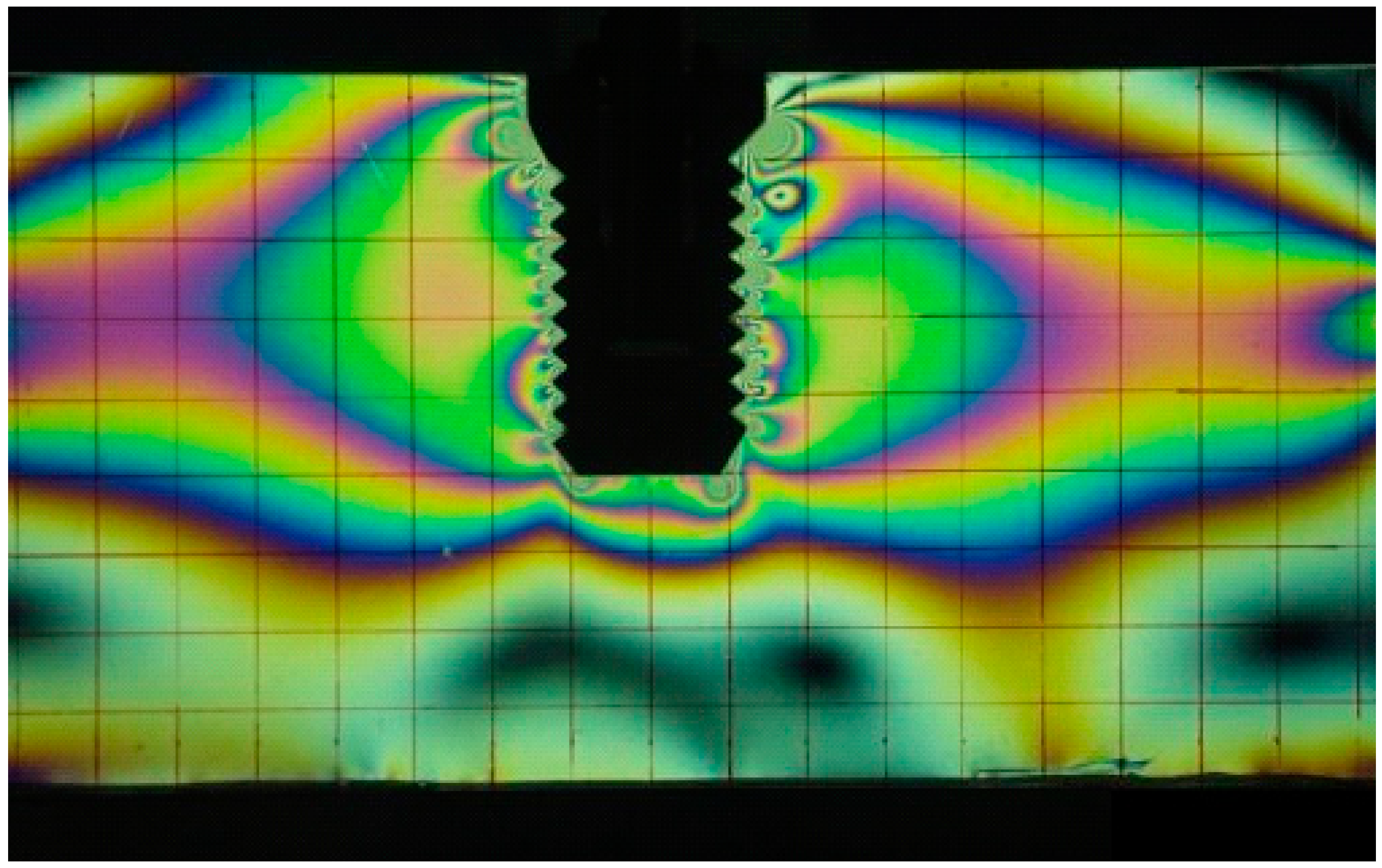
3.1. Photoelasticity

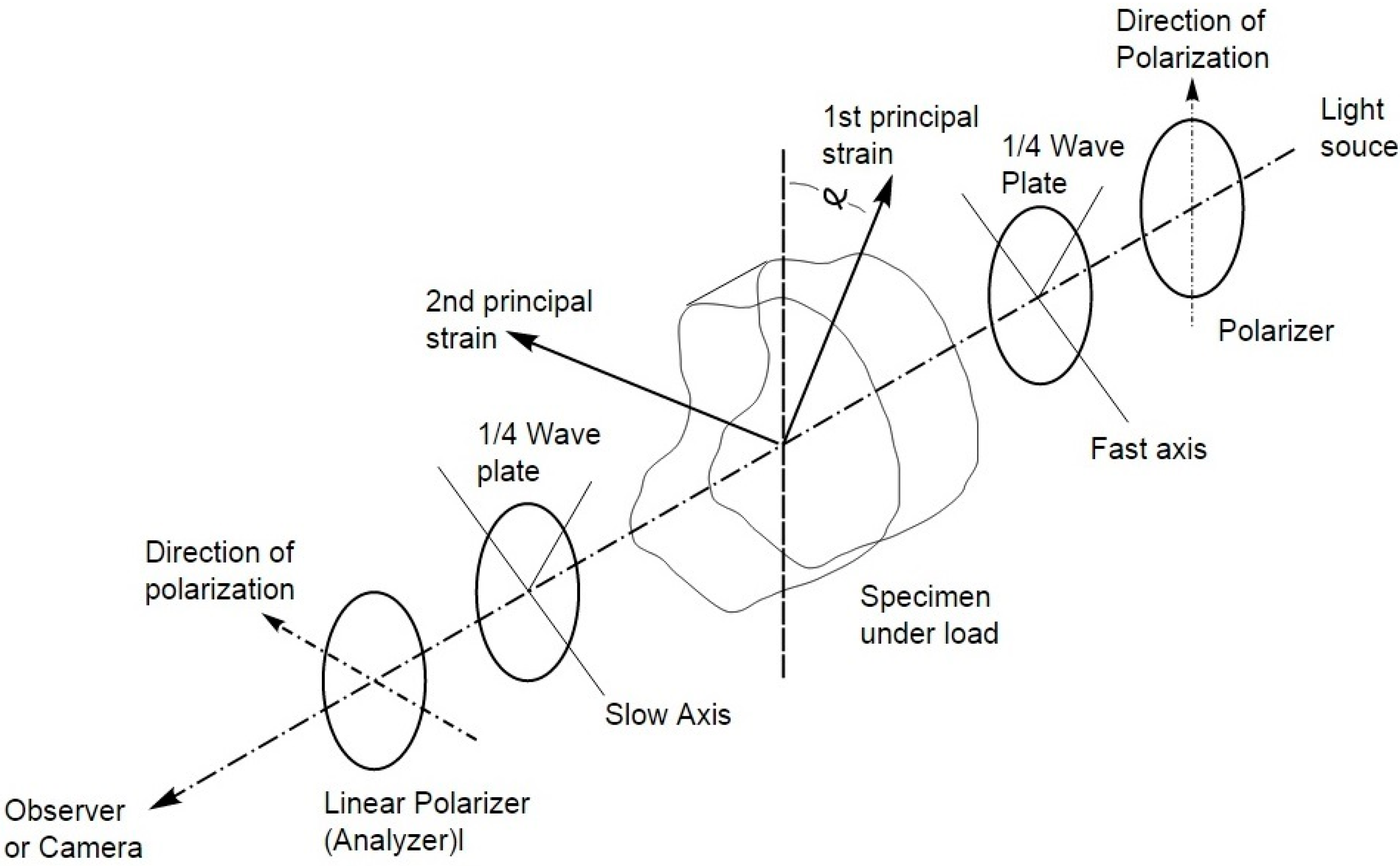
3.1.1. Working Principles

Photoelasticity is one of the oldest methods used for experimental stress analysis. The method relies on the birefringence property exhibited by transparent materials, under the influence of external loading. The principles of photoelasticity can be succinctly described by:
  • For stress (or strain) induced birefringence, the normally-incident polarized light is split into two components along the principal stress directions in a plane perpendicular to the direction of light propagation and are transmitted only along these planes through the model.
  • The velocities of light transmission along these directions are directly proportional to the intensities of the respective principal stresses.
This means that the input linearly-polarized light emerges as an elliptical polarized light, where the eccentricity depends on the principal stress directions and their magnitudes. By the Maxwell Stress Optic Law, a change in load induced in two components, aligns with the principal stress directions, with different refractive indexes. The induced difference in the refractive indices leads to a relative phase retardation between the two components, which is linearly proportional to the principal stress components and is given by Equation (1) as:
α λ 2 π l 1 C = ( σ 1 σ 2 )
where α is the phase difference between the two components, λ is the wavelength of light, C is the relative stress optic coefficient; l is the distance the light traverses through the model and σ1 and σ2 are the two principal stress components. The number of fringe order N can be calculated by Equation (2):
N = α 2 π
The required phase difference or fringe order is determined by placing the birefringent model in a circular polariscope, as schematized in Figure 1.
The fringe pattern can have dark lines, corresponding to points where the intensity of light is zero, called isoclinics and colored lines called isochromatics. Isoclinic lines provide information on the principal directions of stresses throughout the model. Isochromatics correspond to lines of constant principal stress difference (lines with the same color).
The basic advantage of a circular polariscope over a plane polariscope is that in a circular polariscope setup we only get the isochromatics and not the isoclinics. This eliminates the problem of differentiating between the isoclinics and the isochromatics. In a standard plane polariscope both the isoclinics and isochromatics are shown.
Figure 1. Schematic representation of a circular polariscope.
Applsci 05 01350 g001

3.1.2. Dental Applications

Photoelasticity was for the first time used in dentistry by Zak [24] to study different types of orthodontic movements. Late in the 1940s this method was used in the solution of dental problems with regard to structural design by Noonan [25], Castro, and King [26]. The general procedure is to construct a model of the structure to be investigated from what is known as a photoelastic material. The direction and magnitude of the applied forces on the model, the way in which the model is supported, and the shape of the model must be similar to the conditions of the actual structure. The internal stresses in the model will then be similar to those existing in the actual structure regardless of material [26,27,28]. Photoelasticity has been used in a wide number of dental biomechanical studies [29]. It has been applied in 2-D and 3-D studies of cavity preparation and dental restorations, to perform stress analysis [30,31,32,33], and it was also applied in the study of endodontic posts [33,34]. Standlee et al. [34] have performed a comparative analysis of three types of posts regarding design, insertion, length, and ability to transmit forces to supporting structures. This technique has also been used to obtain, quantitatively and qualitatively, the stress pattern distribution from the tooth root to the supporting alveolar bone, helping to give insights in the knowledge of the behavior of dental supporting structures under physiological function [35,36] and also root-tipping provoked by orthodontic tooth movements [37]. Wang et al. [38] have used photoelastic methods to determine how the morphology of occlusal surfaces might affect occlusal loading that is transferred to the tooth apex. They founded that distal incline planes of cusps and lingual incline planes or buccal cusps of mandibular posterior teeth carried the greatest occlusal load in normal occlusion. Other studies reported in literature have also evaluated the influence of dental implant design (Figure 2) [39] as also normal dentition, in the load mechanism transfer between teeth or dental prostheses to the surrounding bone [40,41] and also related to the method of retention of dental prostheses to abutments [42,43,44]. The influence of gap values between a fixed framework and implants, placed parallel or angled, in the stress distribution was also investigated [45].
Figure 2. Isochromatic fringe pattern representing the stress field transmitted from a dental implant to the surrounding bone media [39].
Applsci 05 01350 g002
Another area of application of photoelasticity method was to study dental materials. Kinomoto et al. [46] have studied the polymerization contraction stress of resin composite restorations in a model class I cavity configuration. In other studies the stress distributions induced by different post materials in combination with two different core materials in endodontic posts, were obtained by the photoelastic method [47,48,49,50].

3.2. Interferometric Techniques

3.2.1. Moiré Interferometry

Moiré interferometry is an experimental technique based on the superposition of two such similar, but slightly different, line arrays that cause interference between the arrays. The interference results in the formation of moiré fringes. There is a definite relationship between the pitches of the two arrays and the spacing of the fringes. Therefore, given the pitch of one of the arrays and the distance between the moiré fringes, the pitch of the other array can be calculated.
The Moiré interferometry technique was used to study strain patterns through tooth structures. Wood et al. [51] have studied the mechanical load across the dentin-enamel junction (DEJ), generated by changes in humidity of the hard tissues of teeth, as dentin and enamel, and Wang et al. [52] have mapped the in-plane strain distribution of human tooth crowns under compression and studied the relation between the strain distributions within teeth structures. The manner in which the resulting strain is distributed within the tooth is related to its structure, showing differences between enamel, dentin, and at their interface, the dentin-enamel junction. Their findings were consistent with the hypothesis that within the dentin there are structural adaptations for transferring and minimizing stress. Wouters et al. [53] developed a sensitive measuring method, based in Moiré fringe interferometry with a resolution of 0.19 mm, to enable the direct evaluation of gingival swelling.

3.2.2. Electronic Speckle Pattern Interferometry (ESPI)

Electronic Speckle Pattern interferometry (ESPI) is a whole-field optical interferometric technique to determine static and dynamic strains/stresses and displacements of objects with optically rough surfaces. This technique is based on interference of the scattered light from the specimen with a reference speckle pattern, and the resultant pattern shows also a randomly-distributed intensity [54]. The changes in the object state, like deformation and displacement, are proportional to the phase changes within each speckle. To visualize this effect, the image and reference beams are combined on a video camera and recorded. When the object has been displaced/deformed, the new image is subtracted point by point from the first image. The resulting image is a speckle pattern with black fringes. ESPI have four configurations: out-of-plane displacement measurement; out-of-plane vibration measurement; in-plane measurement; and in-plane displacement gradient measurement [55,56].
3D-Electronic-Speckle-Pattern-Interferometry (3D-ESPI) was used to assess the impact of different restorative materials on the deformation of teeth. The deformation pattern of restored teeth is material-specific but the extent of deformation is primarily limited by the remaining tooth substance [57]. This technique was also used to develop a non-destructive test for characterizing the modulus of resin-based filling materials, and as it is a non-destructive test, time-dependent effects of composites can be determined using the same specimens leading to substantial time and material savings [58]. Dimensional changes of dental composite resins, due to the influence of post-polymerization reactions, water absorption connected with the elution of species from the material, and changes in the temperature inside the oral cavity, were investigated by means of ESPI [59]. A similar study was carried out by Kachrimanis [59] to investigate the relationship between post-polymerization of dental composites, with water uptake and thermal fluctuations, by measuring the deformations in the three directions. Chattah et al. [60] have used ESPI to study the intrinsic reaction of the tooth crown to load and verified that it is complemented by the structures supporting the tooth. This was further verified in another study. Zaslansky et al. [61] used electronic speckle pattern-correlation interferometry (ESPI) combined with a mechanical compression apparatus to measure the strain and Young’s modulus of root dentin, compressed under water. In another study, Fages et al. [62] used the same technique to compare the mechanical behavior of the natural DEJ and the dentin ceramic junction (DCJ) manufactured with a CAD-CAM system. They verified that a smooth transition occurs between dentin and enamel and in the modeled prosthetic, the same kind of accommodation effects also occur, but with a steeper transition slope between dentin and ceramic. This technique was also applied in the study of tooth structure and to characterize cortical bone [63,64].
This experimental technique was also used in orthodontic studies to evaluate the displacement patterns, induced in a pig jaw, by two orthopedic and orthodontic devices (Figure 3) [65]. The authors verified that the use of orthodontic or orthopedic devices induces displacements in the entire skull and they provoked a rotation for vestibular position of posterior teeth and alveolar processes.
Figure 3. Displacement field induced by two orthodontic devices: Disjunctor and Quad-helix. Left: phase map; Right: displacement field calculated [65].
Applsci 05 01350 g003
Digital image correlation (DIC) was also used to study the shrinkage of resin-based dental composites by determining the in-plane displacement field by matching different zones of two characterized pictures. The DIC method facilitates a full-field measurement of shrinkage profile [66,67,68,69] and its kinetics [70]. In a recent study, Tiossi et al. [71] compared photoelasticity and DIC in analyzing the stresses/strains transferred by an implant-supported prosthesis. Both methods presented similar results and seemed capable of indicating where issues associated with stress/strain concentrations might arise. However, DIC, while apparently less sensitive than photoelasticity, is not restricted to the use of light-polarizing materials. Another comparative study between four different methods was used to study biomechanical components in dental applications [72]. The strain development of a non-passively fitting implant-supported fixed restoration was evaluated using the four techniques: photoelastic examination, strain gage measurements, finite element analysis, and three-dimensional deformation analysis. Quantitative results were obtained with both strain gage measurements and three-dimensional deformation analysis and photoelasticity gave qualitative results, showing the strain pattern.

3.3. LASERS

3.3.1. Working Principles

The working principles of lasers in biological systems results from the interaction of laser energy with them. When laser energy reaches the tissue surface, it can be reflected, scattered, absorbed or transmitted to the surrounding tissues, absorption being the most important one for the performance of the laser. The level of absorption is related to the depth of penetration and depends on the laser wavelength. According to laser wavelength, they can be classified as: deep, such as neodymium-doped yttrium-aluminum-garnet (Nd:YAG) and diode lasers; superficial, such as carbon dioxide (CO2), Er:YAG, and Er,Cr:YSGG lasers. In Figure 4 is displayed a schematic representation of this classification, showing the principal effects of lasers in biological tissues. Lasers can also be grouped in four types: CO2 laser; Erbium laser; Diode laser; Neodymium:Yttrium-Aluminum-Garnet laser. The CO2 laser wavelength is highly absorbed by water, as are the erbium laser wavelengths. The CO2 laser wavelength is highly absorbed by water and, therefore, they are highly efficient when they are used on soft tissue. For the Erbium lasers, two wavelengths are available and those wavelengths are highly absorbed by the water molecules in both soft and hard tissues. Thus, Erbium lasers can cut soft tissue, but with much less hemostatic ability than other soft tissue lasers. One disadvantage is that these wavelengths, similar to all lasers, cannot remove gold or metal crowns, vitreous porcelain, or amalgam restorations. Diode lasers are used strictly for soft tissue procedures and penetrate 2 to 3 mm or more into soft tissue, depending on the wavelength and tissue biotype. Diode laser wavelengths are absorbed by pigmented structures, making them ideal for cutting melanotic or highly-vascularized soft tissues and providing hemostasis. The advantages of the Nd:YAG laser include a relatively bloodless surgical field, minimal swelling, reduced surgical time, excellent coagulation, and, in most cases, reduced or no postoperative pain. The main disadvantage of the Nd:YAG laser is the greater depth of penetration into the target tissue [73].
Figure 4. Schematic representation of the classification of lasers, according to penetration depth in biological tissue and their effects (adapted from [74]).
Applsci 05 01350 g004
More recently, lasers were also classified according to their hazardous effects, ranging from class I to IV. All lasers used in oral surgery, or for whitening or cavity preparation are class IV and can provoke damage to the skin and to the eyes [75].

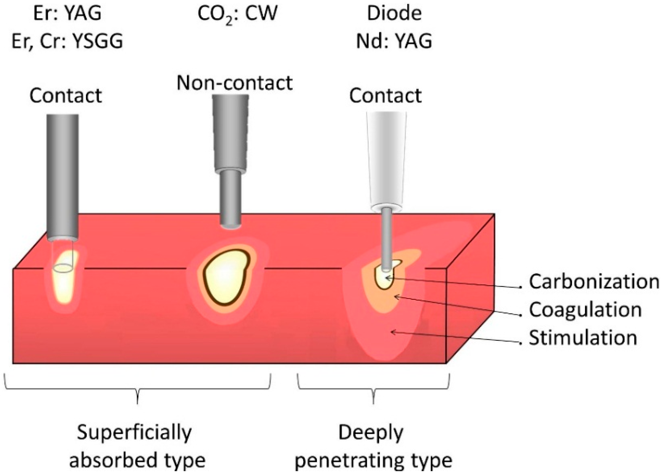
3.3.2. Dental Applications

Lasers have been used in dental applications for more than 30 years [74,76]. The first dental lasers cleared by the Food and Drug Administration (FDA) were for oral, soft-tissue procedures and included the carbon dioxide; neodymium:YAG (Nd:YAG); argon; and diode lasers. Dental laser instruments have been widely employed in soft-tissue procedures, such as gingivectomy, gingivoplasty, frenectomy, curettage, crown lengthening, for the removal of benign tumors in oral surgery, and periodontics [76,77]. The benefits of using lasers include hemostasis, precise cutting, bacterial reduction, and reduced pain. The argon laser has also has been cleared for hard-tissue use and for curing light-activated materials [77].
Lasers have numerous tissue interactions, such as ablation or vaporization of dental hard tissue [78,79,80,81], hemostasis [82], microbial inhibition and destruction, as well as biological effects, such as biostimulation (photo-bio-modulation), which induce various beneficial therapeutic effects and biological responses, like in bone regeneration in the midpalatal anterior suture [83,84]. In a similar study, it was evaluated the histologic effects of CO2 laser irradiation, during gingival surgery and the histologic effects on cortical bone following irradiation with increasing energy densities [85]. Other reports in literature relate the use of lasers for the treatment of periodontal and peri-implant infections, promoting the peri-implant healing [74,86,87,88]. Additionally, morphological changes and thermal effects of Er:YAG lasers and CO2 lasers on implants were studied, because they can be useful to remove submerged implants and to decontaminate their surfaces [89,90].
There are several reports in the literature about the effects of lasers in the dental pulp [91,92] and the first one was made by Adrian et al. [91] in 1971. The authors wanted to determine the histologic and morphologic changes that characterize the pulpal response to laser irradiation and to determine the relationship between the amount of energy deposited on the surface and the degree of pulpal response. Both the CO2 and Nd:YAG lasers have a thermal effect on both soft and hard tissues. Yet, the Er:YAG laser is more efficient in absorption, both in water and in hydroxyapatite and, for that, has been reported to have less of a thermal effect on dental hard tissue [93,94].
Over the last few years the 9.6-μm CO2 laser was developed. It has been observed that this device can preserve tissue with almost no adverse effects. In contrast, modifications of approved CO2 laser therapies of premalignant lesions resulted in higher recurrence rates than the conventional defocused laser technique. However, several studies indicate that other wavelengths such as Nd:YAG (λ = 1064 nm) or diode lasers (λ = 810 nm) may be also interesting in this field. Intraoperatively, the use of photodynamic therapy or peri-implant care of ailing implants, with the CO2 laser, seems to be more appropriate than conventional methods [95]. Er:YAG laser was also used to investigate its effect as an antibacterial agent, to disinfect root canals, and enhance bond strengths of fiber posts [96].

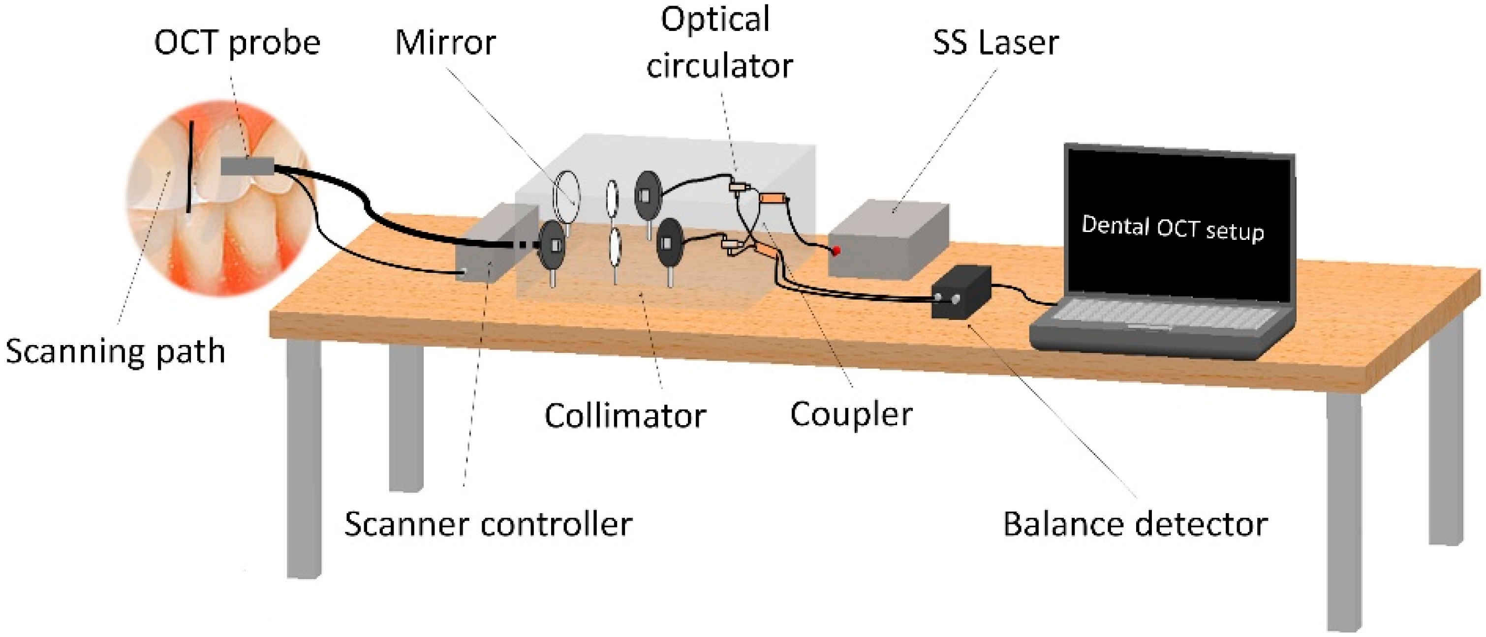
3.4. Optical Coherence Tomography (OCT)

3.4.1. Working Principles

Optical coherence tomography (OCT) is an imaging technique and has been widely used in medical applications, mainly for diagnostic purposes. Compared to other conventional imaging techniques, OCT has the advantages of being non-invasive, non-destructive and does not expose patients to radiation [97].
There are two main types of OCT: time domain OCT (TDOCT) and spectrum domain OCT (SDOCT). TDOCT can be performed by two techniques, both use two-beam interferometry: in the reflectometer technique the sample is inside the interferometer and illuminated by the sample beam only, whereas in the dual beam technique the sample is outside the interferometer and illuminated by both interferometer beams [98]. In TDOCT the path length of the reference arm is scanned in time. The interference pattern is only achieved when the optical path difference lies within the coherence length of the light source. TDOCT has been used for evaluation of indirect dental restorations, apical microleakage, monitoring the periodontal ligament changes induced by orthodontic forces, and orthodontic interfaces. In SDOCT the spectrum at the output of the low coherence interferometer is measured. The depth scan (A-scan) is calculated by a Fourier-transform from the acquired spectra, without movement of the reference arm. SDOCT has an improved signal-to-noise ratio in comparison to TDOCT, the higher the number of separate spectral windows used in the spectrometer, the larger the signal-to-noise ratio. The width of the spectral windows limits the axial scanning range, while the full spectral bandwidth sets the axial resolution. SDOCT can be also divided into swept source (SS) OCT, and camera-based, Fourier domain (FD) OCT, if it uses a narrow band or broadband optical source [99,100,101].
The OCT axial resolution is related to the light source coherence length lc, which is a function of the light source bandwidth (Δλ). The light source coherence length can be described by Equation (3) [101]:
l C = 2 c ln 2 π 1 Δ v = 2 ln 2 λ 0 2 Δ λ 0 , 44 λ 0 2 Δ λ
where λ0 is the center wavelength and Δλ is also known as the full width at half the maximum of spectrum. OCT systems, with appropriate broadband light sources, can exhibit excellent axial resolution, less than 20 μm. The transverse resolution is decided by the final spot size on the sample. Higher transverse resolution may be achieved with a focused light. The dispersion and phase compensation are also important to an OCT system.

3.4.2. Dental Applications

In dental science, OCT detects qualitative and quantitative morphological changes of dental hard and soft tissues, like for early diagnosis of dental diseases, such as caries, periodontal disease, and oral cancer, because of the excellent spatial resolution (≈15 μm) [102]. OCT can also be used in other types of applications [99,100,101], such as to evaluate the microleakage of dental restorations and endodontic fillings [103], the dental implant status [104], the integrity of dental prosthesis [105], and the surroundings of orthodontic brackets [106]. In 1991 Huang et al. [107] reported, for the first time, the development of the technique of optical coherence tomography (OCT), to measure the internal structure in biological systems and, in dentistry, a series of reports describing OCT applications appeared in 1998 [108,109,110], with imaging of both hard and soft oral tissues. In 1998 Feldchtein et al. [110] used, for the first time, OCT to perform a comprehensive program of in vivo and in vitro structural imaging of hard and soft tissues within the oral cavity. They were able to differentiate several types of healthy oral mucosa, as well as normal and abnormal tooth structure. Polarization-sensitive optical coherence tomography (PS-OCT) was used to monitor the remineralization of carious lesions, by measuring the new amount of mineral that is deposited in the outermost layers [111]. Wikaksono et al. [112] proposed the use of a combining optical imaging/sensing and mechanical function in an integrated dental drilling probe to show the feasibility of an optomechanical system for surgical optical OCT imaging and sensing in dental applications. The system was made by integrating micro lenses and optical fiber into a dental drill. Although they demonstrate the proof-of-concept of a dental drill, they did not succeed perfectly. More recently, Sun et al. [102] developed a swept-source optical coherence tomography (SS-OCT) system, using a fiber optic handheld scanning probe, for the diagnosis in real-time of crack and microleakage detection between dental composite resin and enamel. The system uses a 1310 nm swept-source laser as a broadband light source, which is separated into two arms (reference arm and sampling arm) and after that is recoupled in another optical coupler for interference. A balance detector is used for the detection of interference and a data acquisition card provided computer-photodetector interfacing. The input light, in the OCT portable probe, with 3 mm outer diameter, is focused by a collimator and then, by a proper scanning mechanism, the output light angle is changed in order to perform the scanning path (Figure 5).
Figure 5. Schematic representation of the setup of a dental handheld probe SS-OCT, for in vivo detection of crack and microleakage, between dental composite resin and enamel (adapted from [102]).
Applsci 05 01350 g005
The authors verified that SS-OCT can provide the diagnosis of in vivo tooth microleakage and it was very reliable for the diagnosis of cracks in the enamel. However, this study provided ex vivo information for large crack detection only. Further experiments must be carried out with different filling materials in order to correlate them with different image properties, such as penetration depth, image distortion, and the minimum detectable gap size.
Another trend in the application of OCT is in the study of dental materials, in the inspection of crack growth, adhesion, and shrinkage. Lin et al. [113,114] have investigated micro-crack growth and damage in the ceramic’s restorative material and in the ceramic/dentin adhesive interface, under fatigue shear testing monitored, using the acoustic emission (AE) technique combined with OCT. One of the main reasons for extensive or total failure in ceramic restorations are luting defects or resin cement wear between the ceramic restoration and the tooth substance, especially to the dentin where obtaining a reliable bond is more challenging than to the enamel because of the higher water content of dentin. In other studies it was also to analyze the marginal integrity of resin composites dental restorations and other properties by measuring the gap at the tooth–restoration interface [115,116,117].
Boadi et al. [118] also reported a study made to compare two different OCT systems: an 890 nm spectrometer-based OCT system with 2.5 µm axial resolution and a 1300 nm swept-source OCT system with 7.5 µm axial resolution, to determine the effect of these different OCT parameters on the endogenous backscatter contrast of dysplastic/malignant oral mucosa models.

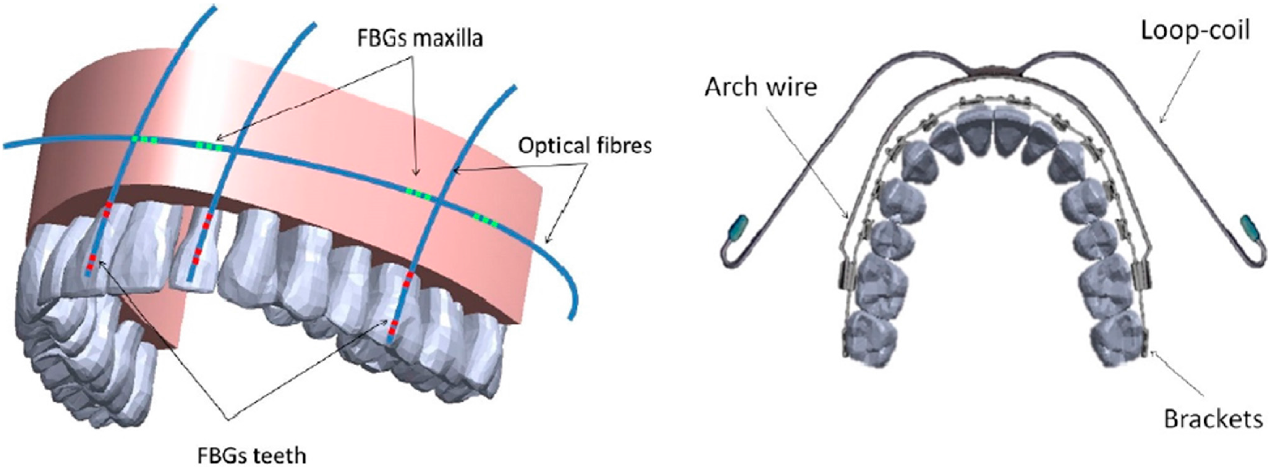
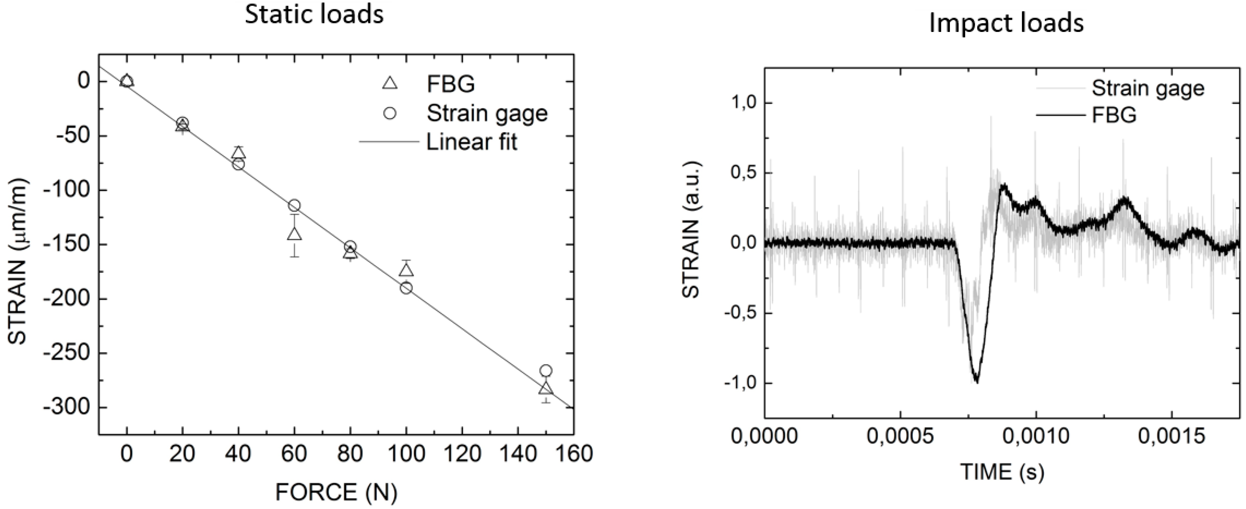
3.5. Fiber Optic Sensors (FOS)

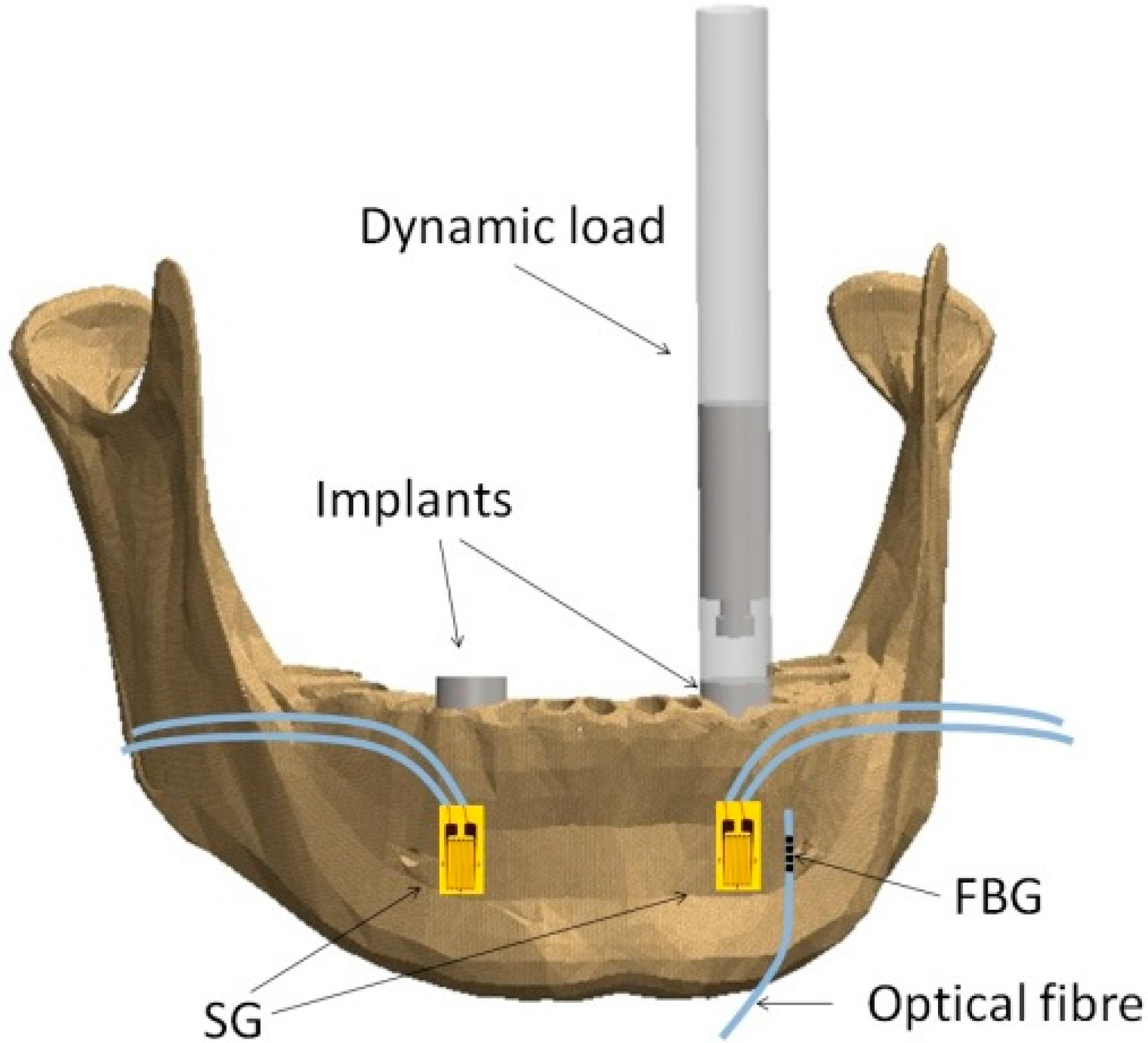
3.5.1. Working Principles

A fiber Bragg grating sensor (FBG sensor) is a periodic modulation of the refractive index of an optical fiber core. If an optical fiber that contains an FBG is illuminated by a broadband light source, only the wavelengths that satisfy the Bragg condition are reflected, all the others being transmitted. This condition is given by Equation (4):
λ B = 2 n e f f Λ
where λB is the reflected Bragg wavelength, neff the effective refractive index of the fiber core and Λ the periodicity of the refractive index modulation [18]. When the grating is subjected to thermal variations and/or mechanical perturbations the reflected Bragg wavelength changes, according with Equation (5):
Δ λ B = 2 ( Λ n e f f ε + n e f f Λ ε ) Δ ε z + 2 ( Λ n e f f T + n e f f Λ T ) Δ T
The first term represents the strain dependence on the Bragg wavelength variation and the second term, the thermal effect on the same parameter. Equation (2) shows that an FBG can be employed as a sensor element, by monitoring the back-reflected light from the Bragg grating, for longitudinal mechanical strain, εz, and temperature, T. The sensibility of an FBG to εz, is given by Equation (6):
Δ λ B λ B = { 1 n e f f 2 2 [ p 12 ν ( p 11 + p 12 ) ] } ε z
where ν is the Poisson’s ratio and pij are the components of the strain-optic tensor. For a typical germanosilicate optical fiber, the expected strain sensitivity around λB = 1550 nm is 1.2 pm/με [18].

3.5.2. Dental Applications

Prosthetics

Tjin et al. [119] was the first one using fiber optic sensors to monitor force and temperature in dental splints worn by patients suffering from sleep apnea. Dental splints are used as a clinical method to mitigate the effects of apnea, during sleep and must be used by patients during night. A way to attempt if patients are wearing it correctly and in a proper manner, during sleep, is to monitor the temperature and force exerted on the dental splint. FGB were inscribed in simple strands of optical fiber, embedded within the splint. The pressure sensor consists of an FBG embedded within three layers of glass fiber composite material (Figure 6). The glass fiber insulates the FBG from the temperature effect. Both the force and temperature sensors used in the trials were independently calibrated and were found to have accuracies of better than 0.5 N and 0.1 °C, respectively. The obtained results have suggested that monitoring of both the pressure and temperature of the dental splint as a function of time, can give a clear indication of the compliance of the patient with regard to the dental splint.
Figure 6. Schematic representation of a dental splint with embedded fiber optic sensors, to monitor force and temperature (adapted from [119]).
Applsci 05 01350 g006
Tiwari et al. [120] also have proposed a new experimental scheme, utilizing FBG sensors, to investigate and to measure the impact absorption capability of custom-made mouth guards. They used a customized pendulum device to simulate the impact loads and its response was observed using pairs of FBGs bonded to the surface of custom-made mouth guard and a typhodontic jaw model, representing normal occlusion, on similar positions.
FBG sensors were used to study the biomechanics of a mandible, in order to develop the design of temporo-mandibular joint (TMJ) implant [121]. An experimental testing device was used to apply the occlusion and muscular forces to the mandible and four FBGs were glued at the surface of a synthetic mandible. The obtained results were correlated with similar ones obtained with a numerical finite element model.

Implantology

Carvalho et al. [122] studied the load mechanism transfer in an implanted cadaveric mandible, due to static and impact loads. Uncoated FBG sensors and standard strain gages (SG) were glued directly to the surface of a human cadaveric mandible, in the direction of the longitudinal axis of the implant, to measure bone strain (Figure 7).
Figure 7. Schematic representation of an implanted cadaveric mandible with fiber Bragg grating and strain gages [122].
Applsci 05 01350 g007
For the static loads the implant was step-loaded, using an automated Shimadzu universal testing machine (UTM) up to a maximum of 160 N and the dynamic loads were generated by striking the implant with a steel mass cylinder of 52 g. The results obtained with the two types of sensors (Figure 8) showed a good agreement and FBG exhibited a higher level of signal-to-noise ratio, proving that FBG have higher sensitivity to small strains when compared to SG.
Figure 8. Comparison of results obtained with an implanted cadaveric mandible and measured with fiber Bragg grating and strain gages. Left: for static load; Right: and impact loads [122].
Applsci 05 01350 g008
FBG were also used in other studies to evaluate the performance of different types of dental implants [123,124,125]. Another topic of interest was to measure, with FBG, thermal variations in bone during implant bed preparation [126]. The atraumatic preparation of the implant bed and the presence of healthy bone factors have been considered essential for osseointegration of a dental implant. The study was performed with surgical drills with a new surface coating to evaluate the viability of a new clinical protocol without irrigation.

Orthodontics

Milczewski et al. [127] used fiber optic sensors to instrumentalize inside parts of an artificial maxilla and measure internal tension transmitted by the orthodontic and orthopedic appliances to the dentition and the adjacent bone. Bragg gratings written in a standard optical fiber were used to monitor the maxillary teeth and a multiplexed fiber was used to monitor the surface of the maxillary bone transversally to the longest axis of the teeth (Figure 9). A universal test machine was used to evaluate the sensitivity of the sensor to the vertical and lateral forces applied on the teeth.
Figure 9. Left: Schematic representation of the maxilla model instrumented with FBG sensors; Right: Occlusal image of the teeth with fixed appliance and extra-oral device (adapted from [127]).
Applsci 05 01350 g009
A wavelength shift of approximately 0.30 nm was detected when applying loads ranging from 0 to 20 N. By applying forces using the standard orthodontic appliances installed on the dentition it was possible to detect a range of forces between 0.025 N to 0.035 N during the activation of the arch wire and extra-oral forces. The use of the internal sensors in an artificial model made possible the monitoring of the resulting forces on the internal parts of the teeth and at the position where the strain takes place within the maxilla. The sensors detected that the orthodontic forces were not transmitted to the surface of the maxilla and this information is important to elucidate about undesirable effects, such as tooth root resorption and local pain, during the orthodontic treatment. In similar studies, the authors have applied other kinds of optical fiber sensors, such as crystal fibers (PCF), FBG, and Hi-Bi FBG, to the evaluate the force transmitted by orthodontic mini implants [128,129] and orthodontic appliances [130]. Other studies also had instrumented orthodontic devices and an acrylic model jaw with FBG to evaluate the differences in the strain transmitted by two orthodontic devices [131]. Similar results were also obtained in a similar study [132], where the strain patterns were not symmetric between the left and the right sides as between the posterior and anterior regions of the jaw.

Dental Materials

Shrinkage of resin-based dental materials has been measured by several methods. Common clinical problems caused by the imperfect interfacial bonding are marginal staining, bacterial micro leakage, and recurrent cavities. Optical fiber sensors have been used to monitor the setting chemical reaction of different dental materials, like dental cements, dental composite resins, dental gypsum, and fiber-reinforced composites [133,134,135,136,137]. In particular, the amount of shrinkage and the rise in temperature was studied during the setting chemical reaction of dental gypsum for different water/powder (w/p) ratios (Figure 10) [133].
Figure 10. Left: Setting expansion variations; Right: Temperature variations; during the setting chemical reaction of dental gypsum type IV, for different w/p ratios. Updated from [133], Copyright The Japanese Society for Dental Materials and Devices, 2011.
Applsci 05 01350 g010
Ottevaere et al. [135] presented, in 2000, a new method to characterize the amount of shrinkage of the cementing materials and the consecutive stresses appearing in the tooth cement-facing structure during bonding using highly birefringent single-mode optical fiber sensors and, in 2012, introduced a fully-automated setup to measure the Bragg wavelength shift of the FBG strain sensors and to accurately monitor the linear strain and shrinkage of dental resins during curing [136]. In a similar study, FBGs were used to monitor the linear strain due to the polymerization shrinkage and hydroscopic expansion, due to water sorption, of four fiber-reinforced biocomposites [137]. The polymerization shrinkage was monitored during the light curing process and the hydroscopic expansion of the samples was measured for 132 days, during which they were immersed in water. The authors have used a silicon mold to pour the samples and let them cure with blue light with embedded sensors. Three types of materials were monitored with only one sensor and the other with two sensors in orthogonal directions (Figure 11). Duplicate samples without embedded fiber sensors were made of each material in order to monitor the mass increase, due to water sorption. The strain and temperature sensitivities of the FBG sensors used within this study were 1.20 pm/με and 11 pm/°C, respectively. The strain resolution was 0.4 με and the temperature resolution was 0.05 °C.
FBG were also used to characterize the expansion of dental gypsum, for different ratios of gypsum powder and water [133]. Thermal variations were also evaluated, during the setting chemical reaction, and the linear thermal expansion coefficient was obtained. For that purpose, the authors carried out an experiment where they flowed the mixture of gypsum with water into a cylinder and used two FBG sensors. One of the sensors was in direct contact with dental gypsum, and hence sensitive to strain and temperature variations, and the other sensor was placed inside a double needle to overcome the cross sensitivity and to be only sensitive to temperature.
Figure 11. Schematic representation of the structure of the biaxial woven prepreg and the locations of the sensors, in two orthogonal directions, in the sample (adapted from [137]).
Applsci 05 01350 g011

Other Applications

In 2000 Colston et al. [138] developed a diagnostic device to permit simultaneous quantitation of multiple proteases within a single periodontal pocket, using a chemical fiber optic sensor, for the diagnosis of periodontal disease. Recent efforts were made to push forward further investigation to permit the use of FBG in in vivo studies, to perform strain measurements in bones, and that the osteoblastic biocompatibility be evaluated [139]. There is a lack of information in this topic of experimental biomechanics which is important to give further ideas on the bone remodeling process around implants, which has been so well studied by other methods. Recently, some review reports appeared in the literature, presenting the application of FOS in biomechanics, in particular dental biomechanics and in biomedical applications [140,141,142,143,144,145,146,147,148], clearly showing the great interest in this type of sensor in research.

4. Final Remarks

It is clear from the amount of literature that photonic technologies had, and still have, a huge impact in dental biomechanics, and in dentistry in general. This happens because these technologies have advantages over others and also because they are friendly for use in clinical practice. Photoelasticity was the first optical technique applied in the study of dental biomechanics and it is still in use. For that reason, it can be said that is a contemporary technique and of interest to undertake research in the area. Lasers prove to be a good choice for clinical practice because they are less time consuming, there are no radiation effects for the patients, and also less pain for them. Some further developments must be taken into account, such as the level of energy and temperature rise of the dental tissues. Additionally, OCT has demonstrated a great potential in dentistry, as in other medical areas, and it can be used not only for diagnostic purposes but also for many other dental applications. FOS have a large number of advantages compared to conventional methods in strain analysis and are suitable for a large number of biomechanical applications. However, some technical limitations in regard with the setup implementation of FOS, must be overcome in order to be user-friendly and to commercialize the technology. Finally, an overall view of the main features of the photonic techniques mentioned in the paper, are summarized in Table 1.
Table 1. Summary of main features of photonic technologies.
Photonic TechnologyAdvantagesDisadvantagesApplications
Photoelasticity [29,30,31,32,33,34,35,36,38,39,40,41,42,43,44,45]
  • full-field;
  • non-contact
  • qualitative information on stress/strain distribution;
  • uses physical replicas of the anatomical parts and dental components;
  • only applied for static loads
  • dental biomechanics research;
  • dental structure;
  • dental materials
Moiré Fringe [52,53,54]
  • full-field;
  • non-contact
  • only applied for static loads;
  • limited resolution
  • dental biomechanics research
ESPI [56,58,59,61,62,63,64,65,66,67,78,79,80,81,82,83,84,85,86,87,88,89,90,91,92,93,94,95,96,97,98]
  • full-field;
  • non-contact;
  • quantitative information on stress/strain distribution;
  • high measurement sensitivity;
  • can measure the 3D displacement
  • time consuming;
  • difficult to implement the setup
  • dental biomechanics;
  • dental structure;
  • dental materials
Lasers [78,79,80,81,82,83,84,85,86,87,88,89,90,91,92,93,94,95,96,97,98]
  • bloodless surgical field;
  • minimal swelling;
  • reduced surgical time;
  • excellent coagulation
  • can provoke damage to the skin and to the eyes;
  • greater depth of penetration into the target tissue;
  • thermal effect
  • clinical application;
  • osteotomy;
  • treatment of premalignant lesions;
  • fluorescence spectroscopy;
  • photodynamic therapy;
  • periimplant care of ailing implants;
  • hemostasis
OCT [104,105,106,107,108,109,110,111,112,113,114,115,116,117,118,119,120]
  • non-invasive;
  • non-destructive;
  • patients are not exposed to radiation;
  • high space resolution;
  • real time image
  • limited penetration depth and scanning range;
  • hard to implement the setup
  • dental soft and hard tissue morphology;
  • pre-clinical application;
  • advanced diagnosis tool for tooth decay and periodontal diseases;
  • dental materials: crack growth, adhesion; shrinkage and microleakage;
  • endodontic treatments
FOS [103,104,105,106,107,108,109,110,111,112,113,114,116,117,118,119,120,121,122,124,125,126,127,128,129,130,131,132,133,134,135,137,138,139]
  • high sensitivity;
  • compactness;
  • geometric versatility;
  • immunity to electromagnetic noise;
  • low cost;
  • can be applied for static and dynamic loads
  • limitations in setup implementation for in vivo use;
  • fragile, breakable;
  • only provide point to point data
  • dental biomechanics (orthodontics; implantology, prosthetic dentistry, endodontics);
  • materials characterization

Acknowledgments

This work was co-financed by the North Portugal Regional Operational Programme (ON.2—O Novo Norte), under the National Strategic Reference Framework (NSRF), through the European Regional Development Fund (ERDF).

Author Contributions

All the authors contributed to this work. Authors Lídia Carvalho and Orlando Frazão wrote the paper. Author Paulo Roriz made the figures. Author José Simões made the revisions.

Conflicts of Interest

The authors declare no conflict of interest.

References

  1. Lynch, C.D.; O’Sullivan, V.R.; McGillycuddy, C.T. Pierre Fauchard: The father of modern dentistry. Br. Dent. J. 2006, 201, 779–781. [Google Scholar] [CrossRef] [PubMed]
  2. Altschuler, B.R. Applications of Interferometry and Optical Metrology in Dentistry. In Applications of Optics in Medicine and Biology; Herron, R.E., Ed.; SPIE: San Diego, CA, USA, 1977. [Google Scholar]
  3. Zhou, Z.R.; Zheng, J. Tribology of dental materials: A review. J. Phys. D Appl. Phys. 2008, 41. [Google Scholar] [CrossRef]
  4. Morin, D.L.; Douglas, W.H.; Cross, M.; DeLong, R. Biophysical stress analysis of restored teeth: Experimental strain measurement. Dent. Mater. 1988, 4, 41–48. [Google Scholar] [CrossRef]
  5. Perez-Gonzalez, A.; Gonzalez-Lluch, C.; Sancho-Bru, J.L.; Cervantes, P.; Iserte-Vilar, J. Biomechanical Models of Endodontic Restorations. In Theoretical Biomechanics; Klika, V., Ed.; InTech: Vukovar, Croatia, 2011; pp. 133–160. [Google Scholar]
  6. Cerqueira, N.M.; Özcan, M.; Dent, M.; Gonçalves, M.; da Rocha, D.M.; Vasconcellos, D.K.; Bottino, M.A.; Yener-Salihoğlu, E. A strain gauge analysis of microstrain induced by various splinting methods and acrylic resin types for implant impressions. Int. J. Maxillofac. Implant. 2012, 27, 341–345. [Google Scholar]
  7. Carvalho, L.; Vaz, M.A.; Simões, J.A. Mandibular strains induced by conventional and novel dental implants. J. Strain Anal. Eng. 2004, 39, 291–297. [Google Scholar] [CrossRef]
  8. Şahin, S.; Çehreli, M.C.; Yalçin, E. The influence of functional forces on the biomechanics of implant-supported prostheses—A review. J. Dent. 2002, 30, 271–282. [Google Scholar] [CrossRef]
  9. Craig, R.G.; Peyton, F. Measurement of strains in fixed bridges with electronic strain gauges. J. Dent. Res. 1967, 46, 615–619. [Google Scholar] [CrossRef] [PubMed]
  10. He, L.H.; Swain, M.V. Enamel-A “metallic-like” deformable biocomposite. J. Dent. 2007, 35, 431–437. [Google Scholar] [CrossRef] [PubMed]
  11. Dauvillier, B.S.; Feilzer, A.J.; de Gee, A.J.; Davidson, C.L. Visco-elastic parameters of dental restorative materials during setting. J. Dent. Res. 2000, 79, 818–823. [Google Scholar] [CrossRef] [PubMed]
  12. Attar, N.; Tam, L.E.; McComb, D. Mechanical and physical properties of contemporary dental luting agents. J. Prosthet. Dent. 2003, 89, 127–134. [Google Scholar] [CrossRef] [PubMed]
  13. Braga, R.R.; Ballester, R.Y.; Ferracane, J.L. Factors involved in the development of polymerization shrinkage stress in resin-composites: A systematic review. Dent. Mater. 2005, 21, 962–970. [Google Scholar] [CrossRef] [PubMed]
  14. Chung, S.; Yap, A.; Koh, W.; Tsai, K.; Lim, C. Measurement of Poisson's ratio of dental composite restorative materials. Biomaterials 2004, 25, 2455–2460. [Google Scholar] [CrossRef] [PubMed]
  15. Goel, V.; Khera, S.C.; Ralston, J.L.; Chang, K.H. Stresses at the dentinoenamel junction of human teeth—A finite element investigation. J. Prosthet. Dent. 1991, 66, 541–549. [Google Scholar] [CrossRef]
  16. Versluis, A.; Tantbirojn, D.; Pintado, M.R.; DeLong, R.; Douglas, W.H. Residual shrinkage stress distributions in molars after composite restoration. Dent. Mater. 2004, 20, 554–564. [Google Scholar] [CrossRef] [PubMed]
  17. Magne, P. Efficient 3D finite element analysis of dental restorative procedures using micro-CT data. Dent. Mater. 2007, 23, 539–548. [Google Scholar] [CrossRef] [PubMed]
  18. Natali, A.N.; Pavan, P.G.; Ruggero, A.L. Evaluation of stress induced in peri-implant bone tissue by misfit in multi-implant prosthesis. Dent. Mater. 2006, 22, 388–395. [Google Scholar] [CrossRef] [PubMed]
  19. Geng, J.; Tan, K.; Liu, G. Application of finite element analysis in implant dentistry: A review of the literature. J. Prosthet. Dent. 2001, 85, 585–598. [Google Scholar] [CrossRef] [PubMed]
  20. El-Anwar, M.; El-Zawahry, M. A three dimensional finite element study on dental implant design. J. Gen. Eng. Biotechnol. 2011, 9, 77–82. [Google Scholar] [CrossRef]
  21. Maceri, F.; Martignoni, M.; Vairo, G. Mechanical behaviour of endodontic restorations with multiple prefabricated posts: A finite-element approach. J. Biomech. 2007, 40, 2386–2398. [Google Scholar] [CrossRef] [PubMed]
  22. Pegoretti, A.; Fambri, L.; Zappini, G.; Bianchetti, M. Finite element analysis of a glass fibre reinforced composite endodontic post. Biomaterials 2002, 23, 2667–2682. [Google Scholar] [CrossRef]
  23. Ho, M.; Lee, S.; Chen, H.; Lee, M. Three-dimensional finite element analysis of the effects of posts on stress distribution in dentin. J. Prosthet. Dent. 1994, 72, 367–372. [Google Scholar] [CrossRef]
  24. Zak, B. Photoelastic analysis in der orthodontischen mechanik. Oesterr. Z Stomatol. 1935, 35, 22–37. [Google Scholar]
  25. Noonan, M.A. The use of photoelasticity in a study of cavity preparations. J. Dent. Child 1949, 16, 24–28. [Google Scholar] [PubMed]
  26. Mahler, D.B.; Peyton, F.A. Photoelasticity as a research technique for analyzing stresses in dental structures. J. Dent. Res. 1955, 34, 831–838. [Google Scholar] [CrossRef] [PubMed]
  27. Farah, J.W.; Craig, R.G.; Sikarskie, D.L. Photoelastic and finite element stress analysis of a restored axisymmetric first molar. J. Biomech. 1973, 6, 511–520. [Google Scholar] [CrossRef]
  28. Lehman, M.L.; Meyer, M.L. Relationship of dental caries and stress: Concentrations in teeth as revealed by photoelastic tests. J. Dent. Res. 1966, 45, 1706–1714. [Google Scholar] [CrossRef] [PubMed]
  29. Assunção, W.G.; Barão, V.; Tabata, L.; Gomes, E.; Delben, J.; dos Santos, P. Biomechanics studies in dentistry: Bioengineering applied in oral implantology. J. Craniofac. Surg. 2009, 20, 1173–1177. [Google Scholar] [CrossRef] [PubMed]
  30. Craig, R.G.; El-Ebrashi, M.K.; LePeak, P.J.; Peyton, F.A. Experimental stress analysis of dental restorations: Part I. Two-dimensional photoelastic stress analysis of inlays. J. Prosthet. Dent. 1967, 17, 277–291. [Google Scholar] [CrossRef]
  31. Farah, J.W.; Craig, R.G. Reflection photoelastic stress analysis of a dental bridge. J. Dent. Res. 1971, 50, 1253–1259. [Google Scholar] [CrossRef] [PubMed]
  32. Mattison, G.D. Photoelastic stress analysis of cast-gold endodontic posts. J. Prosthet. Dent. 1982, 48, 407–411. [Google Scholar] [CrossRef]
  33. Johnson, E.; Castaldi, C.; Gau, D.; Wysocki, G. Stress pattern variations in operatively prepared human teeth, studied by three-dimensional photoelasticity. J. Dent. Res. 1968, 47, 548–558. [Google Scholar] [CrossRef] [PubMed]
  34. Standlee, J.P.; Caputo, A.A.; Hanson, E.C. Retention of endodontic dowels: Effects of cement, dowel length, diameter, and design. J. Prosthet. Dent. 1978, 39, 401–405. [Google Scholar] [CrossRef]
  35. Asundi, A.; Kishen, A. A strain gauge and photoelastic analysis of in vivo strain and in vitro stress distribution in human dental supporting structures. Arch. Oral Biol. 2000, 45, 543–550. [Google Scholar] [CrossRef]
  36. Asundi, A.; Kishen, A. Advanced digital photoelastic investigations on the tooth-bone interface. J. Biomed. Opt. 2001, 6, 224–230. [Google Scholar] [CrossRef] [PubMed]
  37. Brodsky, J.F.; Caputo, A.; Furstman, L. Root tipping: A photoelastic-histopathologic correlation. Am. J. Orthod. 1975, 67, 1–10. [Google Scholar] [CrossRef]
  38. Wang, M.; Zhang, M.; Zhang, J. Photoelastic study of the effects of occlusal surface morphology on tooth apical vertical bite forces. J. Contemp. Dent. Pract. 2004, 5, 74–93. [Google Scholar] [PubMed]
  39. Carvalho, L.; Merino, J.; Vaz, M.A.; Simões, J.A. A photoelastic analysis to assess the role of dental implant design and its relation to occlusion loads transferred to the surrounding bone. In Proceeding of the 46 eme Congrès Groupement International pour la Recherche Scientifique en Stomatologie et Odontologie, Paredes, Portugal, 25–27 April 2002; pp. 66–67.
  40. Caputo, A.A.; Standlee, J.P. Biomechanics in Clinical Dentistry; Quintessence Pub. Co.: Chicago, IL, USA, 1987. [Google Scholar]
  41. Cehreli, M.; Duyck, J.; de Cooman, M.; Puers, R.; Naert, I. Implant design and interface force transfer: A photoelastic and strain-gauge analysis. Clin. Oral Implant. Res. 2004, 15, 249–257. [Google Scholar] [CrossRef]
  42. Aguiar, F.J.; Tiossi, R.; Macedo, A.; Mattos, M.; Ribeiro, R.; Rodrigues, R. Photoelastic analysis of stresses transmitted by universal cast to long abutment on implant-supported single restorations under static occlusal loads. J. Craniofac. Surg. 2012, 23, 2019–2023. [Google Scholar] [PubMed]
  43. Ochiai, K.; Ozawa, S.; Caputo, A.; Nishimura, R. Photoelastic stress analysis of implant-tooth connected prostheses with segmented and nonsegmented abutments. J. Prosthet. Dent. 2003, 89, 495–502. [Google Scholar] [CrossRef]
  44. Celik, G.; Uludag, B. Photoelastic stress analysis of various retention mechanisms on 3-implant-retained mandibular overdentures. J. Prosthet. Dent. 2007, 97, 229–235. [Google Scholar] [CrossRef] [PubMed]
  45. Markarian, R.A.; Ueda, C.; Sendyk, C.; Laganá, D.; Souza, R. Stress distribution after installation of fixed frameworks with marginal gaps over angled and parallel implants: A photoelastic analysis. J. Prosthodont. 2007, 16, 117–122. [Google Scholar] [CrossRef] [PubMed]
  46. Kinomoto, Y.; Torii, M.; Takeshige, F.; Ebisu, S. Polymerization contraction stress of resin composite restorations in a model class I cavity configuration using photoelastic analysis. J. Esthet. Restor. Dent. 2000, 12, 309–319. [Google Scholar] [CrossRef]
  47. Asvanund, P.; Morgano, S.M. Photoelastic stress analysis of different prefabricated post-and-core materials. Dent. Mater. J. 2011, 30, 684–690. [Google Scholar] [CrossRef] [PubMed]
  48. Rezaei, A.; Soltani, F.; Vafaei, F.; Khoshhal, M.; Ayatollahi, M.R.; Soltani, N.; Nejati, M. Comparison of stresses induced by Fiber Post, Parapost and Casting Post in root canals by Photoelasticity method. Iran. Endod. J. 2010, 5, 11–16. [Google Scholar] [PubMed]
  49. Kishen, A.; Asundi, A. Photomechanical investigations on post endodontically rehabilitated teeth. J. Biomed. Opt. 2002, 7, 262–270. [Google Scholar] [CrossRef] [PubMed]
  50. Cohen, B.I.; Condos, S.; Musikant, B.L.; Deutsch, A.S. Pilot study comparing the photoelastic stress distribution for four endodontic post systems. J. Oral Rehabill. 1996, 23, 679–685. [Google Scholar] [CrossRef]
  51. Wood, J.D.; Wang, R.; Weiner, S.; Pashley, D.H. Mapping of tooth deformation caused by moisture change using moiré interferometry. Dent. Mater. 2003, 19, 159–166. [Google Scholar] [CrossRef]
  52. Wang, R.Z.; Weiner, S. Strain-structure relations in human teeth using Moiré fringes. J. Biomech. 1998, 31, 135–141. [Google Scholar] [CrossRef]
  53. Wouters, F.R.; Jon-And, C.; Abramson, N.; Olsson, L.; Frithiof, L.; Söder, P.O.; Dirtoft, I. Measurement of gingival swelling from dental casts by generation of a moiré pattern with laser light. J. Dent. Res. 1988, 67, 1118–1121. [Google Scholar] [CrossRef] [PubMed]
  54. Madjarova, V.; Kadono, H.; Toyooka, S. Dynamic electronic speckle pattern interferometry (DESPI) phase analyses with temporal Hilbert transform. Opt. Express 2003, 11, 617–623. [Google Scholar] [CrossRef] [PubMed]
  55. Yang, L.; Xie, X.; Zhu, L.; Wu, S.; Wang, Y. Review of electronic speckle pattern interferometry (ESPI) for three dimensional displacement measurement. Chin. J. Mech. Eng. 2014, 27, 1–13. [Google Scholar] [CrossRef]
  56. Jacquot, P. Speckle interferometry: A review of the principal methods in use for experimental mechanics applications. Strain 2008, 44, 57–69. [Google Scholar] [CrossRef]
  57. Lang, H.; Rampado, M.; Müllejans, R.; Raab, W.H. Determination of the dynamics of restored teeth by 3D electronic speckle pattern interferometry. Lasers Surg. Med. 2004, 34, 300–309. [Google Scholar] [CrossRef] [PubMed]
  58. Yap, A.U.; Tan, A.C.; Quan, C. Non-destructive characterization of resin-based filling materials using Electronic Speckle Pattern Interferometry. Dent. Mater. 2004, 20, 377–382. [Google Scholar] [CrossRef] [PubMed]
  59. Kachrimanis, N. The Submicron Dimensional Behavior of Post-Cure Dental Composites: An Electronic Speckle Pattern-Correlation Interferometry Study. Ph.D. Thesis, Medizinische Fakultät Charité, Universitätsmedizin Berlin, Berlin, Germany, 25 October 2013. [Google Scholar]
  60. Chattah, N.L.; Shahar, R.; Weiner, S. Design strategy of minipig molars using Electronic Speckle Pattern Interferometry: Comparison of deformation under load between the tooth-mandible complex and the isolated tooth. Adv. Mater. 2009, 21, 413–418. [Google Scholar] [CrossRef]
  61. Zaslansky, P.; Currey, J.D.; Friesem, A.A.; Weiner, S. Phase shifting speckle interferometry for determination of strain and Young᾿s modulus of mineralized biological materials: A study of tooth dentin compression in water. J. Biomed. Opt. 2005, 10. [Google Scholar] [CrossRef] [PubMed]
  62. Fages, M.; Slangen, P.; Raynal, J.; Corn, S.; Turzo, K.; Margerit, J.; Cuisinier, F.J. Comparative mechanical behavior of dentin enamel and dentin ceramic junctions assessed by speckle interferometry (SI). Dent. Mater. 2012, 28, e229–e238. [Google Scholar] [CrossRef] [PubMed]
  63. Kishen, A.; Murukeshan, V.M.; Krishnakumar, V.; Asundi, A. Analysis on the nature of thermally induced deformation in human dentine by electronic speckle pattern interferometry (ESPI). J. Dent. 2001, 29, 531–537. [Google Scholar] [CrossRef]
  64. Shahar, R.; Zaslansky, P.; Barak, M.; Friesem, A.A.; Currey, J.D.; Weiner, S. Anisotropic Poisson᾿s ratio and compression modulus of cortical bone determined by speckle interferometry. J. Biomech. 2007, 40, 252–264. [Google Scholar] [CrossRef] [PubMed]
  65. Botto, A.P.; Carvalho, L.; Monteiro, J.; Ramos, N.V.; Vaz, M.; Hecke, M.B.; Ustrell, J. Evaluation of the displacements transmitted to a pig jaw, by orthodontic and orthopaedic devices. In Proceeding of the International Conference on BIODENTAL Engineering, Porto, Portugal, 26–27 June 2009.
  66. Chuang, S.F.; Chen, T.Y.; Chang, C.H. Application of digital image correlation method to study dental composite shrinkage. Strain 2008, 44, 231–238. [Google Scholar] [CrossRef]
  67. Li, J.; Fok, A.S.L.; Satterthwaite, J.; Watts, D.C. Measurement of the full-field polymerization shrinkage and depth of cure of dental composites using digital image correlation. Dent. Mater. 2009, 25, 582–588. [Google Scholar] [CrossRef] [PubMed]
  68. Chuang, S.F.; Chang, C.H.; Chen, T.Y. Spatially resolved assessments of composite shrinkage in MOD restorations using a digital-image-correlation technique. Dent. Mater. 2011, 27, 134–143. [Google Scholar] [CrossRef] [PubMed]
  69. Li, J.; Lau, A.; Fok, A.S.L. Application of digital image correlation to full-field measurement of shrinkage strain of dental composites. Appl. Phys. Eng. 2013, 14, 1–10. [Google Scholar] [CrossRef]
  70. Lau, A.; Li, J.; Heo, Y.C.; Fok, A. A study of polymerization shrinkage kinetics using digital image correlation. Dent. Mater. 2015, 31, 391–398. [Google Scholar] [CrossRef] [PubMed]
  71. Tiossi, R.; de Torres, E.; Rodrigues, R.; Conrad, H.; de Mattos, M.G.; Fok, A.S.; Ribeiro, R.F. Comparison of the correlation of photoelasticity and digital imaging to characterize the load transfer of implant-supported restorations. J. Prosthet. Dent. 2014, 112, 276–284. [Google Scholar] [CrossRef] [PubMed]
  72. Karl, M.; Dickinson, A.; Holst, S.; Holst, A. Biomechanical methods applied in dentistry: A comparative overview of photoelastic examinations, strain gauge measurements, finite element analysis and three-dimensional deformation analysis. Eur. J. Prosthodont. Restor. Dent. 2009, 17, 50–57. [Google Scholar] [PubMed]
  73. Downs, J.C.; Convissar, R.; Anagnostaki, E.; Sun, G.; Hoopingarner, C.R. Lasers in Fixed Prosthetic and Cosmetic Reconstruction. In Principles and Practice of Laser Dentistry, 2nd ed.; Convissar, R.A., Ed.; Elsevier Inc.: New York, NY, USA, 2016; pp. 89–106. [Google Scholar]
  74. Aoki, A.; Mizutani, K.; Schwarz, F.; Sculean, A.; Yukna, R.A.; Takasaki, A.A.; Romanos, G.E.; Taniguchi, Y.; Sasaki, K.M.; Zeredo, J.L.; et al. Periodontal and peri-implant wound healing following laser therapy. J. Periodontol. 2015, 68, 217–269. [Google Scholar] [CrossRef] [PubMed]
  75. Walsh, L.J. The current status of laser applications in dentistry. Aust. Dent. J. 2003, 48, 146–155. [Google Scholar] [CrossRef] [PubMed]
  76. Dederich, D.N.; Bushick, R.D. Lasers in dentistry. J. Am. Dent. Assoc. 2004, 135, 204–212. [Google Scholar] [CrossRef] [PubMed]
  77. Cozean, C.; Arcoria, C.; Pelagalli, J.; Powell, G.L. Dentistry for the 21st century? Erbium:YAG laser for teeth. J. Am. Dent. Assoc. 1997, 128, 1080–1087. [Google Scholar] [CrossRef] [PubMed]
  78. Seka, W.D.; Featherstone, J.D.B.; Fried, D.; Visuri, S.R.; Walsh, J.T. Laser ablation of dental hard tissue: From explosive ablation to plasma-mediated ablation. In Proceeding of the SPIE 2672, Lasers in Dentistry II, 144, San Jose, CA, USA, 27 January 1996.
  79. Fried, D.; Zuerlein, M.; Featherstone, J.D.B.; Seka, W.; Duhn, C.; McCormack, S.M. IR laser ablation of dental enamel: Mechanistic dependence on the primary absorber. Appl. Surf. Sci. 1998, 127–129, 852–856. [Google Scholar] [CrossRef]
  80. Perhavec, T.; Gorkič, A.; Bračun, D.; Diaci, J. A method for rapid measurement of laser ablation rate of hard dental tissue. Opt. Laser Technol. 2009, 41, 397–402. [Google Scholar] [CrossRef]
  81. Featherstone, J.D.; Nelson, D.G. Laser effects on dental hard tissues. Adv. Dent. Res. 1987, 1, 21–26. [Google Scholar] [PubMed]
  82. Rao, G.; Tripthi, P.S.; Srinivasan, K. Hemostatic effect of the CO2 laser over excision of an intraoral hemangioma. Int. J. Laser Dent. 2012, 2, 74–77. [Google Scholar] [CrossRef]
  83. Angeletti, P.; Pereira, M.D.; Gomes, H.C.; Hino, C.T.; Ferreira, L.M. Effect of low-level laser therapy (GaAlAs) on bone regeneration in midpalatal anterior suture after surgically assisted rapid maxillary expansion. Oral Surg. Oral Med. Oral Pathol. Oral Radiol. Endod. 2010, 109, e38–e46. [Google Scholar] [CrossRef] [PubMed]
  84. Saito, S.; Shimizu, N. Stimulatory effects of low-power laser irradiation on bone regeneration in midpalatal suture during expansion in the rat. Am. J. Orthod. Dentofac. Orthop. 1997, 111, 525–532. [Google Scholar] [CrossRef]
  85. Krause, L.S.; Cobb, C.M.; Rapley, J.W.; Killoy, W.J.; Spencer, P. Laser irradiation of bone. I. An in vitro study concerning the effects of the CO2 laser on oral mucosa and subjacent bone. J. Periodontol. 1997, 68, 872–880. [Google Scholar] [CrossRef] [PubMed]
  86. Ishikawa, I.; Aoki, A.; Takasaki, A.A. Potential applications of Erbium:YAG laser in periodontics. J. Periodontal Res. 2004, 39, 275–285. [Google Scholar] [CrossRef] [PubMed]
  87. Ishikawa, I.; Aoki, A.; Takasaki, A.A. Clinical application of Erbium:YAG laser in periodontology. J. Int. Acad. Periodontol. 2008, 10, 22–30. [Google Scholar] [PubMed]
  88. Sculean, A.; Schwarz, F.; Becker, J. Anti-infective therapy with an Er:YAG laser: Influence on peri-implant healing. Expert Rev. Med. Devices 2005, 2, 267–276. [Google Scholar] [CrossRef] [PubMed]
  89. Matsuyama, T.; Aoki, A.; Oda, S.; Yoneyama, T.; Ishikawa, I. Effects of the Er:YAG laser irradiation on titanium implant materials and contaminated implant abutment surfaces. J. Clin. Laser Med. Surg. 2003, 21, 7–17. [Google Scholar] [CrossRef] [PubMed]
  90. Oyster, D.K.; Parker, W.B.; Gher, M.E. CO2 lasers and temperature changes of titanium implants. J. Periodontol. 1995, 66, 1017–1024. [Google Scholar] [CrossRef] [PubMed]
  91. Adrian, J.C.; Bernier, J.L.; Sprague, W.G. Laser and the dental pulp. J. Am. Dent. Assoc. 1971, 83, 113–117. [Google Scholar] [CrossRef] [PubMed]
  92. Sonntag, K.D.; Klitzman, B.; Burkes, E.J.; Hoke, J.; Moshonov, J. Pulpal response to cavity preparation with the Er:YAG and Mark III free electron lasers. Oral Surg. Oral Med. Oral Pathol. Oral Radiol. Endod. 1996, 81, 695–702. [Google Scholar] [CrossRef]
  93. Wigdor, H.; Abt, E.; Ashrafi, S.; Walsh, J.T. The effect of lasers on dental hard tissues. J. Am. Dent. Assoc. 1993, 124, 65–70. [Google Scholar] [CrossRef] [PubMed]
  94. Walsh, L.J. The current status of low level laser therapy in dentistry. Part 2. Hard tissue applications. Aust. Den. J. 1997, 42, 302–306. [Google Scholar] [CrossRef]
  95. Deppe, H.; Horch, H.-H. Laser applications in oral surgery and implant dentistry. Lasers Med. Sci. 2007, 22, 217–221. [Google Scholar] [CrossRef] [PubMed]
  96. Bitter, K.; Noetzel, J.; Volk, C.; Neumann, K.; Kielbassa, A. Bond strength of fiber posts after the application of Erbium:Yttrium-Aluminum-Garnet Laser treatment and gaseous ozone to the root canal. J. Endodont. 2008, 34, 306–309. [Google Scholar] [CrossRef] [PubMed]
  97. Baumgartner, A.; Dichtl, S.; Hitzenberger, C.K.; Sattmann, H.; Robl, B.; Moritz, A.; Fercher, A.F.; Sperr, W. Polarization-sensitive optical coherence tomography of dental structures. Caries Res. 2000, 34, 59–69. [Google Scholar] [CrossRef] [PubMed]
  98. Fercher, A.F.; Drexler, W.; Hitzenberger, C.K.; Lasser, T. Optical coherence tomography—Principles and applications. Rep. Prog. Phys. 2003, 66. [Google Scholar] [CrossRef]
  99. Canjau, S.; Todea, C.; Negrutiu, M.L.; Sinescu, C.; Topala, F.I.; Marcauteanu, C.; Manescu, A.; Duma, V.-F.; Bradu, A.; Podoleanu, A.G. Optical coherence tomography for non-invasive ex vivo investigations in dental medicine—A joint group experience (Review). СТМ 2015, 7, 97–115. [Google Scholar] [CrossRef]
  100. Todea, C.; Negrutiu, M.L.; Balabuc, C.; Sinescu, C.; Topala, F.I.; Marcauteanu, C.; Canjau, S.; Semez, G.; Podoleanu, A.G. Optical coherence tomography applications in dentistry. TMJ 2010, 60, 5–17. [Google Scholar]
  101. Hsieh, Y.; Ho, Y.; Lee, S.; Chuang, C.; Tsai, J.; Lin, K.; Sun, C.-W. Dental optical coherence tomography. Sensors 2013, 13, 8928–8949. [Google Scholar] [CrossRef] [PubMed]
  102. Sun, C.; Ho, Y.; Lee, S. Sensing of tooth microleakage based on dental optical coherence tomography. J. Sens. 2015, 2015. [Google Scholar] [CrossRef]
  103. Todea, C.; Balabuc, C.; Sinescu, C.; Filip, L.; Kerezsi, C.; Calniceanu, M.; Negrutiu, M.; Bradu, A.; Hughes, M.; Podoleanu, A.G. En face optical coherence tomography investigation of apical microleakage after laser-assisted endodontic treatment. Lasers Med. Sci. 2010, 25, 629–639. [Google Scholar] [CrossRef] [PubMed]
  104. Sinescu, C.; Hughes, M.; Bradu, A.; Negrutiu, M.; Todea, C.; Antonie, S.; Laissue, P.; Rominu, M.; Podoleanu, A. Implant bone interface investigated with a non-invasive method: Optical coherence tomography. In Proceedings of Biophotonics: Photonic Solutions for Better Health Care Jürgen Popp, Strasbourg, France, 7 April 2008.
  105. Sinescu, C.; Negrutiu, M.L.; Todea, C.; Balabuc, C.; Filip, L.; Rominu, R.; Bradu, A.; Hughes, M.; Podoleanu, A.G. Quality assessment of dental treatments using en-face optical coherence tomography. J. Biomed. Opt. 2008, 13. [Google Scholar] [CrossRef] [PubMed]
  106. Fried, D.; Staninec, M.; Darling, C.; Kang, H.; Chan, K. Monitoring tooth demineralization using a cross polarization optical coherence tomographic system with an integrated MEMS scanner. Proc. SPIE Int. Soc. Opt. Eng. 2012. [Google Scholar] [CrossRef]
  107. Huang, D.; Swanson, E.A.; Lin, C.P.; Schuman, J.S.; Stinson, W.G.; Chang, W.; Hee, M.R.; Flotte, T.; Gregory, K.; Puliafito, C.A.; et al. Optical coherence tomography. Science 1991, 254, 1178–1181. [Google Scholar] [CrossRef] [PubMed]
  108. Everett, M.; Colston, B.W.; da Silva, L.B.; Otis, L.L. Fiber Optic Based Optical Coherence Tomography (OCT) for Dental Applications; Fourth Pacific Not thwest Fiber Optic Sensor Workshop: Portland, OR, USA, 1998. [Google Scholar]
  109. Colston, B.; Everett, M.; da Silva, L.; Otis, L.L.; Stroeve, P.; Nathel, H. Imaging of hard- and soft-tissue structure in the oral cavity by optical coherence tomography. Appl. Opt. 1998, 37, 3582–3585. [Google Scholar] [CrossRef] [PubMed]
  110. Feldchtein, F.; Gelikonov, V.; Iksanov, R.; Gelikonov, G.; Kuranov, R.; Sergeev, A.; Gladkova, N.; Ourutina, M.; Reitze, D.; Warren, J. In vivo OCT imaging of hard and soft tissue of the oral cavity. Opt. Express 1998, 3, 239–250. [Google Scholar] [CrossRef] [PubMed]
  111. Kang, H.; Darling, C.; Fried, D. Nondestructive monitoring of the repair of enamel artificial lesions by an acidic remineralization model using polarization-sensitive optical coherence tomography. Dent. Mater. 2012, 28, 488–494. [Google Scholar] [CrossRef] [PubMed]
  112. Wicaksono, D.H.B.; Margallo-Balbás, E.; French, P.J.; Pandraud, G.; Breedveld, P.; Dankelman, J. Micro-optics assembly in dental drill as a platform for imaging and sensing during surgical drilling. In Proceedings of the IEEE Sensors, Kona, HI, USA, 1–4 November 2010; pp. 265–268.
  113. Lin, C.L.; Kuo, W.C.; Chang, Y.H.; Yu, J.J.; Lin, Y.C. Examination of ceramic/enamel interfacial debonding using acoustic emission and optical coherence tomography. Dent. Mater. 2014, 30, 910–916. [Google Scholar] [CrossRef] [PubMed]
  114. Lin, C.L.; Kuo, W.C.; Yu, J.J.; Huang, S.F. Examination of ceramic restorative material interfacial debonding using acoustic emission and optical coherence tomography. Dent. Mater. 2013, 29, 382–388. [Google Scholar] [CrossRef] [PubMed]
  115. Monteiro, G.; Montes, M.; Gomes, A.; Mota, C.; Campello, S.; Freitas, A. Marginal analysis of resin composite restorative systems using optical coherence tomography. Dent. Mater. 2011, 27, e213–e223. [Google Scholar] [CrossRef] [PubMed]
  116. De Melo, L.S.A.; de Araujo, R.E.; Freitas, A.Z.; Zezell, D.; Vieira, J.N.D.; Girkin, J.; Hall, A.; Carvalho, M.T.; Gomes, A.S. Evaluation of enamel dental restoration interface by optical coherence tomography. J. Biomed. Opt. 2005, 10. [Google Scholar] [CrossRef] [PubMed]
  117. Tomlins, P.; Palin, W.; Shortall, A.; Wang, R. Time-resolved simultaneous measurement of group index and physical thickness during photopolymerization of resin-based dental composite. J. Biomed. Opt. 2013, 12. [Google Scholar] [CrossRef] [PubMed]
  118. Boadi, J.; Fernandes, J.; Mittar, S.; Hearnden, V.; Lu, Z.; MacNeil, S.; Thornhill, M.H.; Murdoch, C.; Hunter, K.D.; Matcher, S.J. Imaging of 3D tissue-engineered models of oral cancer using 890 and 1300 nm optical coherence tomography. CTM 2015, 7, 60–68. [Google Scholar] [CrossRef]
  119. Tjin, S.C.; Tan, Y.K.; Yow, M.; Lam, Y.Z.; Hao, J. Recording compliance of dental splint use in obstructive sleep apnoea patients by force and temperature modelling. Med. Biol. Eng. Comput. 2001, 39, 182–184. [Google Scholar] [CrossRef] [PubMed]
  120. Tiwari, U.; Mishra, V.; Bhalla, A.; Singh, N.; Jain, S.C.; Garg, H.; Raviprakash, S.; Grewal, N.; Kapur, P. Fiber Bragg grating sensor for measurement of impact absorption capability of mouthguards. Dent. Traumatol. 2011, 27, 263–268. [Google Scholar] [CrossRef] [PubMed]
  121. Silva, J.C.C.; Ramos, A.; Carvalho, L.; Nogueira, R.N.; Ballu, A.; Mesnard, M. Fibre Bragg grating sensing and finite element analysis of the biomechanics of the mandible. In Proceeding of the 17th International Conference in Optical Fibre Sensors, Bruges, Belgium, 30 August 2005; pp. 102–105.
  122. Carvalho, L.; Silva, J.C.C.; Nogueira, R.N.; Pinto, J.L.; Kalinowski, H.J.; Simões, J.A. Application of Bragg grating sensors in dental biomechanics. J. Strain Anal. Eng. 2006, 41, 411–416. [Google Scholar] [CrossRef]
  123. Carvalho, P.; Abe, L.; Schiller, M.W.; Carvalho, L.; Simões, J.A. FEA and Experimental FBG Sensing System for the Analysis of Different Dental Implant Concepts. In Proceeding of the 5th World Congress of Biomechanics, Munich, Germany, 29 July–4 August 2006; p. S568.
  124. Schiller, M.W.; Abe, I.; Carvalho, P.; Lopes, P.; Carvalho, L.; Nogueira, R.N. On the Use of FBG Sensors to Assess the Performance of a Dental Implant System. In Proceeding of the Optical Fiber Sensors, Cancun, Mexico, 23–26 October 2006.
  125. Silva, J.; Carvalho, L.; Nogueira, R.; Simões, J.; Pinto, J.; Kalinowski, H. FBG applied in dynamic analysis of an implanted cadaveric mandible. In Proceeding of the Second European Workshop on Optical Fibre Sensors, Santander, Spain, 9–11 June 2004; pp. 226–229.
  126. Fangaia, S.; Almeida, M.; Carvalho, L.; Nicolau, P. In Vitro Pilot Study on Bone Heating During Surgical Implant Bed Preparation. In Biodental Engineering II; Taylor & Francis Group, Ed.; CRC Press: London, UK, 2013; pp. 93–96. [Google Scholar]
  127. Milczewski, M.S.; da Silva, J.C.C.; Martelli, C.; Grabarski, L.; Abe, I.; Kalinowski, H.J. Force monitoring in a maxilla model and dentition using optical fiber bragg gratings. Sensors 2012, 12, 11957–11965. [Google Scholar] [CrossRef] [PubMed]
  128. Milczewski, M.S.; Martelli, C.; Canning, J.; Kalinowski, H.J.; Simões, J.A.; Stevenson, M.; Talaia, P. Orthodontic forces sensing with polymer PCF. In Proceeding of the Third European Workshop on Optical Fibre Sensors, 66191M, Napoly, Italy, 4 July 2007.
  129. Trannin, P.; Milczewski, M.; de Oliveira, W.; Filho, O.G.; Lopes, S.; Kalinowski, H. Orthodontic mechanics using mini-implant measured by FBG. In Proceeding of the Fifth Asia-Pacific Optical Sensors Conference, Jeju, Korea, 20 July 2015; pp. 96551N–96551N-4.
  130. Milczeswki, M.S.; Silva, J.C.C.; Abe, I.; Simões, J.A.; Paterno, A.S.; Kalinowski, H.J. Measuring Orthodontic Forces with HiBi FBG Sensors. In Proceding of the Optical Fiber Sensors, Cancun, Mexico, 23 October 2006.
  131. Carvalho, L.; Roriz, P.; Frazão, O.; Marques, M.B. Evaluation of the performance of orthodontic devices using FBG sensors. J. Phys.: Conf. Ser. 2015, 605. [Google Scholar] [CrossRef]
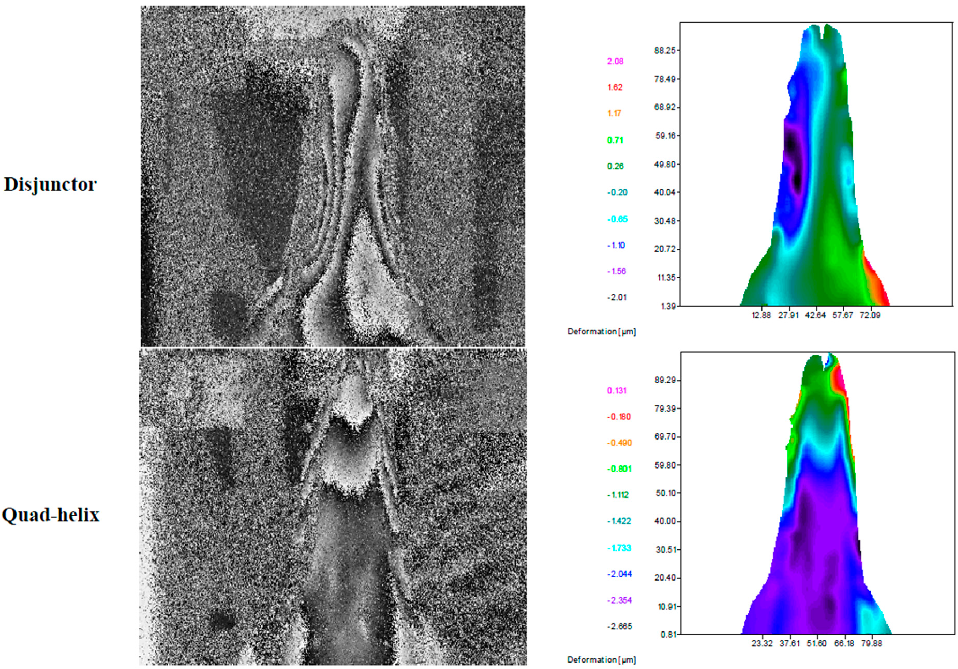
  132. Botto, A.P.; Carvalho, L.; Ustrell, J.; Pinto, J.L. Evaluation and comparison of strains transmitted to a pig jaw with fiber Bragg grating sensors, by the orthodontic devices Quad-Helix and Disjunctor. In Proceeding of the 54ème Congrès Annuel du GIRSO, La Grande Motte, France, 22–24 April 2010.
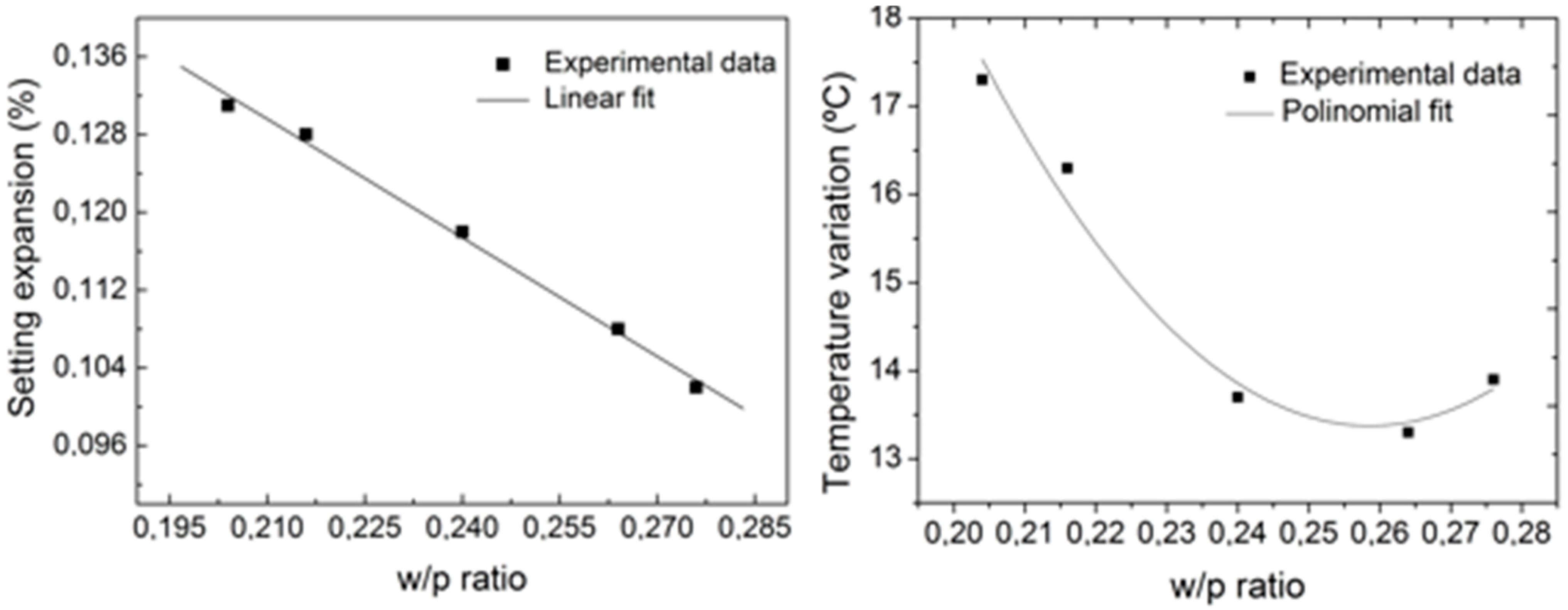
  133. Alberto, N.; Carvalho, L.; Lima, H.; Antunes, P.; Nogueira, R.; Pinto, J.L. Characterization of different water/powder ratios of dental gypsum using fiber Bragg grating sensors. Dent. Mater. J. 2011, 30, 700–706. [Google Scholar] [CrossRef] [PubMed]
  134. Milczewski, M.S.; da Silva, J.C.C.; Abe, I.; Carvalho, L.; Nogueira, R.N.; Paterno, A.S.; Kalinowski, H.J.; Pinto, J.L. Determination of setting expansion of dental materials using fibre optical sensing. Meas. Sci. Technol. 2006, 17, 1152–1156. [Google Scholar] [CrossRef]
  135. Ottevaere, H.; Tabak, M.; Bartholomees, F.; de Wilde, W.P. A novel optical characterization technique for monitoring the stress build-up in dental cements. In Proceeding of Symposium IEEE/LEOS Benelux Chapter, 2000, Delft, The Netherlands, 15 July 2014; pp. 83–86.
  136. Ottevaere, H.; Tabak, M.; Chah, K.; Mégret, P.; Thienpont, H. Dental composite resins: Measuring the polymerization shrinkage using optical fiber Bragg grating sensors. In Proceeding of the SPIE 8439, Optical Sensing and Detection II, Brussels, Belgium, 16 April 2012.
  137. Anttila, E.J.; Krintilä, O.H.; Laurila, T.K.; Lassila, L.V.J.; Vallittu, P.K.; Hernberg, R.G.R. Evaluation of polymerization shrinkage and hydroscopic expansion of fiber-reinforced biocomposites using optical fiber Bragg grating sensors. Dent. Mater. 2008, 24, 1720–1727. [Google Scholar] [CrossRef] [PubMed]
  138. Colston, B.W.; Gutierrez, D.M.; Everett, M.J.; Brown, S.B.; Langry, K.C.; Cox, R.; Johnson, P. W.; Roe, J.N. Intraoral Fiber-Optic-Based Diagnostic for Periodontal Disease. In Proceeding of International Symposium on Biomedical Optics, San Jose, CA, USA, 21–25 February 2000.
  139. Carvalho, L.; Alberto, N.; Gomes, P.; Nogueira, R.; Pinto, J.L.; Fernandes, M.H. In the trail of a new bio-sensor for measuring strain in bone: Osteoblastic biocompatibility. Biosens. Bioelectron. 2011, 26, 4046–4052. [Google Scholar] [CrossRef] [PubMed]
  140. Al-Fakih, E.; Osman, N.; Adikan, F. The use of fiber bragg grating sensors in biomechanics and rehabilitation applications: The state-of-the-art and ongoing research topics. Sensors 2012, 12, 12890–12926. [Google Scholar] [CrossRef] [PubMed]
  141. Roriz, P.; Carvalho, L.; Frazão, O.; Santos, J.L.; Simões, J.A. From conventional sensors to fibre optic sensors for strain and force measurements in biomechanics applications: A review. J. Biomech. 2014, 47, 1251–1261. [Google Scholar] [CrossRef] [PubMed]
  142. Mishra, V.; Singh, N.; Tiwari, U.; Kapur, P. Fiber grating sensors in medicine: Current and emerging applications. Sens. Actuator A: Phys. 2011, 167, 279–290. [Google Scholar] [CrossRef]
  143. Peterson, J.I.; Vurek, G.G. Fiber-optic sensors for biomedical applications. Science 1984, 224, 123–127. [Google Scholar] [CrossRef] [PubMed]
  144. Roriz, P.; Frazao, O.; Lobo-Ribeiro, A.B.; Santos, J.L.; Simoes, J.A. Review of fiber-optic pressure sensors for biomedical and biomechanical applications. J. Biomed. Opt. 2013, 18. [Google Scholar] [CrossRef] [PubMed]
  145. Roriz, P.; Ramos, A.; Santos, J.L.; Simões, J.A. Fiber optic intensity-modulated sensors: A review in biomechanics. Photonic Sens. 2012, 2, 315–330. [Google Scholar] [CrossRef]
  146. Zawawi, M.A.; O᾿Keffe, S.; Lewis, E. Intensity-modulated fiber optic sensor for health monitoring applications: A comparative review. Sens. Rev. 2013, 33, 57–67. [Google Scholar] [CrossRef]
  147. Elsarnagawy, T.; El-Wakad, M. Investigating the prospective use of fibre-optics-based sensors in dentistry. Technisch. Mess. Tech. Mess. 2008, 75, 207–211. [Google Scholar]
  148. Keiser, G.; Xiong, F.; Cui, Y.; Shum, P.P. Review of diverse optical fibers used in biomedical research and clinical practice. J. Biomed. Opt. 2014, 19. [Google Scholar] [CrossRef] [PubMed]

