Article

Effect of the Impact of Chemical and Environmental Factors on the Durability of the High Density Polyethylene (HDPE) Geogrid in a Sanitary Landfill

by
Agnieszka Kiersnowska
1,*,
Eugeniusz Koda
1,
Wojciech Fabianowski
2 and
Jacek Kawalec
3
1
Department of Geotechnical Engineering, Faculty of Civil and Environmental Engineering, Warsaw University of Life Sciences, 02-787 Warsaw, Poland
2
Faculty of Chemistry, Warsaw University of Technology, Noakowskiego 3, 00-664 Warsaw, Poland
3
Faculty of Civil Engineering, Silesian University of Technology, Akademicka 5, 44-100 Gliwice, Poland
*
Author to whom correspondence should be addressed.
Appl. Sci. 2017, 7(1), 22; https://doi.org/10.3390/app7010022
Submission received: 12 October 2016 / Revised: 6 December 2016 / Accepted: 15 December 2016 / Published: 23 December 2016
(This article belongs to the Section Materials Science and Engineering)

Abstract

:
A high density polyethylene (HDPE) uniaxial geogrid was exhumed after twenty years of service in a sanitary landfill, and its properties were examined. A geogrid installed in a landfill is exposed to mechanical and chemical factors (e.g., a wide pH range and high temperatures), as well as different weather conditions. This paper presents the results of physical and mechanical analyses of virgin and aged HDPE geogrid samples. Structural changes observed by differential scanning calorimetry and Fourier transform infrared spectroscopy (FT-IR) spectroscopy correlate with the mechanical properties of the aged geogrid. The mechanical properties were found to have changed only slightly. In the FT-IR spectrum of the topmost layer of the aged geogrid samples, no significant changes were observed compared to the spectrum of the top layer of the virgin samples. This indicates the strong chemical resistance of the HDPE material, which is able to withstand environmental conditions for at least 20 years of service in a landfill.

1. Introduction

Geogrids are widely used as reinforcements in slopes, walls, roads, and foundations where they are subjected to constant stress throughout their service life [1,2,3]. Uniaxial high density polyethylene (HDPE) geogrids are designed to be used in geotechnical structures where soil particles need support over long time periods.
HDPE geogrids, due to their high strength and durability, are commonly used for the construction of steep slopes, where the rigid nodes of the geogrids are used to wedge soil in the mesh of the geogrids. Grain aggregates or soil particles pass through the geogrid mesh, partly clogging the spaces between the ribs. The strength and stiffness of the ribs prevent the displacement of soils on the sides but may lead to mechanical damage of the material [3,4,5]. The grid interaction with soil is a complex phenomenon and depends on several factors, such as soil type and density, grid geometry and mechanical properties, surface roughness, stress levels, and boundary and loading conditions.
Geogrids embedded in soil both during the construction phase and during service life, used as reinforcements, can be exposed to different load conditions. The applied tensile loads on the geosynthetics can be permanent loads (dead weight of soil), repetitive loads (traffic loads), and loads applied during construction [6].
Viscosity is recognized as a significant property of polymeric materials. The loading rate effects, creep deformation, and stress relaxation of polymeric geosynthetics are inherent responses to their viscous properties. The viscous properties of polymeric geosynthetics have been investigated by tensile tests with respect to the loading rate, where the deformation characteristics of polymeric geosynthetic reinforcements are more or less viscous, and the peak strength decreases noticeably with a decrease in the strain rate at failure [7,8].
These features have been studied by various experimental and theoretical methods [6,7,8,9,10,11,12]. However, these materials are exposed not only to mechanical effects but also to influences of the environment in which they are used, as well as the ageing process. Current standards claim up to 120 years of design life for the structures; therefore, geogrids as components of such structures must also fulfil this age criterion [13,14,15]. The properties of geosynthetic material, including geogrids, generally depend on time.
The decrease in the allowable tensile strength depends on short-term effects, such as installation damage, which reduces the maximum tensile strength but does not further affect long-term properties, as well as on effects such as creep and ageing by oxidation and abrasion, which result in a loss in long-term strength [16]. The service life of a structure with geosynthetic material largely depends on its durability over time.
The ageing process of geosynthetic materials can be envisioned as the simultaneous combination of physical and chemical ageing [17,18,19,20]. As a result of ageing or degradation, several detrimental effects occur in the polymer: loss of additives and plasticizers, change in molecular weight, formation of free radicals and brittleness [21].
Physical ageing is related to degradation, which does not involve modifications in the molecular structure of the polymer chains. Some of these mechanisms involve mass transfer with the environment surrounding the material (extraction of additive, absorption of solvent, etc.). Others involve modifications of the organization of the internal chain in the material, i.e., change in morphology (chain orientation, crystallinity, etc.) [22]. In physical aging, the material attempts to establish an equilibrium from its as-manufactured non-equilibrium state. As a consequence, no primary (covalent) bonds are broken, and for semi-crystalline polymers such as HDPE, an increase in the material crystallinity occurs [19,23].
The mechanism of chemical ageing leads to changes in the molecular structure of the polymer chains [14]. This process eventually results in a decline in the mechanical properties and consequently damage to the material. Chemical attack can be launched directly in acidic and alkaline soils or indirectly by active waste, which is present in landfills. Depending on the chemical compound, a change in the structure of the polymer can be obtained by oxidation, chain scission, cross-linking, swelling or dissolution of the polymers. Furthermore, the effect of chemical degradation can be accelerated by temperature [24].
The predominant mechanism of degradation for most polymeric materials (geosynthetics) is chain cutting that occurs as a result of reactions of the polymer, which leads to the breakage of bonds in the backbone of the polymer chain, reduction in the chain length, and thus reduction in the molecular weight [25]. This phenomenon significantly alters the properties of polymeric materials, such as strength and elongation, and consequently affects the geotechnical structures. The oxidation process is initiated by heat (from temperature or UV (ultraviolet) radiation), mechanical stress, catalyst residues derived from the production of the geosynthetics, or reaction with impurities [26].
High density polyethylene (HDPE) geogrids are very resistant to chemical substances and do not easily deteriorate when exposed to alkaline and acid agents (except oxidizing acids), salt solutions, or microbes, because they are non-polar in nature [22]. However, in general there is more than one degradation mechanism operating at a given time, and synergistic effects (changes in pH, changes in temperature and changes in mechanical stress) can accelerate degradation [21].
Geosynthetics made from high density polyethylene have a potential for stress cracking, which is material failure caused by tensile stresses lower than the short-term mechanical strength. Cracking is usually formed in areas or regions with concentrated stress in the microstructure of local inhomogeneities. This phenomenon consists of two phases: crack initiation and crack growth. Environmental stress cracking (ESC) is the bursting of the polymer under tension when exposed to a chemical environment [26]. This failure mode can reduce the life of PE (polyethylene) used for critical applications such as reinforcement applications in a landfill.
The first reinforced soil structures in the world were built in France in 1970 and 1971 [27,28]. In subsequent years, the technique began to be used throughout the world; for example, in the United States, where structures of this type have been built since 1974 [29]. The first permanent geogrid reinforced structure constructed in the U.S. was built in 1982 to support roadway access to the Devils Punch Bowl State Park along the central Oregon coast [30].
This paper focuses on the durability of geogrids used for the reinforcement of a slope in an old sanitary landfill. The analyzed geogrid was installed more than 20 years ago in an old sanitary landfill located in Warsaw, Poland. The geogrid was excavated in October 2013 and then tested by several methods. The geosynthetics were installed in the landfill and exposed to mechanical and chemical factors (e.g., mechanical stress by load and trucks, a wide range of pH values and high temperatures) and were also subjected to changing weather conditions.

2. Materials and Methods

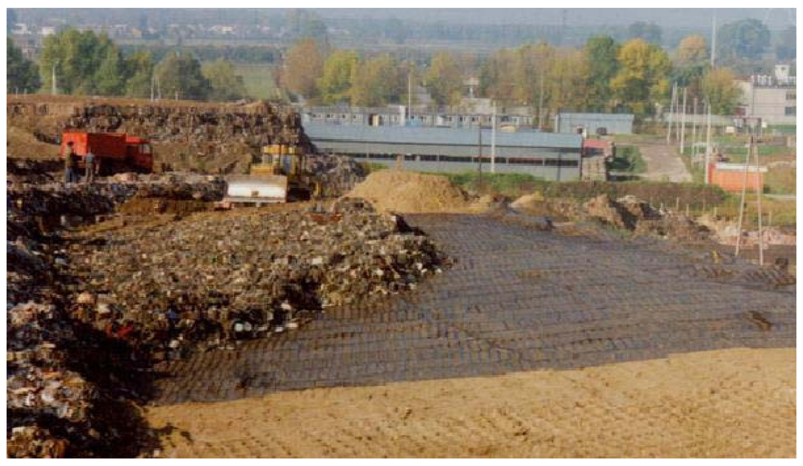
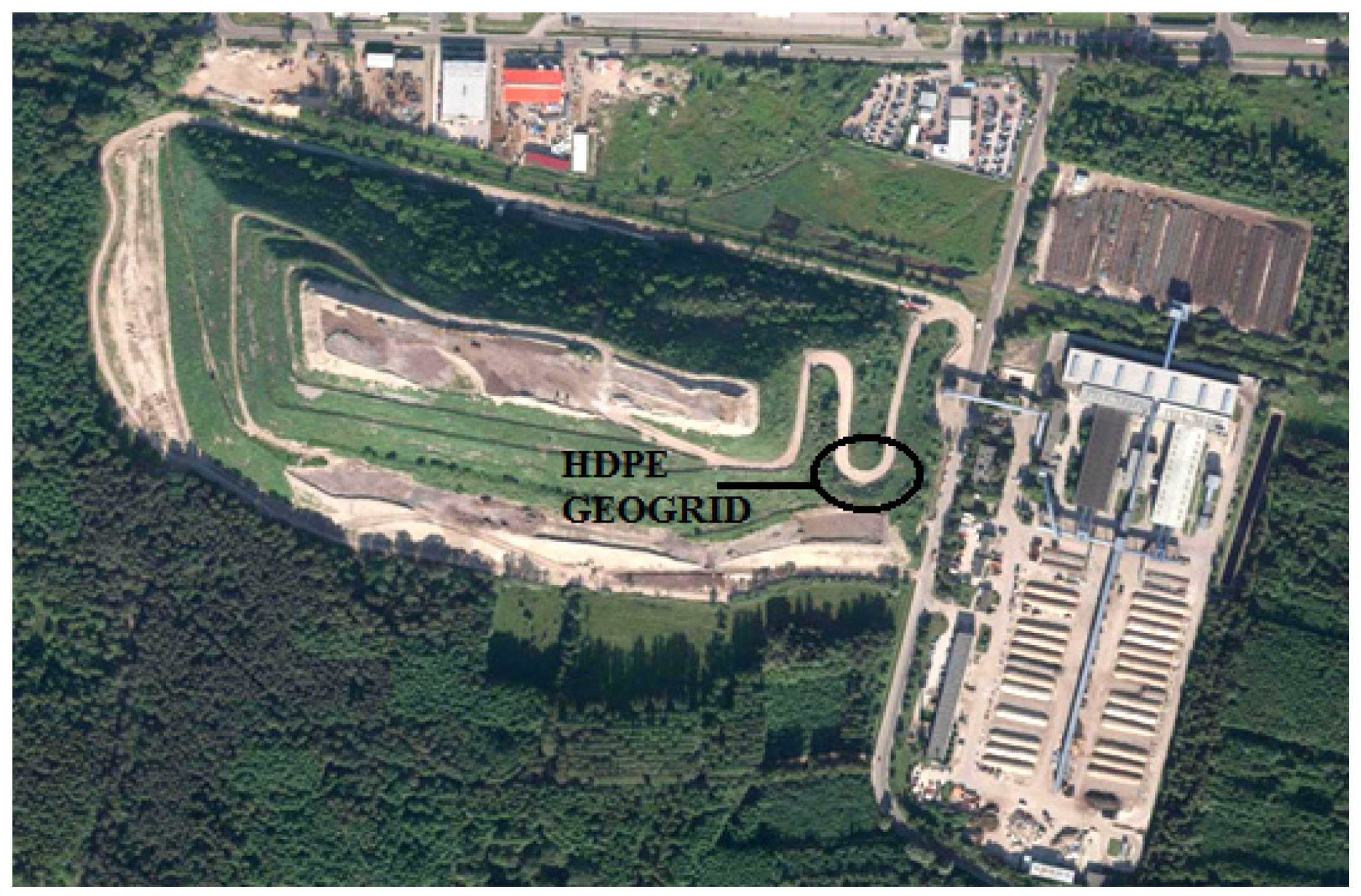
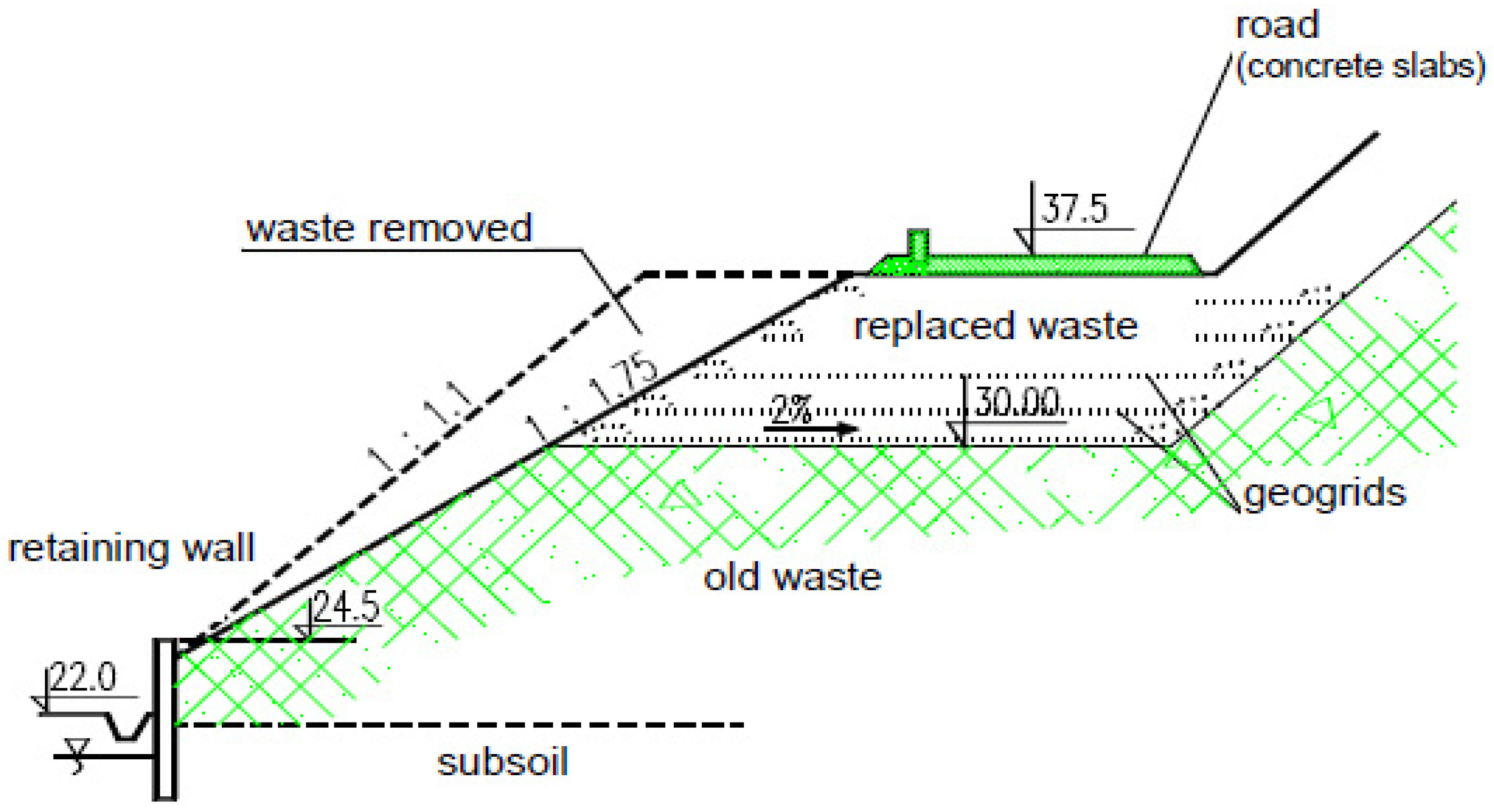
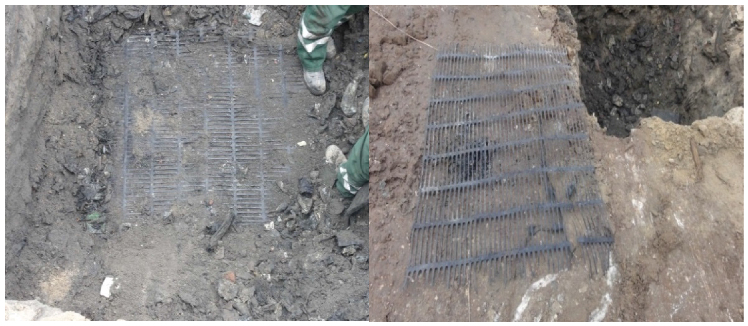
2.1. Location and Description of the Study Site

The Radiowo landfill covers an area of approximately 16 hectares at an altitude exceeding 60 m above ground level. The landfill is located along the north-western border of Warsaw in Poland (Figure 1).
From 1961 to 1991, mainly municipal waste was deposited there, and since 1992, it has become a structure that receives ballast waste from a composting plant. The ballast waste was composed of 5% to 12% organic fraction (>10 mm) and approximately 4% mineral waste (>10 mm). The physical characteristics of the ballast waste are as follows: the average density in non-compacted waste is 0.15–0.70 Mg/m3; the average density of compacted waste is 0.8–1.4 Mg/m3; and the waste humidity is 15.5% to 28% [31].
For high and steep slopes, the key issue was to improve their stability. To this end, a number of engineering procedures were required: comprehensive investigation of the mechanical properties of the waste using different techniques, mechanical reinforcements of the slopes, changing the inclination of the slopes, determining the type of waste, provision of land next to the landfill and clarifying the formal status of the landfill for further development [32,33,34].
Reclamation works in the landfill began in 1993 (Figure 2). They included safety improvements in the geotechnical formations of the landfill body. To improve the conditions of the northern slope stability and to construct the main access road to the landfill, a retaining wall was constructed. Further carving of the slope and installation of a horizontal uniaxial HDPE geogrid were also proposed (Figure 3).
The reason for such heavy modifications was that space was very limited on the northern slope (land ownership issues).
In November 2013, three samples of geogrids were collected from the landfill after 20 years of service (sample size: length approximately 1.20 m, width approximately 1.0 m). The samples were excavated from the first layer of the structure (Figure 3) located along the access road to the landfill.
In this particular location, the HDPE geogrid was exposed not only to chemical and environmental impacts but also to mechanical loads caused by the slope itself and loading of the incoming trucks filled with waste. The samples were extracted using mechanical diggers. They were removed from the edge of the road near the concrete slabs. The top layer of sand and waste were also excavated in the same way.
However, in this case, the process was stopped when a distance of 0.3 m from the geosynthetics was reached. Then, the excavation was continued manually using a shovel to avoid damaging the geogrid. The sampling location is presented in Figure 4. After the sample was excavated, it was carefully raised and laid between two films of black PE and transported to the laboratory for further testing.

2.2. Materials

The main advantage of geogrids is their high tensile strength. This type of reinforcement solution began to be implemented in the late 1970s. The geogrid production process begins with an extruded sheet of polyethylene, which is perforated in a regular pattern. In controlled heating conditions, the sheet is stretched to a randomly oriented long chain. The molecules are drawn in an ordered and aligned state. The whole process is performed to increase the tensile strength and tensile stiffness of the polymer [35]. The main properties of the geogrid used in the landfill site are presented in Table 1.

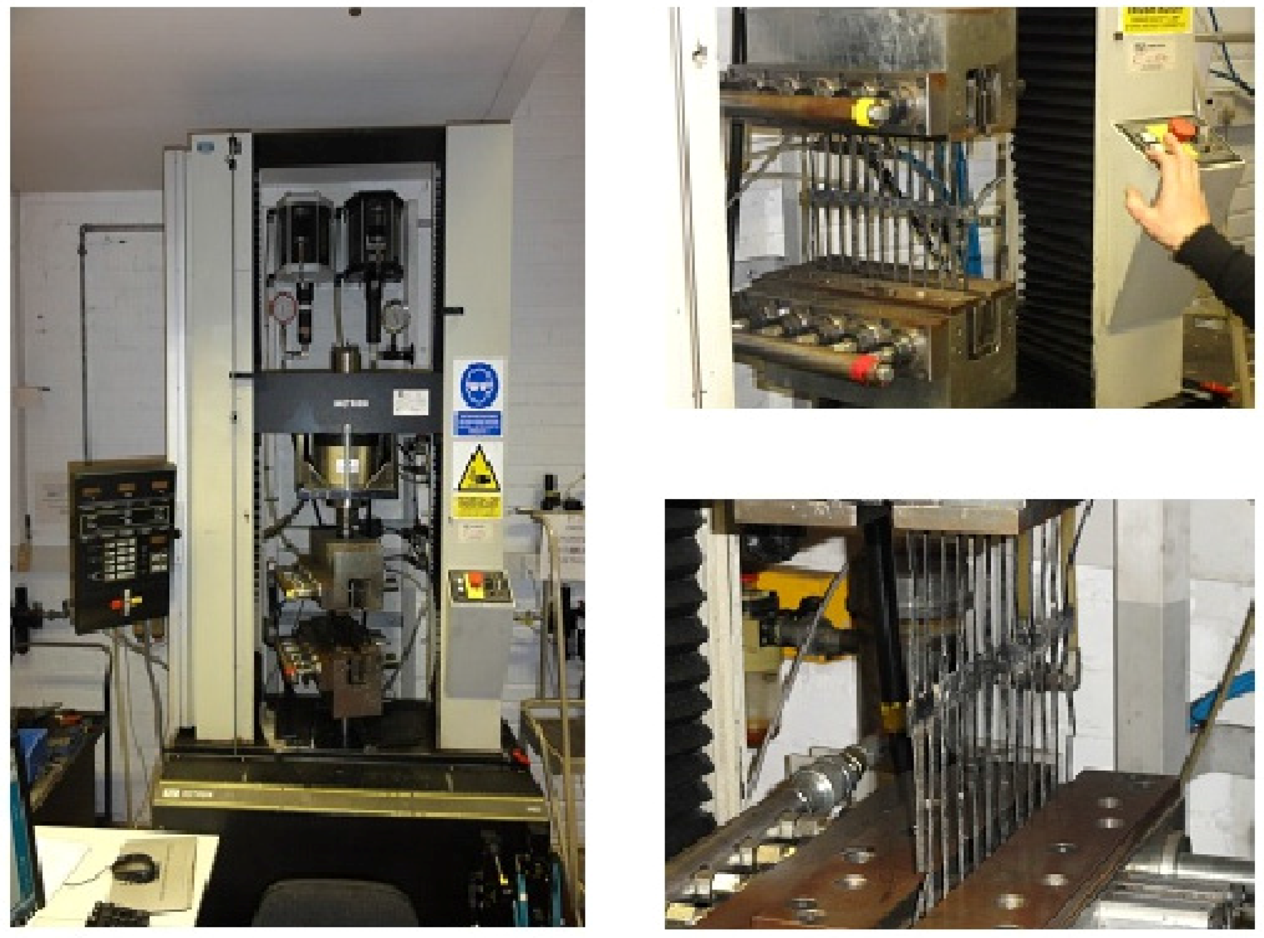
2.3. Tensile Strength Tests

When the reinforcement functions as geosynthetic material, the tensile strength and elongation at maximum load are the main challenges for appropriate assessment of the product stability, since the action of elevated or reduced temperature and humidity changes their properties. Tensile properties of virgin and 20-year-old geogrid samples were evaluated according to the EN ISO 10319 [36] testing method using an Instron universal testing machine (Figure 5). For each test, five specimens were used. The monotonic tensile tests were performed with a strain rate equal to 20%/min, as recommended by EN ISO 10319:2010.

2.4. Fourier Transform Infrared (FT-IR) Spectroscopy

FT-IR allows for the determination of the type of functional groups present in the structure of the test compound, which allows for the specification of the qualitative composition of the sample. The chemical structures of the virgin and aged geogrid samples were analyzed with an FT-IR spectrometer Perkin Elmer 2000 (Waltham, MA, USA) with Pike Gladiator (Madison, WI, USA) equipped with a KBr beamsplitter and DTGS (deuterated triglycine sulphate) detector, adapted for measurements in reflective mode over the absorption range of 400–4000 cm−1. The spectral resolution was 2 cm−1. Each spectrum was averaged from 32 scans.

2.5. Characteristics of Differential Scanning Calorimetry (DSC)

The change in crystallinity during ageing was measured using DSC. DSC measurements were carried out using a differential scanning calorimeter (DSC, Q2000 TA Instruments, New Castle, DE, USA) over a temperature range of −60–200 °C and a heating rate of 10 °C/min in nitrogen atmosphere (50 ± 5 mL/min). The mass of the sample taken for the tests was approximately 4 mg. The test sample was placed into an open DSC aluminum pan. For optimum heat flux, the highest possible contact area between the sample and the pan bottom should be achieved.
The DSC method allowed for the determination of the melting temperature and the enthalpy of fusion and for the comparison of the degree of crystallinity in individual samples.

2.6. Electron Microscopy Analysis

Scanning electron microscopy (SEM) uses a focused beam of high-energy electrons to generate a variety of signals on the surface of solid specimens. The signals derived from the electron-sample interactions reveal information about the sample, including its external morphology (texture) and chemical composition. SEM is capable of performing analyses at selected point locations in the sample. This approach is especially useful in the qualitative or semi-quantitative determination of the chemical composition (using a microprobe energy dispersive spectrometer, EDS).
Scanning electron microscopy (SEM) enables the observation of the topography of the test material. Likewise, the influence of chemical and environmental factors on the surface of the test material can be determined. The morphological structure of the samples was characterized by scanning electron microscopy (SEM Zeiss Ultra plus, Oberkochen, Germany). Before SEM analysis, the samples were coated with carbon by a sputter coater (SCD005, BAL-TEC, Balzers, Liechtenstein) under vacuum. The magnification of the images ranged from 500× to 5000×, captured with 2 kV accelerating voltage to investigate the surface.
To detect the presence of different elements in the top coating of the aged geogrids a scanning electron microscope (SEM Zeiss Ultra plus) with an EDS probe (Bruker Quantax 400, Berlin, Germany) was used. The magnification of the images ranged from 1000× to 5000×, captured with 15 kV accelerating voltage to investigate the surface.

3. Discussion

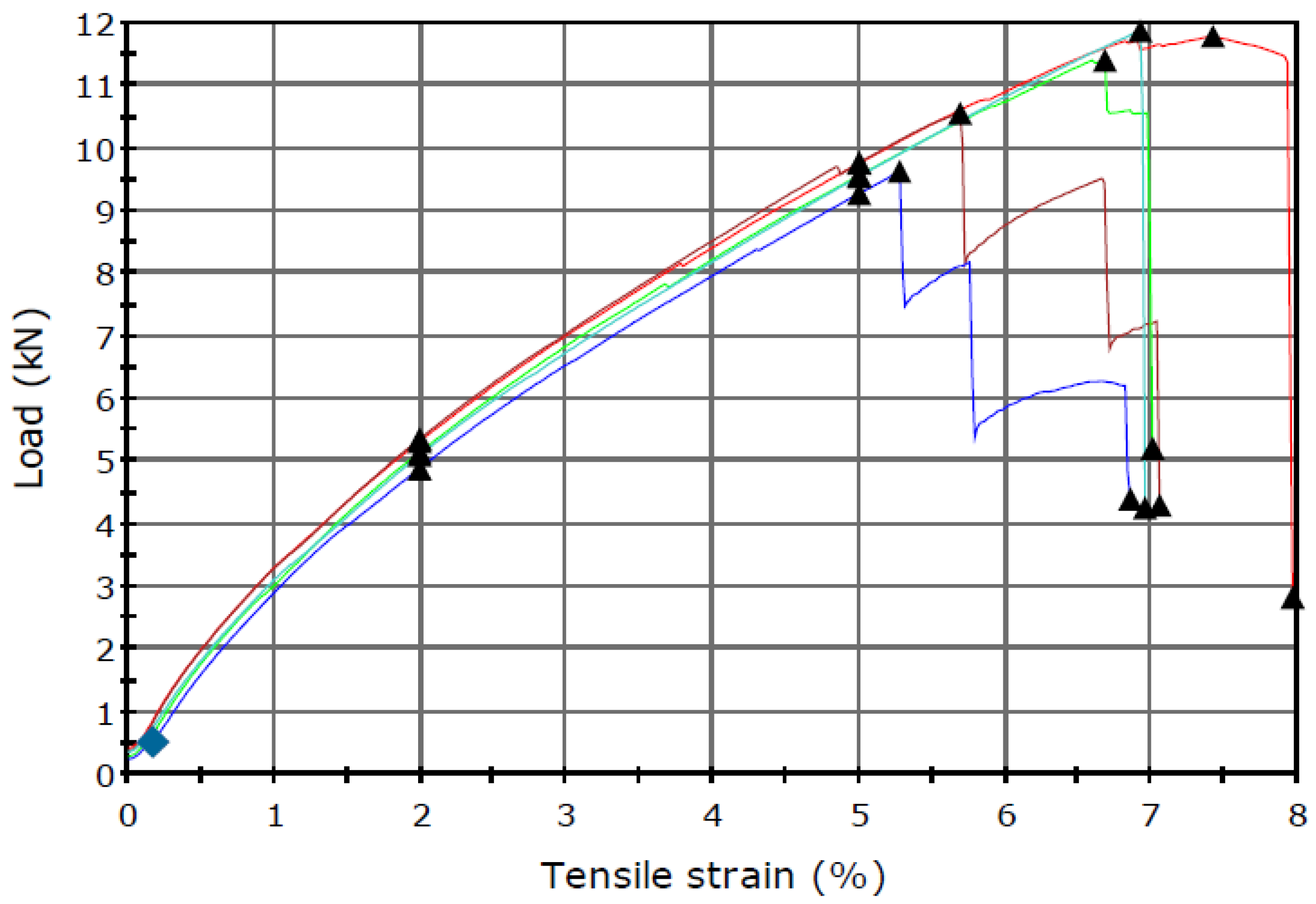
3.1. Tensile Strength Tests

Figure 6 and Table 2 show the results of the monotonic tensile tests performed with a strain rate equal to 20%/min, according to EN ISO 10319:2010.
The sample of the geogrid in a tensile test must be selected using the standard recommendation (samples that had mechanical damage due to the exhuming work were rejected). Figure 6 shows graphs and values for five samples taken from the geogrid after 20 years of service, and the average value for the five samples is 48.92 kN/m. Given that the geogrid is mostly exposed to mechanical factors during embedding, this measured value of tensile strength should be considered to be a relatively high value, preserving nearly 90% of the initial value (Table 2).
The summary of the results obtained for samples of new (virgin) geogrid and for a sample removed from the landfill 20 years after installation is presented in Table 2.
Twenty years ago, when geogrid reinforcements were planned and installed at the Radiowo site, a fairly conservative estimation of tensile strength of 22 kN/m (for the temperature of 10 °C) was given. This value was diminished by a security factor, which at that time, was assumed to be equal to 1.35. The reduction factor due to mechanical damage during installation for size fractions greater than 75 mm was 1.75. Therefore, the safe design strength of the geogrid for the SR55 (symbol assigned by the manufacturer) fraction above 75 mm was accepted to be 22/(1.75 × 1.35) = 9.31 kN/m.

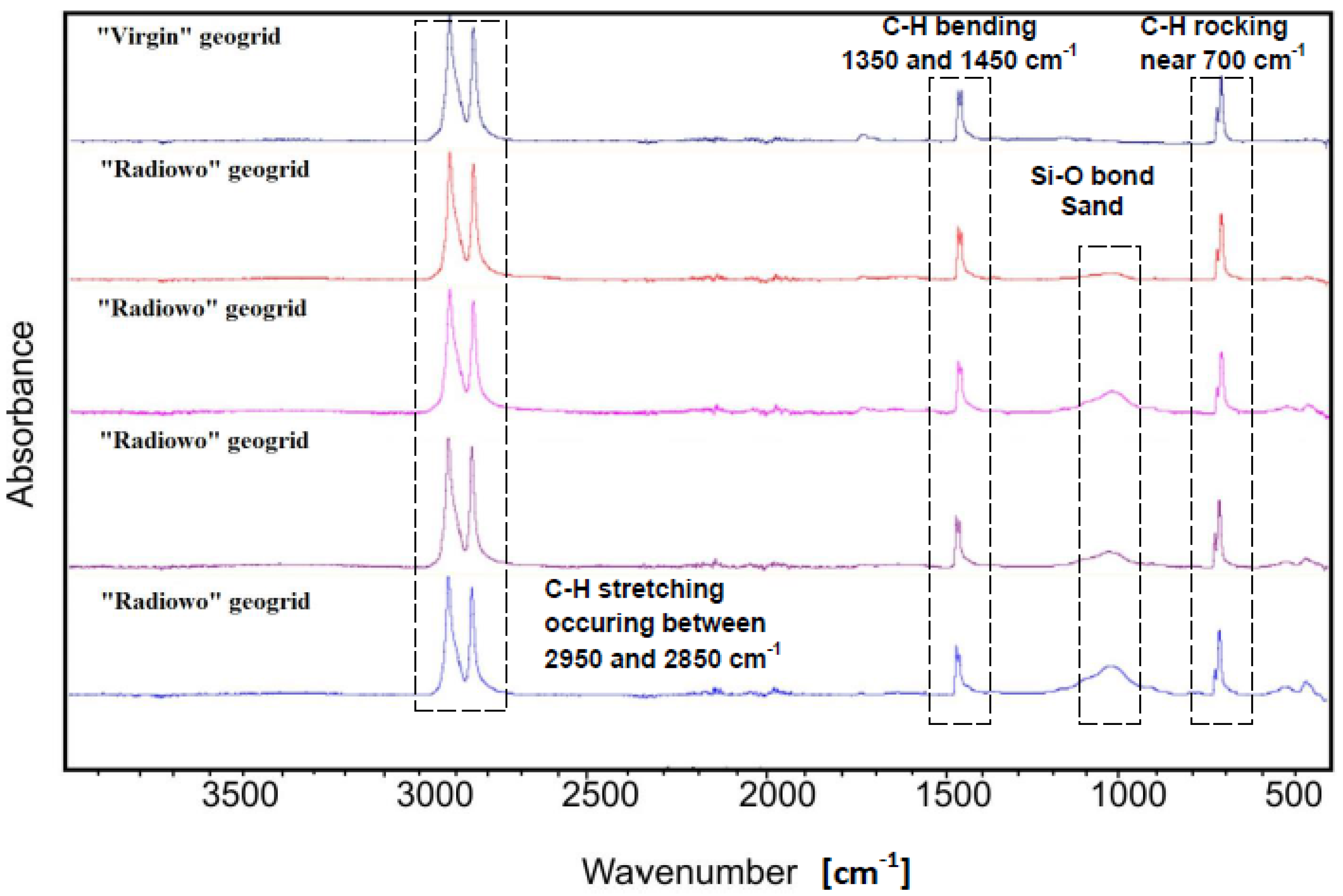
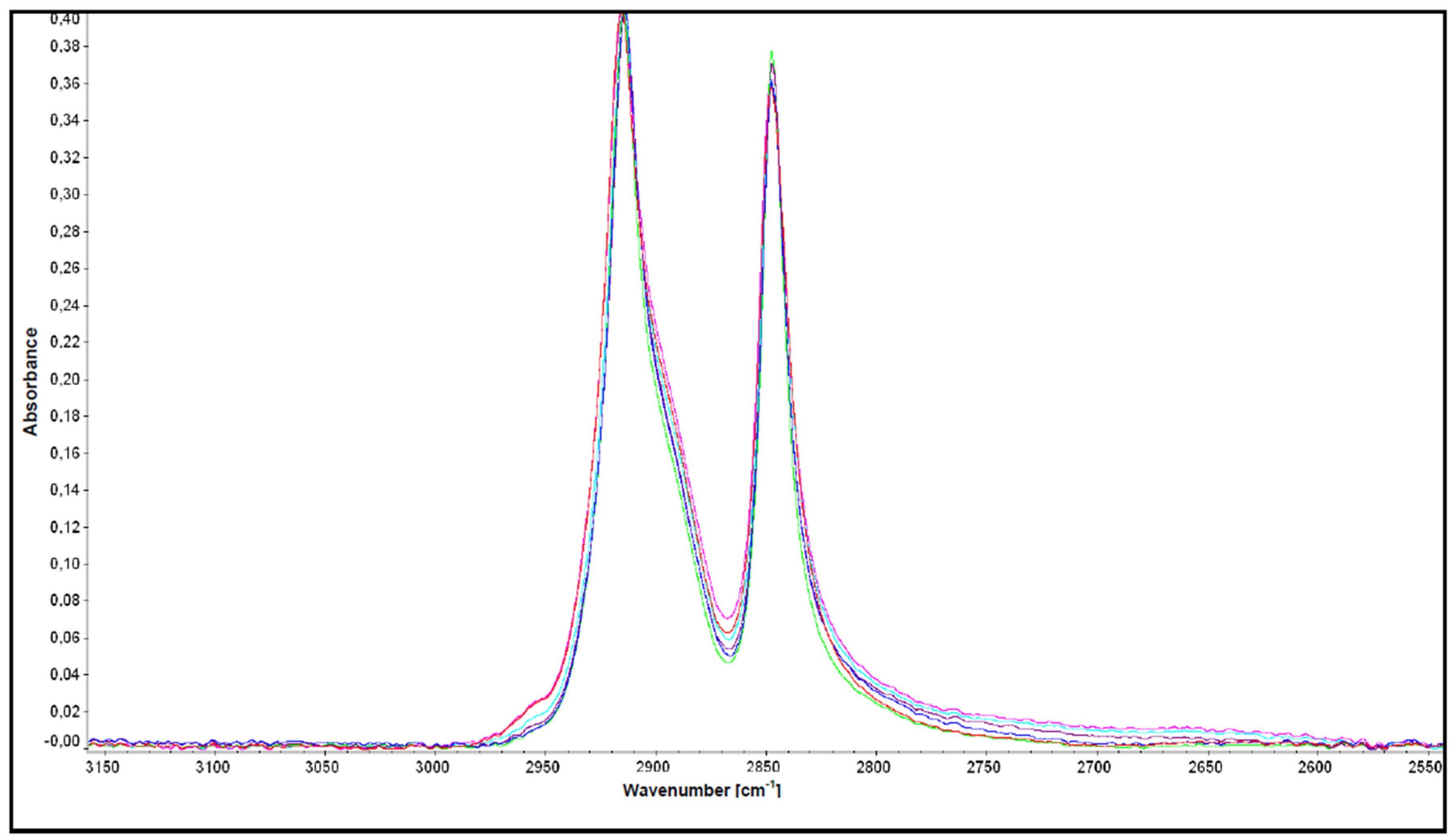
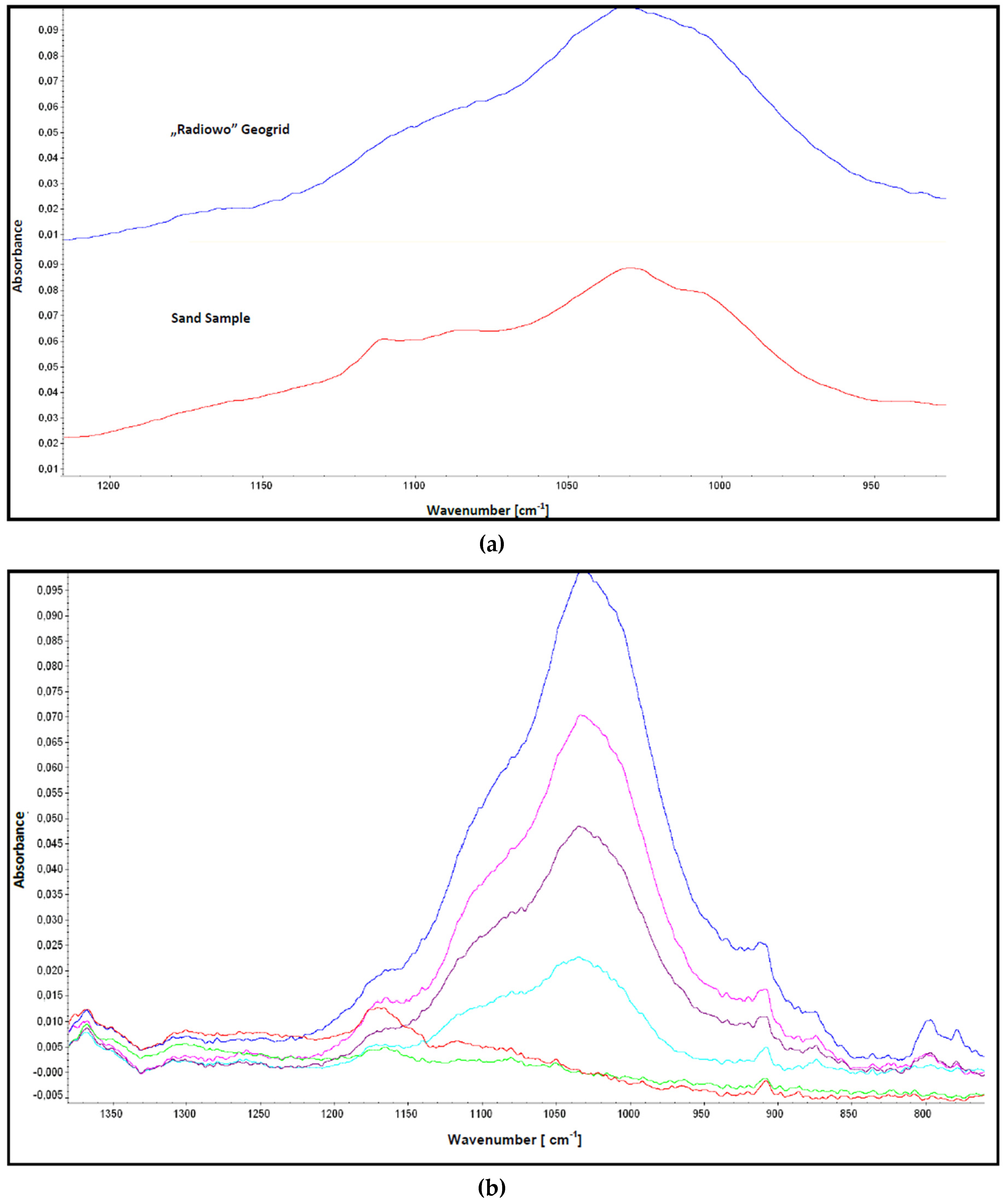
3.2. FT-IR Spectroscopy

It is generally accepted that the rate of chemical reactions in solid polymers may change significantly under the influence of external or internal stresses. On one hand, the rate may change due to substantial changes in the structural and physical parameters of a polymer subjected to the action of mechanical stresses (molecular conformation, free volume in the polymer, changes in the permeability and diffusion of the low-molecular mass substances). On the other hand, stresses may directly affect the reactivity of deformed macromolecules, thereby altering the effective activation energies for chemical reactions [37]. Furthermore, the high testing temperatures may induce morphological changes in the polymeric product, which can affect the kinetics of oxidative degradation, leading to the formation of hydroxyls, carbonyl and carboxylic groups, ethers, peroxides and hydroperoxides. FT-IR spectroscopy was used to identify oxygen bearing groups, which may be formed during localized ageing processes in the immediate environment of slowly growing cracks in the HDPE under static loads (Figure 7).
Figure 7 shows the FT-IR spectra of new (virgin) and aged HDPE geogrids. For both materials (geogrid “virgin” and geogrid “Radiowo”), three absorption bands (characteristic of polyethylene) related to the vibrational modes of the C-H bond can be observed, namely, C-H stretching (2950–2850 cm−1), C-H bending (1350–1450 cm−1) and C-H rocking (near 700 cm−1). Besides the aforementioned C-H absorption bands, the FT-IR spectrum of the HDPE geogrid “Radiowo” shows an absorption band at approximately 1030 cm−1.
In Figure 8, the FT-IR spectra of the extended region 2750–3000 cm−1 clearly show that there are no visible differences in the virgin and aged geogrid samples.
In Figure 9a shows the spectra in the region of 800–1350 cm−1 for the aged geogrid samples. Since these spectra were collected in reflective mode, the topmost spectrum shows the composition of the topmost layer of an aged geogrid sample. Subsequent spectra were collected downward from the topmost layers of the studied geogrids, which were removed systematically with a cutting knife. A decrease in the intensity of the band can be observed at approximately 1050 cm−1, which can be attributed to the Si-O bond present in a typical fine sand (Figure 9b). These spectra suggest the slow penetration of fine sand particles into the geogrid polymer structure. After removal of several layers, a small absorption band at approximately 1150 cm−1 can still be observed, which can be attributed to silica added as a filler to the HDPE matrix.
Absorption bands originating from the oxidation of the HDPE matrix were not observed. Peaks from the OH groups (approximately 3300–3500 cm−1) and strong absorptions from the carbonyl C = O bonds (1700–1750 cm−1 region) were not detected. This observation confirms the strong resistance of the HDPE matrix against oxidation, and its high chemical resistance under the service conditions.

3.3. Differential Scanning Calorimetry Results (DSC)

Crystallinity influences physical and mechanical properties such as yield stress, modulus of elasticity, impact resistance, density, permeability and melting point [38,39]. The melting point (Tm) and the melting enthalpy (ΔH) were measured, and the percentages of crystallinity were determined using the enthalpy of melting for polyethylene at 100% crystallinity, ΔH0 = 294 J/g [40]. The values obtained from the DSC tests are collected in Table 3. This increase in crystallinity may be attributed to the process of physical aging, in which the geogrids attempt to establish an equilibrium from its as-manufactured non-equilibrium state [38]. The results reveal that the degree of crystallinity for the aged samples is higher than the crystallinity of the new (virgin) samples.

3.4. Electron Microscopy Analysis

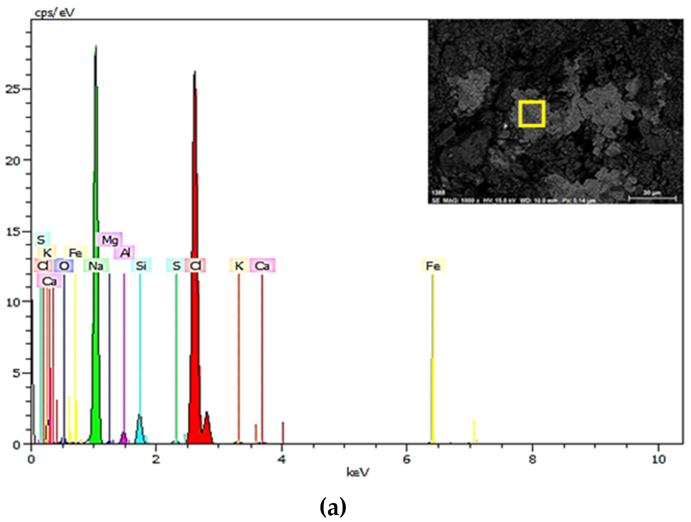
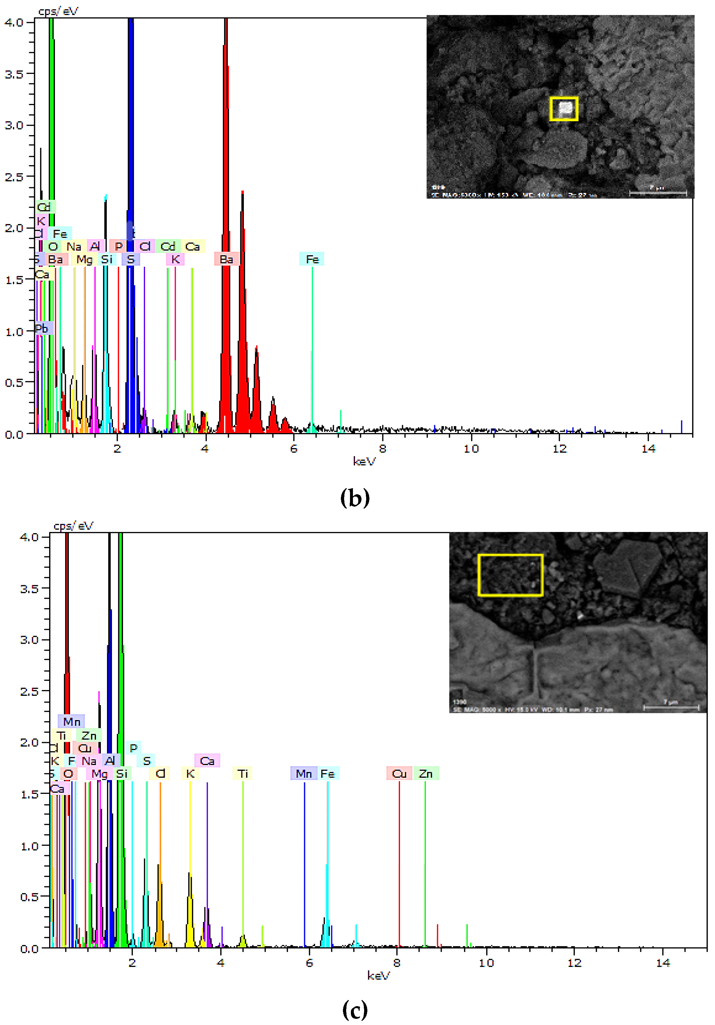
3.4.1. SEM-EDS Observations of Geogrids

SEM analyses were performed with an attached EDS probe to detect the presence of different elements in the top coating of the aged geogrids. EDS spectra were taken from selected (rectangular) areas of the samples.
Figure 10 reveals the presence of mainly SiO2 (sand) and Al2O3 (bauxite) and a minor contribution of other elements, such as iron, potassium, magnesium, sodium, calcium, and barium. These elements occur in the form of oxides, chlorides and sulfates. Table 4 presents the composition of elements in the coating layer of aged geogrids (% w/w).

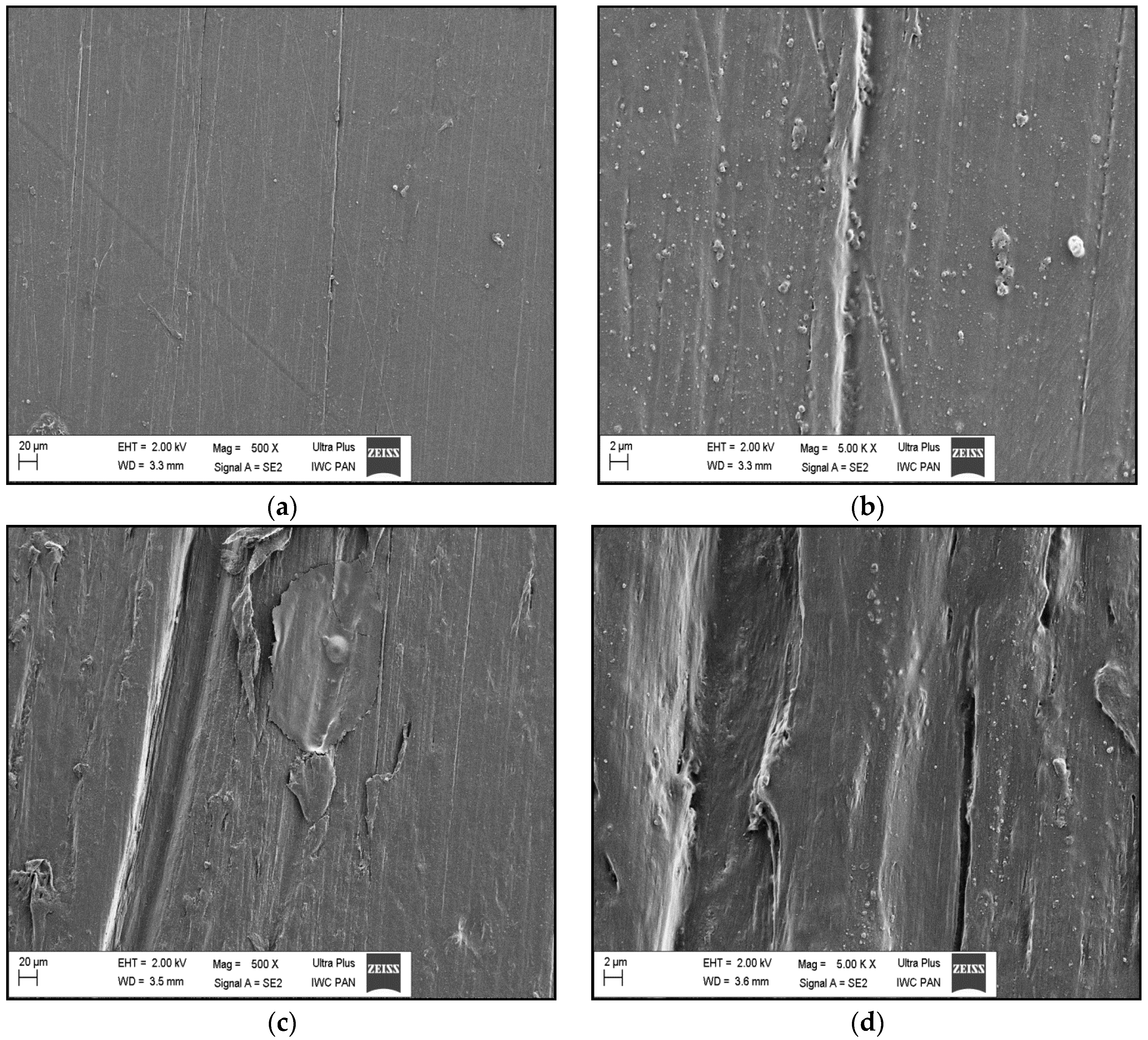
3.4.2. SEM Observations

Figure 11 presents SEM images of virgin and aged geogrid samples. SEM images of new and aged HDPE samples did not reveal significant changes in the surface analysis of the HDPE polymer. These observations additionally confirm the high resistance of this material after 20 years of continuous service.

4. Conclusions

Generally, HDPE geogrids analyzed after 20 years of continuous service in a municipal waste landfill display only minor changes compared to the virgin material. More detailed changes in the mechanical and physicochemical properties are as follows.
There is no significant deterioration of the geogrid mechanical parameters. The mechanical strength of the geogrid samples after 20 years of service decreased by approximately 10%–20% compared to the virgin geogrid samples.
In the FT-IR spectra of the topmost layer of the aged samples, there are no significant changes compared to the topmost layer of the virgin samples. This indicates the strong chemical resistance of the HDPE material, which is able to withstand environmental conditions during at least 20 years of service in a landfill.
The DSC results indicate that a slow crystallization processes takes place within the aged HDPE geogrid samples. An increase in the degree of crystallinity for the aged samples can be observed.
Elemental analysis of the coating on PE geogrids retrieved from the Radiowo landfill after 20 years of service indicates that salts of sodium, calcium, aluminum, potassium, iron, copper, zinc, and barium, mainly as oxides, sulfates and chlorides, are deposited on the surface of the material.
SEM images of samples taken from the landfill show the influence of mechanical interactions on the surface of the geogrids, while there were no significant changes related to the impact of environmental and chemical factors.

Author Contributions

A.K., E.K. and W.F. conceived and designed the experiments; A.K. and J.K. performed the experiments; E.K., A.K. and W.F. analyzed the data; A.K. and J.K. contributed reagents/materials/analysis tools; A.K. and E.K. wrote the paper.

Conflicts of Interest

The authors declare no conflict of interest.

References

  1. Koerner, R.M. Designing with Geosynthetics, 5th ed.; Prentice Hall: Englewood Cliffs, NJ, USA, 2005. [Google Scholar]
  2. Hsuan, Y.G.; Li, M. Temperature and pressure effects on the oxidation of high-density polyethylene geogrids. Geotext. Geomembr. 2005, 23, 55–75. [Google Scholar] [CrossRef]
  3. Kim, D.; Ha, S. Effects of Particle Size on the Shear Behavior of Coarse Grained Soils Reinforced with Geogrid. Materials 2014, 7, 963–979. [Google Scholar] [CrossRef]
  4. Webster, S.L. Geogrid Reinforcement Base Courses for Flexible Pavements for Light Aircraft; Technical Report GL-93-6; U.S. Army Engineers Water-Ways Experiment Station: Vicksburg, MS, USA, 1993. [Google Scholar]
  5. Kawalec, J. Stabilisation of the subsoil with geogrids (in Polish). Inżynieria Morska Geotech. 2010, 4, 522–530. [Google Scholar]
  6. Moraci, N.; Cardile, G. Influence of cyclic tensile loading on pullout resistance of geogrids embedded in a compacted granular soil. Geotext. Geomembr. 2009, 27, 475–487. [Google Scholar] [CrossRef]
  7. Peng, F.L.; Li, F.L.; Tan, Y.; Kongkitkul, W. Effects of Loading Rate on Viscoplastic Properties of Polymer Geosynthetics and Its Constitutive Modeling. Polym. Eng. Sci. 2010, 50, 550–560. [Google Scholar] [CrossRef]
  8. Kongkitkul, W.; Hirakawa, D.; Tatsuoka, F.; Uchimura, T. Viscous deformation of geosynthetic reinforcement under cyclic loading conditions and its model simulation. Geosinthetic Int. 2004, 11, 73–99. [Google Scholar] [CrossRef]
  9. Moraci, N.; Cardile, G. Deformative behaviour of different geogrids embedded in a granular soil under monotonic and cyclic pullout loads. Geotext. Geomembr. 2012, 32, 104–110. [Google Scholar] [CrossRef]
  10. Bathurst, R.J.; Cai, Z. In-isolation cyclic load-extensionbehavior of two geogrids. Geosinthetic Int. 1994, 1, 3–17. [Google Scholar]
  11. Sawicki, A.; Kazimierowicz-Frankowska, K. Influence of strain rate on the load-strain characteristics of geosynthetics. Geosinthetic Int. 2002, 9, 1–19. [Google Scholar] [CrossRef]
  12. Palmeira, E.M. Soil geosynthetic interaction. Modeling and analysis. Geotext. Geomembr. 2009, 27, 368–390. [Google Scholar] [CrossRef]
  13. Geosynthetics—Guidelines for the Assessment of Durability; International Organization for Standardization: Geneva, Switzerland, 2008; ISO/TS 13434:2008.
  14. Recommendations for Design and Analysis of Earth Structures Using Geosynthetic Reinforcements; Ernst & Sohn Verlag, EBGEO: Berlin, Germany, 2011.
  15. Code of Practice for Strengthened/Reinforced Soils and Other Fills; British Standards Institution: London, UK, 2010; BS8006-1:2010.
  16. Geogrids for Reinforced Soil Retaining Wall and Bridge Abutment System; British Board Agreement Technical Approval: Blackburn, UK, 2010; BBA 99/R109.
  17. Hufenus, R.; Rüegger, R.; Flum, D.; Sterba, I.J. Strength reduction factors due to installation damage of reinforcing geosynthetics. Geotext. Geomembr. 2005, 23, 55–75. [Google Scholar] [CrossRef]
  18. Hsuan, Y.G.; Koerner, R.M. Antioxidant depletion lifetime in high density polyethylene geomembranes. J. Geotech. Geoenviron. Eng. ASCE 1998, 124, 532–541. [Google Scholar] [CrossRef]
  19. Rowe, R.K.; Sangam, H. Durability of HDPE geomembranes. Geotext. Geomembr. 2002, 20, 77–95. [Google Scholar] [CrossRef]
  20. Carneiro, J.R.; Almeida, P.J.; Lopes, M.L. Resistance of high-density polyethylene geonets against chemical ageing. In Proceedings of the 6th International Congress on Environmental Geotechnics, New Delhi, India, 7–12 November 2010.
  21. Rowe, K.; Islam, M.Z.; Hsuan, Y.G. Leachate chemical composition effects on OIT depletion in an HDPE geomembrane. Geosinthetics Int. 2008, 15, 2. [Google Scholar] [CrossRef]
  22. Kay, D.; Blond, E.; Mlynarek, J. Geosynthetics durability: A polymer chemistry. In Proceedings of the 57th Canadian Geotechnical Conference, Quebec City, QC, Canada, 24–26 October 2004.
  23. Petermann, J.; Miles, M.; Gleiter, H. Growth of polymer crystals during annealing. J. Macromol. Sci. Phys. 1976, 12, 393–404. [Google Scholar] [CrossRef]
  24. Mathur, A.; Netravali, A.N.; O′Rourke, T.D. Chemical aging effect on the physico–mechanical properties of polyester and polypropylene geotextiles. Geotext. Geomembr. 1994, 13, 591–626. [Google Scholar] [CrossRef]
  25. Koerner, R.M.; Hsuan, Y.D.; Lord, A.E. Remaining Technical Barriers to Obtain General Acceptance of Geosynthetics. In ASCE Geotechnical Special Publication; The American Society of Civil Engineers: New York, NY, USA, 1986. [Google Scholar]
  26. Elias, V.; Kenneth, P.E.; Fishman, L.; Christopher, B.R.; Berg, R.R. Corrosion/Degradation of Soil Reinforcements for Mechanically Stabilized Earth Walls and Reinforced Soil Slopes; U.S. Department of Transportation Federal Highway Administration: Woodbury, MN, USA, 2009; Publication No. FHWA-NHI-09-087.
  27. Leflaive, E. Durability of geotextiles: The French experience. Geotext. Geomembr. 1988, 7, 23–31. [Google Scholar] [CrossRef]
  28. Pouig, J.; Blivet, J.C.; Pasquet, P. Earth reinforced fill with synthetic fabric. In Proceedings of the International Conference on use of fabrics in Geotechniques, Paris, France, 20–22 April 1977.
  29. Bell, J.R.; Steward, J.E. Construction and observations of fabric soil walls. In Proceedings of the International Conference on use of fabrics in Geotechniques, Paris, France, 20–22 April 1977.
  30. Bell, J.R.; Szymoniak, T.; Thommen, G.R. Construction of a steep sided geogrid retaining wall for an Oregon Coastal Highway. In Proceedings of the Polymer Grid Reinforcement Conference, London, UK, 22–23 March 1984.
  31. Koda, E. Stability conditions improvement of the old sanitary landfills. In Proceedings of the 3th Internatonal Congress on Environment Geotechnics, Lisboa, Portugal, 7–11 September 1998.
  32. Koda, E.; Osiński, P. Application of alternative methods of slope stability improvements on landfills. In Proceedings of the XVI European Conference on Soil Mechanics and Geotechnical Engineering “Geotechnical Engineering for Infrastructure and Development”, Edinburgh, UK, 13–17 September 2015.
  33. Koda, E.; Szymański, A.; Wolski, W. Field and laboratory experience with the use of strip drains in organic soils. Can. Geotech. J. 1993, 30, 308–318. [Google Scholar] [CrossRef]
  34. Koda, E. Anthropogenic waste products utilization for old landfills rehabilitation. Ann. Wars. Univ. Life Sci. Land Reclam. 2012, 44, 75–88. [Google Scholar] [CrossRef]
  35. Tensar. The Long-Term Performance of Tensar Geogrids; Tensar/Nelton LTD: Blackburn, UK, 1990. [Google Scholar]
  36. Geosynthetics—Wide-Width Tensile Test; International Organization for Standardization: Geneva, Switzerland, 2010; ISO 10319:2010.
  37. Pinter, G.; Haager, M.; Wolf, C.; Lang, R.W. Thermo-oxidative degradation during creep crack growth of PE-HD grades as assessed by FT-IR spectroscopy. Macromol. Symp. 2004, 217, 307–316. [Google Scholar] [CrossRef]
  38. Rowe, R.K.; Rimal, S.; Sangam, H. Ageing of HDPE geomembrane exposed to air, water and leachate at different temperatures. Geotext. Geomembr. 2009, 27, 137–151. [Google Scholar] [CrossRef]
  39. Kong, Y.; Hay, J.N. The measurement of the crystallinity of polymers by DSC. Polymer 2002, 43, 3873–3878. [Google Scholar] [CrossRef]
  40. Wunderlich, B. Reversible crystallization and the rigid–amorphous phase in semicrystalline macromolecules. Prog. Polym. Sci. 2003, 28, 3383–3450. [Google Scholar] [CrossRef]
Figure 1. View of the Radiowo landfill where the northern and western slopes were reinforced by a high density polyethylene (HDPE) geogrid in 1993.
Applsci 07 00022 g001
Figure 2. The process of geogrid installation in the landfill (1993).
Applsci 07 00022 g002
Figure 3. Cross-section and reinforcements in the northern slope of the landfill [31].
Applsci 07 00022 g003
Figure 4. Geogrid HDPE samples collected after 20 years of service.
Applsci 07 00022 g004
Figure 5. Laboratory equipment for tensile testing.
Applsci 07 00022 g005
Figure 6. Tensile strength of an aged geogrid sample.
Applsci 07 00022 g006
Figure 7. Collected Fourier transform infrared (FT-IR) spectra of virgin geogrid samples and aged geogrid samples (Radiowo).
Applsci 07 00022 g007
Figure 8. Collected FT-IR spectra (2750–3000 cm−1 region) of virgin geogrid samples and aged geogrid samples (Radiowo).
Applsci 07 00022 g008
Figure 9. (a) Corrected spectra for aged geogrids samples and (b) corrected spectra for “sample sand” (silicates).
Applsci 07 00022 g009
Figure 10. Scanning electron microscopy (SEM) and energy dispersive spectrometer (EDS) analysis for the coatings in the geogrid samples 1 (a), 2 (b), 3 (c).
Applsci 07 00022 g010aApplsci 07 00022 g010b
Figure 11. (a,b) SEM images of a “virgin” geogrid sample and (c,d) an aged “Radiowo” geogrid sample.
Applsci 07 00022 g011
Table 1. Engineering properties of the uniaxial geogrid from Radiowo.
Geometry
Aperture size (mm × mm)16 × 140
Rib thickness (mm)0.95
CMD bar thickness (mm)2.5 ÷ 2.7
Rib width (mm)6.7
CMD bar width (mm)16
Weight (g/m2)500
Mechanical Properties
Tensile strength at 2% strain (kN/m)19.0
Tensile strength at 5% strain (kN/m)33.5
Peak tensile strength (kN/m)55
Yield point elongation (%)11.2
CMD—Cross-Machine Direction.
Table 2. Results from a wide range of tests for virgin (new) and aged geogrid samples.
Sample NumberSample before Installing (Virgin) (Declared Strength 55 kN/m)Samples 20 Years after Installation (Aged)
Mean Tensile Strength (kN/m)Mean Strain at Maximum Load (%)Mean Tensile Strength (kN/m)Mean Strain at Maximum Load (%)
160.779.5552.187.41
261.689.8046.745.69
360.799.3250.486.68
461.4510.0752.556.92
560.289.6642.635.28
Mean60.999.6848.926.40
Standard Deviation0.570.284.200.89
Coefficient of Variation (%)0.932.898.5813.86
Table 3. Differential scanning calorimetry (DSC) results for new (virgin-V) geogrid samples and aged (Radiowo-R) geogrid samples. ΔH: melting enthalpy; Tm: melting point; Wk: degree of crystallinity.
SampleΔH (J/g)Tm (°C)ΔHo (J/g)Wk (%)
HDPEV1153.3131.1529352
HDPEV2154.1130.1329352
HDPER1178.8129.7729360
HDPER2184.1130.2229362
HDPER3174.7129.7029359
HDPER4185.0129.6029362
Table 4. Percentage of elements in the coating layer of the geogrids.
Characteristic ElementsElemental Percentage (%) (a)Elemental Percentage (%) (b)Elemental Percentage (%) (c)
Ba-50.31
O3.6928.0144.37
Na38.101.271.92
Mg0.321.085.12
Al1.311.578.77
Si3.132.9718.40
P-0.070.29
S0.3111.682.44
Cl51.550.412.80
K0.460.432.91
Ca0.270.642.17
Ti--1.04
Mn--0.27
Fe0.861.496.60
Cu--1.11
Zn--1.78
Cd-0.06-
TOTAL100100100

