
A Study on the Control Performance of Electronic Differential System for Four-Wheel Drive Electric Vehicles


Abstract
:
1. Introduction
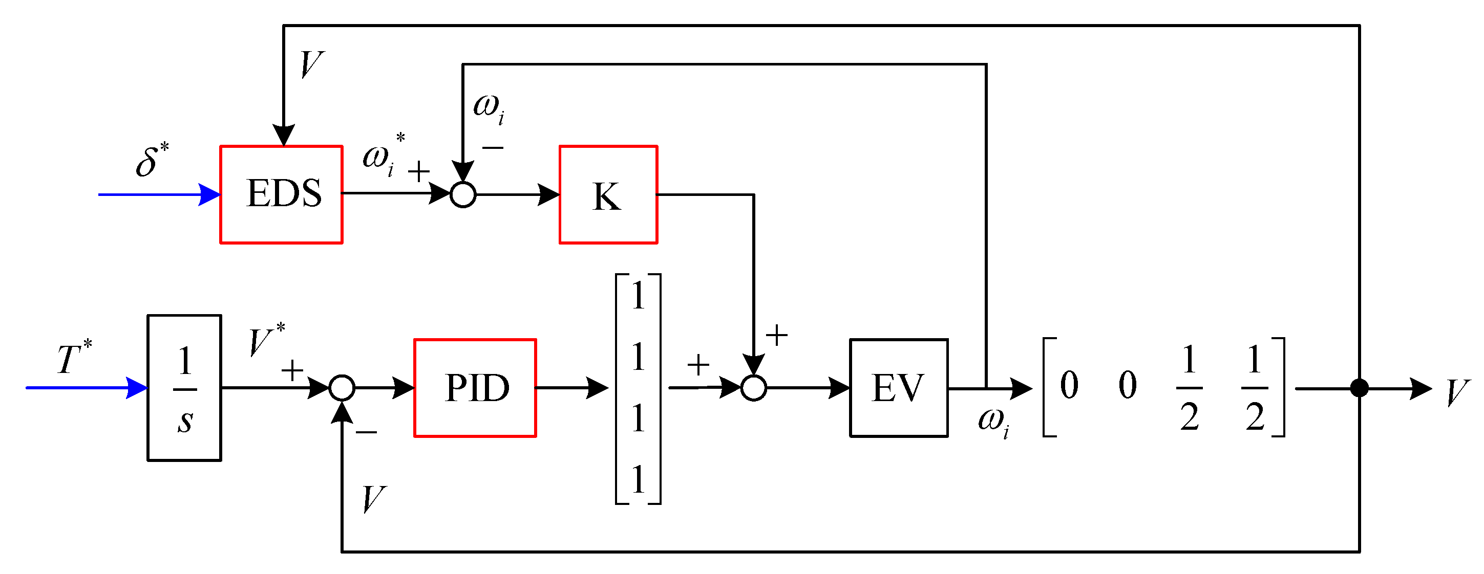
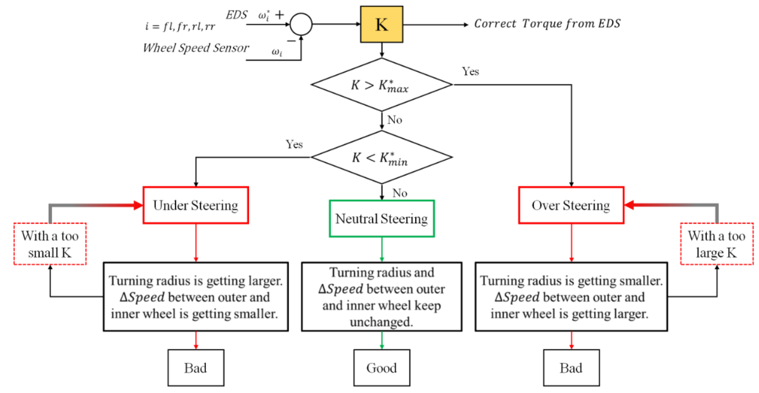
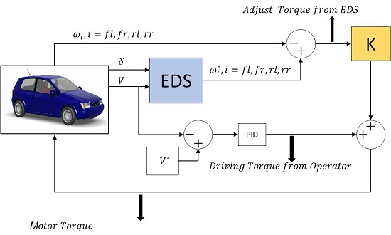
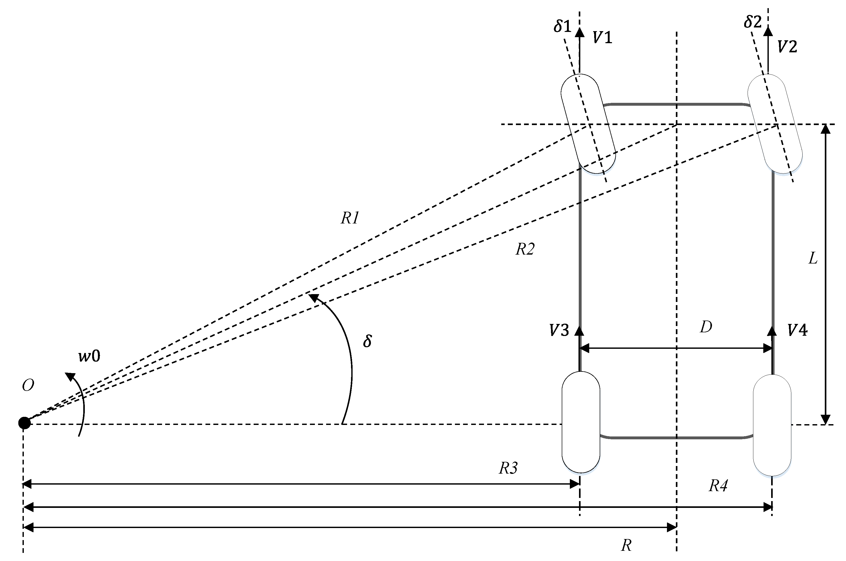
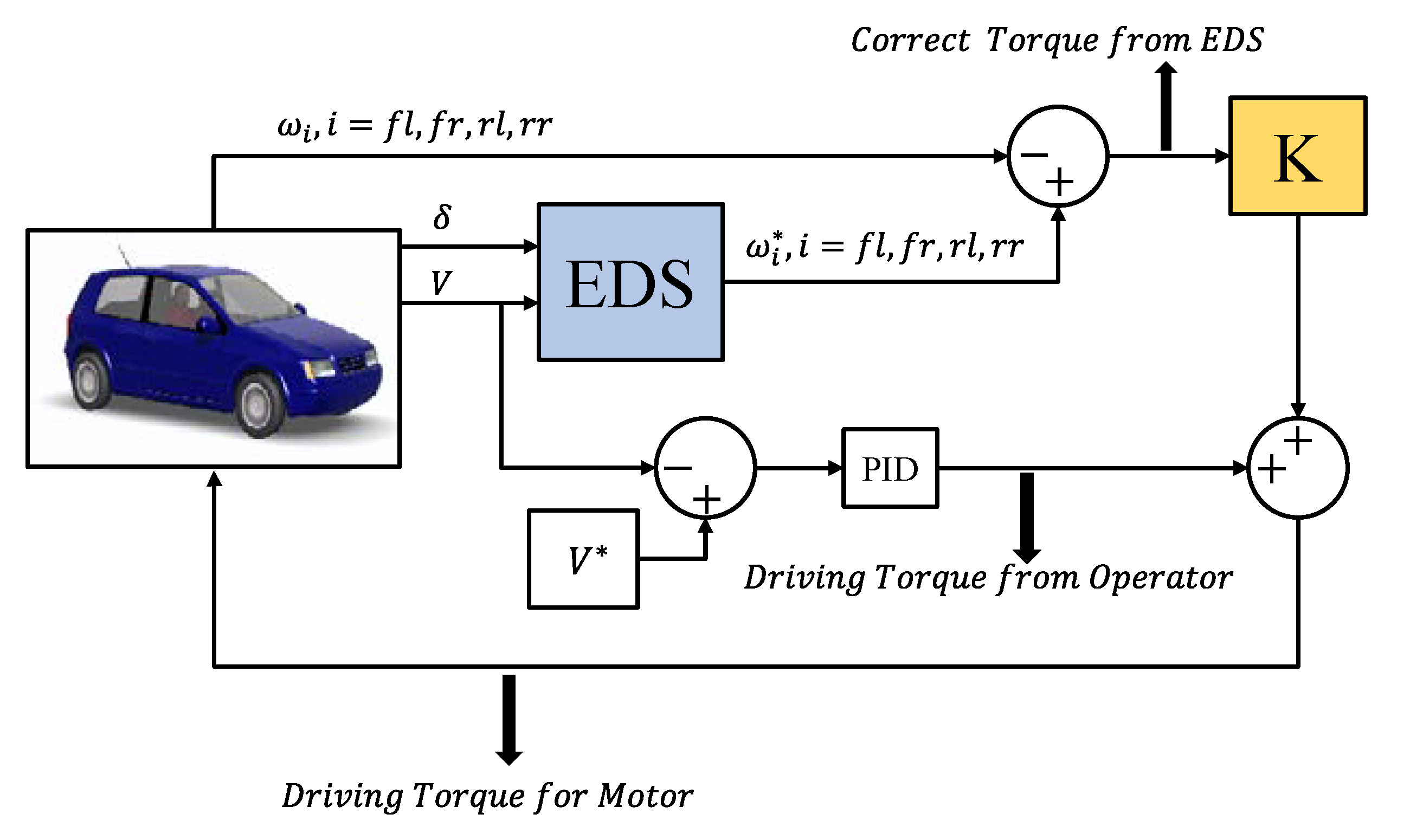
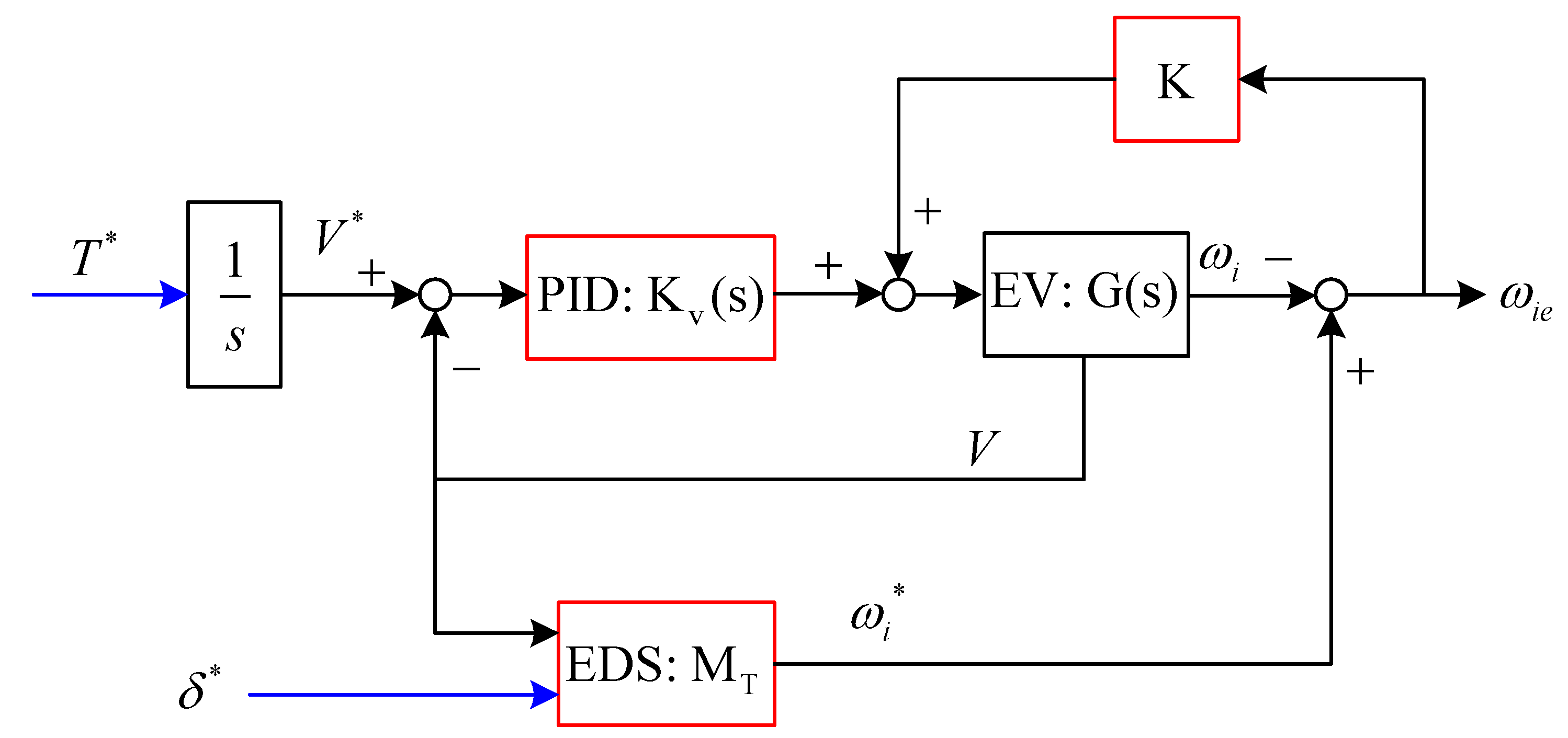
2. Modeling of EDS
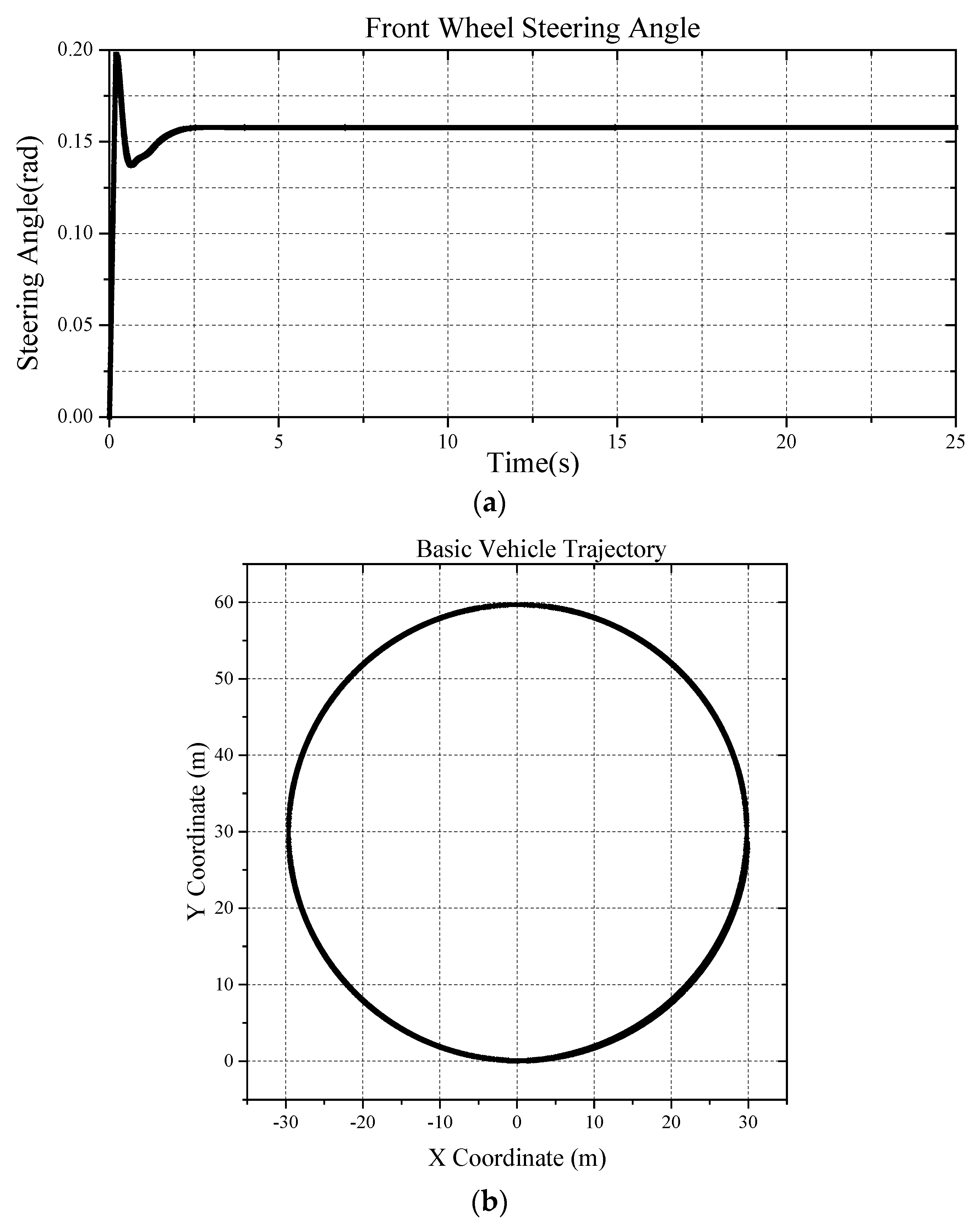
3. Simulation Setup
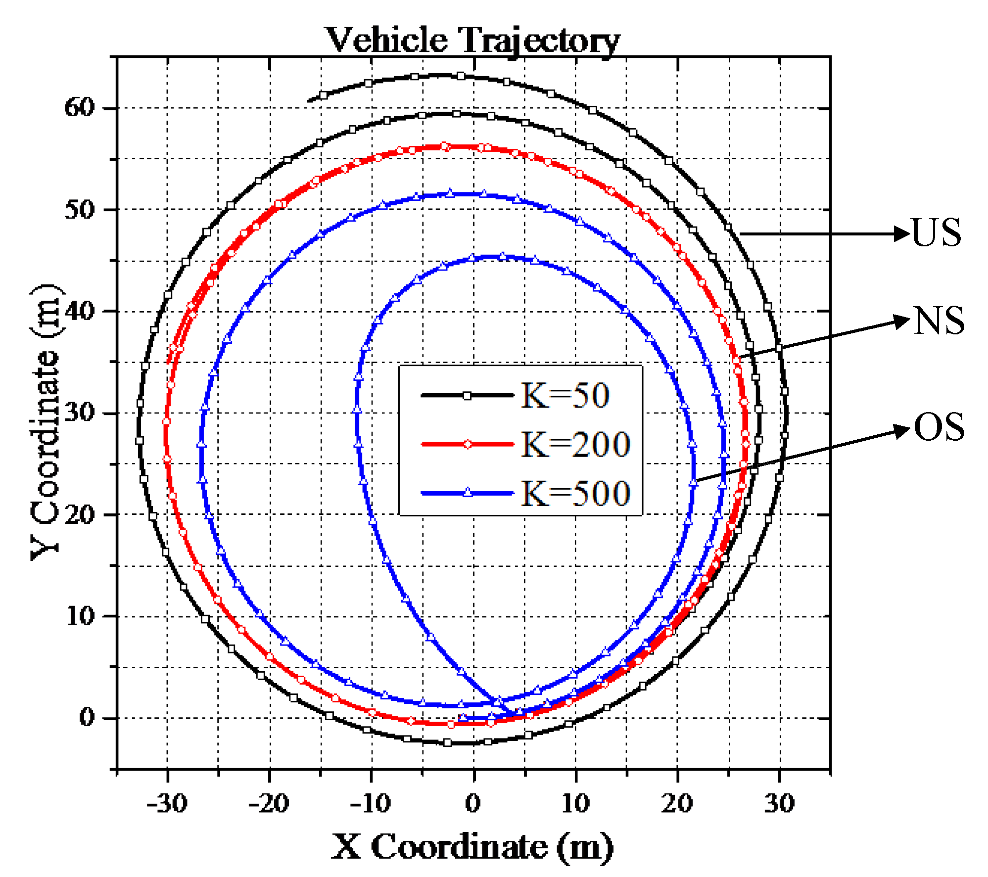
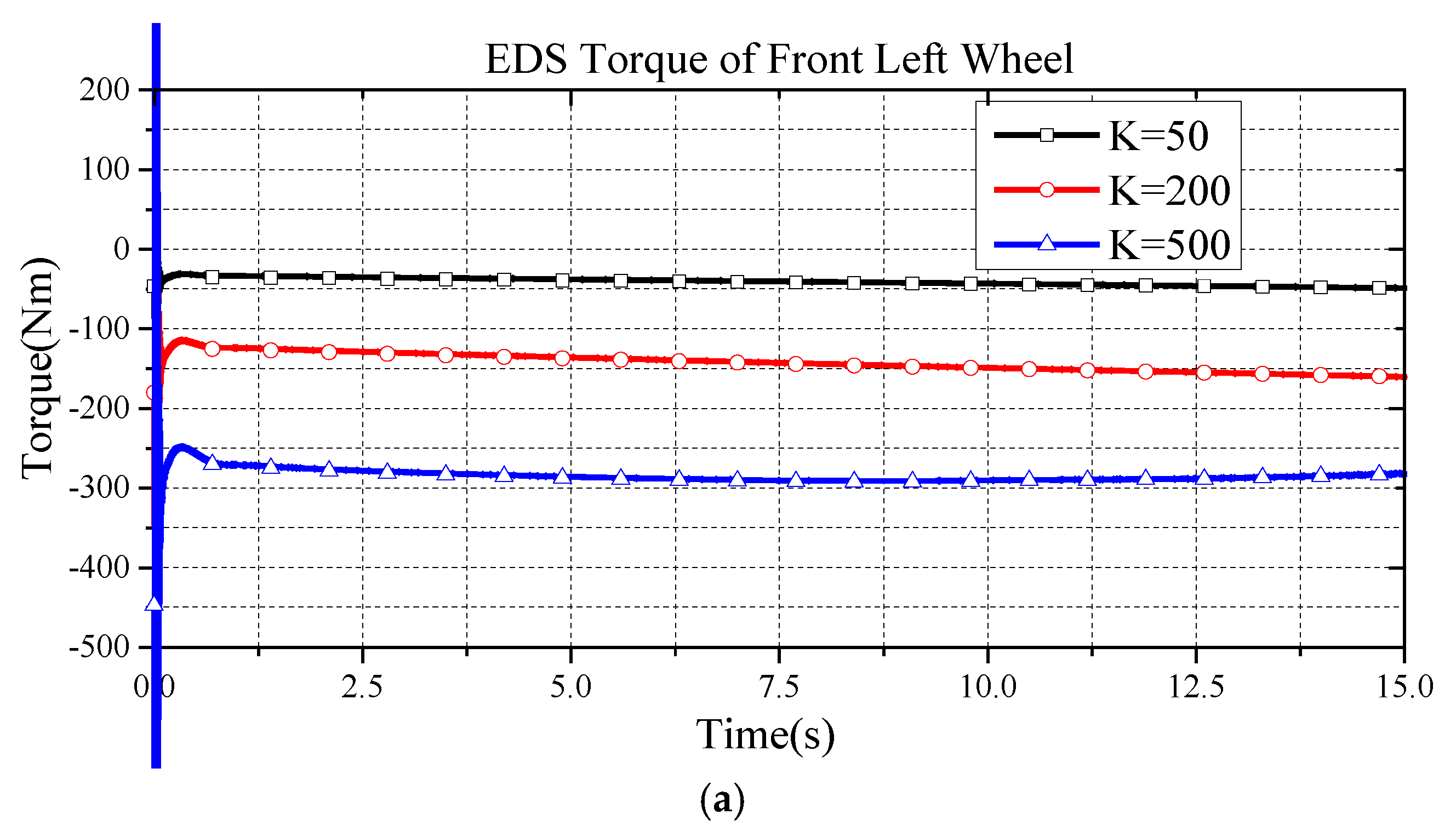
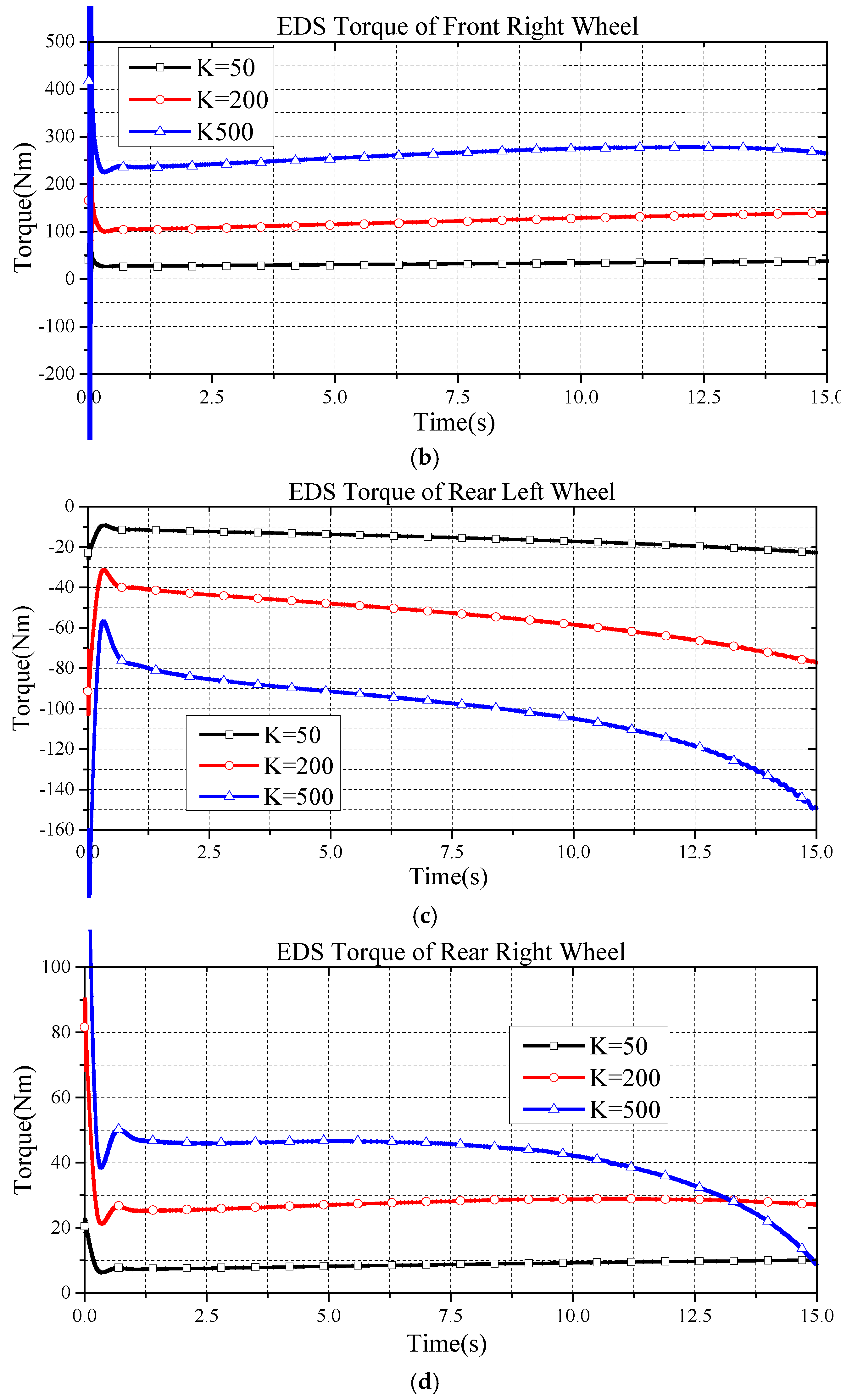
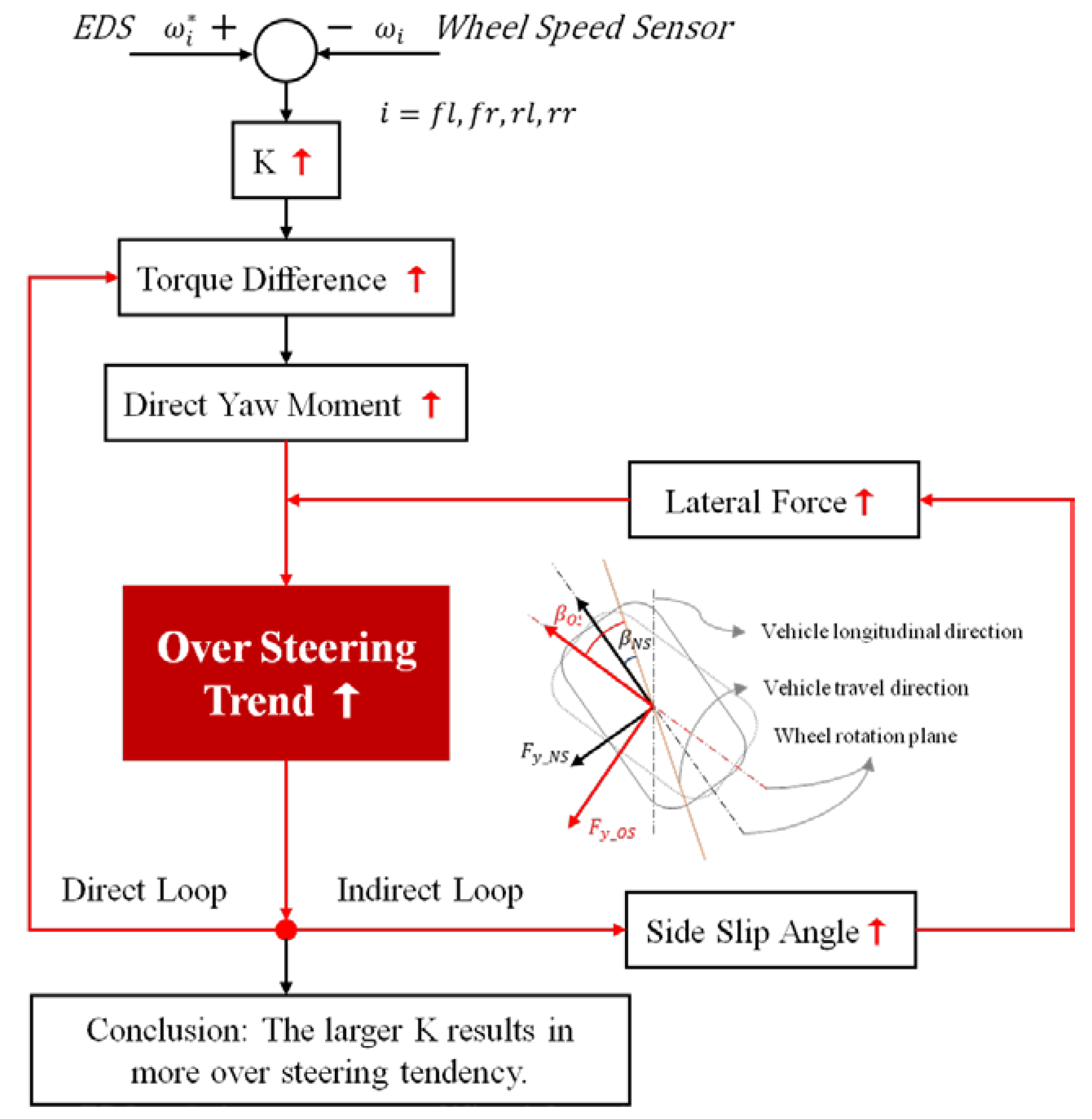
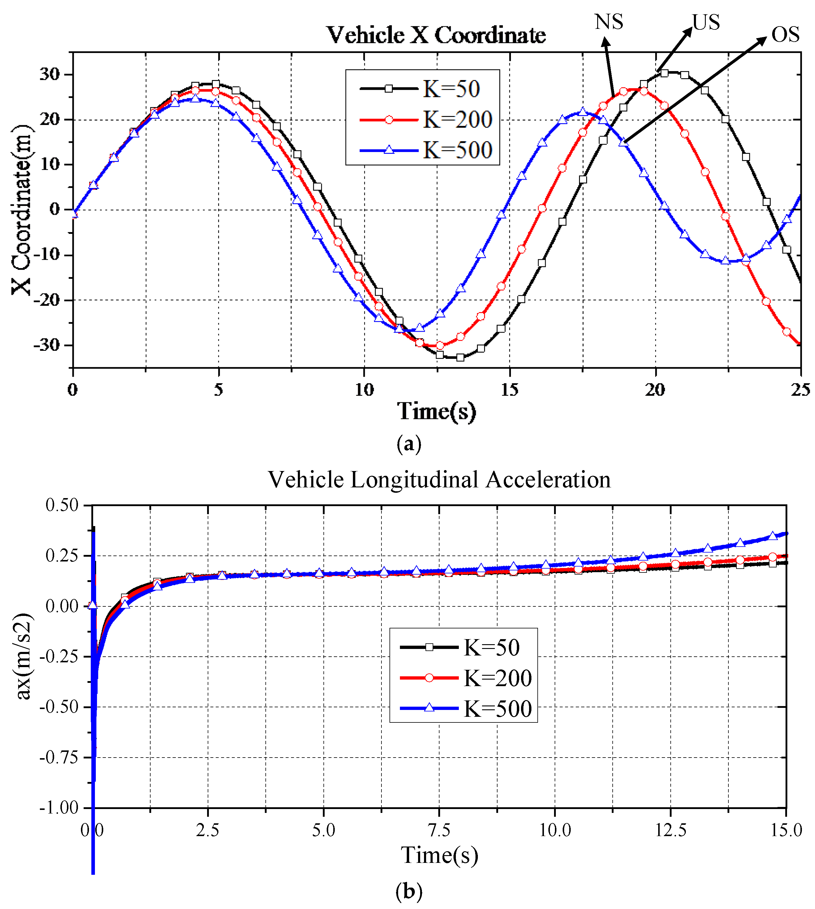
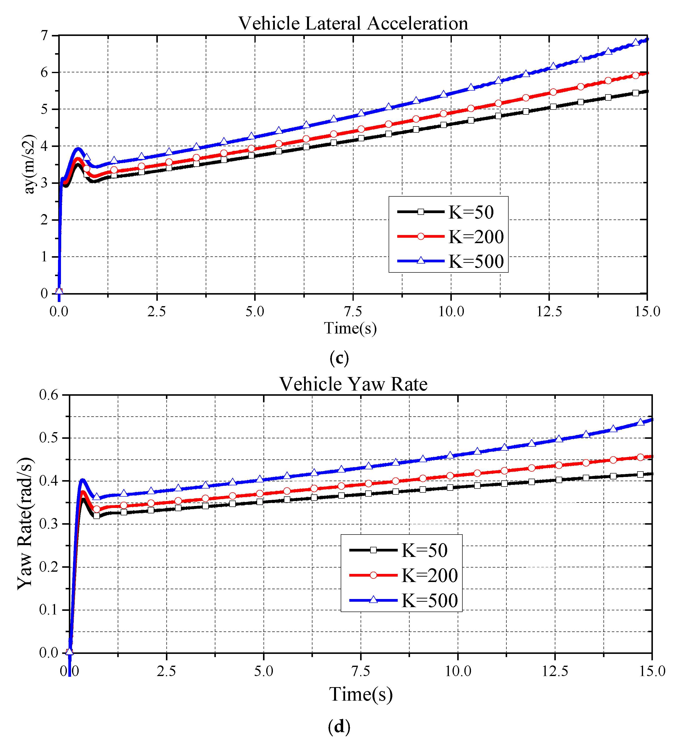
4. Simulations and Discussion
5. Conclusions
Acknowledgments
Author Contributions
Conflicts of Interest
References
- Tabbache, B.; Kheloui, A.; Benbouzid, M.E.H. An adaptive electric differential for electric vehicles motion stabilization. IEEE Trans. Veh. Technol. 2011, 60, 104–110. [Google Scholar] [CrossRef] [Green Version]
- Zhao, Y.E.; Zhang, J.W. Modelling and simulation of electronic differential system for an electric vehicle with two-motor-wheel drive. Int. J. Veh. Syst. Model. Test. 2009, 4, 117–131. [Google Scholar] [CrossRef]
- Hartani, K.; Bourahla, M.; Miloud, Y.; Sekkour, M. Direct torque control of an electronic differential for electric vehicle with separate wheel drives. J. Autom. Syst. Eng. 2008, 2, 22–38. [Google Scholar]
- Tsai, M.C.; Hu, J.S. Pilot control of an auto-balancing two-wheeled cart. Adv. Robot. 2007, 21, 817–827. [Google Scholar] [CrossRef]
- Hu, J.-S.; Lin, X.-C.; Yin, D.; Hu, F.-R. Dynamic motion stabilization for front-wheel drive in-wheel motor electric vehicles. Adv. Mech. Eng. 2015, 7, 1–11. [Google Scholar] [CrossRef]
- Nasri, A.; Gasbaoui, B.; Fayssal, B.M. Sliding mode control for four wheels electric vehicle drive. Procedia Technol. 2016, 22, 518–526. [Google Scholar] [CrossRef]
- Ren, T.-J.; Chen, T.-C.; Chen, C.-J. Motion control for a two-wheeled vehicle using a self-tuning PID controller. Control Eng. Pract. 2008, 16, 365–375. [Google Scholar] [CrossRef]
- Shimizu, H.; Harada, J.; Bland, C.; Kawakami, K.; Chan, L. Advanced concepts in electric vehicle design. IEEE Trans. Ind. Electron. 1997, 44, 14–18. [Google Scholar] [CrossRef]
- Hori, Y. Future vehicle driven by electricity and control-research on four-wheel-motored “UOT electric march II”. IEEE Trans. Ind. Electron. 2004, 51, 954–962. [Google Scholar] [CrossRef]
- Hu, J.S.; Huang, Y.R.; Hu, F.R. Development of traction control for front-wheel drive in-wheel motor electric vehicles. Int. J. Electr. Hybrid Veh. 2012, 4, 344–358. [Google Scholar] [CrossRef]
- ISO 4138:2012. In Passenger Cars—Steady-State Circular Driving Behaviour—Open-Loop Test Methods; International Organization for Standardization: Geneva, Switzerland, 2012.
- Kahveci, H.; Okumus, H.I.; Ekici, M. An electronic differential system using fuzzy logic speed controlled in-wheel brushless DC motors. In Proceedings of the 2013 Fourth International Conference on Power Engineering, Energy and Electrical Drives, Istanbul, Turkey, 13–17 May 2013.
- Gair, S.; Cruden, A.; McDonald, J.; Hredzak, B. Electronic differential with sliding mode controller for a direct wheel drive electric vehicle. In Proceedings of the 2004 IEEE International Conference on Mechatronics, Istanbul, Turkey, 3–5 June 2004.
- Yıldırım, M.; Öksüztepe, E.; Tanyeri, B.; Kürüm, H. Design of electronic differential system for an electric vehicle with in-wheel motor. In Proceedings of the 2016 IEEE Power and Energy Conference at Illinois (PECI), Urbana, IL, USA, 19–20 February 2016.
- Zhou, Y.; Li, S.; Zhou, X.; Fang, Z. The control strategy of electronic differential for EV with four in-wheel motors. In Proceedings of the 2010 Chinese Control and Decision Conference, Xuzhou, China, 26–28 May 2010.
- Hajihosseinlu, A.; Filizadeh, S.; Bistyak, G.; Dirks, E. Electronic differential design for a vehicle with four independently controlled in-wheel motors. In Proceedings of the 2014 IEEE International on Electric Vehicle Conference (IEVC), Florence, Italy, 17–19 December 2014.
- Zhao, L.; Liu, Z. Vehicle velocity and roll angle estimation with road and friction adaptation for four-wheel independent drive electric vehicle. Math. Probl. Eng. 2014, 2014. [Google Scholar] [CrossRef]
- Alipour, H.; Sabahi, M.; Sharifian, M.B.B. Lateral stabilization of a four wheel independent drive electric vehicle on slippery roads. Mechatronics 2015, 30, 275–285. [Google Scholar] [CrossRef]


| Sprung Mass | 1527 kg |
|---|---|
| Unsprung mass | 182 kg |
| Width D | 1535 mm |
| Height of center of gravity | 540 mm |
| Wheelbase L | 2690 mm |
| Unloaded wheel radius | 394 mm |
© 2017 by the authors; licensee MDPI, Basel, Switzerland. This article is an open access article distributed under the terms and conditions of the Creative Commons Attribution (CC-BY) license (http://creativecommons.org/licenses/by/4.0/).
Share and Cite
Yin, D.; Shan, D.; Hu, J.-S. A Study on the Control Performance of Electronic Differential System for Four-Wheel Drive Electric Vehicles. Appl. Sci. 2017, 7, 74. https://doi.org/10.3390/app7010074
Yin D, Shan D, Hu J-S. A Study on the Control Performance of Electronic Differential System for Four-Wheel Drive Electric Vehicles. Applied Sciences. 2017; 7(1):74. https://doi.org/10.3390/app7010074
Chicago/Turabian StyleYin, Dejun, Danfeng Shan, and Jia-Sheng Hu. 2017. "A Study on the Control Performance of Electronic Differential System for Four-Wheel Drive Electric Vehicles" Applied Sciences 7, no. 1: 74. https://doi.org/10.3390/app7010074