A Comparative Exergoeconomic Evaluation of the Synthesis Routes for Methanol Production from Natural Gas


1
Department of Energy Engineering, Zentralinstitut El Gouna, Technische Universität Berlin, 13355 Berlin, Germany
2
Institute for Energy Engineering, Technische Universität Berlin, 10587 Berlin, Germany
*
Author to whom correspondence should be addressed.
Appl. Sci. 2017, 7(12), 1213; https://doi.org/10.3390/app7121213
Submission received: 30 October 2017
/
Accepted: 20 November 2017
/
Published: 24 November 2017
(This article belongs to the Section Energy Science and Technology)
Abstract
:Methanol is one of the most important feedstocks for the chemical, petrochemical, and energy industries. Abundant and widely distributed resources as well as a relative low price level make natural gas the predominant feedstock for methanol production. Indirect synthesis routes via reforming of methane suppress production from bio resources and other renewable alternatives. However, the conventional technology for the conversion of natural gas to methanol is energy intensive and costly in investment and operation. Three design cases with different reforming technologies in conjunction with an isothermal methanol reactor are investigated. Case I is equipped with steam methane reforming for a capacity of 2200 metric tons per day (MTPD). For a higher production capacity, a serial combination of steam reforming and autothermal reforming is used in Case II, while Case III deals with a parallel configuration of CO2 and steam reforming. A sensitivity analysis shows that the syngas composition significantly affects the thermodynamic performance of the plant. The design cases have exergetic efficiencies of 28.2%, 55.6% and 41.0%, respectively. The plants for higher capacity can produce at a competitive price, while the design in Case I is hardly economically feasible. An exergoeconomic analysis reveals a high cost impact of the reforming unit, air and syngas compressors.
1. Introduction
Methanol is rated among the most important feedstocks for the chemical, petrochemical and energy industries, with a worldwide production of 83 million metric tons in 2015. The global production is forecasted to grow annually by an average rate of 7.2% to reach 117 million metric tons in 2020 [1]. The industrial applications range from the further processing to bulk chemicals, e.g., formaldehyde and acetic acid, to the production of synthetic fuels, including methyl-tert-butylether (MTBE) and dimethylether (DME). The increasing demand will particularly be driven by energy applications, which today already account for 40% of the methanol consumption [2]. Applications in the energy sector mainly include refined product displacement, in the form of methanol to olefins (MTO) and gasoline blends [1,2].
Methanol can be synthesized from any hydrocarbon source, including renewable and fossil resources, via direct and indirect conversion processes. Direct synthesis processes (e.g., the direct selective oxidative transformation of methane) have the major advantage of avoiding the energy intensive step of syngas production, but are technically difficult to accomplish. The main disadvantages refer to a low conversion of the feedstock and the production of undesired byproducts, due to the higher reactivity of the oxidation products compared to methane [3].
Although direct processes are getting more into the focus of research, industrial methanol is exclusively produced by indirect conversion routes via syngas production. Since synthesis gas routes are capital intensive, there is a great interest in optimizing the process concepts. Due to abundant resources, a low-price level which is subject to moderate volatilities, and low content of impurities, natural gas is the predominating feedstock for methanol production. In general, a synthesis route comprises a pretreatment of natural gas, a reforming unit for syngas generation, a gas conditioning section, a low-pressure methanol synthesis unit and several distillation columns for product purification. The reforming of natural gas has been investigated thoroughly in the literature and has been commercially applied to the most important branches of chemical industry [4,5]. From an economic point of view, the highest sensitivity of the overall cost of a methanol plant is related to the reforming section, accounting for more than 60% of the capital investment. Catalytic steam reforming of methane (SMR) is the most widely used technology for syngas generation in methanol plants, while the implementation of alternative technologies such as autothermal reforming (ATR), dry methane reforming (DMR) and gas heated reforming (GHR) has started in the last decade. The variety of available reforming technologies differs in construction, in supply of reforming agents and in operation conditions. Accordingly, the reaction turnover and the syngas composition vary significantly. Therefore, the choice of a reformer option decisively determines the plant design. The consideration of alternative reforming technologies resulted from the ever-rising single train capacities and the economies of scale. The capacity of new plant constructions increased from 2.500 MTPD a decade ago to about 5.000 MTPD today [6,7]. The SMR technology is typically applied to plants with a maximum capacity of 2.500 MTPD, while oxygen-based technologies (and combinations of ATR and SMR) cover the range above. The capacity demarcation is caused by the economies of scale being different for the tubular reformer and the oxygen plant that is required for the supply of gaseous oxygen (GOX) to the ATR [8]. Operation parameters and syngas production concepts incorporating SMR technology have been investigated intensively in [9,10]. Data on parameters and consumption for two-step reforming concepts (SMR + oxygen blown secondary reformer) and ATR are reported in [7,8]. Dry Methane Reforming by CO2 (DMR) is a new technology that has been first implemented on an industrial scale in a methanol plant in Shriaz (Iran) in the year 2002 [11]. The chemistry and thermodynamics of DMR have been analyzed in [12,13], while Baltrusaitis et al. investigated the economics of integrated syngas production concepts for DMR [14]. Noureldin et al. [15] examined the carbon fixation potential of DMR in combination with other reforming technologies and reported an inverse relationship between CO2 fixation and an optimal composition for liquid fuel synthesis. Luyben [16] studied a parallel DMR and SMR process and analyzed the thermodynamics and the potential for Fischer-Tropsch syngas generation. A techno-economic analysis on a similar process design was conducted by Zhang et al. [17]. They reported an economic feasibility for a capacity range of 2500–5000 MTPD. Machado et al. [18] compared a conventional production process from syngas with a pure hydrogenation of CO2 for methanol synthesis. They studied the operation conditions and set up a comparison in terms of energy consumption and CO2 emissions. Luu et al. [19] investigated six different scenarios of syngas production from four integrated methane reforming technologies. The comparison revealed significant differences based on methane and energy intensity. The authors of [20] conducted an exergy analysis on a commercially available low-pressure synthesis process based on SMR and reported an exergetic efficiency of 39%.
This paper analyzes three cases for indirect process routes for the production of methanol from natural gas. The base case (Case I) includes a conventional synthesis route based on SMR in combination with an isothermal synthesis reactor for a production capacity of 2.200 MTPD. To meet a greater capacity range of around 4.700 MTPD, a combination of SMR and ATR is used in conjunction with an isothermal reactor (Case II). Case III refers to syngas production by SMR and DMR for a similar production capacity. Rigorous simulations are performed on commercially available process units implemented in new plant concepts for optimal synthesis routes. Sensitivity analyses are conducted to investigate the chemistry and the thermodynamics of the most important equipment. Subsequently, the three scenarios are subject to an exergetic and an economic analysis before an exergoeconomic analysis identifies the components with the highest cost impact. Furthermore, design (structure) and parametric optimization are discussed.
2. State of the Art
The commercial routes for the production of methanol via indirect processes include a cleaning unit for the pretreatment of natural gas (sub-system I), before the conversion to syngas takes place in a reforming unit (sub-system II). Various processes for the production of syngas from natural gas exist, whereby the main technologies are covered within this work.
Depending on the reforming technology, the syngas has a typical composition deviating from the stoichiometric composition required by the synthesis unit (Table 1). Therefore, for an adjustment of the composition, several syngas conditioning and reforming technologies are used and combined. The syngas in methanol synthesis should have a balanced composition of CO, CO2, and H2, which is expressed by several stoichiometric measures. There is still a disagreement about the ideal composition of a syngas in methanol applications, since the reaction mechanism over CO and CO2 in reactions (2) and (3) has not yet definitely been clarified. Several studies characterize the composition simply by using the H2/CO ratio, which equals 2 in the ideal case. In this approach, the hydrogenation of CO2 via reaction (3) in the stoichiometric consideration is neglected. Although the methanol synthesis is assumed to proceed mainly over CO, the reaction is 100 times faster in the presence of CO2 [21]. Taking into account the role of CO2, a second parameter referred to as stoichiometric module (S module)
is proposed to describe the stoichiometry of both reactions. With respect to commercially used copper-based catalysts, the module ideally has a value of slightly above 2 [22]. Typically, the feed gas composition for methanol synthesis is adjusted to contain 4–8% CO2 for maximum activity and selectivity [23]. Commercially used catalysts show a high reactivity in reaction (4), whereby CO is involved in the water-gas shift reaction (WGS). Therefore Dybkjaer et al. [24] counter, that the stoichiometric module is not adequate to reflect the reactivity of a syngas, since the measure is independent of the WGS reaction. Instead they suggest using the CO/CO2 ratio for this purpose, whereby the conversion rate increases with the ratio.
S = (H2 − CO2)/(CO + CO2)
CO2 + 3H2 → H2O + CH3OH (−49.7 kJ/mol)
CO + 2H2 → CH3OH (−90.7 kJ/mol)
CO + H2O → CO2 + H2 (41.0 kJ/mol)
The effluent from the syngas conditioning unit is compressed in a multistage reactor system to overcome the difference in operating pressure between the reforming unit and the methanol synthesis (sub-system III). The synthesis reactors are based on two major technologies: Direct cooled reactors which are designed as multi-tube reactors and adiabatic fixed-bed reactors with quench gas cooling. Low product yields require a recycle of unreacted syngas to the reactor inlet: A purge is used to keep the inert gas content at a suitable level. The crude methanol is degassed by flash and fed to a multi distillation column system (sub-system IV).
In the following the major process equipment is investigated to enable an understanding of the synthesis routes of the three analyzed cases. The final scenarios are described in detail in Section 4.
2.1. Reforming Technologies
Several reforming technologies are applied for syngas generation from natural gas: Steam methane reforming, autothermal reforming and dry methane reforming. Regarding the syngas production, steam methane reforming (SMR) is a proven and the most widely applied technology. In SMR, methane reacts in a highly endothermic reaction with steam over a catalyst, typically based on nickel, at temperatures between 800–1000 °C and pressures in the range of 20–30 bar [4,25,27].
The strongly endothermic reaction mechanism is associated with a high heat duty, which is supplied through the combustion of fuel or unreacted syngas from the synthesis unit in a reformer furnace. The large steam requirement at steam to carbon ratios above 3.5 results in large mass flows downstream the reforming unit. In consequence, the size and capital expenditures (CAPEX) for the components in the synthesis and distillation unit are high compared to process routes with alternative reforming technologies. Moreover, the supply of additional fuel to the reformer furnace and the high electricity consumption for compression units in the synthesis loop cause high operation costs (OPEX). The upscaling of SMR-based methanol production is only economically justifiable in a single train capacity of up to 2500 MTPD. Above this capacity, other reforming technologies become beneficial, since the economies of scale effect has a stronger impact on their cost reduction [8]. For a capacity range of 2500 to 5000 MTPD, a two-step reforming including a primary steam reformer followed by an oxygen-blown secondary reformer is the preferred concept. The use of oxygen reduces the steam to carbon ratio in the primary reformer, but additionally requires an air separation unit (ASU). Above a capacity of 5000 MTPD, ATR is the only appropriate technology, as higher cost reductions associated with the upscaling are achieved with an ASU than with tubular reforming.
An ATR reactor has a compact design, accommodating a combustion chamber and a catalytic fixed bed, located in a refractory lined vessel. Oxygen or oxygen enriched air is deployed together with steam to partially oxidize the methane intake according to reactions in Table 1. The partial oxidation of methane is highly exothermic and results in high operation temperatures between 950–1400 °C (Table 1). To keep the temperature in a moderate range and to allow for adequate hydrogen content, steam is fed to the inlet to initiate the endothermic SMR in reaction given in Table 1. Asteam-to-carbon ratio (S/C-ratio) of 0.5–1.5 and an oxygen-to-carbon ration (O/C-ratio) in the range 0.6–1.0 have been reported by different manufacturers. The composition of the syngas produced by ATR has a typical S module in the range of 1–2 and a CO/CO2-ratio of 2.5–5.5 [5,28,29]. Furthermore, high conversion of methane is favored in a high-pressure range of 30–50 bar, which is advantageous in terms of syngas compression. In comparison to SMR, the use of an ATR reduces the steam requirement and therefore results in lower mass flow rates and smaller equipment size of the downstream components. Additionally, the heat of reaction can be integrated to cover the heat requirement of the pre-heating unit and other heat consumers. With respect to the synthesis of methanol, ATR as a stand-alone reforming technology cannot fulfill the stoichiometric requirement. Typically, the syngas composition is characterized by a hydrogen deficiency, which results in a lower per pass conversion in the methanol reactor.
The dry methane reforming technology (DMR) is the third option of syngas production, which is analyzed in the present work. DMR is a relatively new technology that is considered as a promising carbon utilization concept [18,19]. According to the reaction in Table 1, methane reacts with carbon dioxide over a nitrogen based catalyst to give hydrogen and carbon monoxide at a ratio of one. Activation of the endothermic reaction requires a radiant furnace or convective heat input for a Gas Heated Reformer (GHR). A thermodynamic analysis shows that the reaction is favored at temperatures above 900 °C and pressures in the range of 5–10 bar to attain high syngas yields. High temperatures also reduce the deposition of carbon on the catalyst surface, which inevitably accompanies the DMR reaction [12].
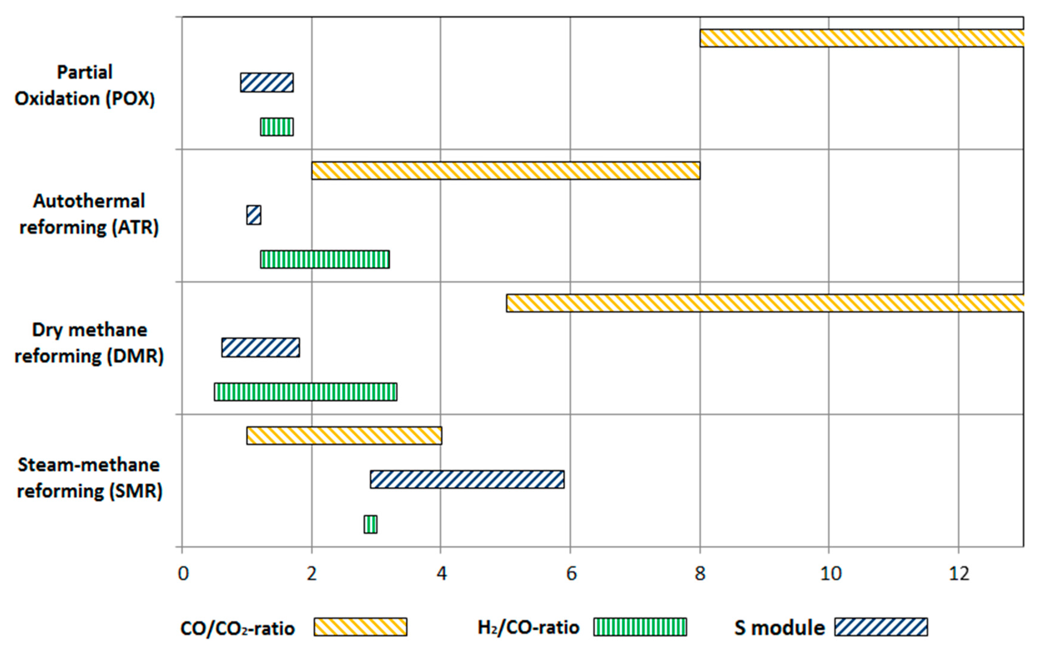
The bar chart in Figure 1 shows the typical range of the stoichiometric measure for the most common syngas production technologies (from methane). The data have been recorded for the typical operation parameters described above. The syngas from POX, ATR and DMR is highly reactive due to the high CO/CO2-ratio, but is deficient in hydrogen. Vice versa, the syngas from SMR is characterized by excess hydrogen and lower reactivity. The deviation of the S module from the ideal value of (S~2.05) means losses in terms of methanol yield and causes avoidable costs in the synthesis unit. The sensitivity analysis shows that a stand-alone reforming technology is not suitable for methanol synthesis.
The conventionally fired reformer technology has a contribution of above 60% to the overall cost of a methanol plant. A future alternative reactor, the gas heated reformer (GHR), is associated with potential cost savings and efficiency improvements. In principle, a gas-heated reformer has the same characteristics as a conventional tubular fired reformer, whereby the heat is convectively transferred from a hot flue gas (or steam) to the process gas. The once-through tubes of a SMR are substituted by bayonet tubes in the GHR design, so that the catalyst bed is heated from by flue gas and product gas from outside and inside, respectively. In this work, the SMR unit in Cases II and III as well as the DMR reactor in Case III are designed as a gas heated reactor. Further details on the design and thermodynamics can be obtained from [30].
2.2. Methanol Synthesis
In the synthesis step, carbon monoxide and carbon dioxide react with hydrogen according to the exothermic reactions (2) and (3). Additionally, both reactants are involved in the water gas shift reaction (4), which strongly influences the reaction mechanism.
The generation of methanol is limited by chemical equilibrium and favored at low temperatures and pressures. However, in order to obtain significant reaction rates, the synthesis is conducted in the presence of a Ni/Zn/Al2O3 catalyst at temperatures between 200–300 °C and pressures between 50–100 bar, resulting in a yield of 5–14 mole-% methanol at the outlet [3,5,23,28]. The crude product can be easily separated from the unreacted syngas through flashing near ambient temperature. The unreacted syngas is recycled to the inlet of the reactor and combined with fresh make-up gas. As the synthesis gas contains impurities in the form of inert gases (methane, butane, propane), a small fraction has to be purged from the loop. These features together with the metallurgical restrictions and the catalyst properties determine the methanol synthesis reactor design and the configuration of the synthesis loop.
With respect to this study an indirect-cooled pseudo-isothermal reactor [29,30,31] and a direct-cooled adiabatic quench reactor are investigated [32]. The synthesis concepts mainly differ in heat integration, make-up gas introduction and removal of impurities. The isothermal reactor is modeled according to the worldwide commercially used Lurgi Steam Raising Reactor, which is based on a tube shell design. On the shell side, the released heat of reaction is raised as medium-pressure steam, which is typically used in the reboilers of the distillation columns or for driving the syngas compressors. Regarding the second concept, a multistage fixed bed reactor was chosen according to the design of Imperial Chemical Industries’ (ICI) reactor. The quench design is the dominating technology for methanol production with a market share of 70%. It consists of up to five fixed catalyst beds which are separated in one reactor vessel. A part of the circulating gas is mixed with fresh, cold syngas and fed to the inlet of the reactor. The remainder is injected as a quench gas between the catalyst beds to ensure an efficient reactor cooling.
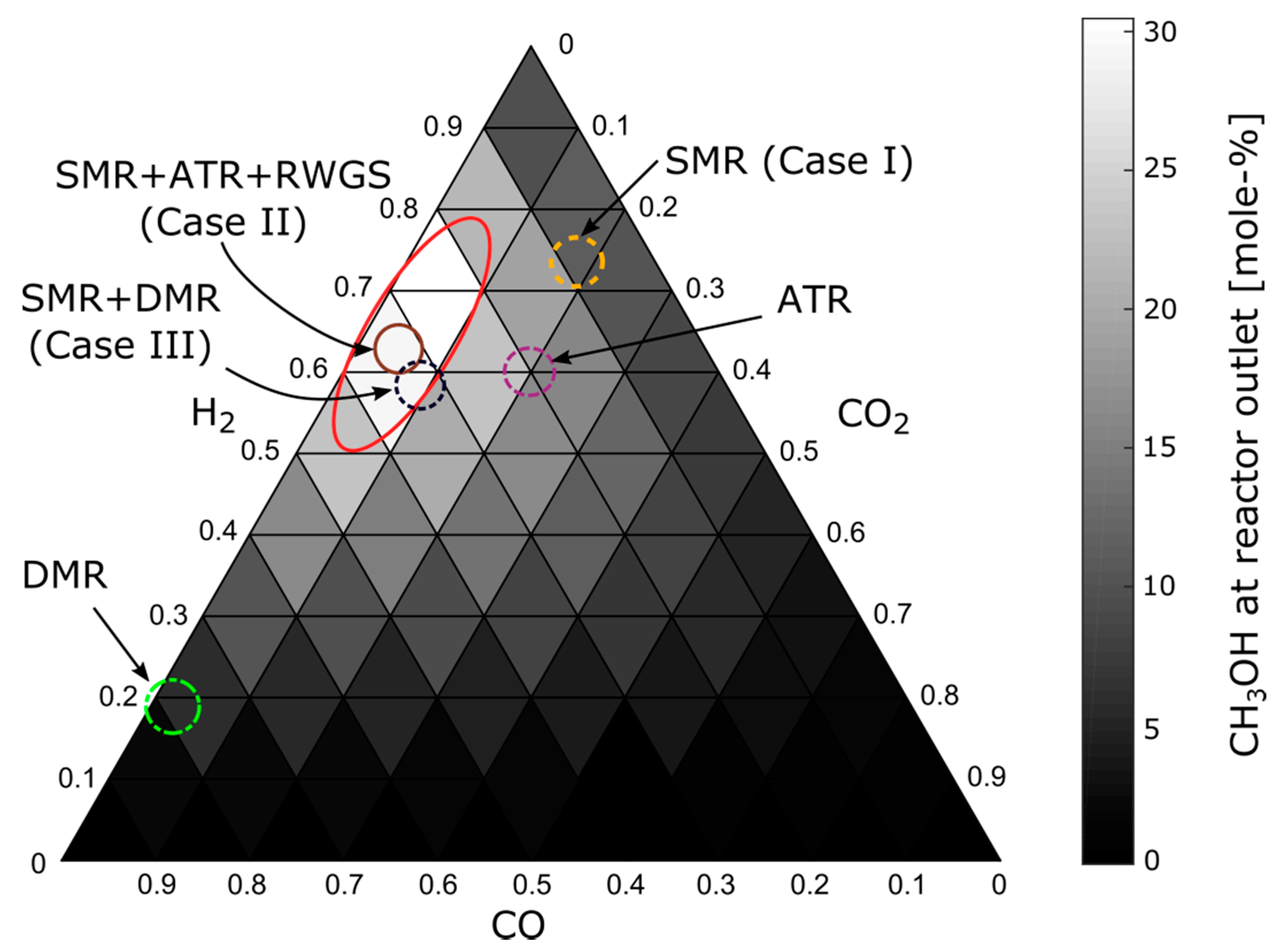
The sensitivity of the methanol fraction at the reactor outlet to the inlet composition is shown in the ternary composition diagram in Figure 2 for equilibrium conditions of 50 bar and 250 °C. The area of optimal syngas composition for maximum methanol production is identified by the elongated ellipse. The results of the sensitivity analysis correspond to the stoichiometric measures given above. Furthermore, the syngas compositions for three basic reforming technologies (SMR, ATR and DMR) and the three analyzed cases are highlighted. Both reactor models were integrated under three different scenarios of syngas generation. Due to kinetic limitations, the real methanol fraction at the outlet is far below equilibrium yield. Regarding Lurgi’s isothermal reactor, the methanol outlet fraction was 6.9 mole-%, 10.5 mole-%, and 9.4 mole-% for Cases I, II, and III, respectively.
A four-bed quench reactor based on [32] is integrated in the Cases I, II, and III in Figure 2. The distribution of the inlet gas and quench gas is subject to an optimization to maximize the methanol yield at the reactor outlet. The simulation results show that the methanol mole fraction in the effluent is in a low range of 4–5 mole-% for all cases. This led to the exclusion of the quench reactor for further investigations.
3. Methodology and Assumptions
For an analysis and evaluation of energy conversion systems, exergy analysis is a convenient and powerful tool. The identification of thermodynamic inefficiencies within a process design, allows deriving measures for subsequent design improvements. Furthermore, an economic analysis is conducted to estimate the major costs involved in each scenario. The combination of both methods in an exergoeconomic analysis is the basis for future design improvement.
With respect to the simulation in Aspen Plus V9 (Aspen Technology, Inc., Burlington, MA, USA, 2017), the major assumptions used for the three design cases are presented in Table 2. The thermodynamic properties are calculated by employing the Redlich-Kwong-Soave equation of state for all units of the process. Several kinetic models are implemented into the reactors to analyze the thermodynamics of the reaction sets. Regarding the methanol synthesis, the reaction kinetic inputs to the RPLUG model are based on a study by van den Bussche et al. [33], in which a Cu/ZnO/Al2O3 catalyst is used for methanol conversion. The kinetics is described by the Langmuir-Hishlewood-Hougon-Watson (LHHW) model and the parameters are taken from Luyben et al. [34]. Furthmore, Powerlaw kinetics based on [16] are used for the SMR and the DMR unit. The combustion reactions in the ATR are assumed to reach equilibrium.
3.1. Exergy Analysis
An exergy analysis can be applied to investigate the real thermodynamic inefficiencies, which are not accessible through a conventional energy analysis. The methodology is well established and has been applied to thermal energy conversion systems as well as to chemical processes [36]. Ambient conditions are assumed to be 15 °C and 1.013 bar, using the model of Szargut [37] for the determination of the specific chemical exergy of a j-th stream. Taking into account steady-state conditions, the exergy destruction rate within the k-th component is calculated as the difference between the exergy rate of fuel and exergy rate of product
The exergy rates of fuel and product for different components are defined according to the SPECO approach [38]. Hereby, the exergy destruction rate quantifies the thermodynamic irreversibilities within the k-th component. Applying the exergy rate definitions, the exergetic efficiency for the k-th component can be calculated as
The exergetic efficiency is a unique indicator which allows for a characterization of a system’s component in terms of performance and comparability. Another important parameter is the exergy destruction ratio, identifying the contribution of a single component to the reduction in exergetic efficiency of the overall system.
The exergy analysis provides information which is not available by a conventional thermodynamic analysis, identifies the main sources of thermodynamic inefficiencies, and develops first suggestions of possible improvements. However, a thermodynamic improvement which aims at minimizing the thermodynamic inefficiencies only represents a subcase of the general case of design improvement. Additionally, an economic analysis is required to consider the total investment cost in the design improvement. Finally, an exergoeconomic analysis serves to assign monetary values to the thermodynamic inefficiencies, occurring within the system components.
3.2. Economic Analysis
The completion of a chemical plant design requires estimation of the major costs involved in the project. The total revenue requirement (TRR) method is applied to identify the costs associated with total capital investment, the fuel, operation and maintenance, and with the final products. According to the approach described in [36], the fixed-capital investment (FCI) is calculated as the sum of direct and indirect cost.
The direct costs include the sum of onsite costs and offsite costs. Onsite costs include the purchased equipment cost (PEC), cost of installation, piping, instrumentation and control as well as cost for electrical equipment and materials. The PEC for pumps, heat exchangers, compressors, and expanders is based on data from [39,40,41], whereas in the cost calculations of the distillation columns also data from [42,43,44,45] were used. Cost estimations for the SMR, ATR and DMR units were obtained from [39,40,45]. The modular method is applied along with an appropriate determination of a bare-module factor for the calculation of the onsite costs of each piece of equipment [40]. All data are brought to a common reference year (2016) by using the corresponding Chemical Engineering Cost Indexes (CEPCI).
Regarding the offsite costs, civil, structural and architectural work is considered to be 30% of the total PEC, while contingencies amount to 15% of PEC. Other outlays include allowance for funds during construction, which are subject to an effective interest rate of 8% and a general inflation rate of 2.5%. After starting the construction in 2013, 40% of the FCI was invested in mid-year 2014 and the rest in mid-year 2015. The summation of the FCI and the other outlays gives the total capital investment (TCI). The operation of the plants started in 2016 and the economic life-time is assumed to be 20 years. The plants are operated with 8000 full load hours a year. The average price for natural gas was determined based on the Henry Hub natural gas spot price and is 2.9 US$/GJ. Regarding Case II, the costs for gaseous oxygen (GOX) were obtained from [46]. The fuel price is assumed to escalate by a rate of 1% annually.
3.3. Exergoeconomic Analysis
An exergoeconomic analysis combines the results of an exergetic- and an economic analysis and provides information that is not accessible through conventional analyses, but essential for the design a cost-effective system. The objective of an exergoeconomic analysis is to identify the cost associated with each inefficiency, and the relative cost importance of each component within the system. This is achieved by applying the exergy-costing principle, where a specific monetary value c is assigned to each stream of a plant. The product of the average cost and the total exergy rate results in the cost rate that is assigned to stream . For the exergoeconomic analysis, cost balances need to be developed for each component resulting in a set of balance equations. The cost balance for component is expressed by
The term represents the sum of the cost rates associated with the n streams entering the component, while refers to the sum of the cost rates of the leaving streams. The variable consists of the sum of the cost rates associated with capital investment (CI) and operation and maintenance (O and M). When the number of exiting streams m is higher than one (m > 1), m − 1 auxiliary equations are necessary. The F and P principles are applied to determine the auxiliary equations [38]. An outcome of the analysis is the cost rate associated with the exergy destruction , which is calculated from the specific cost of the fuel for the component () times the corresponding exergy destruction . The exergoeconomic evaluation identifies the components with the highest cost impact which is denoted by the sum of the cost rates associated with exergy destruction and investment (). In addition, the relative cost difference and the exergoeconomic factor are used to evaluate the relative cost increase between and .
The results of the exergoeconomic evaluation facilitate an iterative optimization of the systems and contribute to the improvement of the cost effectiveness of the overall system. By considering the exergoeconomic variables, design changes and changes of the decision variables can be determined to achieve compromises between the investment cost and the cost of exergy destruction in each important component.
4. Case Studies and Process Description
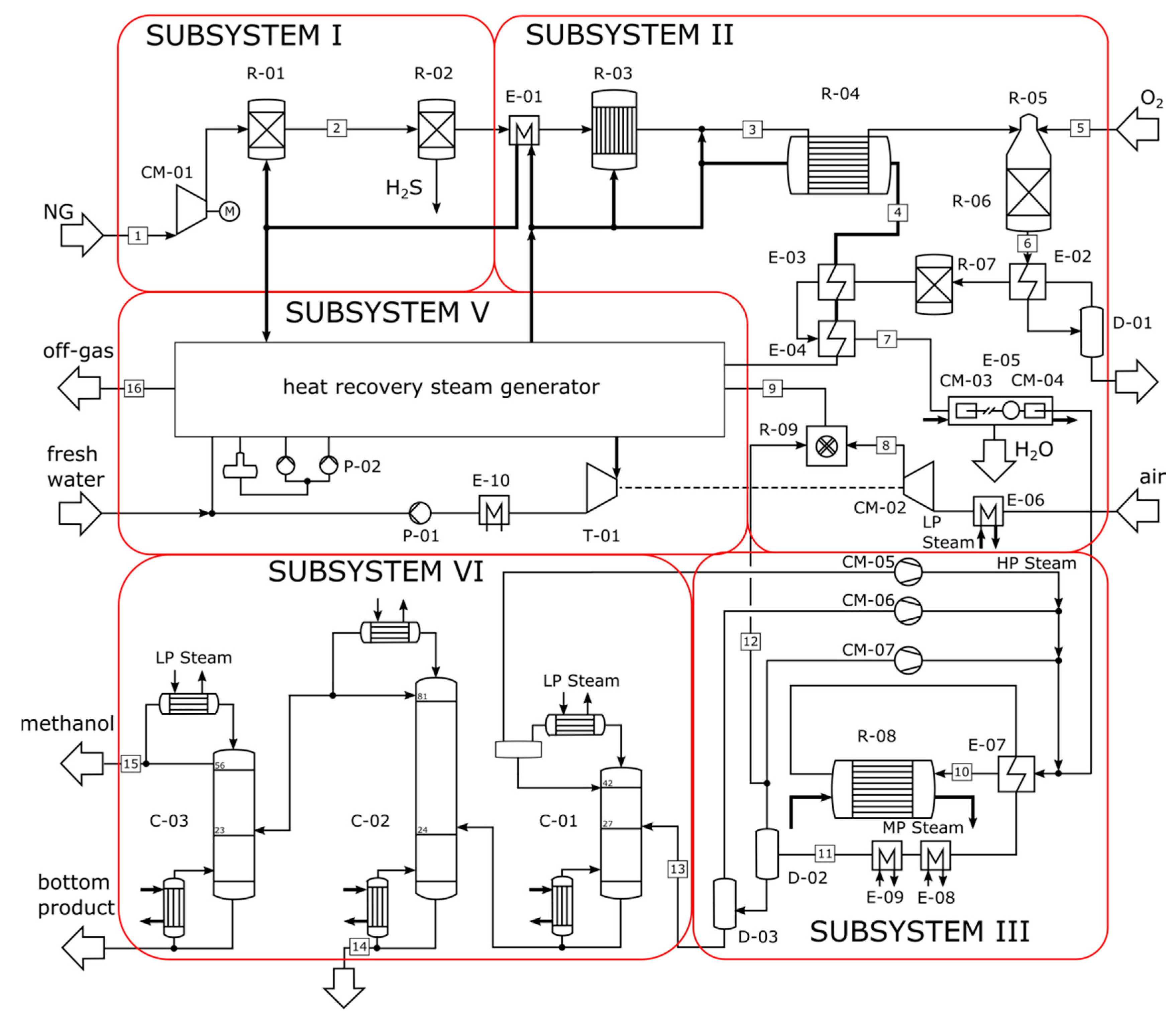
The investigations are carried out for three design cases of commercial methanol production, which mainly differ in terms of the reforming technology (sub-system II), heat integration concept (sub-system V) and total capacity. Common to all designs is a pretreatment unit for desulphurization of natural gas (sub-system I), a methanol synthesis in conjunction with a recycling of unconverted syngas (subsystem III) and the distillation unit for crude product purification (sub-system IV). The three cases refer to
- conventional SMR with low-pressure methanol synthesis for a production capacity of 2200 MTPD,
- a serial two-step configuration of SMR and ATR with low-pressure methanol synthesis for a production capacity of 4750 MTPD, and
- a parallel configuration of SMR and DMR with low-pressure methanol synthesis for a production capacity of 5000 MTPD.
A flow sheet and the corresponding stream data for Cases I, II and III are given in Figure 3, Figure 4 and Figure 5, and in Table 3, Table 4 and Table 5, respectively. The plant designs differ considerably in terms of thermodynamics and economics. The use of different reforming technologies and reforming agents results in a varying effluent composition and mass flow rates from sub-system II. This has implications on the required syngas conditioning technology, the size of the syngas compression unit and on the performance of the methanol synthesis unit. Thus, deviations from the ideal composition signify a lower selectivity and conversion, and consequently higher recycle ratios in the synthesis unit (Figure 2). This affects the size of the compressors negatively and results in increased electricity consumption.
In Case I, water is used at a S/C-ratio of 3.5 to result in a low methane slip of 1 mole-% (stream 6). The tubular SMR takes place at 25 bar and is fired by natural gas in a furnace (R-04). Two large compressors CM-02 and CM-03 feed air to the combustion process. The syngas contains excess hydrogen and has a H2/CO-ratio of 5, which is far above the stoichiometric requirement of the synthesis (S module ~2). For syngas adjustment, the syngas is blended with a CO2 (stream 9). Due to the high CO2 mole fraction, the composition is outside of the ideal composition range (elongated ellipse) in Figure 2, resulting in a low methanol yield of 6.7 mole-%. Accordingly, the recycle-to-feed-ratio (RTFR) has a relatively high value of 7.7. After the synthesis, the process gas passes a flashing unit to separate the liquid crude product from gaseous components (stream 12 and 13). Within the distillation columns, methanol is separated from light ends (butane, propane) and water. A purified stream of 31.3 kg/s methanol is produced according to a methane intensity of 1.86 kgCH3OH/kgCH4.
With respect to Case II, syngas generation is conducted in a serial two-step reforming unit, using steam and oxygen as reforming agents (stream 3 and 5 in Table 4). The heat of the ATR (R-05) is recovered as medium pressure steam, which is provided as a heat source to the tubular SMR (R-04). Thereby, the configuration avoids the need for natural gas as a fuel. Additional heat is provided to the heat recovery steam generator by the combustion of a purge stream (stream 12) in R-07. The integration of the ATR reduces the load and the size of the SMR with a low S/C-ratio of 0.5. The conversion is completed by combustion with 45 kg/s oxygen (stream 15). The resulting syngas composition is in the range of high methanol yield in Figure 2—the H2/CO-ratio is 2.1 and the mole fraction of carbon dioxide is low (stream 6). Downstream, water is rejected in drum D-01 to shift the composition to the product side of WGS reaction and to initiate the reverse water gas shift reaction (RWGS). Accordingly, the small excess of hydrogen reacts with carbon dioxide to increase the carbon monoxide content. The application of a further syngas conditioning unit results in a methanol yield of 10.4 mole-% and an RTFR of 2.13. A stream of 55.1 kg/s methanol is produced corresponding to a methane intensity of 1.23 kgCH3OH/kgCH4.
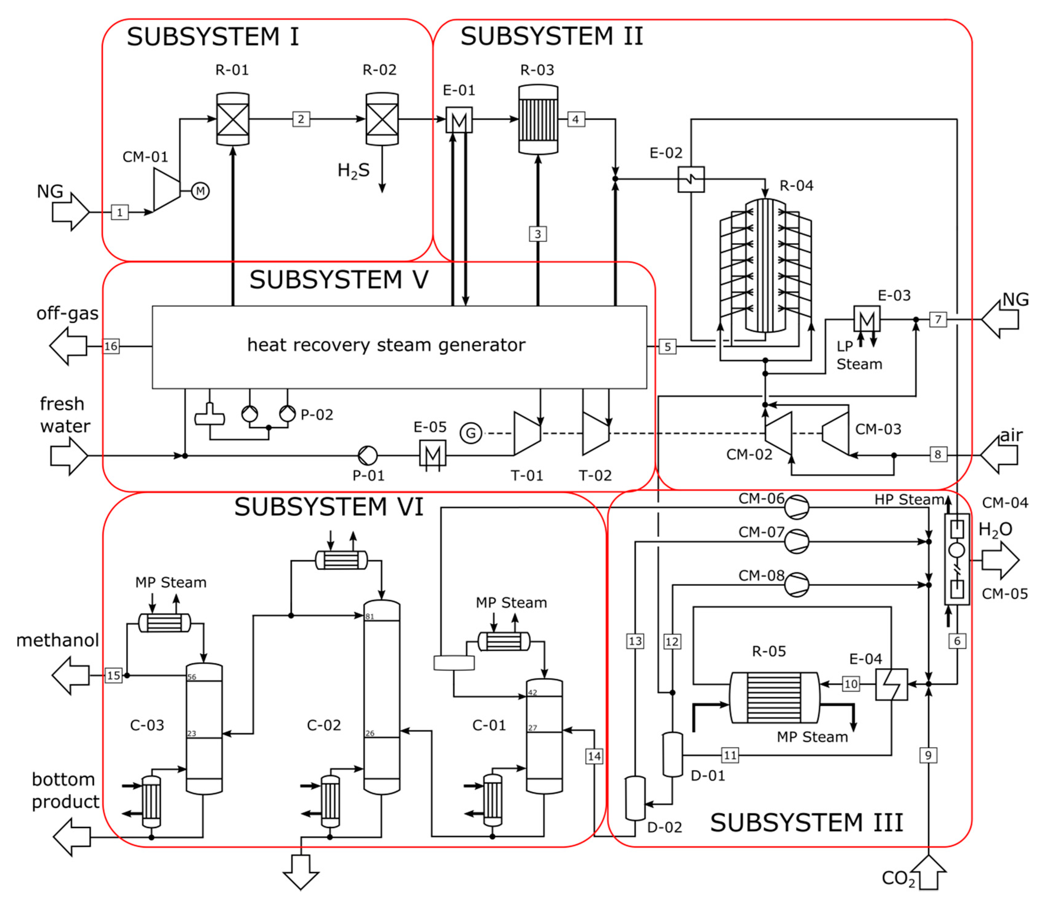
Case III uses the parallel reforming configuration that is shown in the flow sheet in Figure 5. Since the reaction in the DMR (R-04) favors high conversion rates at low pressure, the entire reforming unit needs to be operated at two different pressure levels. This requires the additional compressors CM-01 and CM-02 for the DMR (R-04) and the SMR (R-05) process line.
Both reactors are designed as tubular gas-heated reformers to transfer heat from the combustion gases (stream 9) to the tubes. Due to the high heat demand of the reforming unit, a purge ratio of 0.2 (stream 14 in Table 5) is selected to keep the fuel consumption (stream 8) in a moderate range. However, large, steam-turbine-driven compressors CM-03 and CM-04 are required to feed air to the combustion chamber R-06. A stream of 60 kg/s CO2 is fed as reforming agent to the DMR to result in methane slip below 1 mole-%. The syngas from R-04 contains a high fraction of CO2, which is lowered by blending the product with syngas from the SMR unit. The composition of the synthesis inlet flow (stream 12) is slightly deficient in H2 (H2/CO-ratio = 1.88) and rich in CO2, which reduces the reactivity and the conversion rates of the reactants. The effluent from reactor R-07 contains 9.4 mole-% methanol. The relatively high purge ratio causes a low RTFR of 1.78.
5. Results
5.1. Exergy Analysis
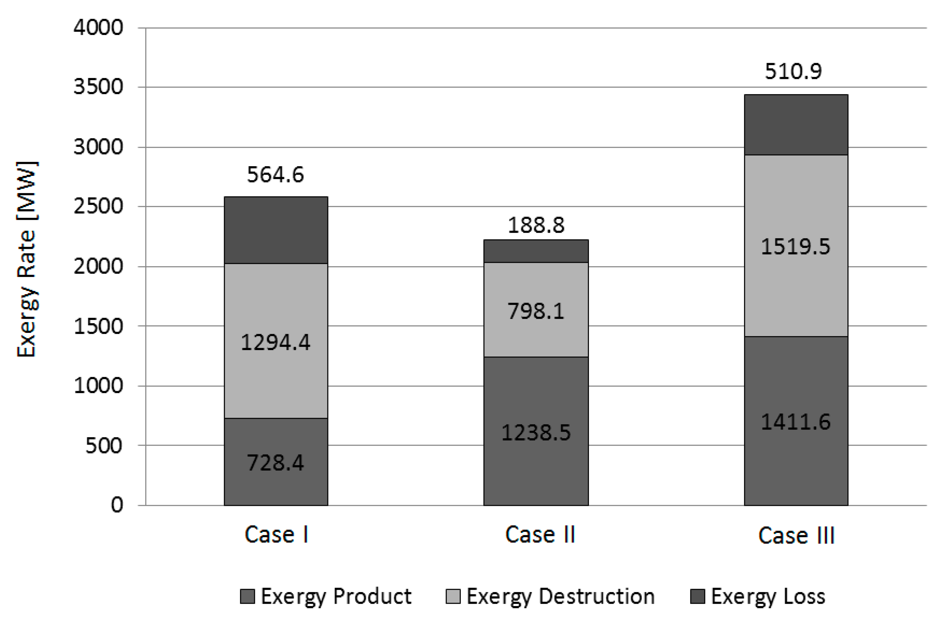
A conventional exergetic analysis is conducted to evaluate the real inefficiencies within the processes. The bar chart in Figure 6 shows a comparison of the results of the exergy analysis for the three design cases.
The process design in Case I has a low exergetic efficiency of 28.15% since only a limited amount of the exergy of fuel (methane as process gas) can be converted to the exergy of product. The major part of the exergy of fuel (methane as fuel) is used to drive the process by providing heat to the SMR unit. Exergy destructions are mainly caused by the combustion process within the SMR furnace and the heat transfer within several heat exchangers.
In Case II all of natural gas and oxygen (exergy of fuel) can be used directly in the process line to produce methanol. Although the production capacity of Case II exceeds that of Case I, less exergy of fuel is required. The energy demand of the SMR unit is satisfied by recovering the heat from partial oxidation in the combustion zone of the ATR. As a consequence, the combustion of the purge gas from the synthesis unit is sufficient to cover the energy demand of the remaining units. The combustion of only a small amount of gas reduces the exergy destruction and eventually also the exergy losses. In summary, the second case is of high thermodynamic performance having an exergetic efficiency of 55.6%.
Case III has the highest production capacity (exergy of product) of all processes. Both, the DMR and SMR are highly endothermic processes, which require the supply of additional exergy of fuel to drive the reactions. To reduce the amount of extra fuel (equal to Case I), a high amount of process gas is purged and recycled to the furnace R-06, causing a reduction in the exergy of product. As in Case I, the exergy losses are mainly assigned to the flue gas leaving the system with stream 16. Most of the exergy destruction occurs within the furnace R-06, the GHR R-04, the DMR R-05 and some heat exchangers in sub-system V. This process design has an exergetic efficiency of 41%.
5.2. Economic Analysis
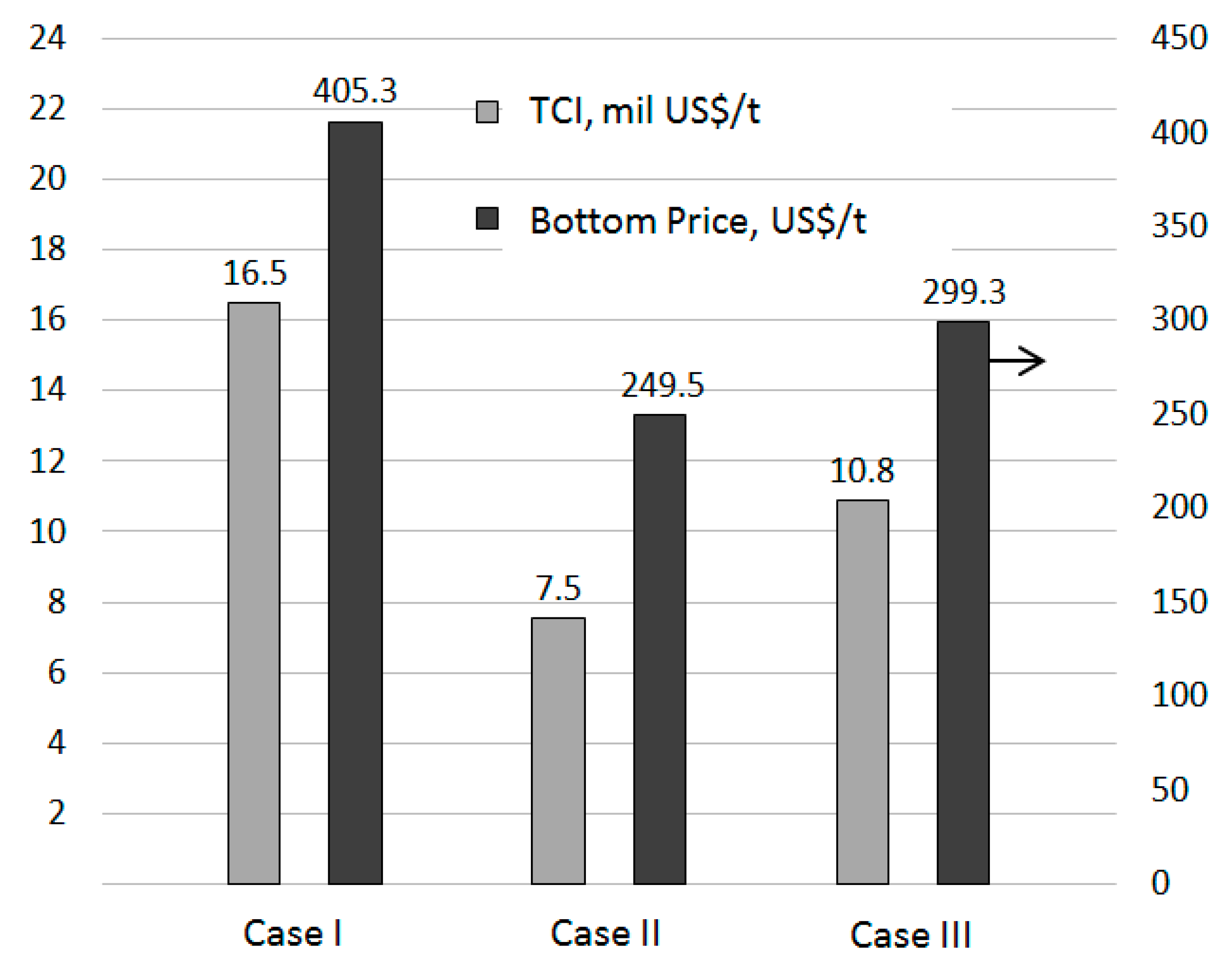
The total revenue requirement method is applied to evaluate the processes from an economic point of view. Figure 7 presents a comparison of the specific total capital investment and the cost per ton of produced methanol. The cost is calculated as the ratio of the TRR and the capacity of the plant.
The total capital investment for Case I amounts to 520 mil. US$, while it is 420 mil. US$ for Case II and 640 mil. US-$ for Case III. As shown in Figure 7, the total capital investment per ton of methanol is the highest for Case I. The plant design requires large air compression units and an SMR furnace, which are both capital intensive. Also in case III, the largest investment is assigned to the air- and syngas compressors (CM-03–CM-06) as well as the furnace R-06. The investment for the synthesis reactor R-07, the DMR R-04 and the GHR R-05 is of minor significance, because these components are designed as tubular shell and tube heat exchangers with high temperature materials. Despite of the higher production capacity of the plant in Case II, the investment is lower than for the design in Case I. This is due to the smaller sizes of the air compression unit, the furnace, and all other components in the flue gas line. The current price (May 2017) per ton of methanol of the main supplier Methanex on the largest sales market Asia is 350 US$. Taking this into account, the plant in Case I is economically not feasible. Due to the economies of scale effect, the plant designs with a combination of different reforming technologies at higher capacities can produce at a competitive cost.
5.3. Exergoeconomic Analysis
The exergoeconomic analysis represents a unique combination of an exergetic analysis and an economic analysis. For all design cases, a ranking of components according to their cost influence is given in Table 6. For a comparison of the cases with different capacity, the cost rate associated with the investment and the exergy destruction () is related to the exergy of product. In addition, an objective for improvement can be derived for each component by considering the exergoeconomic factor . High values of suggest a decrease of the investment cost, while low values recommend an increase in the exergetic efficiency in order to reduce the cost rate associated with the exergy destruction.
In particular, the combustion units, the air and syngas compressors, and the turbomachinery have a high cost impact. Single heat exchangers in the heat recovery unit (sub-system V) also have a significant influence on the expenses. Gas- and steam heated tubular reactors (R-05 in Case I, R-04 and R-08 in Case II, R-04, R05 and R07 in Case III) have comparatively small cost rates. In the following, the most important components of the cases are discussed.
The direct fired steam reformer in Case I has the largest effect on the overall cost, because of the cost of exergy destruction within it. Large irreversibilities are related to the mixing of natural gas, purge gas and air as well as to the combustion reaction and the heat transfer to the tubes. Furthermore, the syngas reacts with steam in a highly irreversible catalytic reaction taking place within the tubes. The low value of the exergoeconomic factor indicates the dominant cost influence of the irreversibilities within this component. Mainly due to the high investment cost, the air compressors CM-01 and CM-02 are rated to positions two and three. The f-value is close to one, suggesting a decrease in investment cost by accepting larger irreversibilities. This also applies to the components T-01, T-02, CM-04 and CM-06, whereby their influence on the overall cost is of lower significance.
In Case II the furnace R-07 is ranked to position number one, having the highest relative cost impact among all components. This is due to the destruction (to a large extent) of the costly exergy stream of the purge gas from the synthesis loop (stream 12) and the costly exergy stream from the air compression unit. Downstream of R-07, the high cost impacts of the medium pressure evaporator (MP-EVA) and the economizer (MP-ECO) are accordingly caused by the supply of costly exergy (flue gas) in conjunction with the high irreversibilities due to heat transfer. The high specific cost of the flue gas (stream 9 in Table 5) also results from the investment cost of the air compression unit (CM-02), which is rated to position number three. The component has an exergoeconomic factor of , which recommends a reduction of the investment cost by accepting higher exergy destruction. At position number five, the costs of the refining column C-02 are mainly assigned to the exergy destruction caused by heat transfer. The expander T-01 is rated to position number six, whereby the relative cost rate is mainly caused by the exergy destruction within it. The combustion chamber of the ATR R-05 is associated with a high cost because of the irreversibilities caused by the POX reaction. In addition, the syngas compressors are listed at position seven and nine. The f-value shows a balance of the cost impact through exergy destruction and investment, so that no decision for improvement can be derived here.
As in Case II, the furnace R-09 also has the highest relative cost impact among all components in Case III. The low-pressure and medium-pressure economizers are rated to position number two and three, whereby the cost related to exergy destruction have a dominant role. Here, the cost of the exergy of fuel has less influence than the large irreversibilities due to heat transfer at large temperature differences. The f-factor implies a reduction of the irreversibilities by increasing for example the area of the heat exchangers. The cost of the low-pressure turbine (T-01) is mainly caused by irreversibilities due to friction of droplets in the last stages of the expander. The turbine has a steam quality of x = 0.93 at the outlet. Having a smaller relative cost impact, a set of compressors follows on the positions 5–8. As with all other compressors, the investment costs mainly cause the relative cost rates associated with these components: the steam-turbine-driven air compression units (CM-03 and CM-04) and the compressors for pressure control in the reforming (CM-01 and CM-02) unit have an f-value between 0.8 and 0.9. An interesting observation can be made for the gas-heated reactors, the cost impact of which is relatively low. The design of such reactors is similar to a shell and tube heat exchanger and therefore not capital intensive. Moreover, convective heat transfer substitutes the highly irreversible radiant heat transfer from direct firing of fuel in a furnace. In addition, the temperature profiles are regulated for relatively small temperature differences and low exergy destruction.
6. Conclusions
In the present study, an exergy analysis, an economic analysis and an exergoeconomic analysis were conducted to evaluate different plant designs of methanol production from natural gas from a thermodynamic and an economic point of view. The exergy concept provided information concerning the real thermodynamic inefficiencies within each component and the overall systems. Subsequently, an economic analysis using the TRR method served for studying the economic feasibility of the designs. The exergoeconomic analysis identified the components with the highest cost impact and revealed the potential of a system improvement with respect to product cost minimization.
Regarding the three system designs, exergetic efficiencies of 28.2%, 55.6% and 41% were calculated for Cases I, II, and III, respectively. The main sources of inefficiencies are related to chemical reactions within furnaces and to heat transfer within several heat exchangers in the heat recovery steam generator. The findings of the economic analysis show that Case I is economically not feasible considering current market prices for methanol. Design Cases II and III at higher production capacities produce methanol below the current market price and have an amortization of three and six years, respectively. The exergoeconomic analysis revealed that the furnaces of the reforming unit have the highest cost impact of all components. Furthermore, the investment cost of the air and syngas compression units have a significant contribution to the overall cost. In particular, several heat exchangers in the heat recovery unit offer a high potential for further cost reductions.
Author Contributions
T.B. conducted the simulations and the analyses. All three authors contributed to the evaluation of the obtained results and to the text writing.
Conflicts of Interest
The authors declare no conflict of interest.
References
- Methanol Market Services Asia (MMSA). Methanol and Derivates Analysis (MDA); Methanol Market Services Asia (MMSA): Singapore, 2016; Volume 11. [Google Scholar]
- Alvarado, M. The changing face of the global methanol industry. IHS Chem. Bull. Insights 2016, 3, 10–11. Available online: https://cdn.ihs.com/www/pdf/IHS-Chemical-Bulletin-2016-Issue-3.pdf (accessed on 21 November 2017).
- Olah, G.; Goeppert, A.; Prakash, G.K.S. Beyond Oil and Gas: The Methanol Economy, 2nd ed.; Wiley VCH Verlag GmbH & Co. KGaA: Los Angeles, CA, USA, 2009. [Google Scholar]
- Cheng, W.H.; Kung, H. Methanol production and use. In Chemical Industries; CRC Press: Boca Raton, FL, USA, 1994. [Google Scholar]
- Jörg, O.; Gronemann, V.; Pontzen, F.; Fiedler, E.; Grossmann, G.; Kersebohm, D.B.; Weiss, G.; Witte, C. Methanol. In Ullmann’s Encyclopedia of Industrial Chemistry; Wiley-VCH Verlag GmbH & Co. KGaA: Weinheim, Germany, 2012. [Google Scholar]
- Aasberg-Petersen, K.; Stub Nielsen, K.; Dybkjær, I.; Perregaard, J. Large Scale Methanol Production from Natural Gas; Research Paper; Haldor Topsøe: Lyngby, Denmark, 2014. [Google Scholar]
- Aasberg-Petersen, K.; Bak Hansen, J.-H.; Christensen, T.S.; Dybkjaer, I.; Seier Christensen, P.; Stub Nielsen, C.; Winter Madsen, S.E.L.; Rostrup-Nielsen, J.R. Technologies for large-scale gas conversion. Appl. Catal. A Gen. 2001, 221, 379–387. [Google Scholar] [CrossRef]
- Dahl, P.J.; Christensen, T.S.; Winter-Madsen, S.; King, S.M. Proven autothermal reforming technology for modern large-scale methanol plants. In Proceedings of the International Conference on Nitrogen+ Syngas, Paris, France, 24–27 February 2014. [Google Scholar]
- Rostrup-Nielsen, J.R. Catalytic Steam Reforming; Springer Verlag: Berlin/Heidelberg, Germany; Tokyo, Japan; New York, NY, USA, 1984. [Google Scholar]
- Rostrup-Nielsen, J.R.; Sehested, J.; Nørskov, J.K. Hydrogen and Synthesis Gas by Steam and CO2 Reforming. Adv. Catal. 2002, 47, 65–139. [Google Scholar] [CrossRef]
- Holm-Larsen, H. CO2-reforming for large scale methanol plants—An actual case. In Natural Gas Conversion VI; Studies in Surface Science Catalysis Book Series; Elsevier: Amsterdam, The Netherlands, 2001; pp. 441–446. [Google Scholar]
- Pakhare, D.; Spivey, J. A review of dry (CO2) reforming of methane over noble metal catalysts. Chem. Soc. Rev. 2014, 43, 7813–7837. [Google Scholar] [CrossRef] [PubMed]
- Khoshtinat Nikoo, M.; Amin, N.A.S. Thermodynamic analysis of carbon dioxide reforming of methane in view of solid carbon formation. Fuel Process. Technol. 2011, 92, 678–691. [Google Scholar] [Green Version]
- Baltrusaitis, J.; Luyben, W.L. Methane Conversion to Syngas for Gas-to-Liquids (GTL): Is Sustainable CO2 Reuse via Dry Methane Reforming (DMR) Cost Competitive with SMR and ATR Processes. ACS Sustain. Chem. Eng. 2015, 3, 2100–2111. [Google Scholar] [CrossRef]
- Noureldin, M.M.B.; Elbashir, N.O.; Gabriel, K.J.; El-Halwagi, M.M. A Process Integration Approach to the Assessment of CO2 Fixation through Dry Reforming. ACS Sustain. Chem. Eng. 2015, 3, 625–636. [Google Scholar] [CrossRef]
- Luyben, W.L. Control of parallel dry methane and steam methane reforming processes for Fischer–Tropsch syngas. J. Process Control 2016, 39, 77–87. [Google Scholar] [CrossRef]
- Zhang, C.; Jun, K.; Gao, R.; Kwak, G.; Park, H. Carbon dioxide utilization in a gas-to-methanol process combined with CO2/Steam-mixed reforming: Techno-economic analysis. Fuel 2017, 190, 303–311. [Google Scholar] [CrossRef]
- Machado, C.F.R.; de Medeiros, J.L.; Araújo, O.F.Q. A comparative analysis of methanol production routes: Synthesis gas versus CO2 hydrogenation. In Proceedings of the 2014 International Conference on Industrial Engineering and Operations Management, Bali, Indonesia, 7–9 January 2014. [Google Scholar]
- Luu, M.; Milani, D.; Bahadori, A.; Abbas, A. A comparative study of CO2 utilization in methanol synthesis with various syngas production technologies. J. CO2 Util. 2015, 12, 62–76. [Google Scholar] [CrossRef]
- Rosen, A.; Scott, D. Energy and Exergy Analyses of a Production Process for Methanol from Natural Gas. Int. J. Hydrogen Energy 1988, 13, 617–623. [Google Scholar] [CrossRef]
- Wender, I. Reactions of Synthesis Gas. Fuel Process. Technol. 1996, 48, 189–297. [Google Scholar] [CrossRef]
- Dybkjaer, I.; Christensen, T.S. Syngas for large scale conversion of natural gas to liquid fuels. Stud. Surf. Sci. Catal. 2001, 136, 435–440. [Google Scholar]
- Spath, P.L.; Dayton, D.C. Preliminary Screening—Technical and Economic Assessment of Synthesis Gas to Fuels and Chemicals with Emphasis on the Potential for Biomass-Derived Syngas; Technical Report NREL/TP-510-34929; National Renewable Energy Laboratory: Golden, CO, USA, 2003.
- Dybkjær, I.; Aasberg-Petersen, K. Synthesis gas technology large-scale applications. Can. J. Chem. Eng. 2016, 94, 607–612. [Google Scholar] [CrossRef]
- Rostrup-Nielsen, J.R.; Rostrup-Nielsen, T. Large-scale Hydrogen Production. In Proceedings of the 6th World Congress of Chemical Engineering, Melbourne, Australia, 23–27 September 2001. [Google Scholar]
- Zahedi, N.M.; Rowshanzamir, S.; Eikani, M.H. Autothermal reforming of methane to synthesis gas: Modeling and simulation. Int. J. Hydrogen Energy 2009, 34, 1292–1300. [Google Scholar]
- Molburg, J.; Doctor, R. Hydrogen from Steam-Methane Reforming with CO2-capture. In Proceedings of the 20th Annual International Pittsburgh Coal Conference, Pittsburgh, PA, USA, 15–19 September 2003. [Google Scholar]
- Hansen, J.B. Methanol Production Technology: Todays and Future Renewable Solutions; Methanol Workshop, Lund University; Haldor Topsøe: Lyngby, Denmark, 2015. [Google Scholar]
- Wurzel, T. Lurgi MegaMethanol Technology. In Proceedings of the DGMK-Conference, Dresden, Germany, 4–6 October 2006. [Google Scholar]
- Wesenberg, M.H. Gas Heated Steam Reformer Modelling. Ph.D. Thesis, Norwegian University of Science and Technology, Trondheim, Norway, 2006. [Google Scholar]
- Chen, L.; Jiang, Q.; Zhaozheng, S.; Posarac, D. Optimization of Methanol Yield from a Lurgi Reactor. Chem. Eng. Technol. 2011, 34, 817–822. [Google Scholar] [CrossRef]
- Sinadinović-Frišer, S.V.; Janković, M.R.; Radicević, R.Ž. Simulation of the fixed bed Reactor for methanol synthesis. Pet. Coal 2001, 43, 31–34. [Google Scholar]
- Vanden Bussche, K.M.; Froment, G.F. A steady-state kinetic model for methanol synthesis and the water-gas shift reaction on a commercial Cu/ZnO/Al2O3 catalyst. J. Catal. 1996, 161, 1–10. [Google Scholar] [CrossRef]
- Luyben, W.L. Chemical Reactor Design and Control; John Wiley & Sons, Inc.: Hoboken, NJ, USA, 2006. [Google Scholar]
- Brasington, R.D.; Haslbeck, J.L.; Kuehn, N.J.; Lewis, E.G.; Pinkerton, L.L.; Turner, M.; Varghese, E.; Woods, M. Cost and Performance Baseline for Fossil Energy Plants—Volume 2: Coal to Synthetic Natural Gas and Ammonia; DOE/NETL-2010/1402; National Energy Laboratory: Lakewood, CO, USA, 2011. [Google Scholar]
- Bejan, A.; Tsatsaronis, G.; Moran, M. Thermal Design & Optimization; John Wiley & Sons, Inc.: Hoboken, NJ, USA, 1996; ISBN 978-0471584674. [Google Scholar]
- Szargut, J.; Morris, D.R.; Steward, F.R. Exergy Analysis of Thermal, Chemical, and Metallurgical Processes; Hemisphere: Bay Shore, NY, USA, 1988. [Google Scholar]
- Lazzaretto, A.; Tsatsaronis, G. SPECO: A systematic and general methodology for calculating efficiencies and costs in thermal systems. Energy 2006, 31, 1257–1289. [Google Scholar] [CrossRef]
- Ulrich, G.D.; Vasudevan, P.T. Chemical Engineering Process Design and Economics: A Practical Guide; Process Publishing: Durham, UK, 2002; ISBN 978-0849320330. [Google Scholar]
- Loh, H.P. Process Equipment Cost Estimation Final Report; DOE/NETL-2002/1169; National Energy Laboratory: Lakewood, CO, USA, 2002. [Google Scholar]
- Towler, G.; Sinnott, R.K. Chemical Engineering Design: Principles, Practice and Economics of Plant and Process Design, 2nd ed.; Elsevier Ltd.: Oxford, UK, 2007; ISBN 978-0080966595. [Google Scholar]
- De María, R.; Díaz, I.; Rodríguez, M.; Sáiz, A. Kinetic study and process simulation. Int. J. Chem. React. Eng. 2013, 11, 469–477. [Google Scholar]
- Luyben, W.L. Design and Control of a methanol reactor/column process. Ind. Eng. Chem. Res. 2010, 49, 6150–6163. [Google Scholar] [CrossRef]
- Hawkins, G. Methanol Plant, Theory of Distillation. Available online: https://de.slideshare.net/GerardBHawkins/methanol-plant-theory-of-distillation (accessed on 10 November 2017).
- Amirkhas, E.; Bedi, R.; Harley, S.; Lango, T. Methanol Production in Trinidad & Tobago; Final Report; University of California: Oakland, CA, USA, 2006. [Google Scholar]
- Tesch, S.; Morosuk, T.; Tsatsaronis, G. Exergoeconomic analysis applied to the process of regasification of LNG integrated into an air separation process. In Proceedings of the ECOS 2015—The 29th Conference on Efficiency, Cost, Optimization, Simulation and Environmental Impact of Energy Systems, Pau, France, 29 June–3 July 2015. [Google Scholar]
Figure 1.
Range of the syngas composition for the commercially applied methane reforming technologies. The composition is expressed by the three main stoichiometric modules.
Figure 1.
Range of the syngas composition for the commercially applied methane reforming technologies. The composition is expressed by the three main stoichiometric modules.

Figure 2.
Ternary diagram for the methanol yield at an equilibrium pressure of 50 bar and an equilibrium temperature of 250 °C for a given inlet composition. The syngas composition for the basic reforming technologies SMR, ATR and DMR and the investigated cases are shown.
Figure 2.
Ternary diagram for the methanol yield at an equilibrium pressure of 50 bar and an equilibrium temperature of 250 °C for a given inlet composition. The syngas composition for the basic reforming technologies SMR, ATR and DMR and the investigated cases are shown.

Figure 3.
Process flow sheet of the methanol plant with steam–methane reforming (Case I).

Figure 4.
Process flow sheet of the methanol plant with steam-methane and autothermal reforming in serial configuration (Case II).
Figure 4.
Process flow sheet of the methanol plant with steam-methane and autothermal reforming in serial configuration (Case II).

Figure 5.
Process flow sheet of the methanol plant with parallel steam-methane and dry reforming (Case III).
Figure 5.
Process flow sheet of the methanol plant with parallel steam-methane and dry reforming (Case III).
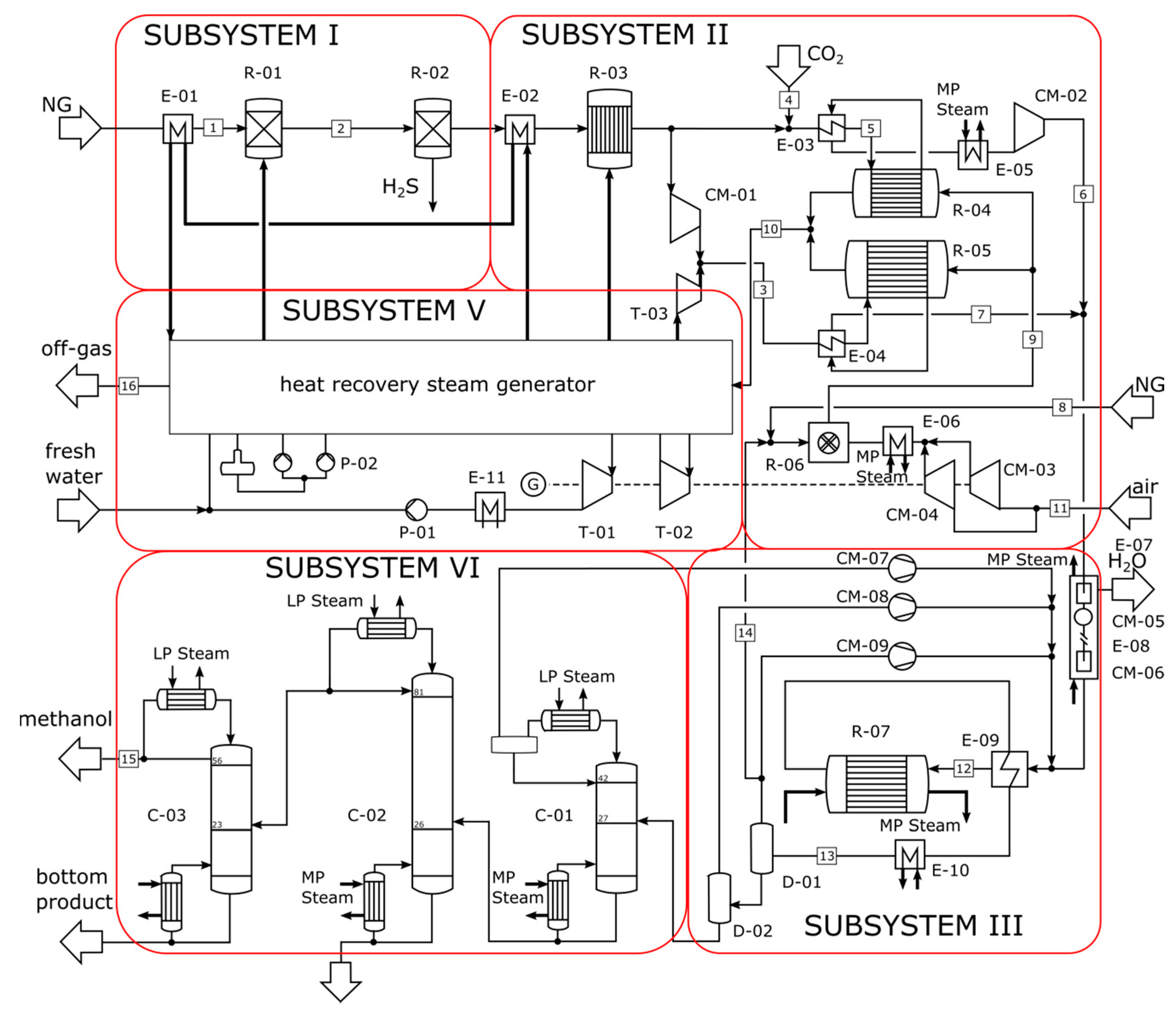
Figure 6.
Comparison of the cases using results from the exergy analyses.

Figure 7.
Comparison of the design cases using some results from the economic analyses.


Table 1.
Overview of the main reforming reactions.
| Reforming Type | Main Reactions | Δh0 |
|---|---|---|
| SMR [25] | CH4 + H2O → CO + 3H2 | 206 kJ/mol |
| CO + H2O → CO2 + H2 | −41 kJ/mol | |
| ATR [10] | CH4 + 1.5 O2 → CO + 2H2O | −520 kJ/mol |
| CO + H2O → CO2 + H2 | −41 kJ/mol | |
| CH4 + H2O → CO + 3H2 | 206 kJ/mol | |
| DMR [10,26] | CH4 + CO2 → 2CO + 2H2 | 247 kJ/mol |
Table 2.
Overview of major assumptions made for modeling the plant designs in Aspen Plus.
| Component/System | Unit | Case I | Case II | Case III |
|---|---|---|---|---|
| General | ||||
| Property Model | Redlich–Kwong–Soave | |||
| Ambient Temperature | °C | 15 | 15 | 15 |
| Ambient Pressure | bar | 1.013 | 1.013 | 1.013 |
| Mechanical Efficiency | % | 99 | 99 | 99 |
| Compressor isentropic efficiency | % | 85 | 85 | 85 |
| Pretreatment (sub-system I) | ||||
| Hydrogenolysis | ||||
| Conversion rate of COS [35] | % | 99.5 | 99.5 | 99.5 |
| Zinc Oxide Guard Bed | ||||
| H2S absorption coefficient [35] | % | 99.9 | 99.9 | 99.9 |
| Reforming Unit (sub-system II) | ||||
| Steam reformer (SMR and GHR design) | ||||
| Catalyst Density | kg/m3 | 2000 | 2000 | 2000 |
| Void Fraction | - | 0.5 | 0.5 | 0.5 |
| Number of Tubes | - | 3500 | 6000 | 1600 |
| Length | m | 12 | 10 | 15 |
| Diameter | m | 0.1 | 0.01 | 0.1 |
| Heat Transfer Coefficient | kW/m2K | 0.5 | 0.5 | 0.5 |
| S/C-ratio | - | 3.5 | 0.5 | 1.0 |
| Autothermal Reformer (The information refers to the catalytic bed of the ATR) and Dry Methane Reformer | ||||
| Catalyst Density | kg/m3 | - | 2500 | 2000 |
| Void Fraction | - | - | 0.5 | 0.5 |
| Number of Tubes | - | - | - | 550 |
| Length | m | - | 7 | 13.5 |
| Diameter | m | - | 3 | 0.1 |
| Heat Transfer Coefficient | kW/m2K | - | - | 0.5 |
| O2/C-ratio, CO2/C-ratio | - | 0.55 | 0.5 | |
| Methanol Synthesis Unit (sub-system III) | ||||
| Catalyst Density | kg/m3 | 1775 | 1775 | 1775 |
| Void Fraction | - | 0.5 | 0.5 | 0.5 |
| Number of Tubes | - | 10,000 | 10,000 | 10,000 |
| Length | m | 18 | 18 | 18 |
| Diameter | m | 0.037 | 0.037 | 0.037 |
| Heat Transfer Coefficient | kW/m2K | 0.28 | 0.28 | 0.28 |
| Purge Ratio | % | 5 | 10 | 20 |
| Purification (sub-system IV) | ||||
| Topping Column | ||||
| Reflux Ratio | - | 0.6 | 0.6 | 0.6 |
| Distillate to Feed Mole Ratio | - | 0.3 | 0.1 | 0.1 |
| Pressure Column | ||||
| Reflux Ratio | - | 0.75 | 0.6 | 0.75 |
| Distillate to Feed Mole Ratio | - | 0.9 | 0.95 | 0.95 |
| Atmospheric Column | ||||
| Reflux Ratio | - | 0.9 | 0.8 | 0.8 |
| Distillate to Feed Mole Ratio | - | 0.77 | 0.95 | 0.95 |
| Steam Cycle (sub-system V) | ||||
| steam turbine (driver) isentropic efficiency | - | 0.92 | 0.92 | 0.92 |
| condenser pressure | bar | 0.05 | 0.05 | 0.05 |
Table 3.
Stream data of the methanol plant with steam–methane reforming (Case I).
| Stream | Units | 1 | 2 | 3 | 4 | 5 | 6 | 7 | 8 |
| kg/s | 16.88 | 16.90 | 1.31 | 18.20 | 1634.26 | 40.22 | 26.19 | 1586.00 | |
| t | °C | 15.00 | 124.57 | 550.00 | 509.55 | 884.75 | 117.10 | 15.00 | 15.00 |
| p | bar | 10.00 | 29.00 | 29.50 | 26.70 | 6.50 | 50.00 | 10.00 | 1.01 |
| % (mole) | 0.00 | 0.00 | 0.00 | 0.00 | 0.00 | 75.74 | 0.00 | 0.00 | |
| % (mole) | 0.00 | 0.00 | 0.00 | 0.96 | 0.00 | 15.59 | 0.00 | 0.00 | |
| % (mole) | 0.70 | 0.72 | 0.00 | 0.68 | 3.68 | 7.60 | 0.70 | 0.00 | |
| % (mole) | 94.90 | 94.81 | 0.00 | 91.17 | 0.00 | 0.69 | 94.90 | 0.00 | |
| % (mole) | 0.00 | 0.08 | 100.00 | 5.74 | 7.62 | 0.00 | 0.00 | 0.00 | |
| % (mole) | 0.00 | 0.00 | 0.00 | 0.00 | 0.00 | 0.00 | 0.00 | 0.00 | |
| e | MJ/kg | 49.66 | 49.79 | 1.49 | 46.85 | 0.73 | 25.07 | 49.66 | 0.00 |
| Stream | Units | 9 | 10 | 11 | 12 | 13 | 14 | 15 | 16 |
| kg/s | 13.50 | 351.62 | 351.62 | 276.06 | 2.40 | 58.62 | 31.32 | 1630.63 | |
| t | °C | 45.00 | 250.00 | 38.00 | 38.52 | 38.00 | 38.00 | 70.97 | 100.00 |
| p | bar | 50.00 | 50.00 | 49.30 | 48.50 | 2.00 | 2.00 | 1.30 | 4.80 |
| % (mole) | 0.00 | 67.99 | 63.84 | 69.46 | 3.03 | 0.00 | 0.00 | 0.00 | |
| % (mole) | 0.00 | 10.18 | 8.81 | 9.58 | 0.99 | 0.00 | 0.00 | 0.00 | |
| % (mole) | 100.00 | 15.88 | 15.40 | 16.50 | 81.24 | 0.65 | 0.00 | 3.67 | |
| % (mole) | 0.00 | 2.09 | 2.25 | 2.45 | 1.33 | 0.00 | 0.00 | 0.00 | |
| % (mole) | 0.00 | 0.05 | 1.75 | 0.05 | 0.95 | 21.65 | 0.08 | 7.55 | |
| % (mole) | 0.00 | 2.65 | 6.70 | 0.62 | 12.08 | 77.69 | 99.92 | 0.00 | |
| e | MJ/kg | 0.65 | 18.64 | 18.34 | 18.30 | 3.10 | 19.20 | 22.42 | 0.17 |
Table 4.
Stream data of the methanol plant with steam–methane and autothermal reforming in serial configuration (Case II).
Table 4.
Stream data of the methanol plant with steam–methane and autothermal reforming in serial configuration (Case II).
| Stream | Units | 1 | 2 | 3 | 4 | 5 | 6 | 7 | 8 |
| kg/s | 43.89 | 43.91 | 71.35 | 56.75 | 45.39 | 116.75 | 92.59 | 403.90 | |
| t | °C | 15.00 | 132.92 | 551.78 | 1157.35 | 550.00 | 1210.13 | 1168.38 | 231.80 |
| p | bar | 10.00 | 38.35 | 37.80 | 39.30 | 30.00 | 31.00 | 30.00 | 3.00 |
| % (mole) | 0.00 | 0.00 | 0.00 | 0.00 | 0.00 | 55.26 | 62.10 | 0.00 | |
| % (mole) | 0.00 | 0.00 | 0.66 | 0.00 | 0.00 | 25.49 | 32.16 | 0.00 | |
| % (mole) | 0.70 | 0.72 | 0.45 | 0.00 | 0.00 | 2.69 | 0.73 | 0.00 | |
| % (mole) | 94.90 | 94.86 | 62.08 | 0.00 | 0.00 | 0.00 | 0.01 | 0.00 | |
| % (mole) | 0.00 | 0.02 | 35.83 | 1.00 | 0.00 | 16.10 | 4.49 | 0.00 | |
| % (mole) | 0.00 | 0.00 | 0.00 | 0.00 | 0.00 | 0.00 | 0.00 | 0.00 | |
| e | MJ/kg | 49.66 | 49.87 | 31.62 | 2.60 | 0.61 | 18.68 | 22.87 | 0.16 |
| Stream | Units | 9 | 10 | 11 | 12 | 13 | 14 | 15 | 16 |
| kg/s | 429.16 | 320.66 | 320.66 | 25.26 | 71.35 | 2.86 | 55.08 | 429.16 | |
| t | °C | 1155.90 | 241.75 | 38.00 | 38.00 | 551.78 | 96.74 | 70.96 | 276.81 |
| p | bar | 2.50 | 49.00 | 45.00 | 45.00 | 37.80 | 3.00 | 1.30 | 1.20 |
| % (mole) | 0.00 | 60.54 | 53.50 | 59.35 | 0.00 | 0.00 | 0.00 | 0.00 | |
| % (mole) | 0.00 | 34.55 | 31.88 | 35.35 | 0.66 | 0.00 | 0.00 | 0.00 | |
| % (mole) | 4.99 | 1.87 | 2.14 | 2.30 | 0.45 | 0.00 | 0.00 | 4.99 | |
| % (mole) | 0.00 | 0.03 | 0.04 | 0.04 | 62.08 | 0.00 | 0.00 | 0.00 | |
| % (mole) | 7.90 | 0.00 | 0.07 | 0.00 | 35.83 | 14.11 | 0.00 | 7.90 | |
| % (mole) | 0.00 | 1.37 | 10.44 | 0.81 | 0.00 | 85.89 | 99.99 | 0.00 | |
| e | MJ/kg | 0.92 | 20.40 | 19.93 | 19.35 | 0.03 | 20.56 | 22.43 | 0.13 |
Table 5.
Stream data of the methanol plant with parallel steam-methane and dry reforming (Case III).
Table 5.
Stream data of the methanol plant with parallel steam-methane and dry reforming (Case III).
| Stream | Units | 1 | 2 | 3 | 4 | 5 | 6 | 7 | 8 |
| kg/s | 45.58 | 45.60 | 73.77 | 59.29 | 71.74 | 71.74 | 73.77 | 22.79 | |
| t | °C | 155 | 155.13 | 634.11 | 550.00 | 700.00 | 360.87 | 798.65 | 15.00 |
| p | bar | 9.90 | 9.19 | 30.00 | 9.00 | 8.64 | 29.50 | 29.70 | 5.00 |
| % (mole) | 0.00 | 0.00 | 0.00 | 0.00 | 0.00 | 25.60 | 68.82 | 0.00 | |
| % (mole) | 0.00 | 0.00 | 50.01 | 0.00 | 0.34 | 52.11 | 22.42 | 0.00 | |
| % (mole) | 0.70 | 0.72 | 0.34 | 1.00 | 64.52 | 6.99 | 0.78 | 0.70 | |
| % (mole) | 94.90 | 94.87 | 47.37 | 0.00 | 32.15 | 0.31 | 3.08 | 94.90 | |
| % (mole) | 0.00 | 0.02 | 51.03 | 0.00 | 2.48 | 14.67 | 4.48 | 0.00 | |
| % (mole) | 0.20 | 0.20 | 0.00 | 0.00 | 0.00 | 0.00 | 0.00 | 0.20 | |
| e | MJ/kg | 49.73 | 49.70 | 24.33 | 0.82 | 8.81 | 10.42 | 28.56 | 49.57 |
| Stream | Units | 9 | 10 | 11 | 12 | 13 | 14 | 15 | 16 |
| kg/s | 1996.38 | 1996.38 | 1904.12 | 420.90 | 420.90 | 69.46 | 58.41 | 1996.38 | |
| t | °C | 1151.02 | 893.41 | 15.00 | 250.00 | 38.00 | 38.01 | 70.96 | 320.08 |
| p | bar | 4.50 | 4.00 | 1.01 | 50.00 | 47.00 | 48.50 | 1.30 | 2.25 |
| % (mole) | 0.00 | 0.00 | 0.00 | 54.35 | 47.55 | 52.35 | 0.00 | 0.00 | |
| % (mole) | 0.00 | 0.00 | 0.00 | 31.71 | 28.33 | 31.17 | 0.00 | 0.00 | |
| % (mole) | 4.99 | 4.99 | 0.00 | 7.01 | 8.61 | 9.21 | 0.00 | 4.99 | |
| % (mole) | 0.00 | 0.00 | 0.00 | 4.34 | 5.03 | 5.52 | 0.00 | 0.00 | |
| % (mole) | 8.05 | 8.05 | 0.00 | 0.62 | 0.24 | 0.00 | 0.00 | 8.05 | |
| % (mole) | 0.61 | 0.00 | 0.00 | 1.23 | 9.39 | 0.79 | 1.00 | 0.00 | |
| e | MJ/kg | 25.22 | 0.71 | 0.01 | 18.70 | 18.29 | 17.67 | 22.43 | 0.22 |
Table 6.
Comparison of the cases using results from the exergoeconomic analyses.
| Nr. | Case I | Case II | Case III | ||||||
|---|---|---|---|---|---|---|---|---|---|
| Comp. | [-] | ()/ [$/MWh] | Comp. | [-] | ()/ [$/MWh] | Comp. | [-] | ()/ [$/MWh] | |
| 1 | R-04 | 0.09 | 16.42 | R-09 | 0.01 | 13.46 | R-06 | 0.10 | 8.62 |
| 2 | CM-01 | 0.92 | 5.95 | MP-EVA | 0.00 | 9.95 | LP-ECO | 0.00 | 3.58 |
| 3 | CM-02 | 0.92 | 5.95 | CM-02 | 0.83 | 4.63 | MP-ECO | 0.00 | 3.20 |
| 4 | T-01 | 0.83 | 1.30 | MP-ECO | 0.00 | 3.49 | T-01 | 0.37 | 2.73 |
| 5 | T-02 | 0.83 | 1.30 | C-02 | 0.13 | 1.62 | CM-03 | 0.82 | 2.49 |
| 6 | CM-06 | 0.95 | 1.11 | T-01 | 0.14 | 1.49 | CM-04 | 0.82 | 2.49 |
| 7 | CM-04 | 0.95 | 0.94 | CM-05 | 0.54 | 1.43 | CM-01 | 0.89 | 1.28 |
| 8 | C-02 | 0.38 | 0.92 | R-05 | 0.24 | 1.22 | CM-02 | 0.87 | 1.15 |
| 9 | C-01 | 0.22 | 0.70 | CM-06 | 0.48 | 0.97 | T-02 | 0.70 | 0.99 |
| 10 | R-05 | 0.50 | 0.52 | CM-01 | 0.80 | 0.89 | R-05 | 0.06 | 0.86 |
© 2017 by the authors. Licensee MDPI, Basel, Switzerland. This article is an open access article distributed under the terms and conditions of the Creative Commons Attribution (CC BY) license (http://creativecommons.org/licenses/by/4.0/).
Share and Cite
MDPI and ACS Style
Blumberg, T.; Morosuk, T.; Tsatsaronis, G. A Comparative Exergoeconomic Evaluation of the Synthesis Routes for Methanol Production from Natural Gas. Appl. Sci. 2017, 7, 1213. https://doi.org/10.3390/app7121213
AMA Style
Blumberg T, Morosuk T, Tsatsaronis G. A Comparative Exergoeconomic Evaluation of the Synthesis Routes for Methanol Production from Natural Gas. Applied Sciences. 2017; 7(12):1213. https://doi.org/10.3390/app7121213
Chicago/Turabian StyleBlumberg, Timo, Tatiana Morosuk, and George Tsatsaronis. 2017. "A Comparative Exergoeconomic Evaluation of the Synthesis Routes for Methanol Production from Natural Gas" Applied Sciences 7, no. 12: 1213. https://doi.org/10.3390/app7121213
Note that from the first issue of 2016, this journal uses article numbers instead of page numbers. See further details here.