A Transplantable Frequency Selective Metasurface for High-Order Harmonic Suppression


Key Laboratory of High Speed Circuit Design and EMC of Ministry of Education, School of Electronic Engineering, Collaborative Innovation Center of Information Sensing and Understanding, Xidian University, Xi’an 710071, China
*
Authors to whom correspondence should be addressed.
Appl. Sci. 2017, 7(12), 1240; https://doi.org/10.3390/app7121240
Submission received: 5 November 2017
/
Revised: 17 November 2017
/
Accepted: 23 November 2017
/
Published: 1 December 2017
(This article belongs to the Special Issue Metasurfaces: Physics and Applications)
Abstract
:A transplantable frequency selective metasurface element (FSMSE) for high-order harmonic suppression (HS) is presented in this paper. The proposed harmonic free FSMSE can be integrated with arbitrary frequency selective surfaces (FSSs) operating at the same frequency band. The designed HS-FSMSE is applied to two different types of FSSs for verification of harmonic suppression, respectively. One is a multilayer sub-wavelength patch-grid FSS that has weak resonant behavior, and the other is a complementary resonant loop FSS which has strong resonant behavior, especially for high-order harmonic waves. By integrating with HS-FSMSE, the two kinds of FSSs operating at 10 GHz are free of harmonic transmission bands up to 30 GHz. The simulation and measurement results show feasibility of the harmonic suppression FSMSW and good polarization and angle stabilities.
1. Introduction
Metasurfaces have been widely applied in manipulation of electromagnetic wave, such as radar radomes [1], spatial filters [2], reflect arrays [3], artificial impedance surfaces [4], polarization converters [5], and absorbing materials [6], etc., because of their properties of allowing uninhibited transmission of electromagnetic waves in specific frequency bands while suppressing transmission in other undesired bands. In general, a band-pass spatial filter based on metasurface is also called frequency selective surface (FSS) which is transparent within the operation frequency band of the antenna and opaque at other frequencies. However, most FSSs have multiple spurious transmission windows in higher operating frequency bands. And the high frequency harmonic phenomenon will severely interfere with other antennas and radars which operate at the h-armonic frequency bands especially on the low-observable or stealth platforms. As a result, the FSSs with harmonic suppression feature are important for practical applications.
In [7,8,9], band-pass frequency selective surfaces with stop-band characteristics are reported. They use artificial absorbing coating, resistive high-impedance surface, and other techniques to achieve the harmonic absorbing properties. However, the FSSs in these designs are specific which means the technique of these harmonic suppression FSSs cannot be independent and transplanted. In this paper, a transplantable frequency selective metasurface element for harmonic suppression is designed. The frequency selective metasurface element (FSMSE) are integrated with two different types of band-pass FSSs to remove the spurious transmission windows outside of the desired operational pass-band, respectively. Full-wave simulations and experiments show feasibility of the harmonic suppression FSMSE, and measured results agree well with simulated ones.
2. Design of the Harmonic-Suppression Frequency Selective Metasurface Element (FSMSE)
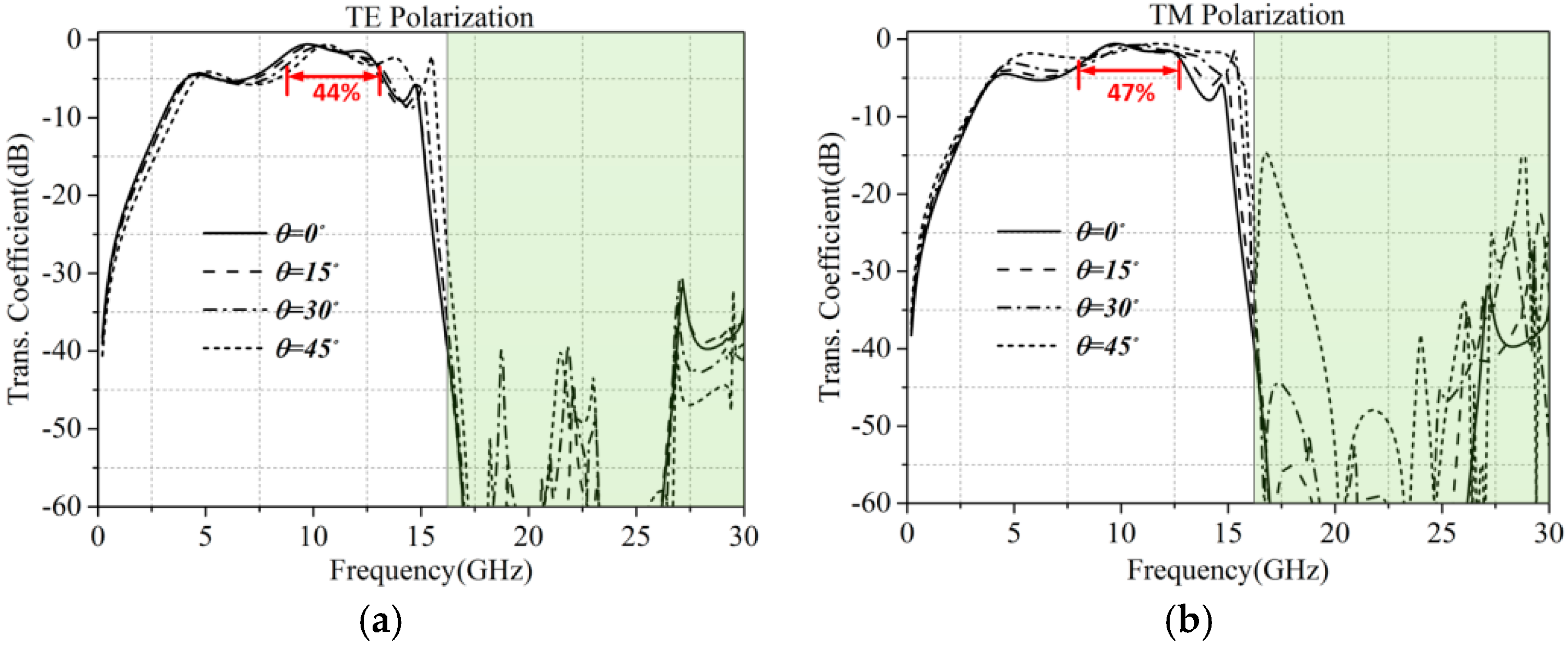
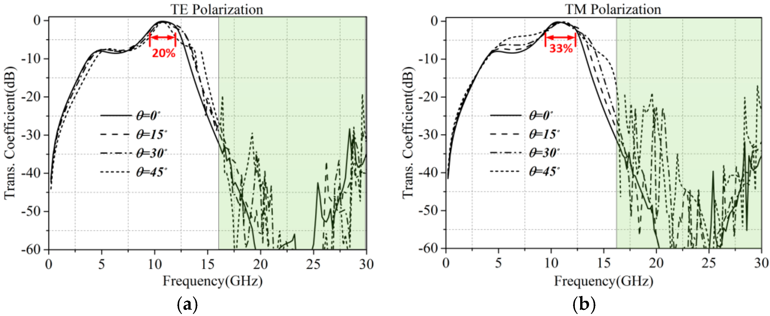
In general, a FSS with band-pass feature intrinsically has spurious transmission windows outside of the desired operational pass-band. For an example, a classic non-resonant FSS [7] which consists of square metallic patch with fishnet grids in multilayer structure is shown in Figure 1a. Full-wave analyses show that the pass-band characteristic of the FSS is operating at about 10 GHz, but with harmonic transmission bands around 25 GHz, as shown in Figure 2. When the plane wave is oblique incidence with Transverse Electric (TE) and Transverse Magnetic (TM) polarizations, the spurious transmission windows become much more. Similarly, a typical resonant type FSS which is composed of complementary loop structure [10] is shown in Figure 1b, which also operates at 10 GHz. Because the FSS is resonant structure, it has several harmonic pass bands at the higher frequency bands outside of the main pass-band, as shown in Figure 3. The geometry parameters of the two FSSs are shown in Table 1. Thus it can be seen that the harmonic suppression technique should be adopted. In this paper, a transplantable FSMSE is proposed that can be integrated with different types of band-pass FSS structures without deteriorating the operating frequency of the pass band.
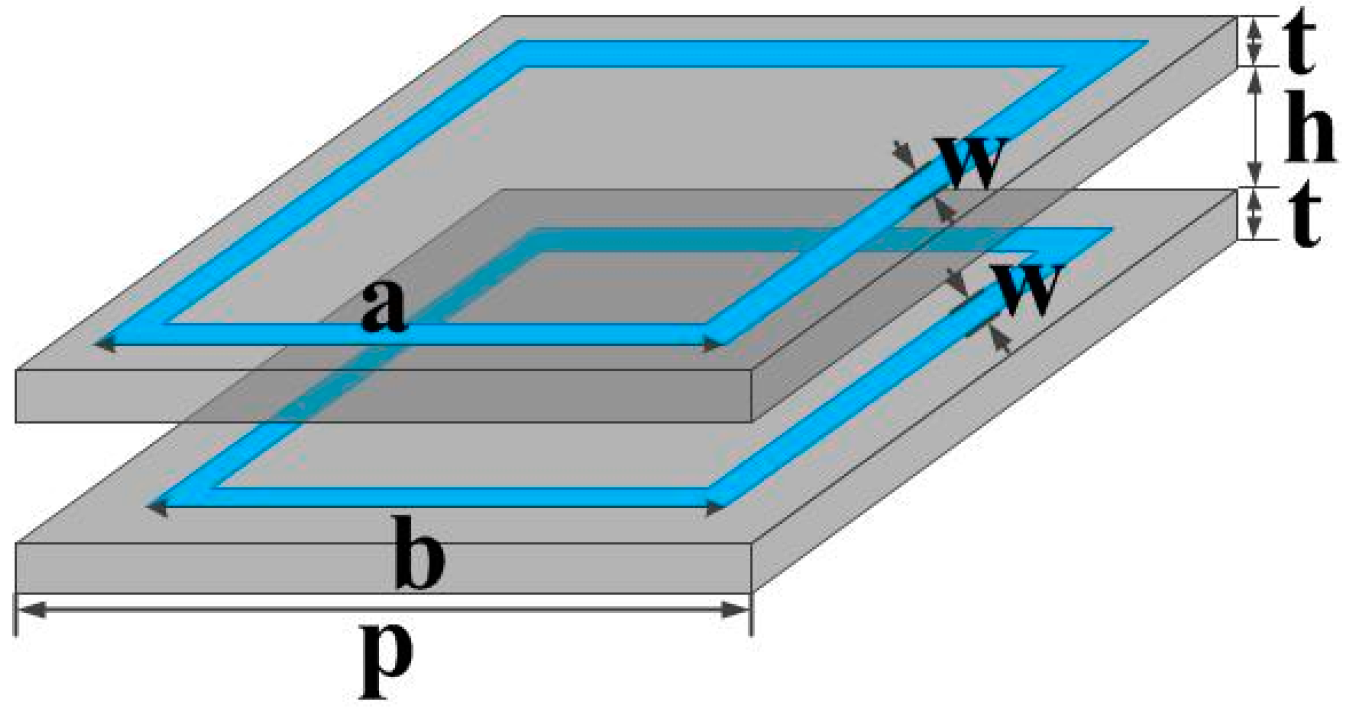
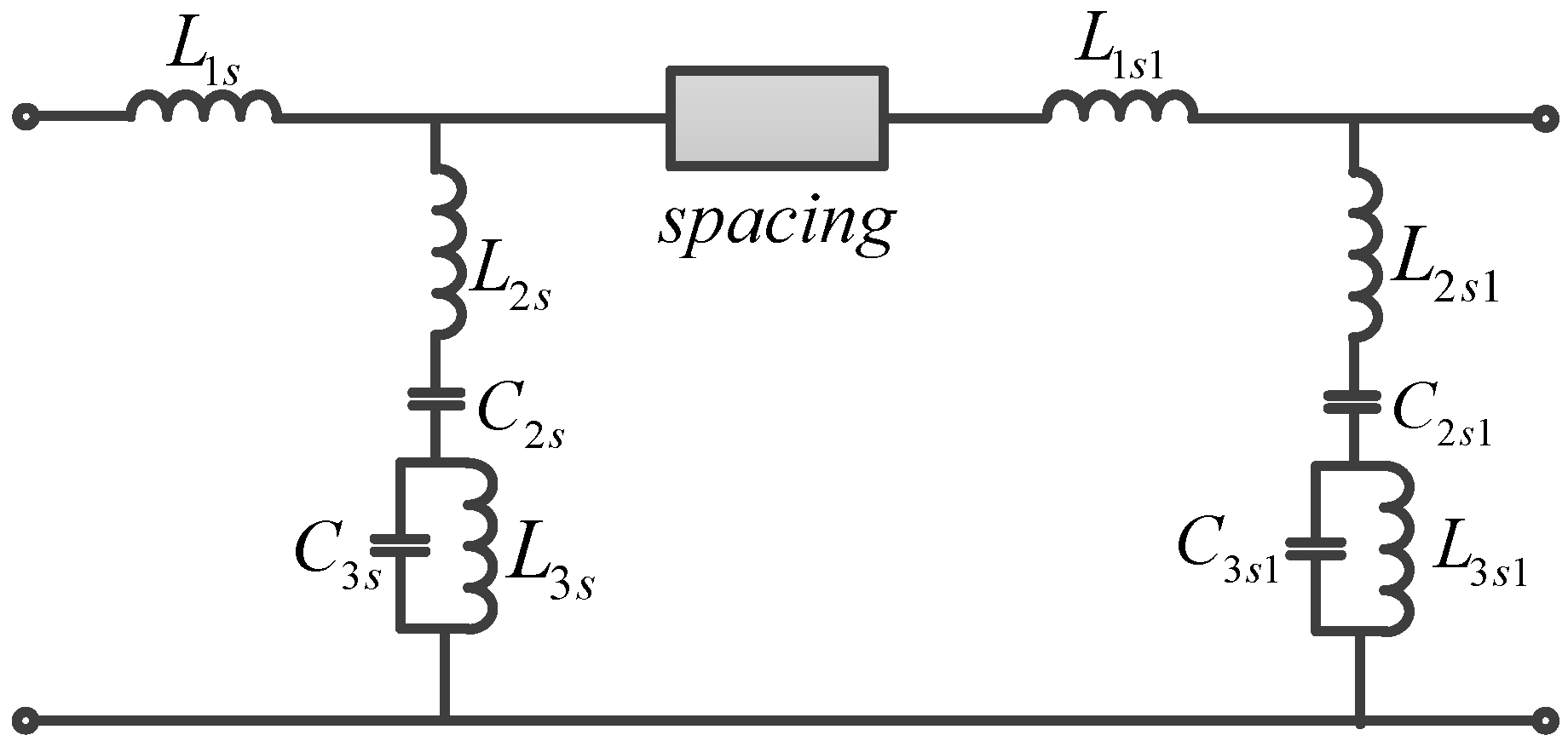
The topology of the FSMSE for harmonic suppression is shown in Figure 4, which is composed of two-layer square loop elements that intrinsically own band-stop feature. It is known that the single-layer square loop FSMSE has a narrow stop band whose operating frequency could be adjusted by changing the length of square loop. As a result, when we want to obtain a relatively wide stop band, the multilayer square loop FSMSE with air spacing can be designed. At the same time, the pass band of 10 GHz has to be guaranteed. The equivalent circuit model is used to analyze the feature of the FSMSE for harmonic suppression, as shown in Figure 5.
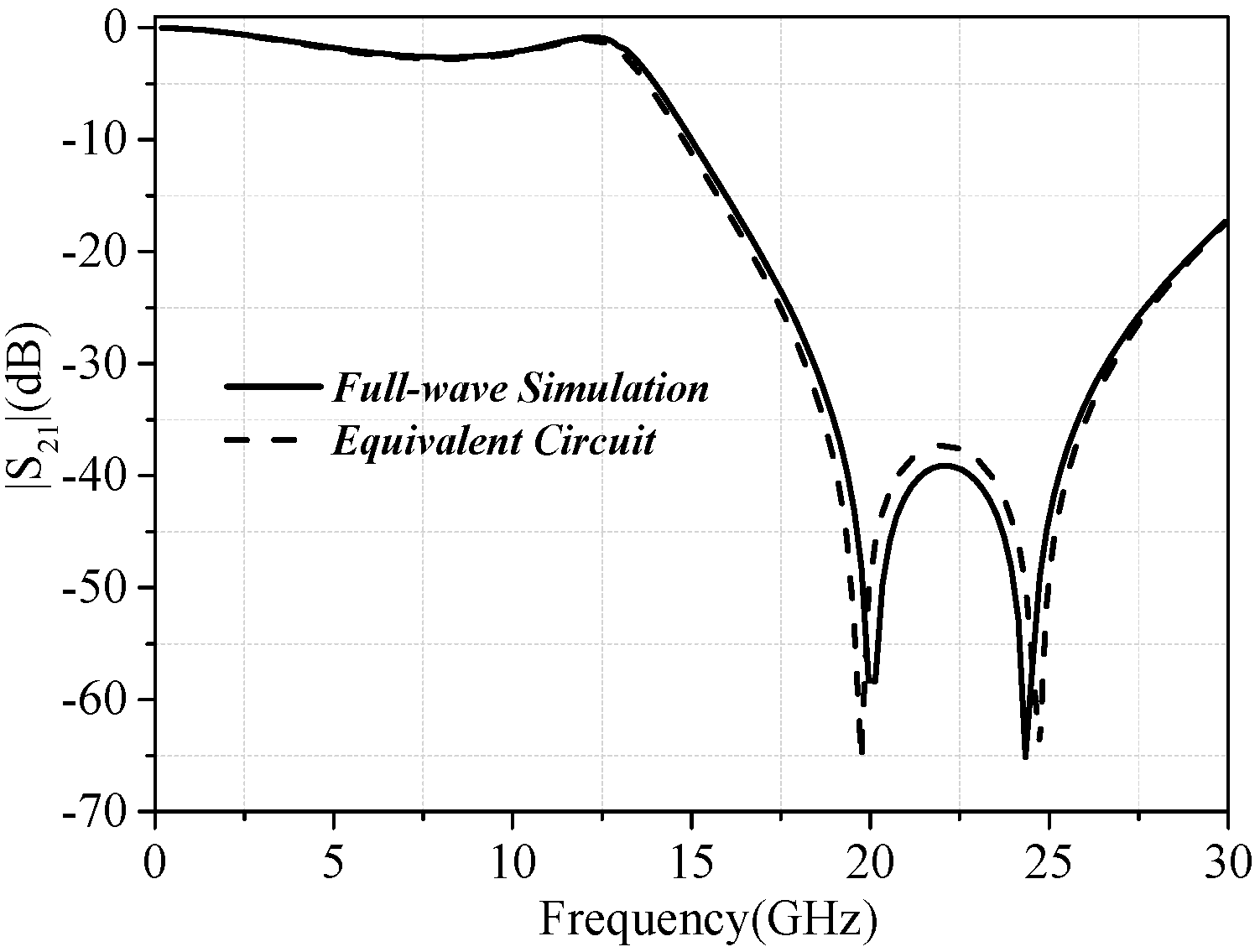
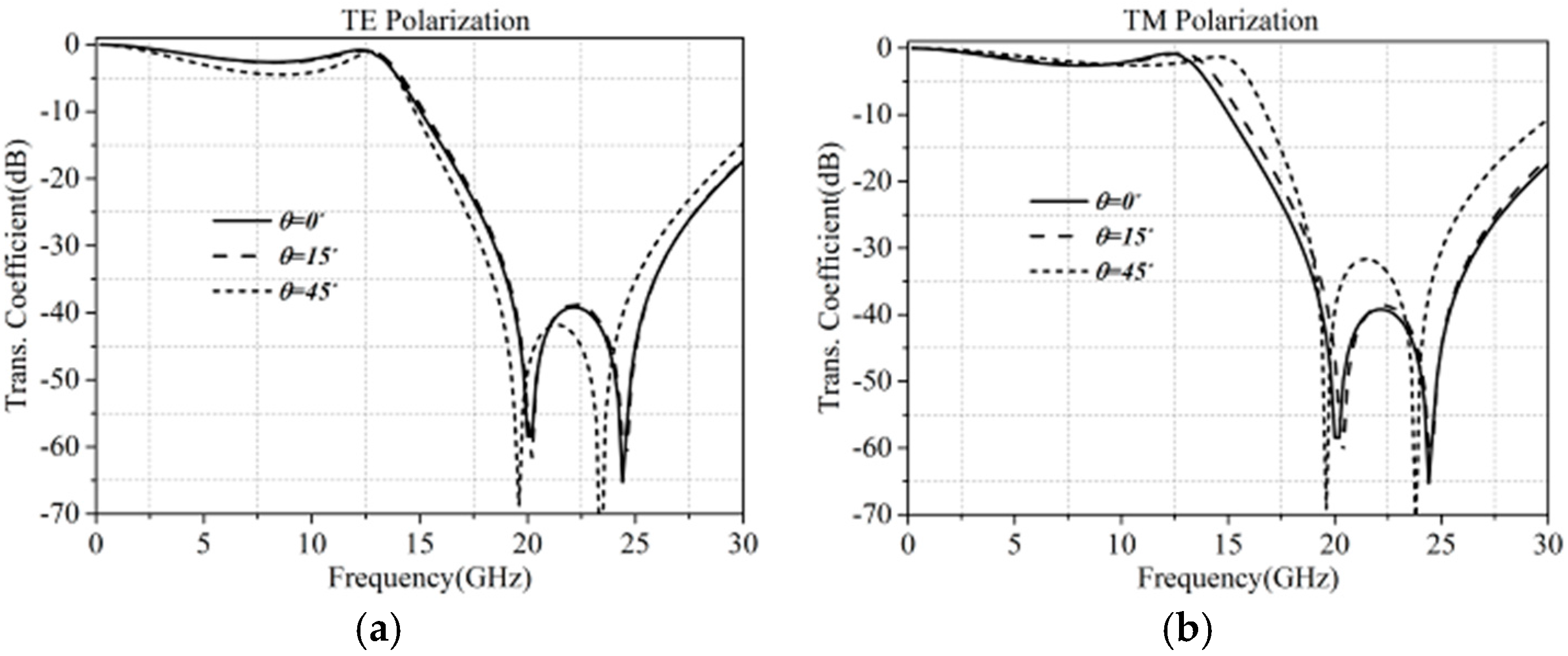
Here the square loop element can be equivalent to a band stop circuit. As a result, the equivalent circuit of the two-layer square loop FSMSE is a two-stage cascaded circuit which is connected by a uniform transmission line whose length depends on the electric size of the air spacing, as shown in Figure 5. The geometry parameters are shown in Table 2. The lumped elements in the equivalent circuit can be obtained using bisquare fitting algorithm [11]. According to the equivalent circuits of each layer of the square loop FSMSE, the lumped parameters are extracted as follows: L1s = L1s1 = 0.0834 nH, L2s = L2s1 = 0.001 nH, C2s = 0.6677 pF, C2s1 = 0.4462 pF, L3s = 0.0762 nH, L3s1 = 0.0624 nH, C3s = 0.1834 pF and C3s1 = 0.2167 pF. With these lumped elements and the circuit prototype, the optimal air spacing h could be obtained using circuit optimization. It can be seen that when h equals to 2 mm, the maximum stop-band range can be obtained. Figure 6 depicts the comparison of transmission coefficient of the harmonic suppression FSMSE between the full-wave simulation and the equivalent circuit, which shows good agreement with each other. Furthermore, the oblique incidences of TE and TM polarizations with different incident angles on the harmonic suppression FSMSE are analyzed, respectively, as shown in Figure 7. It can be seen that the proposed FSMSE has good polarization and angle stability. And the −20 dB suppression bandwidth is from 16.8 to 26.8 GHz.
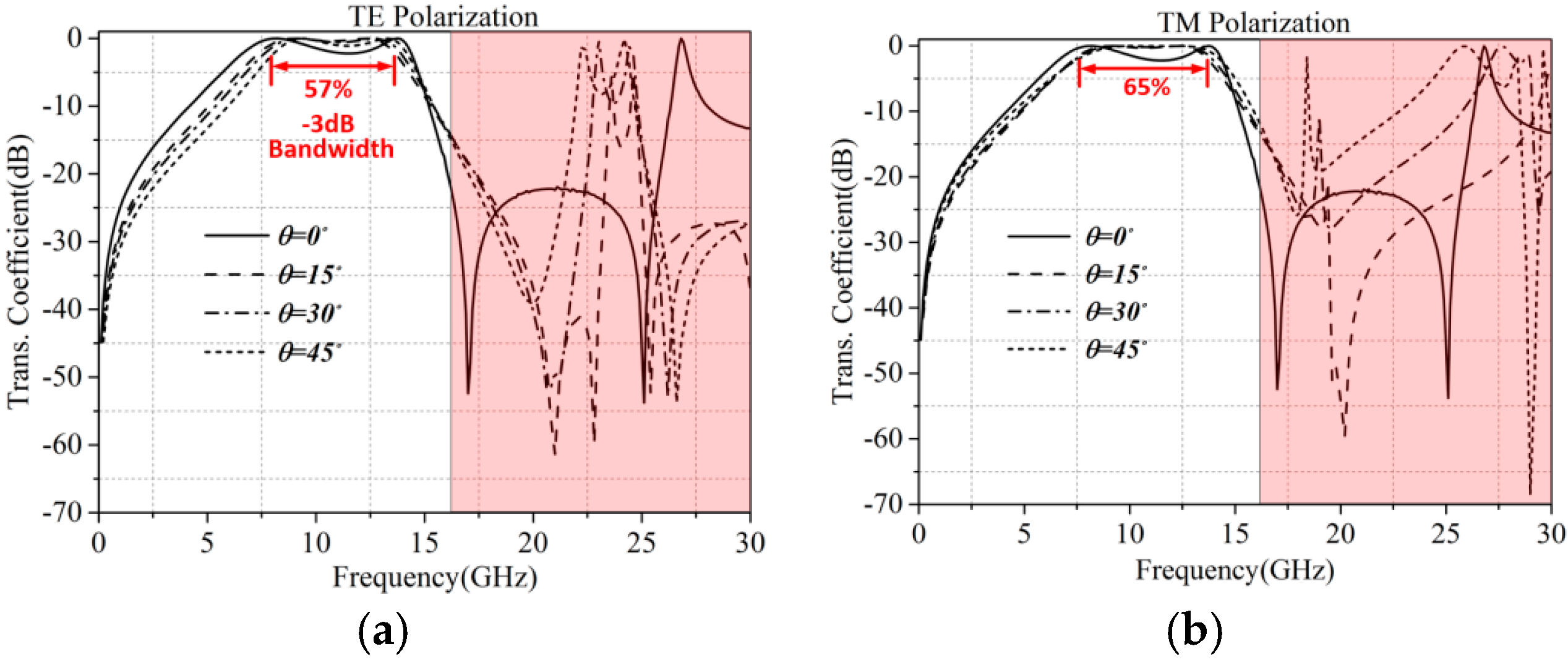
Next, the designed harmonic suppression FSMSE can be integrated with the aforementioned non-resonant patch-grid FSS and the resonant complementary loop FSS, respectively, as shown in Figure 8 and Figure 9. The air spacing h1 between the two original FSSs and the HS-FSMSE was also optimized using circuit analysis where the two types of FSSs are equivalent to band-pass circuits whose lumped elements can also be extracted by bisquare fitting algorithm. When h1 is 3 mm, the harmonic suppression feature can perfectly be achieved without deteriorating the operating frequency of the pass band. Figure 10 shows the transmission coefficient of non-resonant patch-grid FSS with HS-FSMSE for different incidence angles with TE and TM polarizations. It can be seen that the high-order harmonic waves can be suppressed below −40 dB after integrating with HS-FSMSE structure. Similarly, Figure 11 depicts the transmission coefficient of the resonant complementary loop FSS with HS-FSMSE for different incidence angles with TE and TM polarizations. The results show that the high-order harmonic waves can also be well suppressed even with the strong resonant behavior. In the meantime, we can see that the two different types of FSSs with same HS-FSMSE own good polarization and angle stabilities. It can be seen that the FSS with narrower bandwidth will be less affected after HS-FSMSE is added. Hence, cascading HS-FSMSE layers to suppress spurious transmission of band pass FSS filters could be used for the applications which needs relatively narrow pass band.
It is worth pointing out that the unit cell size of the patch-grid FSS and the complementary loop FSS are different. The patch-grid FSS is sub-wavelength structure whose period is only 6.6 mm, and the complementary loop is a conventional resonant structure whose period is 10 mm. For two different FSSs, the unit cell size of the harmonic suppression FSMSE is the same as 3.3 mm. As a result, when the HS-FSMSE is integrated with the patch-grid FSS, one unit corresponds to 2 2 HS-FSMSEs. And for the resonant complementary loop FSS, one unit corresponds to 3 3 HS-FSMSEs, as shown in Figure 8 and Figure 10, respectively. In this case, the different implementations show the transplantability of the HS-FSMSE.
3. Experimental Verification
In this section, a prototype of the patch-grid FSS integrating with HS-FSMSE has been fabricated, as shown in Figure 12. The fabricated prototype has five layers of metal structure printed on four substrates with dielectric constant and the loss tangent of 0.003. The layers are separated by air with plastic screws. The total size of the fabricated FSS is 235 235 7 mm. The air spacing is 3 and 2, respectively. Since the dimension of the fabricated FSS is relatively small especially in the far-field environment which will make the diffraction becomes strong, we use the two-port method in the near-field region to measure the transmission feature of FSS. In the measurement, we measured the transmission and reflection characteristics of the two horns measurement system without FSMSE for calibration. The near field coupling effect can be eliminated. For frequency selective surfaces, the features do not vary with different kinds of electromagnetic wave. The plane wave setup in the simulation is mean to model the far-field environment. Since we have removed the near-field coupling effect, the measurement results could be equal to the theoretical model when the plane wave is incident on the FSS.
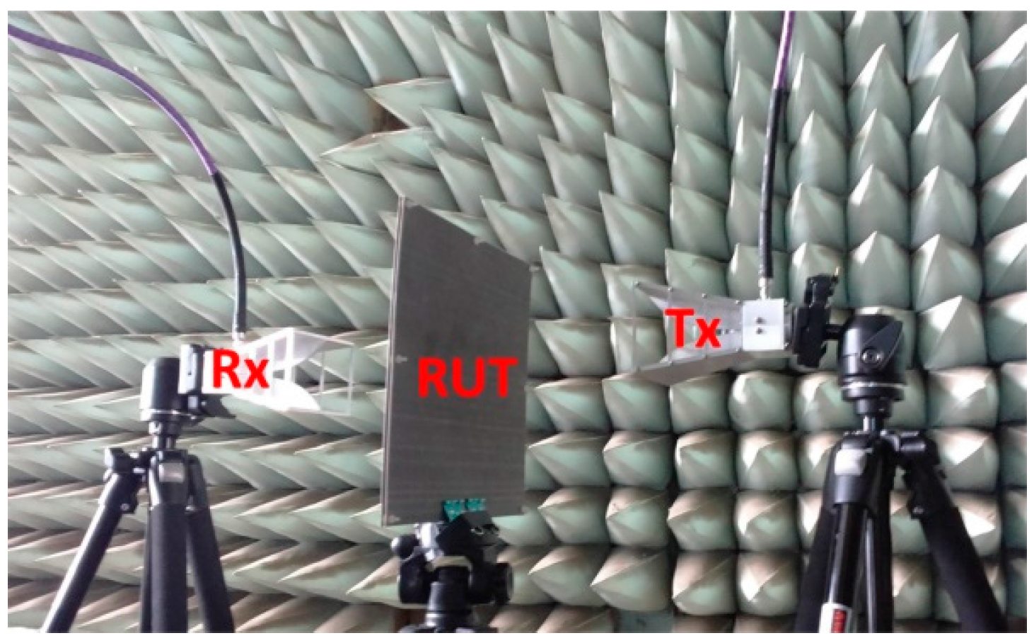
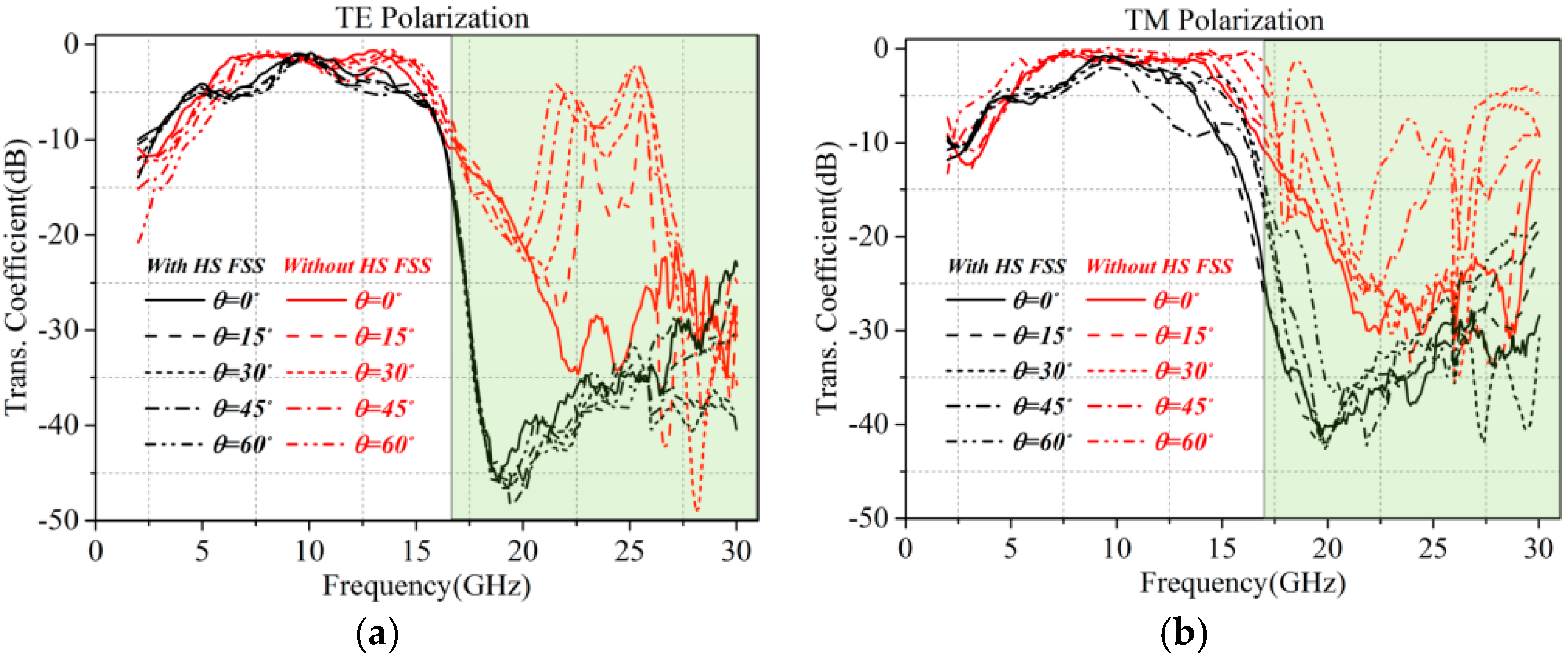
Experiments were performed by using three pairs of transmitting and receiving horn antennas that can cover different frequency ranges from 2 to 30 GHz. In these measurements, the broadband horns (2–18 GHz), K-band (18–26.5 GHz) horns and Ka-band (26.5–30 GHz) horns were used to measure the transmission coefficients of the fabricated FSMS. The system configuration for the measurement is shown in Figure 13, where Tx and Rx stand for the transmitting and receiving antennas, respectively, and RUT represents the fabricated FSS which was tested in the microwave chamber. The distance from Rx to FSS is 100 mm and from Tx to RUT is also 100 mm. It is worth noting that the center of RUT should be in direct line with that of Rx and Tx. The Anritsu MS46322A (E, Anritsu, Atsugi-shi, Kanagawa, Japan, 2015) 40 GHz vector network analyzer is used to measure the transmission characteristics. And we also measured the transmission and reflection characteristics of only two horns system without the FSS for calibration. Figure 14 shows the comparison of measured transmission coefficients between the original patch-grid FSS with and without HS-FSMSE. It can be seen that the designed HS-FSMSE effectively removes the undesired spurious transmission windows of the original patch-grid FSS. Even if the oblique incident angle is as large as 60 degree, the HS-FSMSE still works well. The measured frequency responses after calibration agree well with the simulated ones. The contribution of the proposed HS-FSMSE for the complementary resonant loop FSS is almost the same.
4. Conclusions
A transplantable harmonic suppression FSMSE is designed and analyzed, which can be applied to arbitrary FSSs operating at the same frequency band. And the designed HS-FSMSE was integrated with two kinds of different FSSs: the sub-wavelength patch-grid FSS and the complementary resonant loop FSS. The simulation and measurement results show that the proposed HS-FSMSE can effectively remove the spurious transmission windows outside of the desired operation frequency range. Using the HS-FSMSE, the two FSSs operating at 10 GHz are free of high-order harmonic transmission bands up to 30 GHz without deteriorating the operating frequency of the pass band. The transplantable HS-FSMSE also shows good polarization and angle stabilities. The most essential cause of its flexibility lies in that the harmonic suppression FSMSE is designed independently from the original FSS. Additionally, the narrow band pass feature is taken in consideration when designing the harmonic suppression FSMSE. In other words, the design procedure of the original band pass FSS and harmonic suppression FSMSE are independent of one another. This makes the harmonic suppression FSMSE transplantable to different kinds of FSSs. What’s more, the period of the harmonic suppression FSMSE is less than 0.2 wavelengths at band pass operating frequency (In this paper, the period of the harmonic suppression FSMSE is 0.11 wavelengths at band pass operating frequency). The small period size could be used for arranging most of the band pass FSS directly without cutting out both the harmonic suppression FSMSE and the original FSS.
Acknowledgments
This work is supported by National Natural Science Foundation of China under Contract No. 51477126, and supported by Technology Explorer and Innovation Research Project, and Fundamental Research Funds for the Central Universities.
Author Contributions
All authors contributed substantially to the reported work. Na Kou conceived the idea of transplantable high-order harmonic suppression frequency selective surfaces and performed the simulations and experiments; Haixia Liu provided the main instructions of experiments; Long Li provided the main instructions of this study and revised the paper.
Conflicts of Interest
The authors declare no conflict of interest.
References
- Munk, B.A. Frequency Selective Surfaces: Theory and Design; Wiley-Interscience: Hoboken, NJ, USA, 2000. [Google Scholar]
- Munk, B.A. Frequency-Selective Surface and Grid Array; Wiley: Hoboken, NJ, USA, 1995. [Google Scholar]
- Costa, F.; Monorchio, A. A Frequency selective radome with wideband absorbing properties. IEEE Trans. Antennas Propag. 2012, 60, 2740–2747. [Google Scholar] [CrossRef]
- Sievenpiper, D.; Zhang, L.; Broas, R.F.J.; Alexopolous, N.G.; Yablonovitch, E. High-impedance electromagnetic surfaces with a forbidden frequency band. IEEE Trans. Microw. Theory Tech. 1999, 47, 2059–2074. [Google Scholar] [CrossRef]
- Lin, Y.; Wang, L.; Gao, J.; Lu, Y.; Jiang, S.; Zeng, W. Broadband working-waveband-tunable polarization converter based on anisotropic metasurface. Appl. Phys. Express 2017, 10, 032001. [Google Scholar] [CrossRef]
- Chakravarty, S.; Mittra, R.; Williams, N.R. On the application of the microgenetic algorithm to the design of broad-band microwave absorbers comprising frequency-selective surfaces embedded in multilayered dielectric media. IEEE Trans. Microw. Theory Tech. 2001, 49, 1050–1059. [Google Scholar] [CrossRef]
- Al-Joumayly, M.; Behdad, N. A Generalized method for synthesizing low-profile, band-pass frequency selective surfaces with non-resonant constituting elements. IEEE Trans. Antennas Propag. 2010, 58, 4033–4041. [Google Scholar] [CrossRef]
- Abadi, S.M.A.M.H.; Li, M.; Behdad, N. Harmonic-suppressed miniaturized-element frequency selective surfaces with higher order bandpass responses. IEEE Trans. Antennas Propag. 2014, 62, 2562–2571. [Google Scholar] [CrossRef]
- Pozar, D.M. Microwave Engineering, 3rd ed.; John Wiley & Sons: Hoboken, NJ, USA, 2004. [Google Scholar]
- Parker, E.A.; Hamdy, S.M.A.; Langley, R.J. Arrays of concentric rings as frequency selective surfaces. Electron. Lett. 1981, 17, 880–881. [Google Scholar] [CrossRef]
- Overview of Curve Fitting Models and Methods in LabVIEW. Available online: http: //www.ni.com/white-paper/6954/en/ (accessed on 31 July 2009).
Figure 1.
(a) Subwavelength multilayer patch and grid frequency selective surface (FSS), (b) resonant complementary loop FSS (The grey represents substrates, the yellow and orange parts represent metal).
Figure 1.
(a) Subwavelength multilayer patch and grid frequency selective surface (FSS), (b) resonant complementary loop FSS (The grey represents substrates, the yellow and orange parts represent metal).
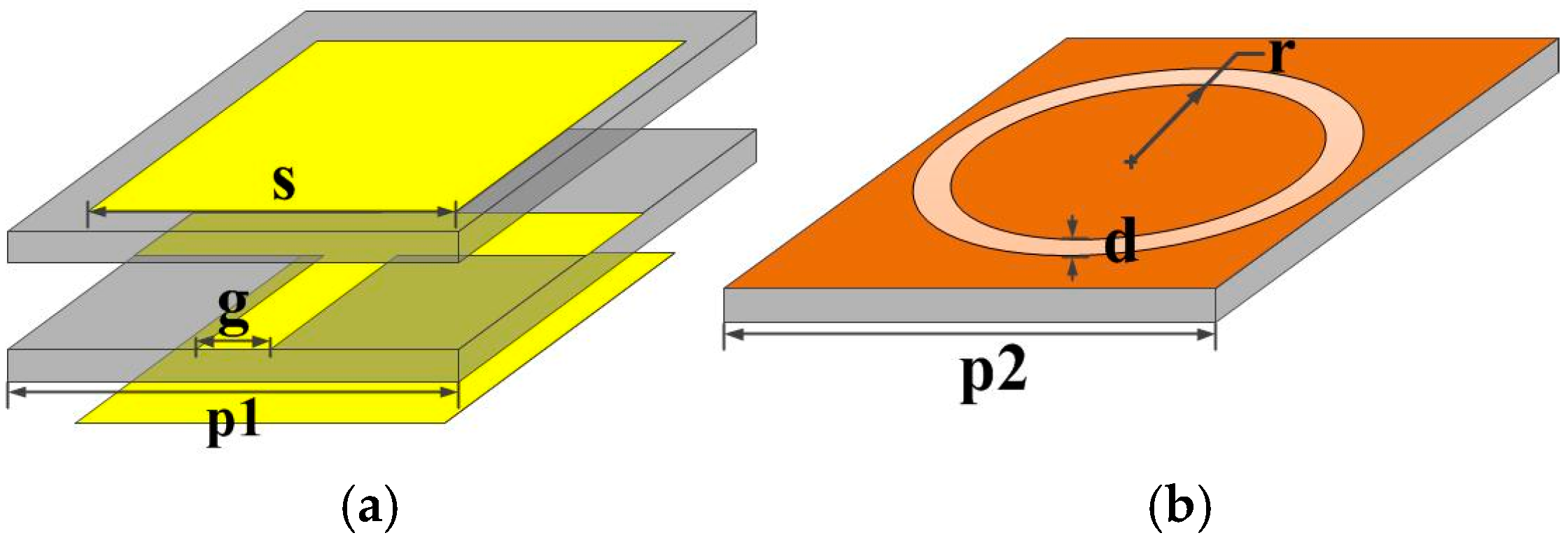
Figure 2.
Transmission coefficient characteristics for oblique incidences on the non-resonant FSS for (a) Transverse Electric (TE) polarization and (b) Transverse Magnetic (TM) polarization (The red shadow represents harmonic transmission bands).
Figure 2.
Transmission coefficient characteristics for oblique incidences on the non-resonant FSS for (a) Transverse Electric (TE) polarization and (b) Transverse Magnetic (TM) polarization (The red shadow represents harmonic transmission bands).

Figure 3.
Transmission coefficient characteristics for oblique incidences on the resonant complementary loop FSS for (a) TE polarization and (b) TM polarization (The red shadow represents harmonic transmission bands).
Figure 3.
Transmission coefficient characteristics for oblique incidences on the resonant complementary loop FSS for (a) TE polarization and (b) TM polarization (The red shadow represents harmonic transmission bands).
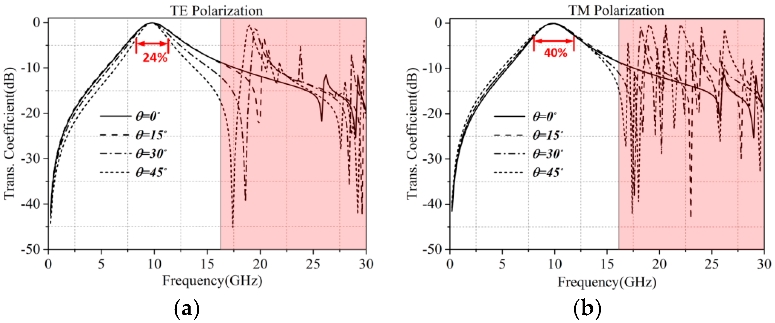
Figure 4.
A 3D topology of harmonic suppression frequency selective metasurface element (FSMSE) (The blue part represents metal and the grey represents substrates).
Figure 4.
A 3D topology of harmonic suppression frequency selective metasurface element (FSMSE) (The blue part represents metal and the grey represents substrates).

Figure 5.
The equivalent circuit of harmonic suppression metasurface element.

Figure 6.
Comparison of transmission coefficients of the full-wave simulation and equivalent circuits of the harmonic suppression FSMSE.
Figure 6.
Comparison of transmission coefficients of the full-wave simulation and equivalent circuits of the harmonic suppression FSMSE.

Figure 7.
Transmission coefficients for oblique incidences with different angles on the harmonic suppression (HS) FSMSE, (a) TE polarization and (b) TM polarization.
Figure 7.
Transmission coefficients for oblique incidences with different angles on the harmonic suppression (HS) FSMSE, (a) TE polarization and (b) TM polarization.

Figure 8.
Multilayer patch-grid FSS integrating with HS-FSMSE (The yellow and blue parts represent metal, the grey represents substrates).
Figure 8.
Multilayer patch-grid FSS integrating with HS-FSMSE (The yellow and blue parts represent metal, the grey represents substrates).

Figure 9.
Complementary loop FSS integrating with HS-FSMSE (The orange and blue parts represent metal, the grey represents substrates).
Figure 9.
Complementary loop FSS integrating with HS-FSMSE (The orange and blue parts represent metal, the grey represents substrates).

Figure 10.
Transmission coefficient for oblique incidences with different angles on the multilayer patch-grid FSS with HF-FSMSE, (a) TE polarization and (b) TM polarization (The green shadow represents suppressed harmonic transmission bands).
Figure 10.
Transmission coefficient for oblique incidences with different angles on the multilayer patch-grid FSS with HF-FSMSE, (a) TE polarization and (b) TM polarization (The green shadow represents suppressed harmonic transmission bands).

Figure 11.
Transmission coefficient for oblique incidences with different angles on the complementary loop FSS with HF-FSMSE, (a) TE polarization and (b) TM polarization (The green shadow represents suppressed harmonic transmission bands).
Figure 11.
Transmission coefficient for oblique incidences with different angles on the complementary loop FSS with HF-FSMSE, (a) TE polarization and (b) TM polarization (The green shadow represents suppressed harmonic transmission bands).

Figure 12.
Geometry of the fabricated multilayer patch-grid FSS integrating with HS-FSMSE, (a) total view, (b) patch layer, (c) grid structure layer, (d,e) harmonic suppression FSMSE layers.
Figure 12.
Geometry of the fabricated multilayer patch-grid FSS integrating with HS-FSMSE, (a) total view, (b) patch layer, (c) grid structure layer, (d,e) harmonic suppression FSMSE layers.
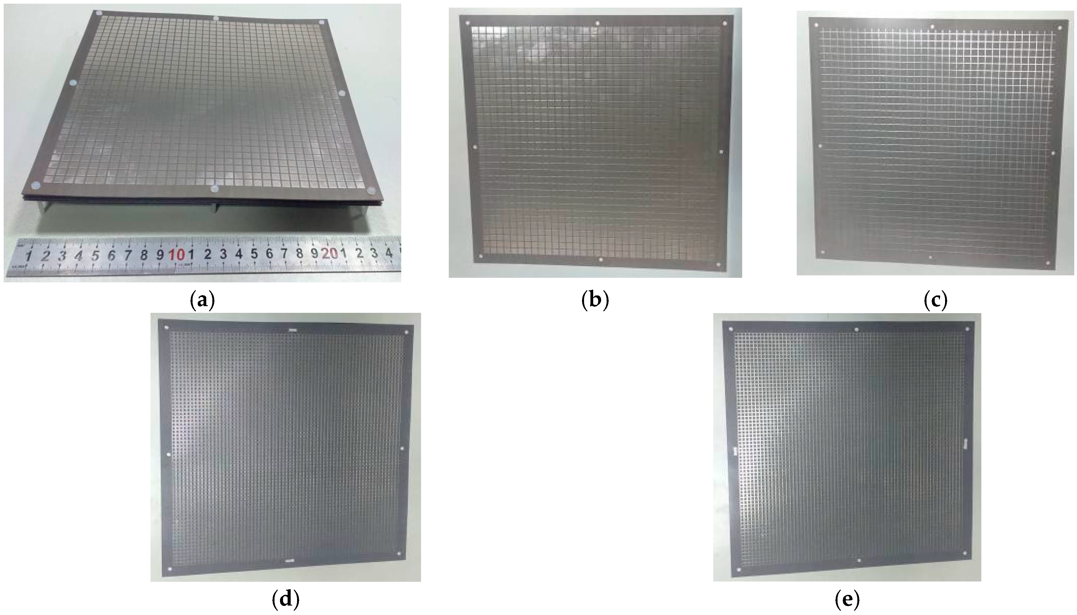
Figure 13.
Measurement system setup for the FSS in the near field region.

Figure 14.
Comparison of the measured transmission coefficients between the non-resonant FSS with HS-FSMSE and without HS-FSMSE for oblique incidence angles for the (a) TE polarization and (b) TM polarization (The green shadow represents suppressed harmonic transmission bands).
Figure 14.
Comparison of the measured transmission coefficients between the non-resonant FSS with HS-FSMSE and without HS-FSMSE for oblique incidence angles for the (a) TE polarization and (b) TM polarization (The green shadow represents suppressed harmonic transmission bands).


Table 1.
Parameters of the frequency selective surfaces (FSSs) shown in Figure 1.
Table 1.
Parameters of the frequency selective surfaces (FSSs) shown in Figure 1.
| Parameters | s | g | p1 | r | d | p2 |
|---|---|---|---|---|---|---|
| mm | 5.5 | 0.5 | 6.6 | 4.3 | 0.5 | 10 |
Table 2.
Parameters of the FSSs shown in Figure 4.
Table 2.
Parameters of the FSSs shown in Figure 4.
| Parameters | a | b | w | p | t | h |
|---|---|---|---|---|---|---|
| mm | 3 | 2.8 | 0.2 | 3.25 | 0.5 | 2 |
© 2017 by the authors. Licensee MDPI, Basel, Switzerland. This article is an open access article distributed under the terms and conditions of the Creative Commons Attribution (CC BY) license (http://creativecommons.org/licenses/by/4.0/).
Share and Cite
MDPI and ACS Style
Kou, N.; Liu, H.; Li, L. A Transplantable Frequency Selective Metasurface for High-Order Harmonic Suppression. Appl. Sci. 2017, 7, 1240. https://doi.org/10.3390/app7121240
AMA Style
Kou N, Liu H, Li L. A Transplantable Frequency Selective Metasurface for High-Order Harmonic Suppression. Applied Sciences. 2017; 7(12):1240. https://doi.org/10.3390/app7121240
Chicago/Turabian StyleKou, Na, Haixia Liu, and Long Li. 2017. "A Transplantable Frequency Selective Metasurface for High-Order Harmonic Suppression" Applied Sciences 7, no. 12: 1240. https://doi.org/10.3390/app7121240
Note that from the first issue of 2016, this journal uses article numbers instead of page numbers. See further details here.