1. Introduction
With the application of intelligent technology, the demands for low-carbon living, and the driving forces of market regulation and government policy, the traditional power system is currently facing a significant transformation towards the smart grid system, for which the main features include self-healing and being of high quality, allowing various forms of power generation, and improving power market and asset optimization [
1,
2]. Advanced information technology is the key to the smart grid, and therefore bottlenecks located in the information collection, transmission, processing and sharing of the traditional power grid should be solved [
3]. It is necessary to address the technology of the sensing measurement systems, data representation and storage systems, analysis and decision systems, control and execution systems, and so on [
4]. The computing and communication processes are deeply embedded in the power physical process, which interact closely with physical process and bring new capabilities. Therefore, the smart grid can be studied from the perspective of cyber-physical integration. With the application of 3C technology (i.e., calculation, communication, and control), there is an interaction of power flow and information flow in a considerable number of power services. Therefore, the power system has transformed into an open, interconnected, stable, and self-consistent system, namely the cyber-physical power system (CPPS) [
5,
6,
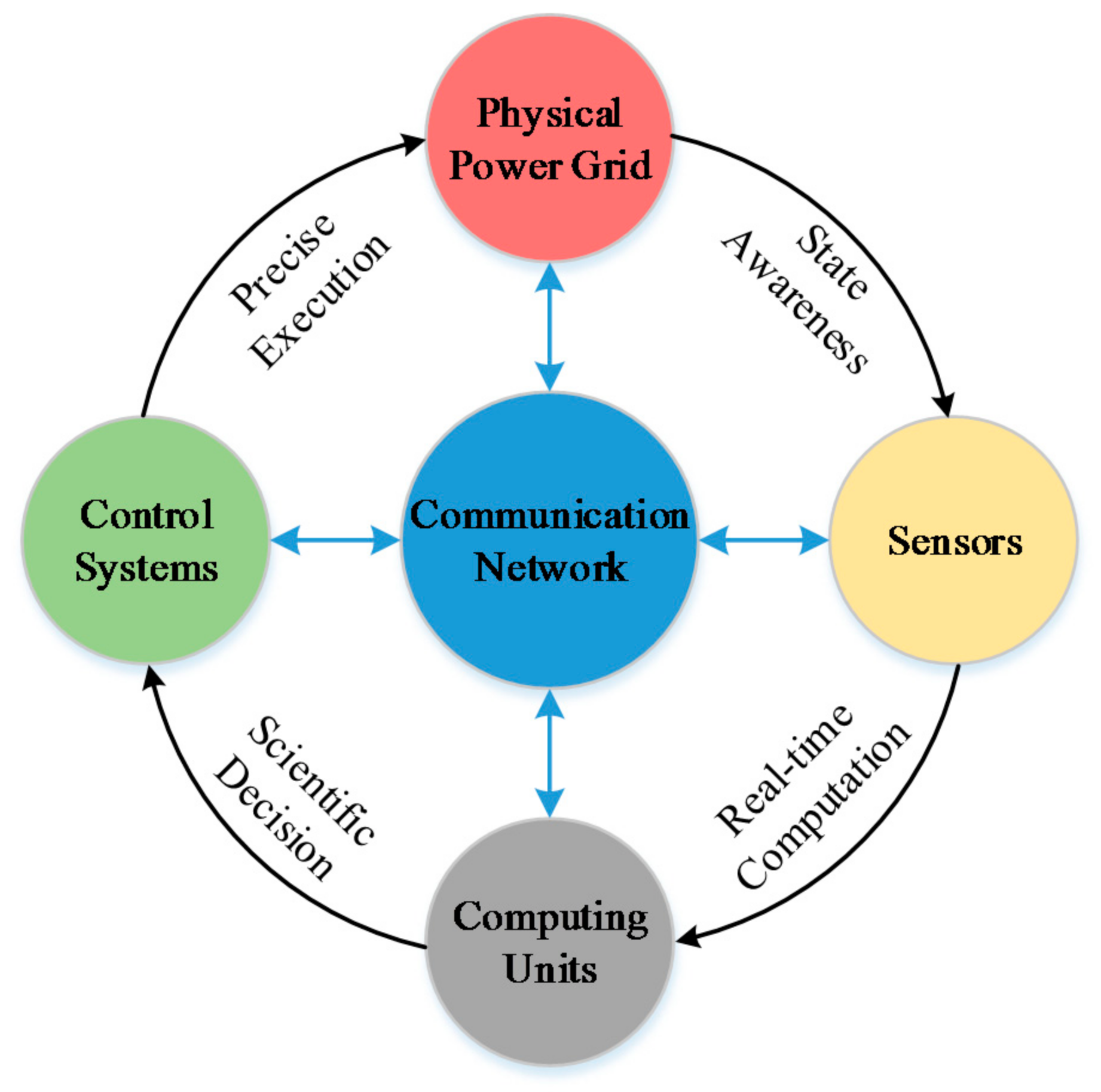
7]. CPPS can not only obtain data from the environment, fuse data, and extract effective information, but also act on the environment through the effector. The key connotation of CPPS is the wide interconnection and integration of the physical power grid, sensor network, computing units, communication network, and control modules, through which the power system operates in a reliable, efficient, and real-time synergetic mode [
8,
9].
The application of information and communication technologies (ICT) not only increases the intelligence level, but also brings control complexity to the power system operation. The power system load control is used as an example. In the traditional operation mode, the load usually plays the role of a controlled object, while in the CPPS environment, with access to intelligent terminal equipment and the construction of advanced measurement infrastructure, the system has better observability and controllability of the load. On one hand, from the perspective of the user, the insertion of active load gains a better ability for information collection and demand response. On the other hand, from the perspective of a large power grid, the wide installation of intelligent controllers provides better technical support for resource configuration, and security and stability control, etc. However, the wide area information also has higher requirements for the reliability and speed of communication. The delay, error, or disruption of communication may cause the system to become unable to respond to disturbances in time, or make the controller fail to take effective measures, especially under a state of emergency. As a result, the global optimal coordinated control of an interconnected power grid cannot be guaranteed.
The key of CPPS research is to explore the mechanism of influence of the information field on the primary power system. In traditional power system research, the whole system is divided into several independent modules according to function, whose dynamic characteristics are described by differential algebraic equations. However, CPPS contains many items of distributed computing and control equipment where modules with various mechanisms and forms are deeply interconnected by the information communication system. Therefore, the original attributes of the power, communication, and control devices are influenced and changed by each other, which requires research within a common framework. Compared with the independent analysis of these attributes, unified modeling can more effectively describe the internal connection among the multilayer physical and information objects [
10,
11,
12]. In order to analyze the interaction characteristics among the physical environment, communication environment, and control flow, typical CPPS services and applications are simulated and analyzed [
13]. Mainstream research interests include the contradiction between fast response demand and limited network bandwidth, the interaction between distributed computing modules and the centralized control center, and the interactive optimization algorithm among power sources, networks, and loads [
14].
To analyze the impact of communication quality on the power grid operation, there must be guarantees of the smooth interconnection and intercommunication between the power grid and communication grid. The key lies in how to unify the information system and power system fully. The modeling, analysis, and control methods matching CPPS are essential in the design and guidelines of specific power system applications. However, there is a gap in the traditional research on the power and information systems. The power system is a time-varying continuous system where the power flow information is calculated by differential algebraic equations; while the information system is discrete and event-driven, where the key event point can be derived by the finite state machine. Therefore, the split representation features between both systems hinder the unified theoretical modeling of CPPS, which remains to be further researched.
Before the breakthroughs of theoretical research on CPPS, software simulations based on the prototype feature of CPPS played an ever-increasing role in simulation, testing, and verification support of theoretical and practical research [
15]. Therefore, a platform that simulates the multi-state and multi-fineness characteristics of CPPS needs to be established. Typical power system simulators apply the discrete step to approximate the continuous process, while typical information system simulators use the discrete-state model to describe the network behavior. There is no unified software simulating both systems simultaneously. Instead, the co-simulation scheme first simulates power and communication situation alone, and then realizes the data sharing and collaborative work through an interactive interface. This creates a combination of several simulators, which allows participants to interact, coordinate, and cooperate with each other, while conserving their own advantages. Its easy implementation and high reliability make co-simulation a feasible scheme. In recent years, with increasing attention and support of CPPS, several co-simulation tools have been developed, and are summarized in detail in
Section 2.
The focus of current co-simulation platforms is the data synchronization and coordinated control between both simulators. Based on the simulation speed, the data synchronization methods include real-time and non-real-time methods; and according to the location of control unit, the control methods include internal control and independent control. The main applications of the current platforms are to analyze the impact of the parameters (e.g., delay, throughput, bit error rate of the power communication protocol) on the power service operation. Due to the lack of real-time performance and model accuracy in a digital simulation platform, the process of control loop and the time sequence of data interaction in CPPS cannot be accurately constructed and analyzed. Therefore, a real-time hardware-in-the-loop platform was put forward in our paper, where real-time simulators were utilized to make up for the simulation speed, and hardware control devices were utilized to make up for the model authenticity. As a result, a complete, closed-loop and credible data flow in CPPS was built to simulate and verify the real-world power-communication interaction case.
This paper is mainly dedicated to the design and application of CPPS co-simulation. First, through the analysis of the interaction mechanism of power flow and information flow, the corresponding modeling, analysis, and control methods were put forward. Then, the framework of the CPPS real-time hardware-in-the-loop co-simulation platform was introduced where the software simulation and hardware insertion were combined to realize the closed simulation loop. The digital part was based on the Real-Time Laboratory (RT-LAB) and OPNET, while the hardware part was developed by the advanced RISC machines (ARM) processor. Moreover, to verify the proposed platform, a case study of wide area load control was performed. The time delay of each component was decomposed into several parts to analyze their influencing factors. Finally, by comparing the different implementation effects resulting from the various link parameters, data attributes, control strategies, and device statuses, the system protection performance of CPPS was validated.
The original contributions of this work include: (1) the combination of digital simulation and analog simulation to achieve great modeling convenience, low development cost, high simulation speed, and close practicality; (2) the application of a hardware simulation into the control process to credibly reflect the internal control and external interaction characteristics; and (3) that all simulators could run in the real-time environment, which can make simulation close to the real-world physical process.
The rest of the paper is organized as follows.
Section 2 introduces the current research into CPPS co-simulation platforms.
Section 3 specifies the structure of the proposed hardware-in-the-loop platform.
Section 4 demonstrates the simulation on a wide area load control case, and
Section 5 concludes the paper.
3. Establishment of CPPS Real-Time Hardware-in-the-Loop Co-Simulation Platform
In current digital co-simulation, the control module is usually developed by software in an independent host, transmitting digital control signals to other simulators through Ethernet. The advantages of digital simulation are the fast simulation speed, low cost, convenient parameter adjustment, and non-restricted system scale. However, it is short of the intuition of physical concepts. For equipment with complex structures and internal interrelationships, a mathematical model may be too difficult to establish. Therefore, a control module developed by physical devices was applied in the platform, forming a hardware-in-the-loop simulation. In addition to the digital power flow and information flow, the analog control flow can reflect real-world control properties. The mixed-signal platform can take advantage of both simulation types, ensuring the intuition, universality, flexibility, and integrity of the co-simulation. On the whole, the proposed co-simulation in our research possessed the following characteristics: distributed type, real-time, and hardware-in-the-loop.
3.1. Simulation Requirements and Overall Structure for the Platform
One of the most important features of a CPPS is that complete and detailed information can be obtained by means of advanced sensor and high-speed communication networks. This includes various types of measured data such as frequency and voltage collected by the phasor measurement unit (PMU) and remote terminal unit (RTU), and external data such as meteorological information and intelligent load information. Plenty of information is conveyed to the control center to support monitoring, regulation, and protection.
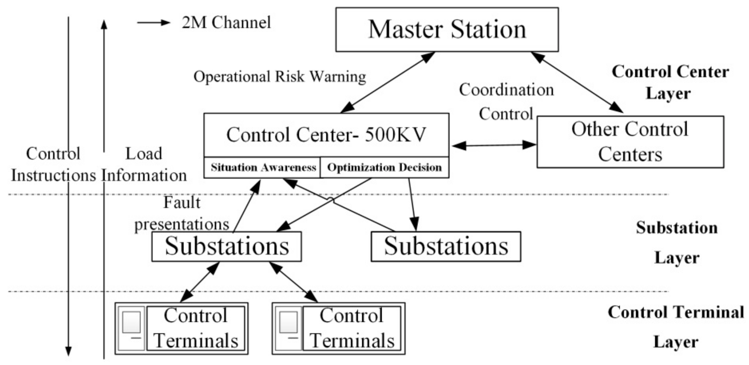
To investigate the interactive coupling characteristics between power flow and information flow, an accurate wide area load control case in the source–network–load system was put forward that can promote wide area protection effects. However, there is currently no related research on this kind of scheme. In a traditional power system, the source follows the change of load in one way. The source–network–load system is a flexible system where the power supply, transmission network, and intelligent load respond to and reserve each other. The status information of three layers is gathered to obtain the optimal control strategy, which requires fast and accurate awareness of multi-layer information. As shown in
Figure 2, the type and value of load terminal information should be accurately and rapidly informed by the control layer. When a security risk occurs in the system, an optimal load shedding strategy is executed according to the priority of load to maintain the voltage and frequency stability of the grid. Therefore, this kind of power service demands that the power simulator can support the real-time simulation of a large scale network, and an information simulator can realize the physical and logical construction of control devices and a measurement terminal mapped to the power nodes. The communication network can support a special power communication protocol and real-time link simulation, which can transfer the load information and control instructions among the control center, control substation, and the terminal in a timely fashion as well as responding quickly to changes in the power grid situation.
Load information is gathered from the control terminals in the bottom layer to control centers in the top layer. According to the control strategy and algorithm, control instructions are generated by the control center and are issued by the control substation. This typical multi-level stability control service goes through the process of data acquisition, transmission, processing, transmission, and execution.
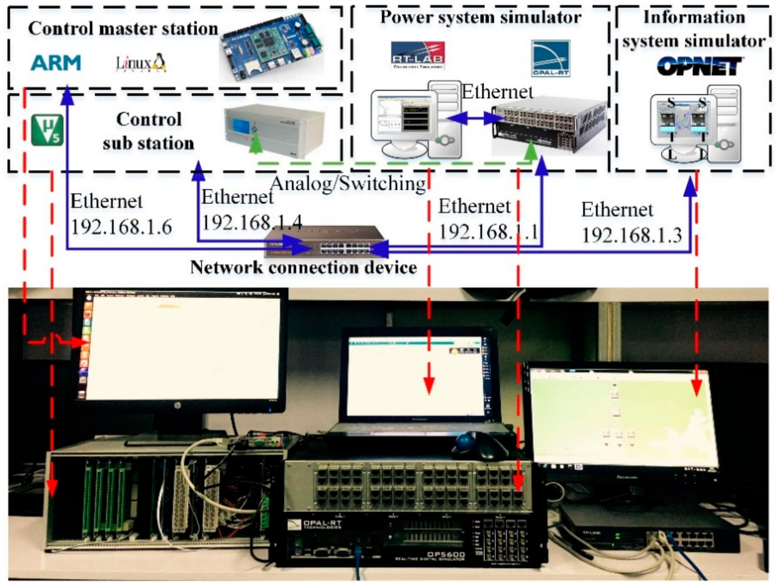
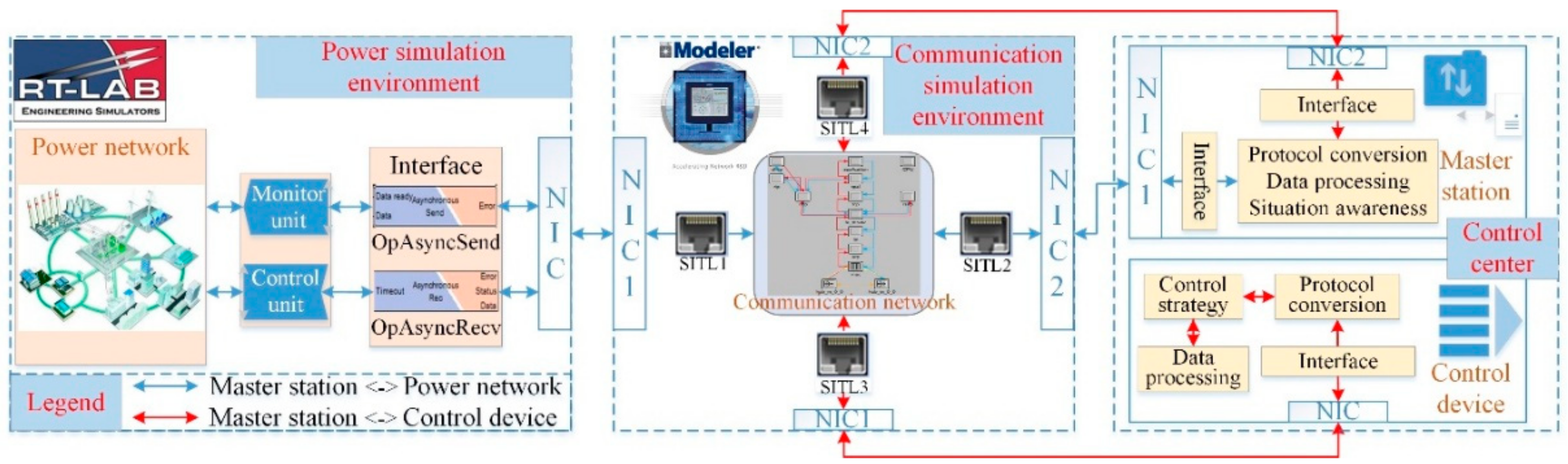
For data processing procedures among multiple data transmissions, an independent control module is established in the platform, which receives and handles data from the information simulator and can return control instructions. As shown in
Figure 3, a three-layer co-simulation platform was established, including a power system layer, communication network layer, and a control center layer. The power layer and communication layer were established by the digital simulators RT-LAB and OPNET, respectively, which are responsible for the real-time simulation of the power and communication environments. Meanwhile, the control center layer was established by hardware devices to simulate the control master station and control execution station, thus forming a closed control loop of the whole platform.
3.2. Modeling and Simulation of Power Physical System
The key to real-time power simulation is that the task can be decomposed by the distributing process and executed across a parallel infrastructure. Normal power system simulators are attached to a PC, which cannot satisfy the requirements of calculation speed. Considering the real-time requirements, there are two commercial specialized simulators to choose from: the Real-Time Digital Simulator (RTDS) (developed by RTDS Technologies, Winnipeg, MB, Canada) and RT-LAB (developed by OPAL-RT Technologies, Montréal, QC, Canada). In consideration of the relatively mature model library and cheap cost of RT-LAB, it was chosen as the real-time simulator of the power system.
Through full integration with MATLAB/Simulink (developed by MathWorks, Natick, MA, USA). RT-LAB is compatible with entire models of MATLAB/Simulink. Moreover, RT-LAB is equipped with several special model libraries like RT-events, RT-Drive, and ARTEMIS, which cover various power system situations including the electromagnetic transient simulation of a large-scale Alternating Current/Direct Current (AC/DC) power system, power grid planning and feasibility analysis, transient stability simulation of power system, and an integration test of flexible AC transmission systems (FACTs) and high voltage direct current transmission (HVDC) control systems.
RT-LAB provides the common models for interaction with exterior environments, which are as follows: the OpIPSocketCtrl module is responsible for data control, the OpAsyncRecv module is responsible for data reception, and the OpAsyncSend module is responsible for data sending. By employing these modules, RT-LAB can communicate with other simulators through the TCP/IP protocol.
3.3. Modeling and Simulation of Information Communication System
Mainstream information communication simulators can be divided into two types: commercial simulators represented by OPNET (developed by riverbed, San Francisco, CA, USA) and QualNet (developed by SCALABLE Network Technologies, Inc., Culver City, CA, USA), and open source simulators represented by NS2 and SSFNET. Generally, commercial simulators are expensive and relatively enclosed, while offering complex overall modeling support. In contrast, open-source simulators are freely available and are open source; however, their structure and function are simplified when compared with real-world situations. When it comes to the co-simulation of a CPPS, the following functions of communication network simulators are required: compatibility with hardware-in-the-loop, detailed modeling of the electric power communication network, and the real-time performance of the simulation. In consideration of these factors, the OPNET Modeler was chosen to model the information communication system in our research.
The OPNET Modeler is a discrete-event network simulator that analyzes and tests the performance of a communication network. Users can carry out high-fidelity modeling, scalable simulations, and detailed analysis through its three-layer modeling mechanism: network modeling, node modeling, and process modeling.
OPNET provides three ways to communicate with the exterior environment: high-level architecture (HLA), the external simulation access-application programming interface (ESA-API), and system-in-the-loop (SITL). Of these three methods, SITL is the most current and fastest way to map multiple physical network interfaces to different network addresses in the virtual network. Through this technology, OPNET and the exterior environment can be made into a unified entity. Therefore, SITL was chosen as the interface between OPNET and the other simulators.
3.4. Modeling and Simulation of Control Center
The co-simulation platform consisted of several independent simulation entities, which demanded different requirements in terms of of continuity, step accuracy, and driving mode. To make the information from one simulator compatible with that of another, it was necessary to apply a time synchronization strategy to ensure a unified simulation clock. For the hardware-in-the-loop simulation, the power and information devices were simulated by software to ensure the simulation speed and accessibility, while control devices were simulated by real-word devices to improve the simulation authenticity.
The physical control center was responsible for inhibiting the accident diffusion after fault. It was composed of the master station and the stability control devices. The master station was based on the ARM processor (developed by Acorn Co., Ltd., Cambridge, UK) running on a Linux system and developed in C language, which possesses extendibility and real-time performance. The master station is responsible for receiving the status information from the power grid and the control instructions from the stability control device, and dealing with the data processing, situational awareness, and synchronous interactive control. The master station kept monitoring the grid operation status through measurement units. After the fault, the master station compared fault type and location with the preset strategy table, selected the optimal strategy and sent the commands to the stability control devices. The master station consisted of four modules: (1) the protocol analysis module used for parsing the data packets from the measurement units and control devices; (2) the database module used for storing the real-time state of power grid; (3) the fault detection module used for detecting whether the system was faulty; and (4) the control module used for generating optimal control strategies after the fault. The stability control device was developed based on an embedded Linux system, which was responsible for receiving and implementing control commands from the master station into practice, and maintained the operation stability in the power system simulation. Therefore, the coordinated and consolidated control of distributed simulators could be reached.
3.5. Sequential Procedure and Control Logic of the Whole Platform
The key goals of the control loop were to realize the synchronization of different simulators, modules, or processes that participate in the co-simulation to ensure the timeliness and accuracy of message delivery, and achieve a combination of independent simulation and collaborative simulation according to demand. Therefore, the distributed simulation components could be coordinated in a unified environment with high interoperability and reusability.
The sequential procedure and control logic are shown in
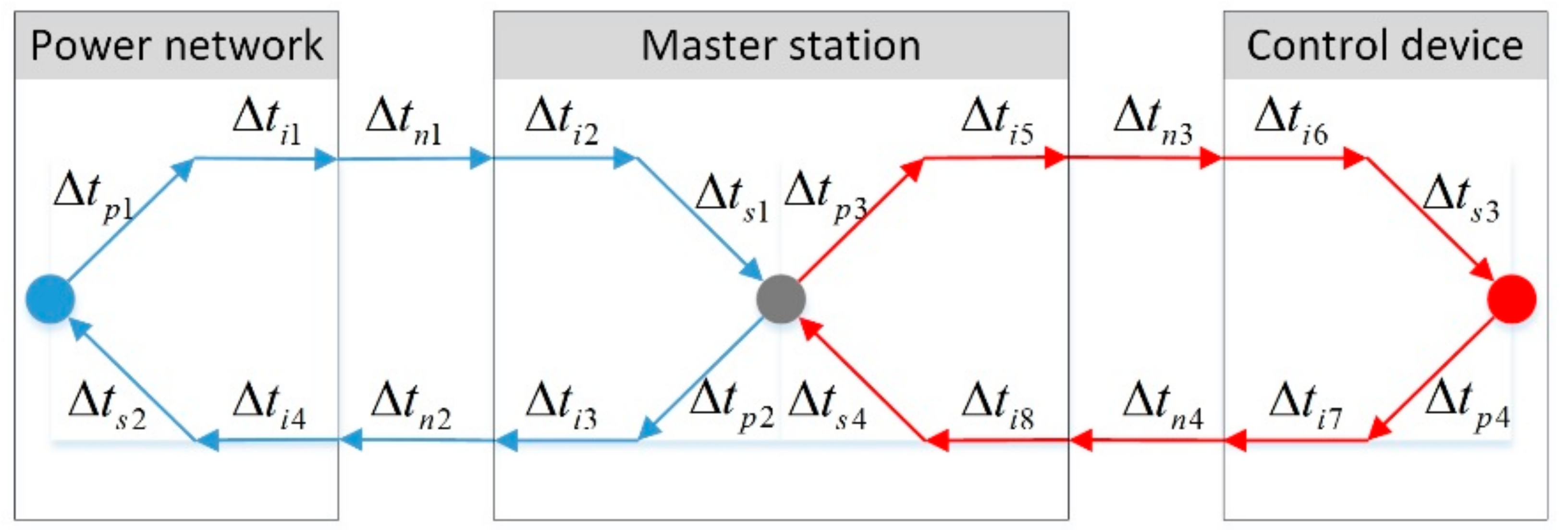
Figure 4 where the master station of the control center is the bridge that implements the control logic and time synchronization between both simulators. After receiving, analyzing, and handling data produced in the power model and communication model, the center generates control commands accordingly, and transfers them back to the power and communication environments. Power and information systems can be analyzed and controlled synchronously to meet the requirements of co-simulation.
Aiming at information acquisition and safety control service, the platform realizes the closed-loop data flow via two sets of communication networks where the blue line represents the data flow and the control flow between the power network and the master station system, and the red line represents the flow between the master station and the stability control device. In the wide area load control service researched in this paper, the most important feature in the system was its delay parameters. Therefore, the delay parameters of each part and their interactive influences were analyzed as shown in
Figure 5. For a complete closed-loop data flow, the total delay can be expressed as follows.
where
is the total delay of the platform, namely the time delay from the moment when the fault happens, to the moment when the control device acts. It is made up of several parts including the inherent delay
, sampling delay
, processing delay
, and network transmission delay
.The inherent delay
is related to the hardware parameters and the operating time inside each device, which is a constant value independent of data size. The sampling delay
is the time delay from the moment when packets arrive at the device to the moment when packets are received, and is subject to uniform distribution from 0 to the sampling period. The processing delay
is the analyzing and processing time of data, which is related to the packet format and the device’s computing ability. Moreover, it shows a positive correlation with the sampling rate. With the increase in sampling rate, the queuing time will rise, and the processing delay will also increase accordingly. The network transmission delay
is related to the parameters and congestion degree of the communication lines, which is simulated in the OPNET communication network.
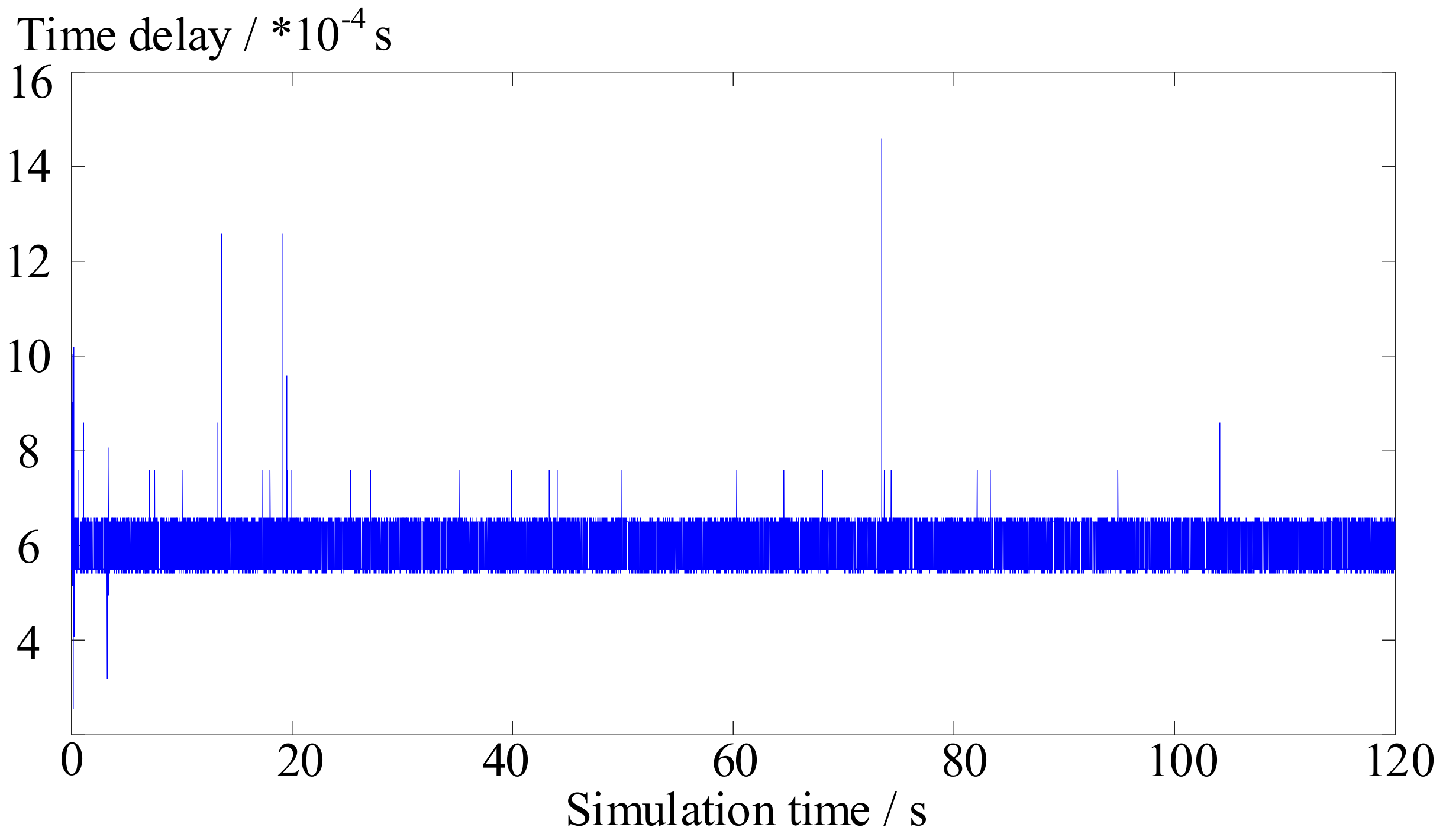
The measurement of inherent delay is described as follows. The other delay parameters are set to an ideal situation, and the time factor of simulation is set to 1 (i.e., equal to real-world time). Through a simple data sending and receiving process without data processing steps, a 120-s long simulation test was carried out as shown in
Figure 6. The average of inherent delay was 0.588 ms with little jitter, which was much smaller than the transmission delay of the communication service. Therefore, the simulation error resulting from inherent delay was limited without affecting the simulation accuracy.
4. Application Scenarios and Platform Extensions
4.1. Case Study: Wide Area Intelligent Load Control
An intelligent load case was proposed to verify the effectiveness of the proposed control scheme and platform. As an ultra-high voltage direct current transmission (UHVDC) receiving system, when several AC/DC lines are out of order at the same time, a huge power deficiency will cause a serious frequency decline in the power system. Therefore, through the quick load shedding function of the system, some interruptible loads should be cut within 650 ms to help recover system stability.
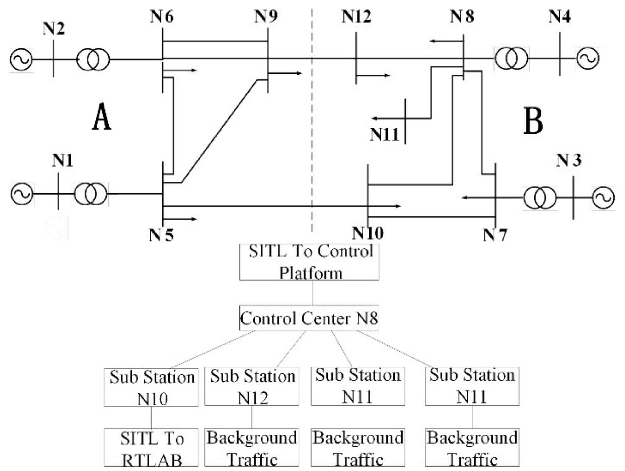
In RT-LAB, a power system of four generators and 12 nodes was set up as shown in
Figure 7, with a total load of 1446 MW. A short circuit fault caused a disconnection between both main lines, forming two isolated systems: districts A and B. Before the fault occurred, district B belonged to the receiving area, so the fault resulted in a power shortage and frequency decline, which required emergency control. N10 of district B contained 30 MW of intelligent interruptible load.
At the same time, the communication network between the control center and control subsystem was built in the OPNET. N8 was the control center, and was connected with the control platform through a SITL module, and N10 was the control substation, which was connected with RT-LAB by the other SITL module; the other control substations were connected with the background traffic generation modules to simulate the network data transmission. A 2M fiber channel was applied for the data transmission.
The implementation effects of the proposed CPPS real-time simulation platform were the focus in our research. The control strategy was as follows: the control center station sent the instructions to N10 when the frequency dropped to 49.6 Hz, which required 20 MW of intelligent load to be removed automatically.
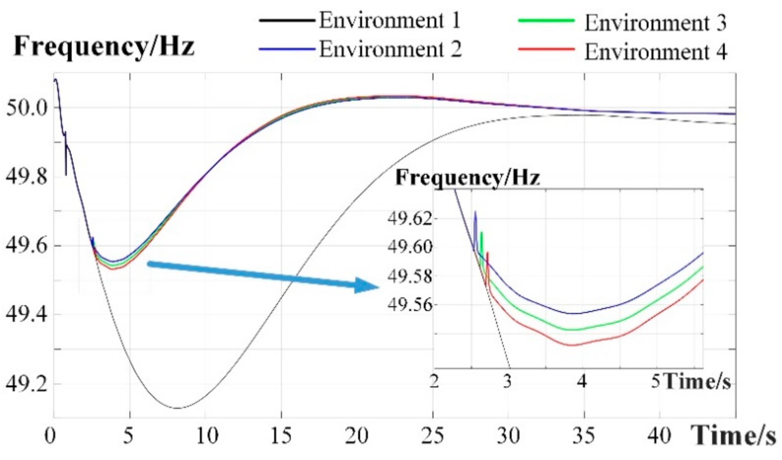
To verify the simulation effectiveness, basic Environments 1 and 2 were set. Environment 1 represented the case without control strategies, and Environment 2 was the ideal situation without time delay. Moreover, two additional kinds of communication environments were set for the information channel in OPNET. Environment 3 was the normal state. Each substation sent measurement and status information to the control center at a relatively low frequency, while receiving regulation information from the control center. Environment 4 was the emergency state (e.g., frequency fall). The data communication between the substations and control center surged, resulting in a long queuing delay at the control center, which led to a lag in data upload and instructions. All scenes were simulated and compared, and the frequency results after the fault are shown in
Figure 8.
Comparing the frequency curves of Environments 1 and 2, it was derived that the wide area intelligent load control strategy could remarkably alleviate the frequency decrease after faults, and increase the minimum frequency from 49.13 Hz to 49.53 Hz. Environments 3 and 4 were compared with Environment 2, which showed that the time transmission delay affected the action time of the control strategies. Due to the different link attributes and data rates of the communication links, Environments 3 and 4 caused a delay for 81.7 ms and 161.6 ms, respectively, and thus the minimum frequency dropped by 0.0112 Hz and 0.0243 Hz. Therefore, the proposed platform could accurately reflect the communication impact on the power service simulation results.
4.2. The Influence of Sampling Frequency on the Control Effect
To analyze the feature of partial delay, the whole time delay was resolved into intrinsic parts, and a variable-controlling approach was used to reveal the influence factors of each part. The factors of data sampling delay and network transmission delay were analyzed as follows:
The impact of sampling frequency on data sampling delay
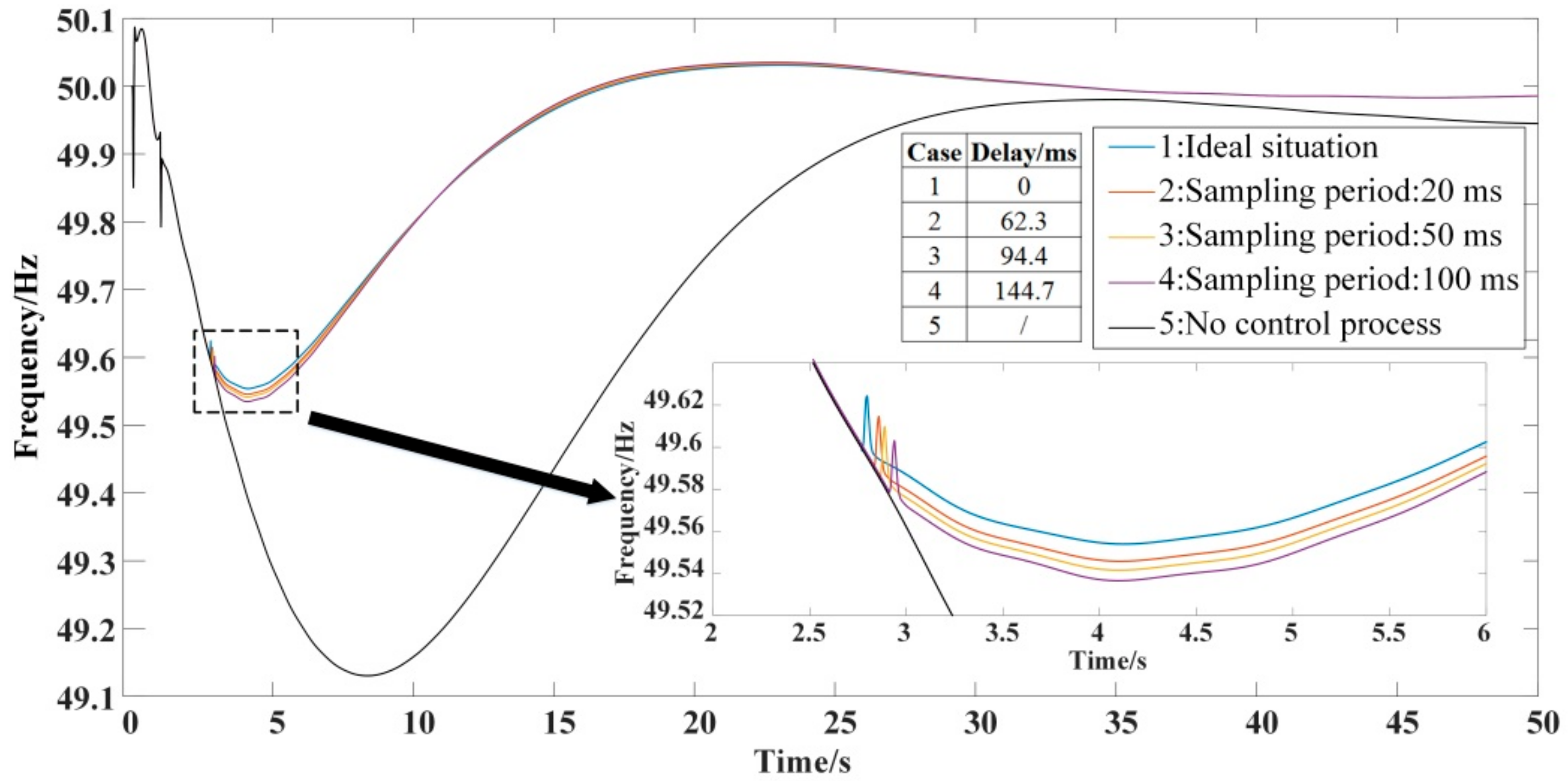
: In the physical device, the average sampling delay was decided by sampling frequency. The sampling frequency was set as a variable, and the communication delay was set as a constant. Three different sampling frequencies were set in Environments 2, 3, and 4 at 50 Hz, 20 Hz, and 10 Hz, respectively. While Environment 1 was ideal without delay, Environment 5 presented the case without the control strategy. Environment 1 was compared with Environments 2, 3, and 4. Due to the decreasing frequency, the data transmission delay increased gradually, and the control execution time lagged behind. As shown in
Figure 9, three different sampling frequencies caused a delay of 62.3 ms, 94.4 ms, and 144.7 ms, respectively, where the minimum frequency value was reduced by 0.0082 Hz, 0.0124 Hz, and 0.0191 Hz, respectively, when compared to the ideal situation.
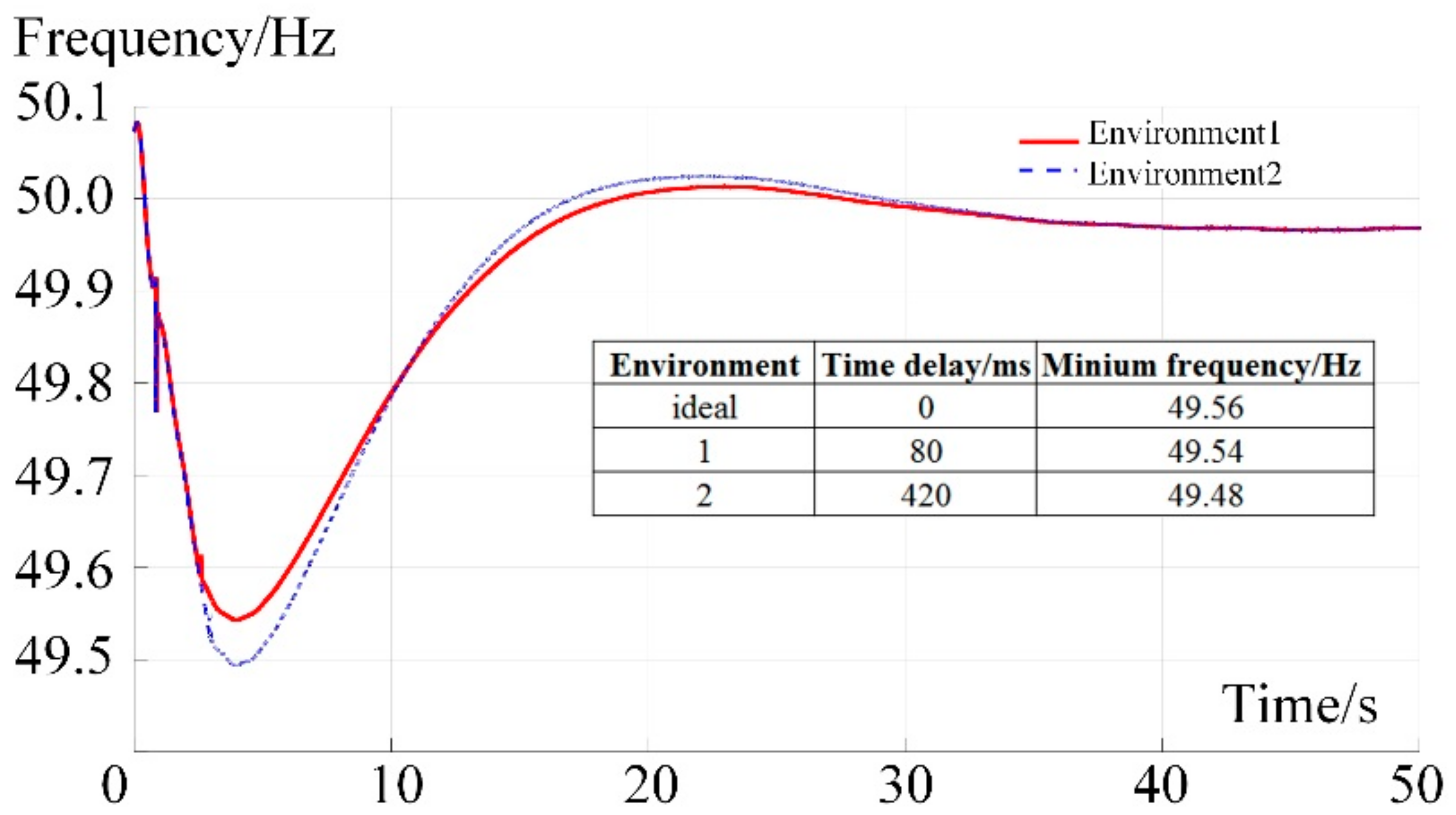
The impact of sampling frequency on network transmission delay
: Due to the limited capacity of the communication network, when the sampling frequency became higher, the queuing delay in the data transmission process, packet loss ratio, and bit error ratio increased, leading to blockages in the communication network. Therefore, the overall delay increased.
As shown in
Figure 10, two sets of network parameters were set: (1) the set where sampling frequency was 50 Hz (relatively low); and (2) the sampling set where frequency was 200 Hz (relatively high). Two sets of environment were simulated, and various sampling frequencies resulted in different delays. Compared to the ideal situation without delay, Environments 1 and 2 caused delays of 80 ms and 420 ms, respectively, and correspondingly the minimum frequency dropped by 0.02 Hz and 0.08 Hz, respectively.
4.3. The Importance and Extended Application Scenarios of Co-Simulation Platform
A CPPS increases the complexity and difficulty of the power system modeling process. Before the co-simulation method was proposed, researchers usually simplified the information process to analyze the performance of various services and applications. Through implanting the information module into power system software such as by adding a time-delay module in the measure loop and control loop, researchers could conduct CPPS analysis in a simple way. However, it is an approximate method without enough accuracy and reasonability for a particular CPPS service. Actually, the real-time delay is influenced by several factors such as packet formats, transmission rate, channel properties, and exterior environments, which cannot be reflected by the simplified simulation method. Moreover, real delay is influenced by the physical environment of a communication system, which presents a probability distribution instead of a fixed value. These are not reflected in the delay process of the traditional simulation. Instead, the co-simulation method provides a more intuitive and accurate way to reconstruct a CPPS environment. The time-delay attribute was the focus of this paper as a way to analyze how the communication environment influences the power system operation results. Actually, the influencing factor was not only in delay, but also included various attributes such as bit error and channel rotation, which are further research fields proposed by our team.
Besides the load control case analyzed in this paper, the proposed platform could also be applied to analyze other CPPS services such as the coordination control of distributed generation, the impact of communication failure on the security stability control, and cyber-attacks on the power system. The increasing integration of power service and information features pushes researchers to focus on the influence of information characteristics on power system control, analysis, and application.
5. Conclusions
The complex integration of power flow and information flow has presented challenges to the analysis of operational characteristics in CPPS. A hardware-in-the-loop co-simulation scheme of CPPS was put forward in this paper, and the effectiveness of the platform was demonstrated by a load control case. Through the formation and measurement of communication delay, the paper discusses the influence of real-time performance and reliability on the operation stability of CPPS, verifying that the platform has high processing capacity for data transmission and analysis performance. Moreover, the platform is applicable for multiple CPPS services such as coordination control and safety analysis.
The proposed platform possesses a distributed framework, which has a flexible structure and wide adaptability. Through block configuration utilizing its modular architecture, various kinds of simulation time scales and precision can be obtained in all distributed simulators. Moreover, through the integration of digital and hardware simulation, the advantages of both simulation types could be balanced to truly reflect the dynamic, static, and nonlinear characteristics of CPPS, and provide experimental support for the verification of the relevant CPPS theory.
With the large-scale access of distributed generation and micro-grid systems, the stability control of the power grid will be more complicated. To deeply utilize and improve the current platform, further research will be devoted to the following areas:
The power communication network modeling requires improvement. At the functional level, the IP network simulation should be established for the scheduling data network, the SDH/OTN network simulation should be established for the power transmission network, and the EPON/GPON simulation should be established for the distribution communication network.
Different information collection, transmission, and control processes of multi-CPPS services require research, and the real-time simulation mode needs to be analyzed according to the different precision and speed requirements of power system services.
The cyber-attack against the CPPS service, application, and safety operation requires analyzing. At the communication level, various attack behaviors (e.g., communication interruption, DOS attack, and fault data injection) can be simulated. At the power and control level, security systems can be deployed to detect and defend the potential attack behavior. Therefore, an attack–defense platform can be established to improve cyber-security in CPPS.
