Article

A Piezoelectric Energy Harvester with Bending–Torsion Vibration in Low-Speed Water

1
School of Mechatronics Engineering, Harbin Institute of Technology, Harbin 150001, China
2
School of Mechatronics Engineering, Shandong University of Technology, Zibo 255049, China
*
Author to whom correspondence should be addressed.
Appl. Sci. 2017, 7(2), 116; https://doi.org/10.3390/app7020116
Submission received: 9 December 2016 / Revised: 9 January 2017 / Accepted: 17 January 2017 / Published: 25 January 2017
(This article belongs to the Section Energy Science and Technology)

Abstract

:
This paper presents a piezoelectric energy harvester using an eccentric cylinder undergoing bending–torsion vibration in low-speed water. It can harvest energy from water using vortex-induced vibration (VIV). A distributed parameter beam model with respect to the motion of the piezoelectric beam was established based on Euler–Bernoulli beam theory. The governing coupled equations of the harvester system were derived by Lagrange’s equations. The optimal configurations and work conditions of harvesters were numerically analyzed according to the above mathematical models. Experiments were designed and performed to verify the numerical results. The numerical results were in good agreement with the experiment results, which verifies the validity of the mathematical models. The harvester with bending–torsion vibration generated an output power of 0.3978 mW, which is 1.99 times of that of the harvester with a solid-cylinder tip undergoing bending only.

1. Introduction

The demand for intermittent low-power, wireless, and small electronic devices is growing. More and more scholars have focused on energy harvesting from vibration since the electric energy can be converted from vibration using piezoelectric materials [1]. Mitcheson et al. [2] suggested that a piezoelectric harvester with a non-resonant structure was the best choice for harvesting energy from low frequency ambient vibration. There are many investigations of piezoelectric harvester with respect to the modeling [3,4], structures [5,6] and piezoelectric materials [7,8]. However, studies are mainly focused on the numerical analysis and experiments using harmonic base excitation.
Some scholars began to study a piezoelectric harvester by utilizing ambient vibrations. For example, Robbins et al. [9] studied a piezoelectric energy harvester which could harvest energy via the wind. Akaydin et al. [10] investigated a self-excited fluidic energy harvester, which was tested in a wind tunnel and 0.1 mW of electrical power was produced. Abdelkefi et al. [11] researched the phenomena of piezoelectric energy harvesting from freely oscillating cylinders undergoing vortex-induced vibration (VIV). Linear and nonlinear models were analyzed and it was found that the load resistance influences the onset of the synchronization region and the harvesters’ characteristics. Energy harvesting by VIV has attracted considerable interest from researchers. The main research aspects are prototype design and fabrication [12,13], modeling, numerical and experimental analysis of the harvesters [14,15,16,17]. As for the modeling of VIV-based energy harvesters, research on lift fluctuation and vortex interactions is necessary. Dai et al. [18,19,20] modeled the lift fluctuation with the existing mathematical representations [21,22,23]. The model was applied to analyze the VIV of a cylinder linearly and nonlinearly. This was proven to be consistent with the practical situation by results of simulation and experiment. Goushcha et al. [24] investigated the fundamental mechanisms of vortex interactions with flexible structures, which were critical to fluidic electrical energy harvesting. A review of recent studies in the field of energy harvesting from aeroelastic vibrations was reported by Abdelkefi [25]. Future recommendations in the field were discussed, including mathematical modeling, realistic loadings and small-sized power conditioning circuit optimization, and prototype fabrication of energy harvesters. Hence, scholars are going to continue to work on the above aspects.
The low-velocity water flow that can provide a low frequency vibration has been widely reported on. Taylor et al. and Allen et al. [26,27] researched an energy harvesting eel that utilized piezoelectric polymers to convert the flow energy in the oceans and rivers into electrical energy. Song et al. [28,29] studied an upright cylinder and a bicylinder vortex-induced piezoelectric energy harvester which harvest energy from water; the maximum output power of these was 84.49 μW and 21.86 μW, respectively. Shan et al. [30] researched the phenomena of piezoelectric energy harvesting using experiments with two tandem cylinders undergoing VIV in water, and the output power of 533 μW was obtained by the downstream harvester in specific conditions. However, the energy-harvesting ability of their single harvester was slightly weak. Hence, harvesters with high-efficiency in water have become an area of increasing research.
Therefore, this paper presents several piezoelectric energy harvesters with vortex-induced bending–torsion vibration. The piezoelectric beam undergoes bending–torsion with a tip eccentric cylinder, which creates a mass eccentric distance between its center of mass and the force target, and results in a coupling between the bending and torsion vibrations. Hence, there is a big effect on the harvesters’ natural frequencies and mode shapes due to the bending–torsion coupling. In Section 2, governing coupled equations of the motion of the harvesting system are established. In Section 3, experiments are designed and performed. The work conditions and cylinder configurations of the harvester are numerically analyzed and experimentally investigated. Results discussions and conclusions are given in Section 4.

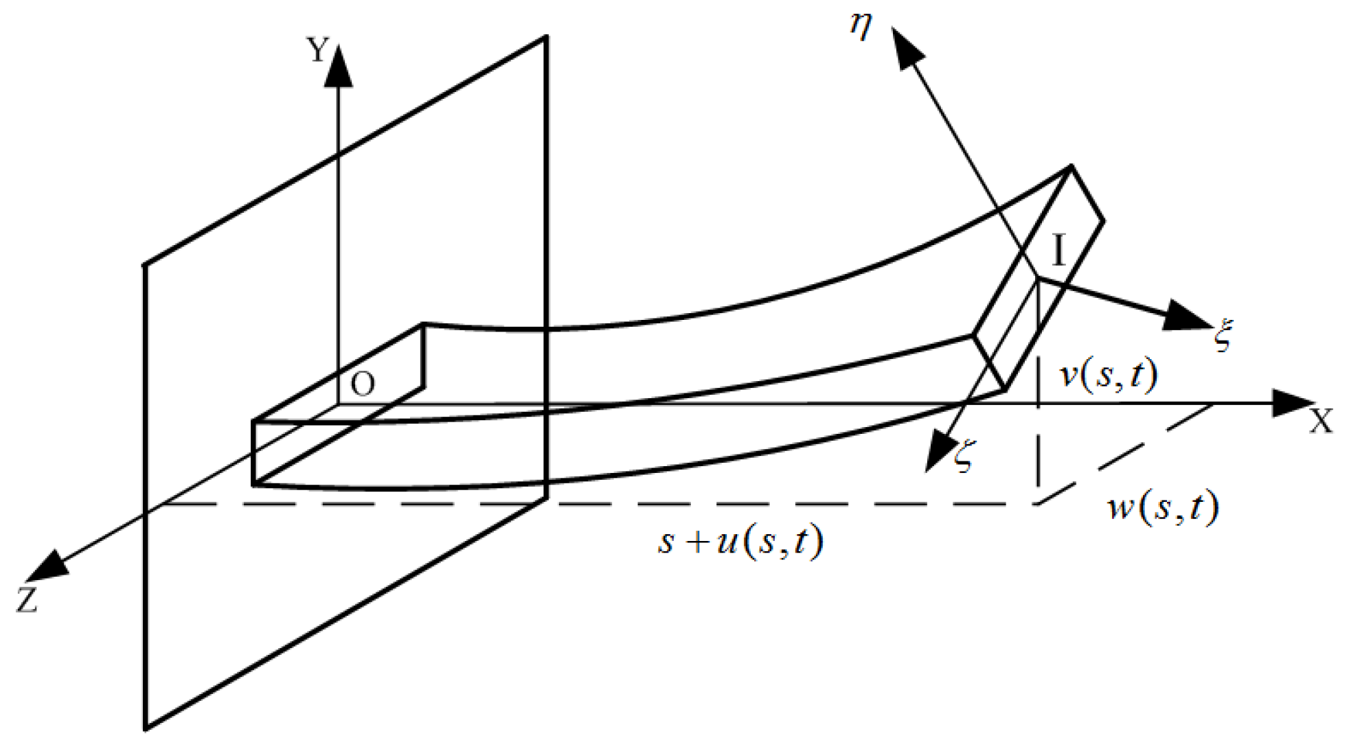
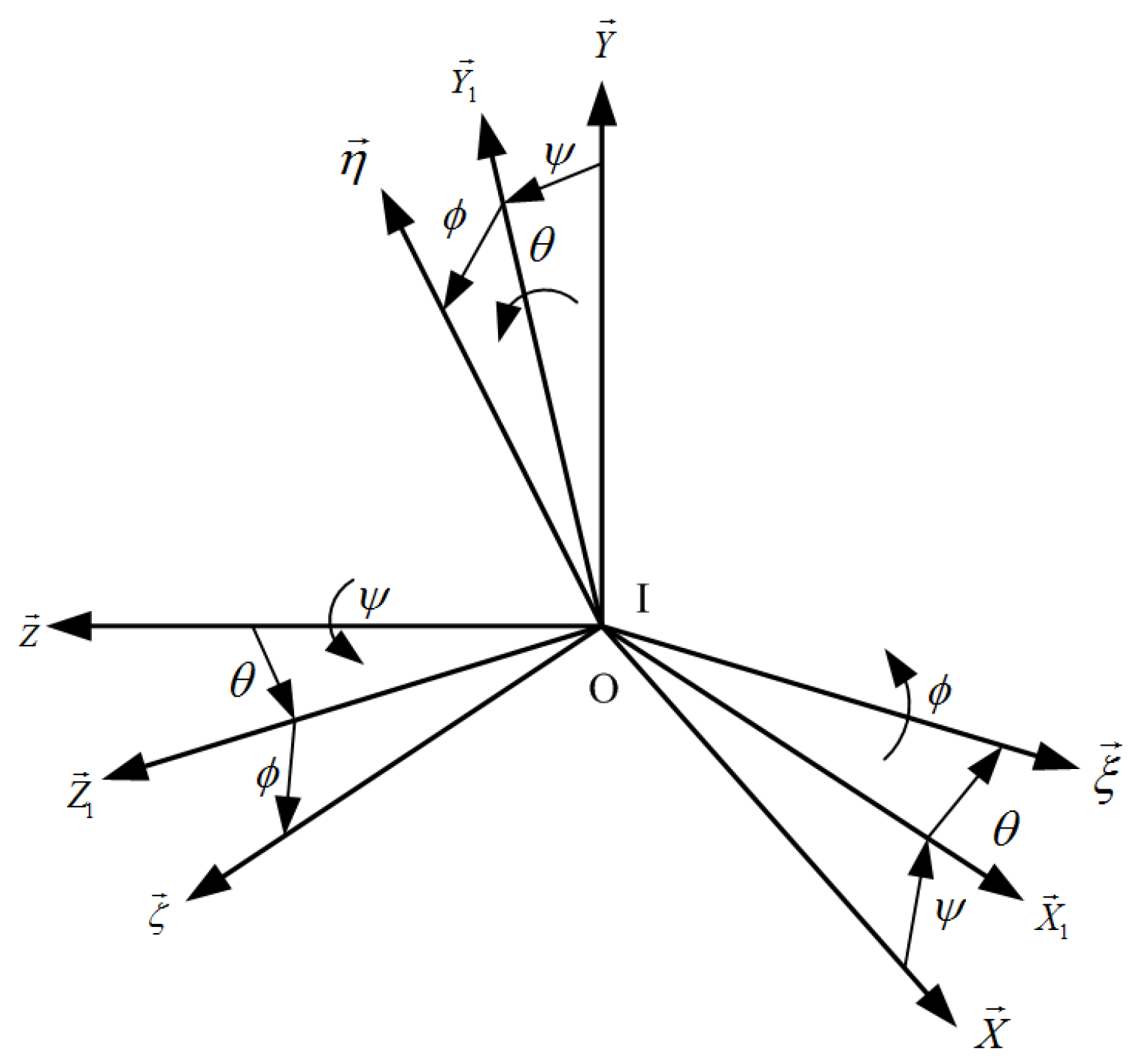
2. Modeling of the Harvester System

Figure 1a shows the energy harvester using piezoelectric cantilever beam (PZT) and its working environment. The energy harvester is composed of a piezoelectric cantilever beam and an eccentric cylinder tip. Figure 1b shows the schematic of energy harvester. Table 1 lists the geometric and physical properties of the energy harvesting system. The symbolic variables e and d are the eccentricity distance and diameter of cylinder eccentric hole, respectively, which determine the value of the eccentric distance of mass ld.
To model the harvester, the following assumptions are adopted:
(1)
The piezoelectric beam is assumed to be inextensible.
(2)
The attachments of the tip cylinder, beam and fixed end are assumed to be rigid.
(3)
The beam is an Euler–Bernoulli beam.
Figure 2 shows a schematic diagram of the cantilever beam. L and b are the length and width of the beam (Baoding Hengsheng Acoustics Electron Apparatus Co., Ltd®, Baoding, China), respectively. The thickness of the PZT layer made of PZT 5H defined in Table 1 is hp, and that of the substrate layer is hs. Two coordinate systems are used to describe the coupled bending–torsion motions of the beam. The reference coordinate system (O-XYZ) is fixed to the clamped side of the beam, which is adopted to describe the bending motion. s is used as the arc-coordinate in the length direction of the beam. In the fixed end, s = 0, and s = L in the tip. s + u(s, t), v(s, t) and w(s, t) are the displacements of the infinitesimal element at three directions in the coordinate system O-XYZ. Meanwhile, a local coordinate system (I-ξηζ) is adopted to describe the torsion motion. The axis I-ξ, I-η and I-ζ are the central principal axes of the cross section in three directions.
The local coordinate system I-ξηζ can be obtained by coordinating the rotation of the reference coordinate system, as shown in Figure 3. Firstly, O-X1, O-Y1 are obtained by a counter-clockwise rotation of O-X, O-Y with respect to the axis O-Z by the angle ψ. Secondly, I-ξ, O-Z1 are obtained by a rotation of O-X1, O-Z with respect to the axis O-Y1 by the angle θ. Finally, I-η, I-ζ are obtained by a rotation of O-Y1, O-Z1 with respect to the axis O-ξ by the angle φ. As a result, the angular velocity of the three rotation processes can be derived by the coordinate transformation, as shown in Equation (1).
ω ( s , t ) = ψ ˙ Z + θ ˙ Y 1 + ϕ ˙ ξ = ( ϕ ˙ ψ ˙ sin θ ) ξ + ( ψ ˙ cos θ sin ϕ + θ ˙ cos ϕ ) η + ( ψ ˙ cos θ cos ϕ θ ˙ sin ϕ ) ζ = ω ξ ξ + ω η η + ω ζ ζ
where the over dot denotes the derivative with respect to time t, and the vector arrow denotes the vector along the axes. ωξ, ωη, ωζ are the angular velocity of the rotating beam with respect to the axes I-ξ, I-η and I-ζ.
According to the practical work environment of the coupled bending–torsion motions of the beam, it is necessary to keep the mathematical model as simple as possible. Compared with other displacements, the longitudinal vibration displacement u(s, t), and rotation angular displacements ψ(s, t) and θ(s, t) are so small that they can be neglected. As a result, u(s, t) = 0, ψ(s, t) = θ(s, t) = 0, and from Equation (1), ωξ = ϕ ˙ , ωη = ωζ = 0.
Next, the Lagrange’s equations are used to derive the governing equations of the motion of the harvesting system.
t ( L μ ˙ ) ( L μ ) = δ W δ μ
The kinetic energy of the system is the sum of the kinetic energies of the beam (Tb), the eccentric cylinder (Tc) and the additional kinetic energy of fluid (Tf).
T b = 1 2 ρ b [ V b ( v ˙ 2 + w ˙ 2 ) d V b + 0 L ( I ξ ω ξ 2 ) d s ]
where ρb and Vb are the density and volume of the beam, which concludes two parts: the PZT and substrate layer. Iξ is the rotary inertia per unit length with respect to the axis I-ξ, given by:
I ξ = ( b 2 + h 2 ) 12
where h is the thickness of the beam.
T c = 1 2 M c [ ( v ˙ + v ˙ L c 2 ) 2 + ( w ˙ + w ˙ L c 2 ) 2 ] | s = L + 1 2 J c ξ ω ξ 2 | s = L
where D and d are the diameter of the cylinder and the eccentric hole, respectively. Mc and J are the mass and the rotary inertia with respect to the axis I-ξ of the eccentric cylinder, as follows:
J c ξ = 1 2 M c ( D 2 4 + d 2 4 ) 1 2 π ρ c d 2 4 L c e 2 T f = 1 2 M f [ ( v ˙ + v ˙ 2 L c L f 2 | s = L ) 2 + ( w ˙ + w ˙ 2 L c L f 2 | s = L ) 2 ] + 1 2 J f ξ ω ξ 2 | s = L
where Mf and J are the fluid-added mass and rotary inertia with respect to the axis I-ξ of the fluid due to the vibration of the eccentric cylinder, given by:
M f = C M ρ f π D 2 L f 4
where CM = 1 is the fluid-added mass coefficient.
J f ξ = M f D 2 8
The potential energies of the whole system include the potential energy (Ui), the electric potential energy (UV) of the beam and the gravitational potential energy (Ug) of the system.
U i = 1 2 V s ( σ s ε s + τ s γ s ) d V s + 1 2 V p [ σ p ε p + τ p γ p ] d V p
where the strains and stresses in the substrate and PZT layers are:
ε 11 = z ϕ η y η γ 12 = 2 ε 12 = z ϕ γ 13 = 2 ε 13 = y ϕ σ 11 s = E s ε 11 σ 12 s = 2 G s ε 12 σ 13 s = 2 G s ε 13 σ 12 p = 2 G p ε 12 σ 13 p = 2 G p ε 13
Due to the poling of the PZT layer, the strain and electric displacement vector are governed by the constitutive equations, given by:
σ 11 p = E p ε 11 e 31 E 2 D 2 = e 31 ε η + 11 E 2
where Es and Ep are the Young’s modulus at constant electric field, Gs and Gp are the shear modulus, E2 is the electric field intensity in the poling direction, and V(t) is the voltage between the two piezoelectric electrodes.
E 2 ( t ) = V ( t ) / h p U V = 1 2 V p E 2 D 2 d V p
where Vp is the volume of the PZT layer.
U g = M c g x ( s , t ) s | s = L [ x ( s , t ) + L c 2 x ( s , t ) s | s = L ] + V b ρ b g x ( s , t ) x ( s , t ) s d V b
where x(s, t) is the displacement of the beam in three axes direction of the reference coordinate system.
The virtual work includes the virtual work of the external resistance δWR, lift force δWF, buoyancy of fluid δWb, mechanical damping δWc and fluid-added damping δWcf.
δ W R = V ( t ) δ Q ( t )
where Q(t) is the charge between the piezoelectric electrodes.
δ W F = F ( t ) δ [ v ( s , t ) | s = L s + v ( s , t ) | s = L s ( L c L f 2 ) ] + F ( t ) l d δ ϕ
where ld is the eccentric distance of mass and given by:
l d = d 2 D 2 d 2 e
and F(t) is the lift force. It is generated when the eccentric cylinder is subjected to the incoming fluid [22], as:
F ( t ) = C L ( t ) ρ f D U 0 2 L f 2
where U0 is the speed of the incoming fluid. CL is the vortex lift coefficient. The fluid variable q is interpreted as a reduced vortex lift coefficient, which is governed by Van der Pol equation [31], and ωf is the vortex shedding frequency.
q ¨ + ε ω f ( q 2 1 ) q ˙ + ω f 2 q = f
where
q ( t ) = 2 C L ( t ) / C L 0
ω f = 2 π S t U 0 D
where CL0 = 0.3 [32]. And f is the nondimensional force of vortex [22], given by:
f = ( A D ) d 2 x ¯ d t 2 = ( A D ) [ 2 x ( s , t ) t 2 | s = L s + ( L c L f 2 ) 3 x ( s , t ) s t 2 | s = L s + 2 ϕ ( s , t ) t 2 | s = L s ]
The virtual work of the buoyancy of fluid δWb is:
δ W b = V w ρ f g x ( s , t ) s | s = L s δ [ x ( s , t ) + ( L c L f 2 ) x ( s , t ) s | s = L s ] d V f
The virtual work of fluid-added damping δWcf is:
δ W c f = c f v ( s , t ) t | s = L s ( L c L f 2 ) δ [ v ( s , t ) | s = L s ] + c f w ( s , t ) t | s = L s ( L c L f 2 ) δ [ w ( s , t ) | s = L s ] + c f ω ξ D 2 δ ϕ ( s , t ) | s = L S
where
c f = γ ω f ρ f D 2
where γ = 0.8 [22] is the fluid-added damping coefficient.
δ W c = 0 L c m [ v ˙ δ v ( s , t ) + w ˙ δ w ( s , t ) ] d s
where cm is the mechanical damping coefficient measured by experiment.
In order to solve the above equations, the bending vibration displacements v(s, t), w(s, t) and torsion angular displacement φ(s, t) are expressed by using Galerkin procedure [4] in the form of
v ( s , t ) = i = 1 n φ v i ( s ) r i ( t )
w ( s , t ) = i = 1 n φ w i ( s ) r i ( t )
ϕ ( s , t ) = i = 1 n φ ϕ i ( s ) r i ( t )
where φ(s) and r(t) are the mode shapes and the model coordinates, respectively. They can be expressed as:
φ v i ( s ) = A 1 sin λ 1 i s + B 1 cos λ 1 i s + C 1 sinh λ 1 i s + D 1 cosh λ 1 i s φ w i ( s ) = A 2 sin λ 2 i s + B 2 cos λ 2 i s + C 2 sinh λ 2 i s + D 2 cosh λ 2 i s φ ϕ i ( s ) = A 3 sin λ 3 i s + B 3 cos λ 3 i s
where the An, Bn, Cn and Dn are arbitrary constants and λni are determined by the natural frequency of the piezoelectric beam system, given by:
λ 1 i = ρ E I η S ρ E I ζ S 4 λ 2 i λ 1 i 4 E I ζ ρ S = λ 3 i 2 G I p J c ξ
where EIη and EIζ are the bending stiffness of the beam with respect to axes I-η, I-ζ. GIp is the torsion stiffness of the beam with respect to axis I-ξ, as follows:
E I η = b ( E s ( h b 3 h a 3 ) + E p ( h c 3 h b 3 ) ) 3 E I ζ = b 3 ( E s ( h b h a ) + E p ( h c h b ) ) 12
G I p = G s [ h s b 3 12 + b ( h b 3 h a 3 ) 3 ] + G p [ h p b 3 12 + b ( h c 3 h b 3 ) 3 ]
where ha, hb and hc are the positions of the layers given with respect to the neutral axis which are defined in Figure 4.
h 0 = ( h s + h p ) E p h p 2 ( E p h p + E s h s ) + h s 2
as follows:
h a = h 0 h b = h s h 0 h c = ( h s + h p ) h 0
According to the work condition, their associated boundary conditions are used to solve the mode shapes above.
v ( 0 , t ) = 0 v s | ( 0 , t ) = 0 w ( 0 , t ) = 0 w s | ( 0 , t ) = 0 ϕ ( 0 , t ) = 0
E I η 2 v s 2 | s = L s + L c 2 M c ( 2 v t 2 + 3 v s t 2 L c 2 ) | s = L s + ( L c L f 2 ) M f [ 2 v t 2 + 3 v s t 2 ( L c L f 2 ) ] | s = L s + M c l d L c 2 2 ϕ t 2 | s = L s = 0
E I η 3 v s 3 | s = L s M c ( 2 v t 2 + 3 v s t 2 L c 2 ) | s = L s M f [ 2 v t 2 + 3 v s t 2 ( L c L f 2 ) ] | s = L s M c l d 2 ϕ t 2 | s = L s = 0
E I ζ 2 w s 2 | s = L s + L c 2 M c ( 2 w t 2 + 3 w s t 2 L c 2 ) | s = L s + ( L c L f 2 ) M f [ 2 w t 2 + 3 w s t 2 ( L c L f 2 ) ] | s = L s = 0
E I ζ 3 w s 3 | s = L s M c ( 2 w t 2 + 3 w s t 2 L c 2 ) | s = L s M f [ 2 w t 2 + 3 w s t 2 ( L c L f 2 ) ] | s = L s = 0
G I p ϕ s | s = L s + J c ξ 2 ϕ t 2 | s = L s + M c l d ( 2 v t 2 + 3 v s t 2 L c 2 ) | s = L s = 0
By substituting Equations (19)–(21) into Equations (24)–(29), the equations of boundary conditions expressed by mode shapes can be written as:
φ v i ( 0 ) = 0 φ v i ( 0 ) = 0 φ w i ( 0 ) = 0 φ w i ( 0 ) = 0 φ ϕ i ( 0 ) = 0
E I η φ v i ( L s ) L c 2 M c ω i 2 ( φ v i ( L s ) + φ v i ( L s ) L c 2 ) ( L c L f 2 ) M f ω i 2 [ φ v i ( L s ) + φ v i ( L s ) ( L c L f 2 ) ] M c ω i 2 l d L c 2 φ ϕ i ( L s ) = 0
E I η φ v i ( L s ) + M c ω i 2 ( φ v i ( L s ) + φ v i ( L s ) L c 2 ) + M f ω i 2 [ φ v i ( L s ) + φ v i ( L s ) ( L c L f 2 ) ] + M c ω i 2 l d φ ϕ i ( L s ) = 0
E I ζ φ w i ( L s ) L c 2 M c ω i 2 ( φ w i ( L s ) + φ w i ( L s ) L c 2 ) ( L c L f 2 ) M f ω i 2 [ φ w i ( L s ) + φ w i ( L s ) ( L c L f 2 ) ] = 0
E I ζ φ w i ( L s ) + M c ω i 2 ( φ w i ( L s ) + φ w i ( L s ) L c 2 ) + M f ω i 2 [ φ w i ( L s ) + φ w i ( L s ) ( L c L f 2 ) ] = 0
G I p φ ϕ i ( L s ) J c ξ ω i 2 φ ϕ i ( L s ) M c l d ω i 2 ( φ v i ( L s ) + φ v i ( L s ) L c 2 ) = 0
Normalizing the eigenfunctions using the following orthogonality conditions of mass and stiffness, the relations between different mode shapes are obtained.
ρ b V b ( φ v i ( s ) φ v j ( s ) + φ w i ( s ) φ w j ( s ) ) d V b + M c ( φ v i ( L s ) + L c 2 φ v i ( L s ) ) ( φ v j ( L s ) + L c 2 φ v j ( L s ) ) + M c ( φ w i ( L s ) + L c 2 φ w i ( L s ) ) ( φ w j ( L s ) + L c 2 φ w j ( L s ) ) + M f ( φ v i ( L s ) + ( 2 L c L f ) 2 φ v i ( L s ) ) ( φ v j ( L s ) + ( 2 L c L f ) 2 φ v j ( L s ) ) + M f ( φ w i ( L s ) + ( 2 L c L f ) 2 φ w i ( L s ) ) ( φ w j ( L s ) + ( 2 L c L f ) 2 φ w j ( L s ) ) + ( J c ξ + J f ξ ) [ φ ϕ i ( L s ) + φ w i ( L s ) φ v i ( L s ) ] [ φ ϕ j ( L s ) + φ w j ( L s ) φ v j ( L s ) ] = δ i j
0 L φ v i E I η φ v j d s + 0 L φ ϕ i G I p φ ϕ j d s = δ i j ω i 2
where δij is the Kronecker delta, defined as 1 when i is equal to j and 0 otherwise.
As a consequence, combining the boundary conditions (30)–(35) and orthogonality conditions (36) and (37), as well as Equation (23), mode shapes and natural frequency of the beam can be obtained. As the energy harvesting system is designed to work in the low frequency environment, the first mode shape [33] is accurate enough to research the energy harvesting in this paper.
By substituting Equations (19)–(21) and the orthogonality conditions (36) and (37) into the kinetic energy Equations (3)–(5), potential energy Equations (6), (9) and (10), and the virtual work Equations (11), (12), (16)–(18), the energy equations and virtual work equations are rewritten as:
The kinetic energy equation T:
T = r ˙ 2 ( t ) 2
The potential energy equation U:
U = H 1 V r ( t ) + 1 2 ω i 2 r 2 ( t ) 1 2 H 1 V r ( t ) + H 2 V 2 + H 3 r 2 ( t )
where Hn is the coefficient of the variables, given by:
H 1 = e 31 b ( h b 2 h a 2 ) 2 h p 0 L p φ v ( s ) d s
H 2 = ε 11 b L p 2 h p
H 3 = M c g [ φ v ( L s ) φ v ( L s ) + L c 2 φ v 2 ( L s ) + φ w ( L s ) φ w ( L s ) + L c 2 φ w 2 ( L s ) ] + ρ b S b g 0 L s ( φ v φ v + φ w φ w ) d s
The virtual work equation:
δ W δ r ( t ) = H 4 F ( t ) + H 5 r ( t ) + H 6 r ˙ ( t )
where the coefficient Hn are expressed as:
H 4 = [ φ v ( L s ) + φ v ( L s ) ( L c L f 2 ) ] + l d φ ϕ ( L s )
H 5 = ρ w g π D 2 4 0 L f [ φ v ( s ) φ v ( L s ) + ( L c L f 2 ) φ v 2 ( s ) ] d s + ρ w g π D 2 4 0 L f [ φ w ( L s ) φ w ( s ) + ( L c L f 2 ) φ w 2 ( s ) ] d s
H 6 = c f φ v 2 ( L s ) c f φ w 2 ( L s ) c f D 2 φ ϕ 2 ( L s ) 0 L c m [ φ v 2 ( s ) + φ w 2 ( s ) ] d s
Now, the Lagrange function which is the subtraction of kinetic energy Equation (38) and potential energy Equation (39) is established and expressed as:
L = T U = 1 2 r ˙ 2 ( t ) ( 1 2 ω i 2 + H 3 ) r 2 ( t ) 1 2 H 1 V r ( t ) H 2 V 2
This occurs when substituting Equation (40) and Lagrange function (41) into Lagrange’s Equation (2), and assigning variables r and V, respectively. Then, the following state equations are obtained:
r ¨ ( t ) + υ r ˙ ( t ) + λ r ( t ) + θ V = κ F ( t )
V ( t ) R + C p d V ( t ) d t θ r ˙ ( t ) = 0
where the coefficients of the state variables are expressed as:
υ = H 6 , λ = ω i 2 + 2 H 3 H 5 , κ = H 4 , C p = 2 H 2 , and   θ = H 1 2
Substituting the Equations (19)–(21) into Equation (15) the nondimensional force of vortex f is rewritten as:
f = H 7 r ¨ ( t )
where the coefficient H7 is given by:
H 7 = ( A D ) [ φ v ( L s ) + ( L c L f 2 ) φ v ( L s ) + φ w ( L s ) + ( L c L f 2 ) φ w ( L s ) + φ ϕ ( L s ) ]
According to Equations (42)–(44), a space state equation of the energy harvesting system is established, and expressed as:
X ˙ = [ X 2 κ C L 0 ρ w D U 2 L c 4 X 4 υ X 2 λ X 1 θ X 3 θ C p X 2 X 3 C p R X 5 q ¨ ]
where X is the space state variable, written as:
X = [ X 1 X 2 X 3 X 4 X 5 ] = [ r r ˙ V q q ˙ ]
Equation (45) can be numerically solved by using the solver of ode45 in MATLAB (MathWorks, Inc®, Natick, MA, USA).

3. Numerical Analysis and Experimental Validation

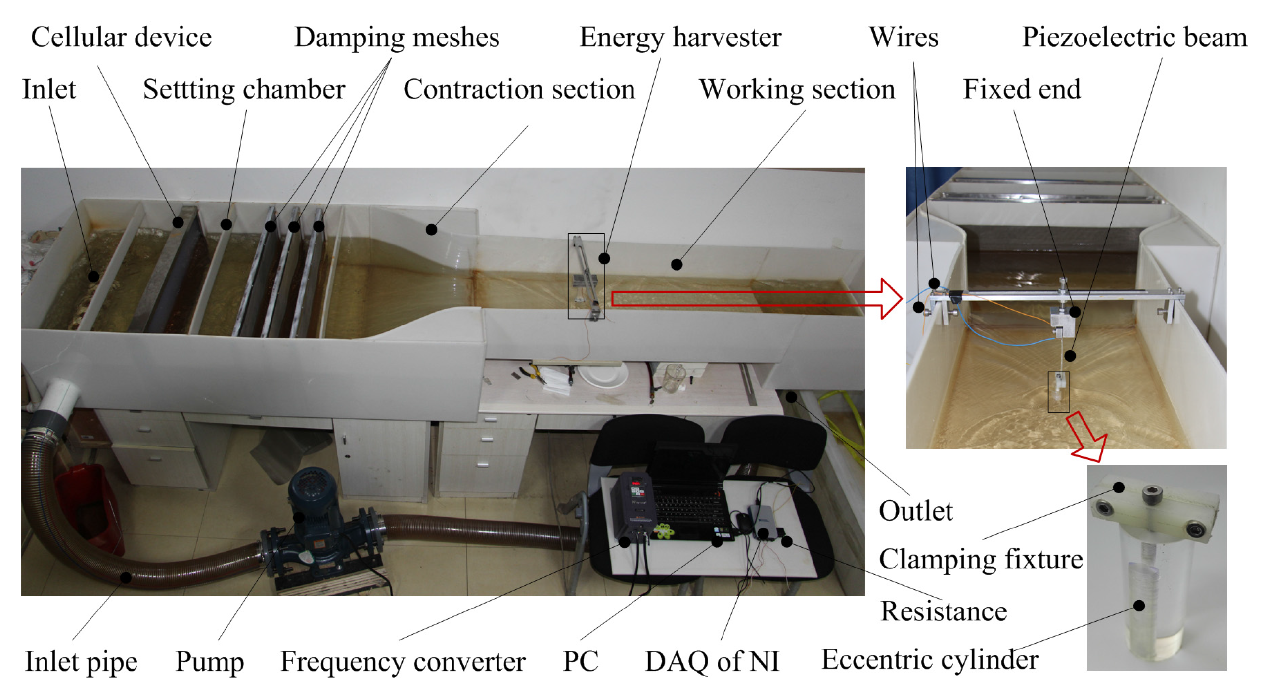
3.1. Experimental Setup

Harvesters are fabricated with piezoelectric cantilever beams and tip eccentric cylinders. The beam has an aluminum layer and a PZT layer, which are bonded together by epoxy. The tip cylinder is made of acrylic with an eccentric hole. They are joined by a symmetry rectangular clamping fixture made of polyamide.
The experiment was carried out in a test rig system, as shown in Figure 5. This test system is composed of a water channel, pump (Shimge Co., Ltd®; Hangzhou, China), frequency converter (Shenzhen Junhui Electronics Co., Ltd®, Shenzhen, China), data acquisition and processing system. The water channel is mainly composed of three sections: the setting chamber, (equipped with) a cellular device (Qingdao Tonglide plastic buzzer hives Co., Ltd®, Qingdao, China), and damping meshes (Hangzhou Kuangshi Co., Ltd®, Hangzhou, China), aiming to steady the flow. The contraction section returns the flow speed of water from the setting chamber. The experiments were performed in the working section. The pump makes the water cycle in the channel. The frequency converter is used to vary the work frequency of the pump, regulating the discharge of water, and then varying the flow speed of water. The data acquisition and processing systems include a DAQ of NI (National Instruments, Austin, TX, USA), and a PC (Lenovo Group Ltd®, Beijing, China), which can measure and process the output voltage across the external resistance R in real time.

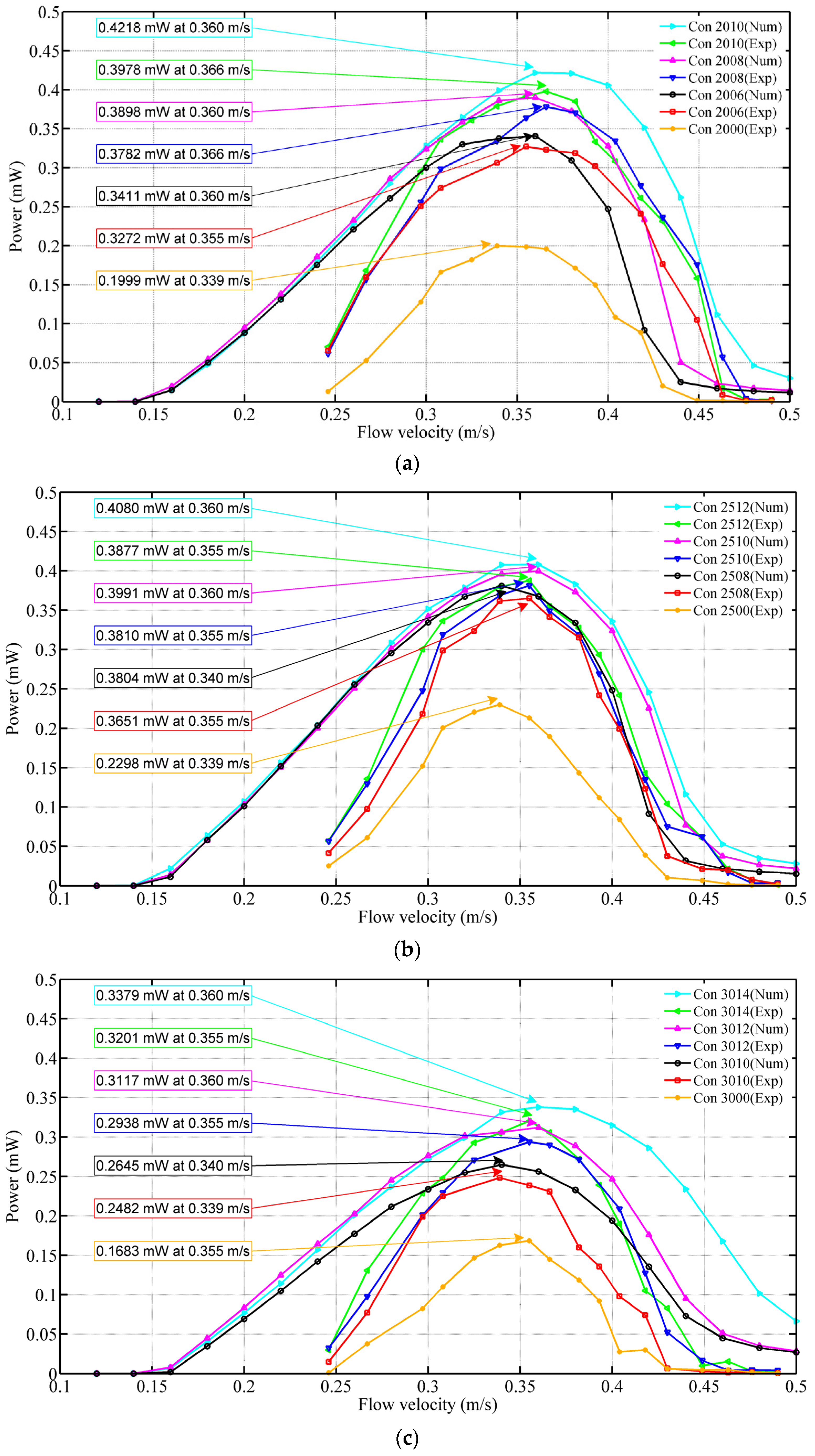
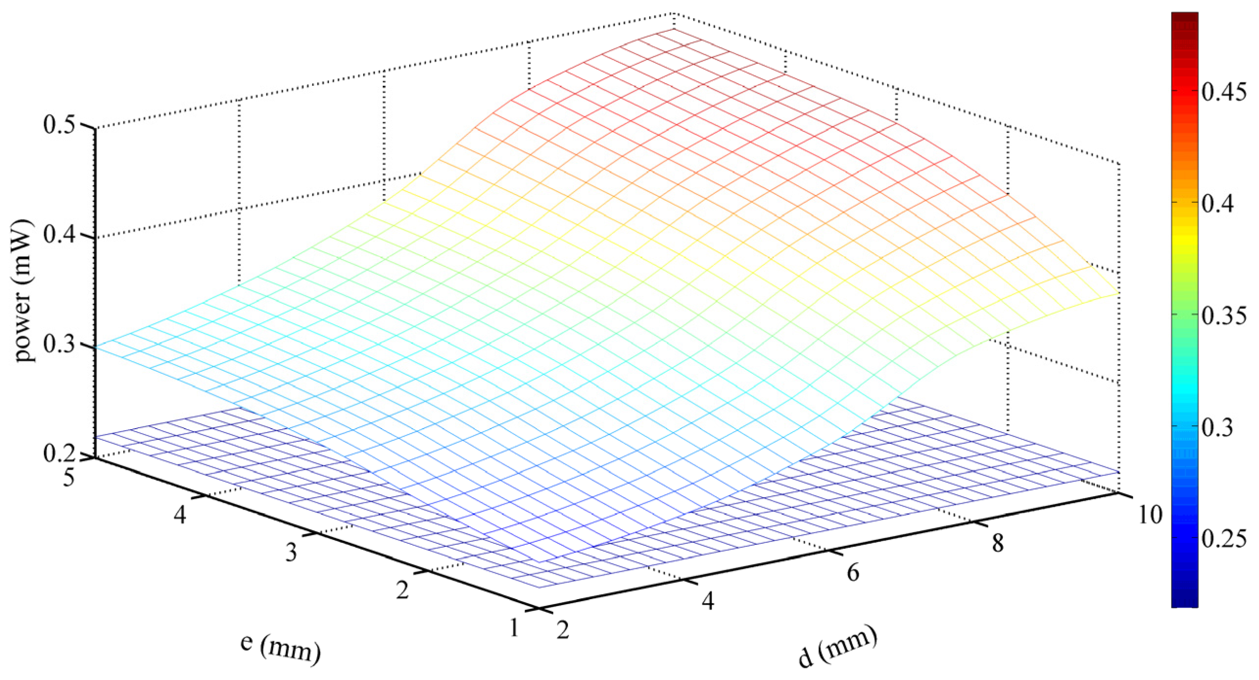
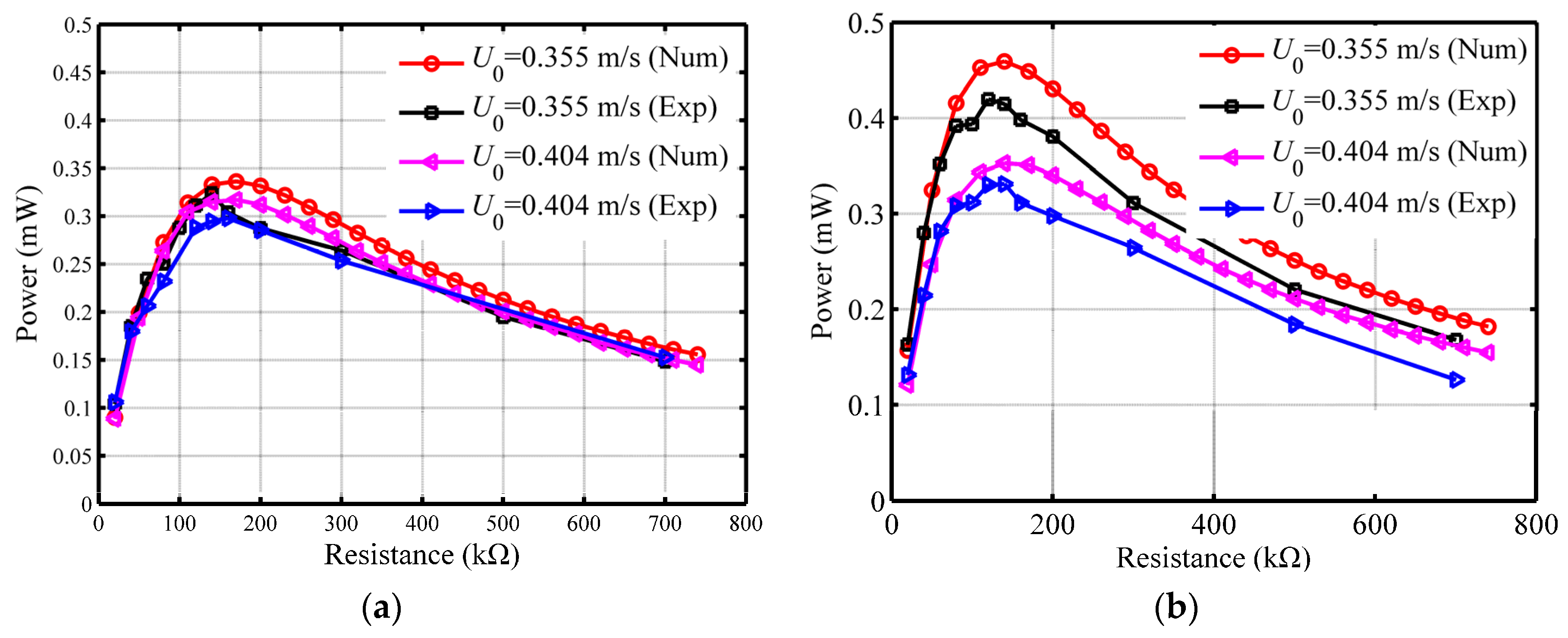
3.2. Numerical and Experimental Analysis

Figure 6 illustrates the numerical and experimental values of average power versus external load resistance R. The configurations of the harvester are D = 20, d = 10 and e = 5 mm. The powers are measured at flow velocities of 0.355 and 0.404 m/s, respectively. It is found that the power increases at first then decreases with the increase of the resistance value. There is an optimal resistance around 170 and 140 kΩ for the output power when the widths of the beams are 20 and 25 mm, respectively. From Figure 6, one can find that the optimal resistance is not related to the flow velocities, and the optimal resistance of the numerical analysis is consistent with that of the experiment.
Table 2 shows the configurations of eccentric cylinder used in experiment. To document the measured results, it is necessary to number the cylinders. The sequence numbers represent the diameter of the cylinder (D) and the diameter of the eccentric hole (d). For example, the number Con 2006 represents a cylinder with D = 20 and d = 6 mm. In addition, the number Con 2000 represents a solid cylinder with a diameter of 20 mm.
Figure 7 illustrates the average power of harvesters with the configurations in Table 2, which are numerically calculated and experimentally measured at various flow velocity U0 with the same resistance of 80 kΩ. It can be found that the output power P first increases to Pmax (maximum value of power) with U0, while U0 continues to increase, P decreases. The optimal velocity is about 0.339–0.366 m/s for the nine configurations. As the flow velocity U0 rises up, the vortex shedding frequency ωf increases, which is gradually close to the natural frequency of the harvester. As a result, the lift force from the vortex drives the eccentric cylinder to resonance, and leads to a significant increase in amplitude of the cylinder rigidly connected with piezoelectric beam. At the same time, the optimal velocity becomes greater with the increase of d, which causes a lighter mass of the cylinder. As a consequence, the natural frequency of the harvester increases.
Meanwhile, there should be a positive correlation between Pmax and ld dominated by the eccentricity distance e and the diameter of cylinder eccentric hole d. It can be concluded that Pmax increases with the increase of eccentricity of mass ld, as shown in Figure 7a and Table 3. Pmax is 0.3978 mW with a maximum value of ld in configurations 2006, 2008, and 2010 in Figure 7a. Besides, the Pmax of the solid cylinder is 0.1999 mW, and there is an improvement of 99%. The torque excited by vortex becomes bigger when ld increases. It leads to a bigger twist angle. Further, more energy is harvested.
In Figure 7, it also can be summarized that the cylinder diameter D has a negative influence on Pmax. Pmax decreases from 0.3978 to 0.2482 mW, while D increases from 20 to 30 mm with a similar ld in Con 2010, Con 2510, and Con 3010. In addition, the same conclusion can be obtained from Table 3. The lift force reduces with the increase of diameter D, which weakens cylinder vibration response.
By comparing the results of different experiments, the best configuration and working environment for the harvester is summarized. The optimal load resistance is 170 kΩ when b = 20 mm, and 140 kΩ when b = 25 mm. The greater the ld is, the greater Pmax will be. Therefore, ld should be designed as large as possible if the structure processing permits. Similarly, a harvester with a smaller cylinder diameter D has a greater Pmax, and D is the minimum value of 20 mm in this paper.
The best configurations and working environments for the harvester are concluded by experiments. The validity of the model derived is verified. As a result, the model can be used to numerically analysis the harvesting characteristics of harvesters in varieties of situations and configurations. Figure 8 shows the numerical analysis results of the harvester with D = 20 mm and b = 20 mm at the optimal load resistance. Compared with the harvester undergoing bending only with an output power of 0.2188 mW shown in the bottom of Figure 8, the output power of the harvester with configurations d = 10 and e = 5 mm undergoing bending–torsion is 0.4854 mW. This result implies that the present work is meaningful for the design of harvesters.

4. Conclusions

In this paper, a vortex-induced vibration piezoelectric energy harvester undergoing bending–torsion vibrations by the tip eccentric cylinder was designed and fabricated. The water-to-electricity conversion characteristics in low-speed water flow was studied. A distributed parameter beam model was established based on Euler–Bernoulli beam theory. The mode shapes and model coordinates were used as basic functions to represent the displacements of harvester system in a Galerkin procedure. Energy-governing coupled equations of the harvesting system were derived by using the Lagrange’s equations. Numerical models were used to analyze and predict the best configurations and optimal work environments for the harvesters by calculating the output voltage. Experiments have been designed and conducted. The correctness of the numerical models was verified. A harvester with D = 20 mm, d = 10 mm, e = 3 mm has a maximum power of 0.3978 mW. The eccentric hole setting of the harvester increases its harvesting power as much as 99%. This paper provides a practical significance in an efficient harvester’s design and manufacture.

Supplementary Materials

The following are available online at https://www.mdpi.com/2076-3417/7/2/116/s1. (1) Photos of experimental test platform; (2) Videos of experiments and tests.

Acknowledgments

This work was financially supported by the National Natural Science Foundation of China (Grant No. 51677043) and the Fundamental Research Funds for the Central Universities (Grant No. HIT. KISTP. 201412).

Author Contributions

All authors conceived and designed the experiments; Xiaobiao Shan and Rujun Song set up the experimental platform; Xiaobiao Shan and Jie Deng conducted the experiments; all authors contributed to analyzing the experimental data and writing the paper.

Conflicts of Interest

The authors declare no conflict of interest.

References

  1. Williams, C.B.; Yates, R.B. Analysis of a micro-electric generator for microsystems. Sens. Actuators A Phys. 1996, 52, 8–11. [Google Scholar] [CrossRef]
  2. Mitcheson, P.D.; Miao, P.; Stark, B.H.; Yeatman, E.M.; Holmes, A.S.; Green, T.C. Mems electrostatic micropower generator for low frequency operation. Sens. Actuators A Phys. 2004, 115, 523–529. [Google Scholar] [CrossRef] [Green Version]
  3. Erturk, A.; Inman, D.J. Issues in mathematical modeling of piezoelectric energy harvesters. Smart Mater. Struct. 2008, 17, 8479–8491. [Google Scholar] [CrossRef]
  4. Erturk, A.; Inman, D.J. A distributed parameter electromechanical model for cantilevered piezoelectric energy harvesters. J. Vib. Acoust. 2008, 130, 1257–1261. [Google Scholar] [CrossRef]
  5. Abdelkefi, A.; Najar, F.; Nayfeh, A.H.; Ayed, S.B. An energy harvester using piezoelectric cantilever beams undergoing coupled bending–torsion vibrations. Smart Mater. Struct. 2011, 20, 115007–115017. [Google Scholar] [CrossRef]
  6. Khameneifar, F.; Arzanpour, S.; Moallem, M. A piezoelectric energy harvester for rotary motion applications: Design and experiments. IEEE/ASME Trans. Mechatron. 2013, 18, 1527–1534. [Google Scholar] [CrossRef]
  7. Yang, Y.; Tang, L.; Li, H. Vibration energy harvesting using macro-fiber composites. Smart Mater. Struct. 2009, 18, 115025. [Google Scholar] [CrossRef]
  8. Kuna, M. Fracture mechanics of piezoelectric materials—Where are we right now? Eng. Fract. Mech. 2010, 77, 309–326. [Google Scholar] [CrossRef]
  9. Robbins, W.P.; Marusic, I.; Morris, D.; Novak, T.O. Wind-generated electrical energy using flexible piezoelectric mateials. In Proceedings of the ASME 2006 International Mechanical Engineering Congress and Exposition, Chicago, IL, USA, 5–10 November 2006; pp. 581–590.
  10. Akaydin, D.; Elvin, N.; Andreopoulos, Y. The performance of a self-excited fluidic energy harvester. Smart Mater. Struct. 2012, 21, 25007–25019. [Google Scholar] [CrossRef]
  11. Abdelkefi, A.; Hajj, M.R.; Nayfeh, A.H. Phenomena and modeling of piezoelectric energy harvesting from freely oscillating cylinders. Nonlinear Dyn. 2012, 70, 1377–1388. [Google Scholar] [CrossRef]
  12. Abdelkefi, A.; Yan, Z.; Hajj, M.R.; Yan, Z. Performance analysis of galloping-based piezoaeroelastic energy harvesters with different cross-section geometries. J. Intell. Mater. Syst. Struct. 2013, 25, 246–256. [Google Scholar] [CrossRef]
  13. Dai, H.L.; Abdelkefi, A.; Yang, Y.; Wang, L. Orientation of bluff body for designing efficient energy harvesters from vortex-induced vibrations. Appl. Phys. Lett. 2016, 108, 175–195. [Google Scholar] [CrossRef]
  14. Mehmood, A.; Abdelkefi, A.; Hajj, M.R.; Nayfeh, A.H.; Akhtar, I.; Nuhait, A.O. Piezoelectric energy harvesting from vortex-induced vibrations of circular cylinder. J. Sound Vib. 2013, 332, 4656–4667. [Google Scholar] [CrossRef]
  15. Dai, H.; Abdelkefi, A.; Wang, L. Theoretical modeling and nonlinear analysis of piezoelectric energy harvesting from vortex-induced vibrations. J. Intell. Mater. Syst. Struct. 2014, 25, 1861–1874. [Google Scholar] [CrossRef]
  16. Dai, H.L.; Abdelkefi, A.; Wang, L. Piezoelectric energy harvesting from concurrent vortex-induced vibrations and base excitations. Nonlinear Dyn. 2014, 77, 967–981. [Google Scholar] [CrossRef]
  17. Mackowski, A.W.; Williamson, C.H.K. An experimental investigation of vortex-induced vibration with nonlinear restoring forces. Phys. Fluids 2013, 25, 087101. [Google Scholar] [CrossRef]
  18. Dai, H.L.; Abdelkefi, A.; Wang, L. Vortex-induced vibrations mitigation through a nonlinear energy sink. Commun. Nonlinear Sci. Numer. Simul. 2016, 42, 22–36. [Google Scholar] [CrossRef]
  19. Dai, H.L.; Abdelkefi, A.; Wang, L. Modeling and nonlinear dynamics of fluid-conveying risers under hybrid excitations. Int. J. Eng. Sci. 2014, 81, 1–14. [Google Scholar] [CrossRef]
  20. Dai, H.L.; Abdelkefi, A.; Wang, L.; Liu, W.B. Time-delay feedback controller for amplitude reduction in vortex-induced vibrations. Nonlinear Dyn. 2015, 80, 59–70. [Google Scholar] [CrossRef]
  21. Violette, R.; De Langre, E.; Szydlowski, J. Computation of vortex-induced vibrations of long structures using a wake oscillator model: Comparison with dns and experiments. Comput. Struct. 2007, 85, 1134–1141. [Google Scholar] [CrossRef]
  22. Facchinetti, M.L.; de Langre, E.; Biolley, F. Coupling of structure and wake oscillators in vortex-induced vibrations. J. Fluids Struct. 2004, 19, 123–140. [Google Scholar] [CrossRef]
  23. Govardan, R. Modes of vortex formation and frequency response of a freely vibrating cylinder. J. Fluid Mech. 2000, 420, 85–130. [Google Scholar] [CrossRef]
  24. Goushcha, O.; Elvin, N.; Andreopoulos, Y. Interactions of vortices with a flexible beam with applications in fluidic energy harvesting. Appl. Phys. Lett. 2014, 104, 021919. [Google Scholar] [CrossRef]
  25. Abdelkefi, A. Aeroelastic energy harvesting: A review. Int. J. Eng. Sci. 2015, 100, 112–135. [Google Scholar] [CrossRef]
  26. Taylor, G.W.; Burns, J.R.; Kammann, S.A.; Powers, W.B.; Welsh, T.R. The energy harvesting eel: A small subsurface ocean/river power generator. IEEE J. Ocean. Eng. 2001, 26, 539–547. [Google Scholar] [CrossRef]
  27. Allen, J.J.; Smits, A.J. Energy harvesting eel. J. Fluids Struct. 2001, 15, 629–640. [Google Scholar] [CrossRef]
  28. Song, R.; Shan, X.; Lv, F.; Xie, T. A study of vortex-induced energy harvesting from water using pzt piezoelectric cantilever with cylindrical extension. Ceram. Int. 2015, 41, S768–S773. [Google Scholar] [CrossRef]
  29. Song, R.; Shan, X.; Lv, F.; Li, J.; Xie, T. A novel piezoelectric energy harvester using the macro fiber composite cantilever with a bicylinder in water. Appl. Sci. 2015, 5, 1942–1954. [Google Scholar] [CrossRef]
  30. Shan, X.; Song, R.; Fan, M.; Xie, T. Energy-harvesting performances of two tandem piezoelectric energy harvesters with cylinders in water. Appl. Sci. 2016, 6, 230. [Google Scholar] [CrossRef]
  31. Nayfeh, A.H. Introduction to Perturbation Techniques; Wiley-Interscience (John Wiley & Sons): New York, NY, USA, 2011; pp. 355–356. [Google Scholar]
  32. Blevins, R.D.; Saunders, H. Flow-Induced Vibration; Van Nostrand Reinhold Co.: New York, NY, USA; p. 6.
  33. Ayed, S.B.; Abdelkefi, A.; Najar, F.; Hajj, M.R. Design and performance of variable shaped piezoelectric energy harvesters. J. Intell. Mater. Syst. Struct. 2013, 25, 174–186. [Google Scholar] [CrossRef]
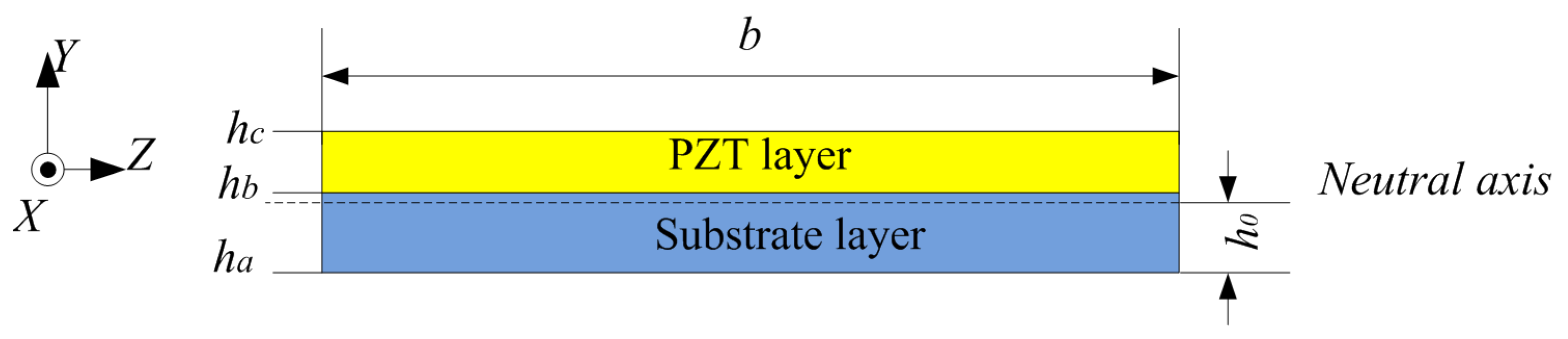
Figure 1. Energy harvester: (a) Harvester and its working environment; (b) Schematic of harvester.
Applsci 07 00116 g001
Figure 2. The cantilever beam.
Applsci 07 00116 g002
Figure 3. The coordinate transformation figure.
Applsci 07 00116 g003
Figure 4. The neutral axis.
Applsci 07 00116 g004
Figure 5. Experimental test platform.
Applsci 07 00116 g005
Figure 6. Numerical and experimental values of average power versus load resistance: (a) b = 20 mm; (b) b = 25 mm.
Applsci 07 00116 g006
Figure 7. Values of average power numerically calculated and experimentally measured at various flow velocities with different cylinder configurations of energy harvesters with a beam width of 25 mm (a) D = 20 mm; (b) D = 25 mm; (c) D = 30 mm.
Applsci 07 00116 g007
Figure 8. Maximum output power versus eccentricity distance e and cylinder eccentric hole diameter d.
Applsci 07 00116 g008
Table 1. The geometric and physical properties of energy harvesting systems.
ρpDensity of the piezoelectric layer (kg/m3)7800
ρsDensity of the substrate layer (aluminum; kg/m3)2700
ρfFluid density (kg/m3)1000
ρcDensity of the cylinder (acrylic; kg/m3)1200
EpYoung modulus of the piezoelectric layer (Gpa)59.77
EsYoung modulus of the substrate layer (Gpa)70
LLength of the beam (mm)85
bWidth of the beam (mm)25
hpThickness of the piezoelectric layer (mm)0.2
hsThickness of the substrate layer (mm)0.2
e31Piezoelectric constant (C/m2)−16.6
ε11Piezoelectric permittivity (nF/m)41.78
LcDiameter of the cylinder (mm)75
LfLength of the cylinder submerged in fluid (mm)60
Table 2. Configurations of the eccentric cylinder.
Configurations200620082010250825102512301030123014
D (mm)202020252525303030
d (mm)681081012101214
e (mm)5436.25547.565
ld (mm)0.4950.7620.9520.7130.9251.1980.9381.1421.392
Table 3. Pmax of different configurations of the eccentric cylinder when b = 20 mm.
Configurations 200020062008201025002508
Pmax (mW)0.18310.26630.2810.32670.21390.2763
Configurations251025123000301030123014
Pmax (mW)0.32540.32730.17640.2490.26240.2866

