
Seismic Failure Mechanism of Reinforced Cold-Formed Steel Shear Wall System Based on Structural Vulnerability Analysis

Abstract
:1. Introduction
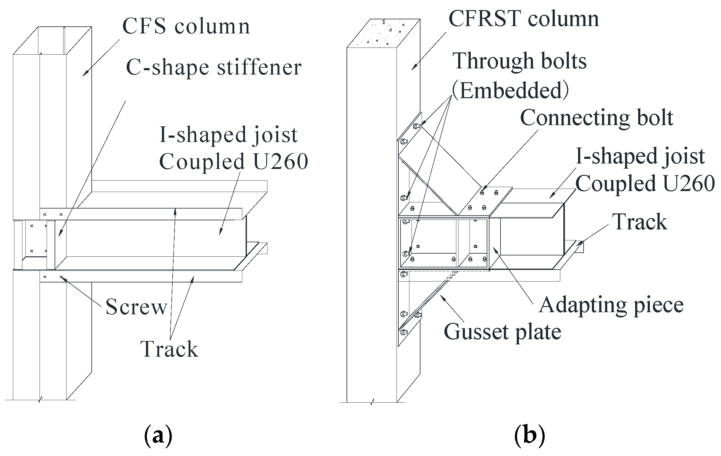
2. RCFS Shear Wall System
3. Structural Vulnerability Theory
3.1. Well-Formedness
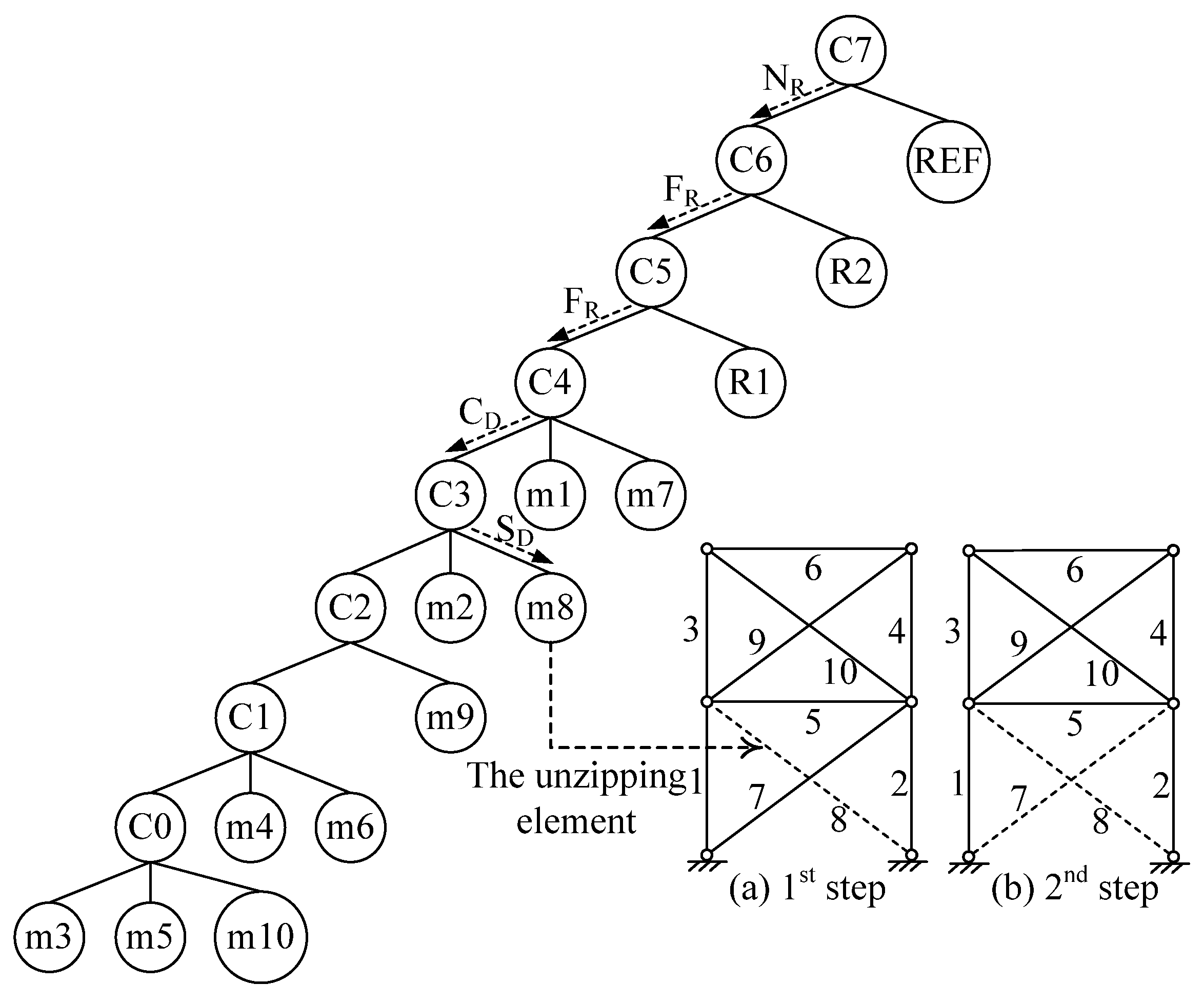
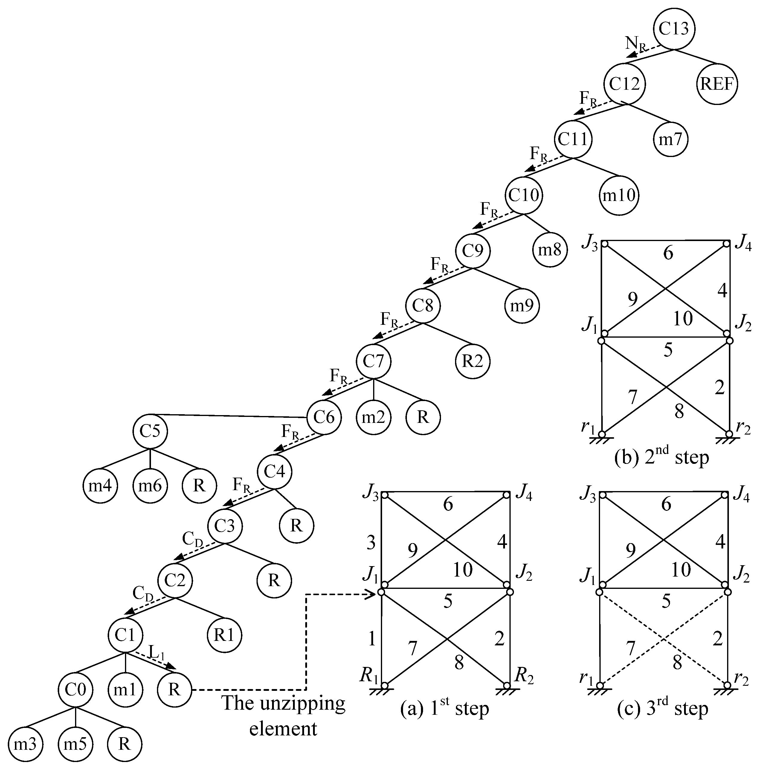
3.2. Clustering Process
3.3. Unzipping Process
- The subcluster is not a reference cluster, NR;
- The subcluster forms a ring with the reference cluster, FR;
- The subcluster connects directly to the reference cluster, but does not form a ring with the reference cluster, CD;
- The subcluster is a leaf cluster rather than a branch cluster, L;
- The subcluster has the least well-formedness, SQ;
- The subcluster has the smallest minimum damage demand, SD;
- The subcluster was clustered most recently, CL;
- If none of the above criteria apply, then a free choice is made, FC.
3.4. Vulnerability Index
- (1)
- Separateness (γ): it is measured by the ratio of the loss of well-formedness to the original well-formedness of the structure, which evaluates the damage consequence.where Q(S) and Q(S′) are the well-formedness of the original structure and residual structure, respectively. If no damage has occurred on the structure, the separateness is 0; however, if the structure is totally damaged, the value of γ equals 1.
- (2)
- Relative damage demand (Dr): it is calculated by the ratio of the damage demand for the corresponding failure mode to the total damage demand of the structure.where D is the total damage demand for the members in the structure corresponding to a particular failure mode; Dmax is the total damage demand of all the members in the structure.
- (3)
- Vulnerability index: it is an index to value the structural vulnerability, which is calculated by the ratio of the separateness to the relative damage demand.
4. Structural Vulnerability Analyses on Two-Story CFS Shear Wall Systems
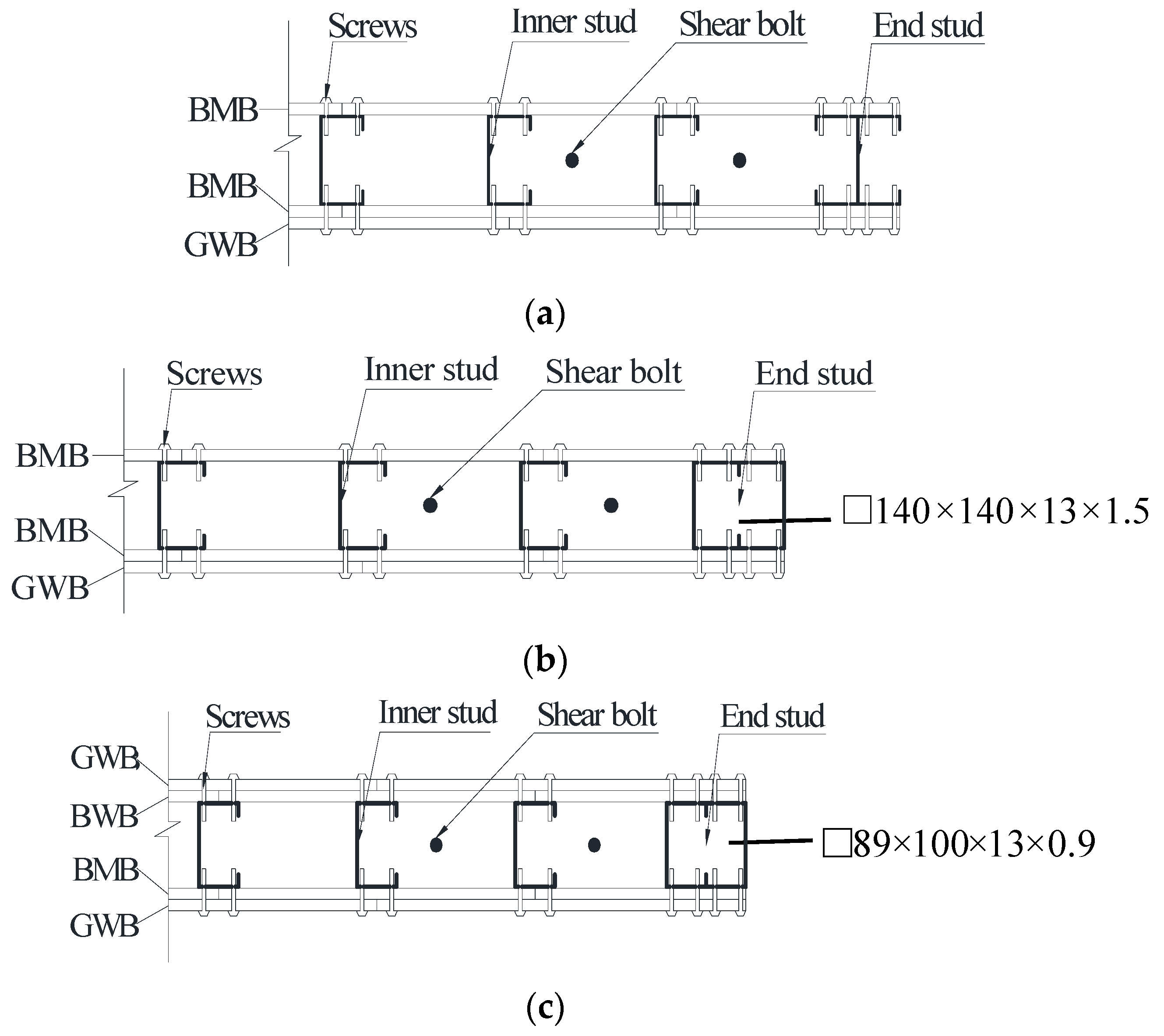
4.1. Traditional Shear Wall System W1
4.2. RCFS Shear Wall System W2
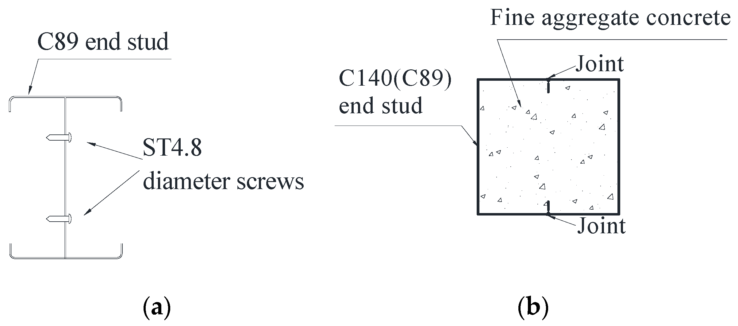
4.3. Effects of End Stud Type on the Collapse Modes of RCFS Shear Wall Systems
5. Conclusions
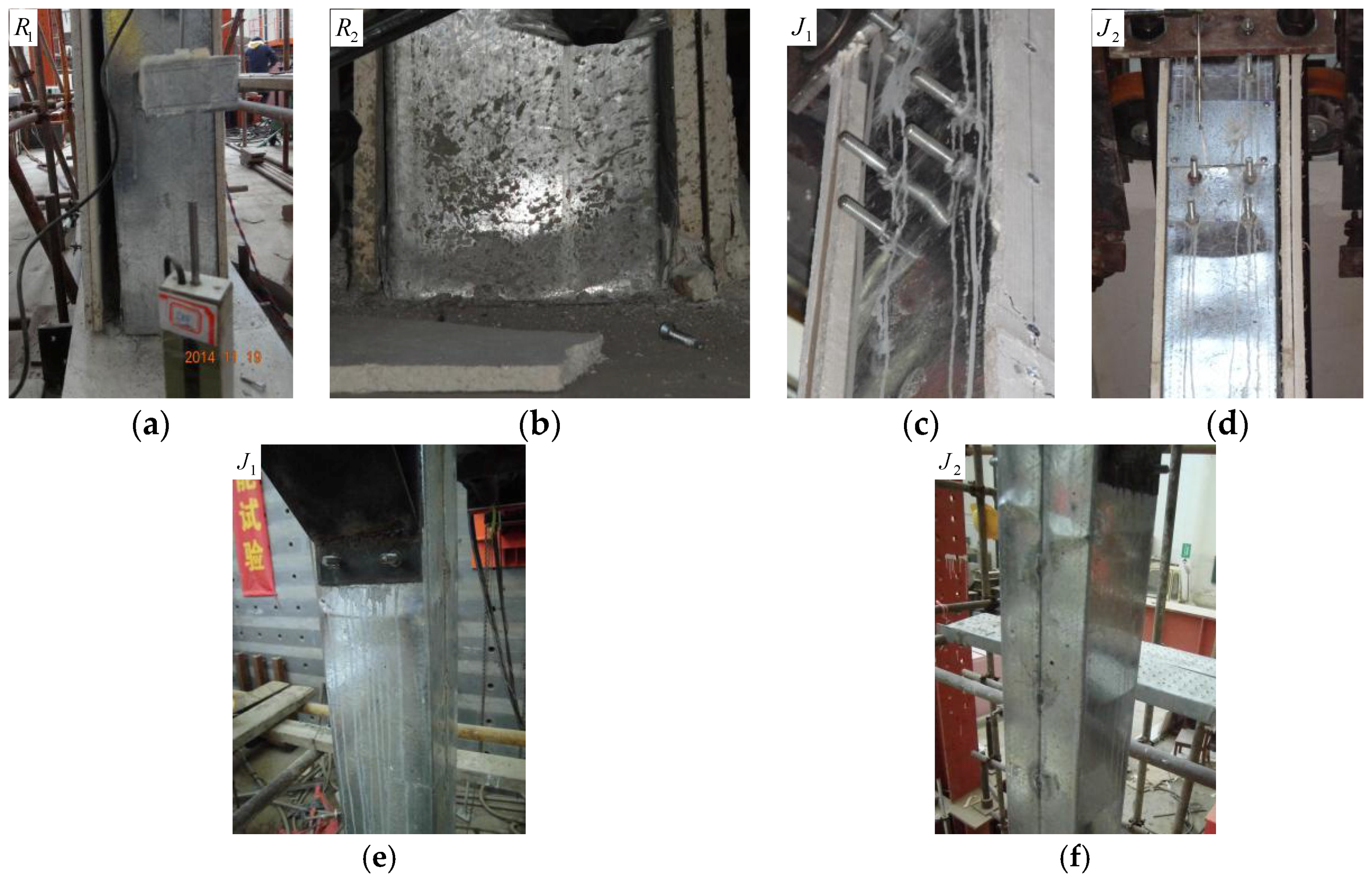
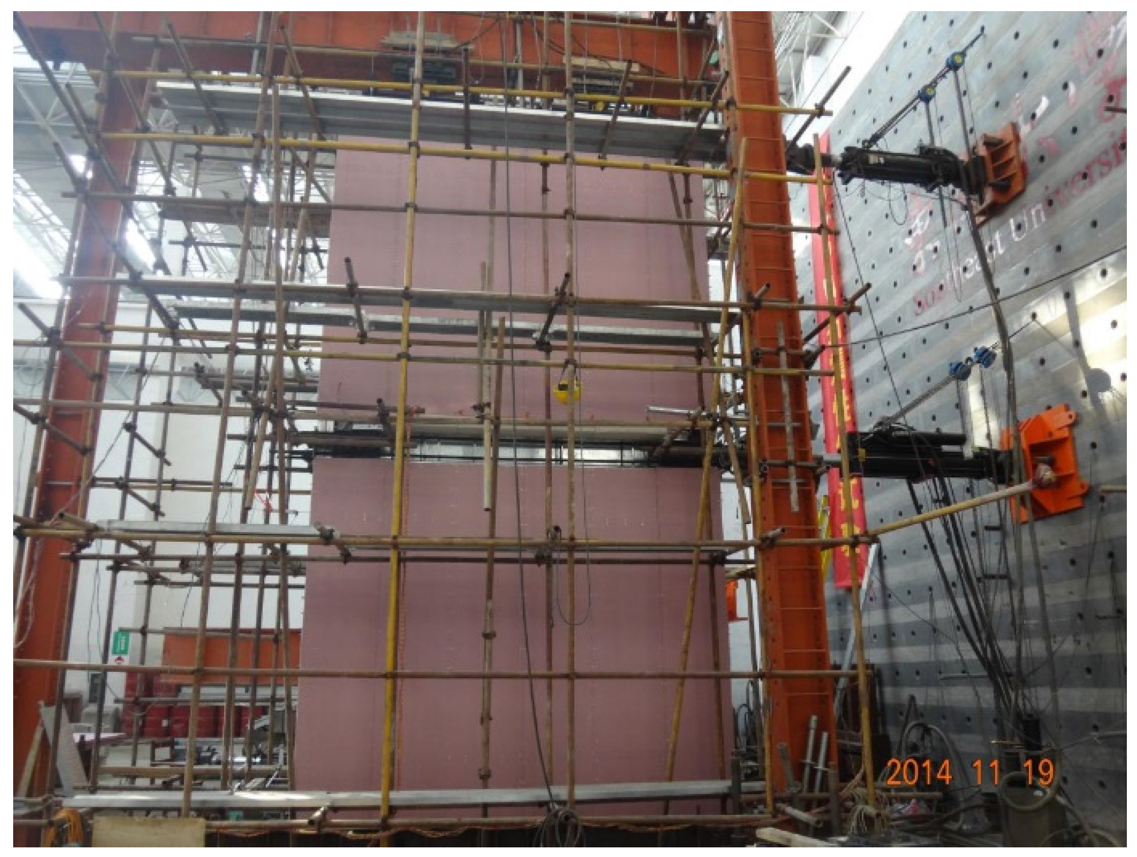
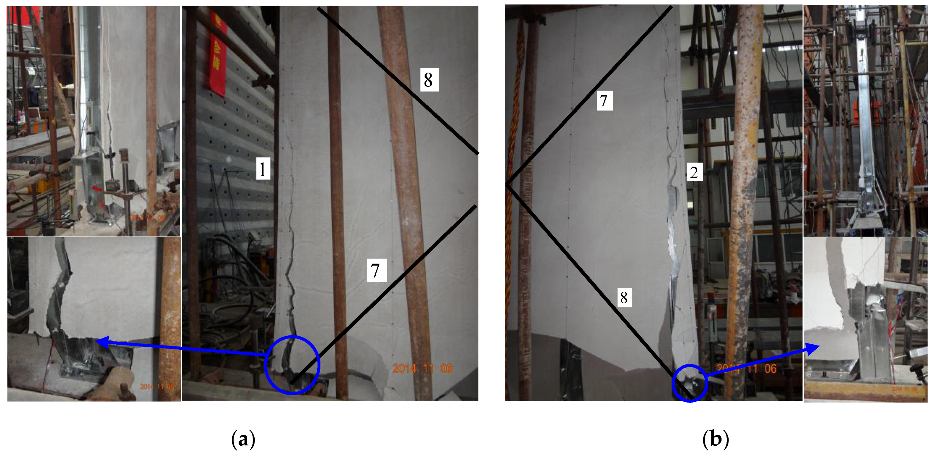
- Compared with test results, the vulnerability analysis method accurately predicted the damage locations and collapse modes of the traditional and RCFS shear wall systems. It was indicated that the structural vulnerability method can effectively identify the weakness of the shear walls, thus the proposed method can be used to reveal the seismic failure mechanism of such shear walls.
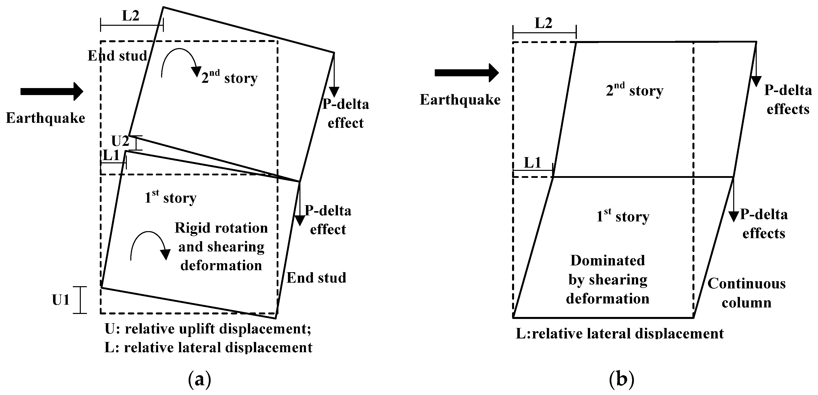
- For a two-story traditional CFS shear wall system, sheathing wallboards play a decisive role in the lateral resistance, and the structure would totally lose its lateral load-bearing capacity once the sheathing wallboards failed. For a RCFS shear wall system with end studs having sufficient stiffness, the collapse resistance of the whole structure can be effectively enhanced by a second form of defense, which is provided by the framework integrated by beams and end studs under rigid connection conditions together with their rigid connections to the foundation. In the case of end studs with insufficient stiffness, the RCFS shear wall system may have a total collapse mode caused by end stud failure, which is disadvantageous to the collapse resistance of the structure.
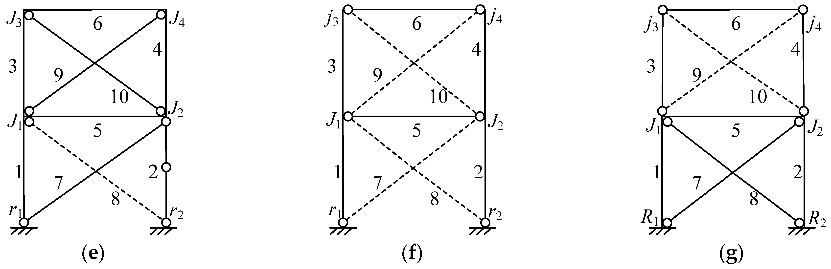
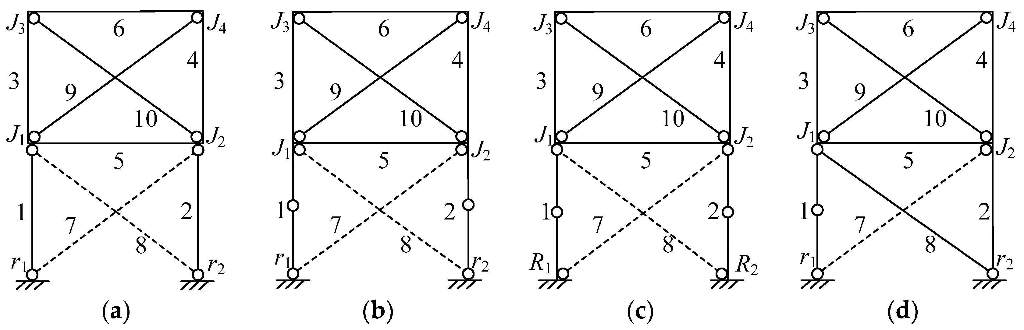
- According to the vulnerability indexes, it was shown that the RCFS shear wall system exhibits better structural robustness in comparison with the traditional one. In addition, to target the expected failure mode (this failure mode exhibits the lowest vulnerability in total collapse modes) presented in Figure 11f subjected to severe earthquakes, conceptional rules of “strong frame, weak wallboard” and “strong column, weak beam” were proposed for the seismic design of mid-rise RCFS structures.
Acknowledgments
Author Contributions
Conflicts of Interest
References
- Bae, S.W.; LaBoube, R.A.; Belarbi, A.; Ayoub, A. Progressive collapse of cold-formed steel framed structures. Thin-Walled Struct. 2008, 46, 706–719. [Google Scholar] [CrossRef]
- Hancock, G.J. Cold-formed steel structures: Research review 2013–2014. Adv. Struct. Eng. 2016, 19, 393–408. [Google Scholar] [CrossRef]
- Liu, P.; Peterman, K.D.; Schafer, B.W. Impact of construction details on OSB-sheathed cold-formed steel framed shear walls. J. Constr. Steel Res. 2014, 101, 114–123. [Google Scholar] [CrossRef]
- Zeynalian, M.; Ronagh, H.R. Seismic performance of cold formed steel walls sheathed by fiber-cement board panels. J. Constr. Steel Res. 2015, 107, 1–11. [Google Scholar] [CrossRef]
- Mowrtage, W. Cyclic lateral load behavior of CFS walls sheathed with different materials. Thin-Walled Struct. 2015, 96, 328–336. [Google Scholar] [CrossRef]
- Shamim, I.; DaBreo, J.; Rogers, C. Dynamic testing of single- and double-story steel-sheathed cold-formed steel-framed shear walls. J. Struct. Eng. 2013, 139, 807–817. [Google Scholar] [CrossRef]
- Ye, J.H.; Wang, X.X.; Jia, H.Y.; Zhao, M.Y. Cyclic performance of cold-formed steel shear walls sheathed with double-layer wallboards on both sides. Thin-Walled Struct. 2015, 92, 146–159. [Google Scholar] [CrossRef]
- Dao, T.N.; Van de Lindt, J.W. Seismic performance of an innovative light-frame cold-formed steel frame for midrise construction. J. Struct. Eng. 2013, 139, 837–848. [Google Scholar] [CrossRef]
- Mirzaei, A.; Sangree, R.H.; Velchev, K.; Comeau, G.; Balh, N.; Rogers, C.A.; Schafer, B.W. Seismic capacity-based design of narrow strap-braced cold-formed steel walls. J. Constr. Steel Res. 2015, 115, 81–91. [Google Scholar] [CrossRef]
- Fiorino, L.; Luorio, O.; Macillo, V.; Terracciano, M.T.; Pali, T.; Landolfo, R. Seismic design method for CFS diagonal strap-braced stud walls: Experimental validation. J. Struct. Eng. 2016, 142, 04015154. [Google Scholar] [CrossRef]
- Zeynalian, M.; Ronagh, H.R. An experimental investigation on the lateral behavior of knee-braced cold-formed steel shear walls. Thin-Walled Struct. 2012, 51, 64–75. [Google Scholar] [CrossRef]
- Eom, T.S.; Ha, T.H.; Cho, B.H.; Kim, T.H. Cyclic loading tests on framed stud walls with strap braces and steel sheathing. J. Struct. Eng. 2015, 141, 04014173. [Google Scholar] [CrossRef]
- Wang, X.X.; Ye, J.H. Reversed cyclic performance of cold-formed steel shear walls with reinforced end studs. J. Constr. Steel Res. 2015, 113, 28–42. [Google Scholar] [CrossRef]
- Sabbagh, A.B.; Petkovski, M.; Pilakoutas, K.; Mirghaderi, R. Experimental work on cold-formed steel elements for earthquake resilient moment frame buildings. Eng. Struct. 2013, 42, 371–386. [Google Scholar] [CrossRef]
- Qin, Y.; Chen, Z.H. Research on cold-formed steel connections: A state-of-the-art review. Steel Compos. Struct. 2016, 20, 21–41. [Google Scholar] [CrossRef]
- Attari, N.K.A.; Alizadeh, S.; Hadidi, S. Investigation of CFS shear walls with one and two-sided steel sheathing. J. Constr. Steel Res. 2016, 122, 292–307. [Google Scholar] [CrossRef]
- Wang, X.X.; Ye, J.H. Cyclic testing of two- and three-story CFS shear-walls with reinforced end studs. J. Constr. Steel Res. 2016, 121, 13–28. [Google Scholar] [CrossRef]
- Tao, Z.; Han, L.H.; Wang, D.Y. Strength and ductility of stiffened thin-walled hollow steel structural stub columns filled with concrete. Thin-Walled Struct. 2008, 46, 1113–1128. [Google Scholar] [CrossRef]
- Tao, Z.; Uy, B.; Han, L.H.; Wang, Z.B. Analysis and design of concrete-filled stiffened thin-walled steel tubular columns under axial compression. Thin-Walled Struct. 2009, 47, 1544–1556. [Google Scholar] [CrossRef]
- Retamales, R.; Davies, R.; Mosqueda, G.; Filiatrault, A. Experimental seismic fragility of cold-formed steel framed gypsum partition walls. J. Struct. Eng. 2013, 139, 1285–1293. [Google Scholar] [CrossRef]
- Wang, X.; Pantoli, E.; Hutchinson, T.C.; Restrepo, J.I.; Wood, R.L.; Hoehler, M.S.; Grzesik, P.; Sesma, F.H. Seismic performance of cold-formed steel wall systems in a full-scale building. J. Struct. Eng. 2015, 141, 04015014. [Google Scholar] [CrossRef]
- Jenkins, C.; Soroushian, S.; Rahmanishamsi, E.; Maragakis, E.M. Experimental fragility analysis of cold-formed steel steel-framed partition wall systems. Thin-Walled Struct. 2016, 103, 115–127. [Google Scholar] [CrossRef]
- Dubina, D. Structural analysis and design assisted by testing of cold-formed steel structures. Thin-Walled Struct. 2008, 46, 741–764. [Google Scholar] [CrossRef]
- Peter, K.D.; Stehman, M.J.J.; Buonopane, S.G.; Nakata, R.L.M.; Schafer, B.W. Seismic performance of full-scale cold-formed steel buildings. In Proceedings of the 10th National Conference on Earthquake Engineering, Anchorage, AK, USA, 21–25 July 2014; EERI: Oakland, CA, USA, 2014. [Google Scholar]
- Ozaki, F.; Kawai, Y.; Kanno, R.; Hanya, K. Damage-control systems using replaceable energy-dissipating steel fuses for cold-formed steel structures: Seismic behavior by shake table tests. J. Struct. Eng. 2013, 139, 787–795. [Google Scholar] [CrossRef]
- Wu, X.; Blockley, D.I.; Woodman, N.J. Vulnerability analysis of structural systems part I: Rings and clusters. Civ. Eng. Syst. 1993, 10, 301–317. [Google Scholar] [CrossRef]
- Wu, X.; Blockley, D.I.; Woodman, N.J. Vulnerability analysis of structural systems part II: Failure scenarios. Civ. Eng. Syst. 1993, 10, 319–333. [Google Scholar] [CrossRef]
- Agarwal, J.; Blockley, D.I.; Woodman, N.J. Vulnerability of 3-dimensional trusses. Struct. Saf. 2001, 23, 203–220. [Google Scholar] [CrossRef]
- Agarwal, J.; Blockley, D.I.; Woodman, N.J. Vulnerability of structural system. Struct. Saf. 2003, 25, 263–286. [Google Scholar] [CrossRef]
- Murta, A.; Pinto, J.; Varum, H. Structural vulnerability of two traditional Portuguese timber structural systems. Eng. Fail. Anal. 2011, 18, 776–782. [Google Scholar] [CrossRef]
- Ye, J.H.; Liu, W.Z.; Pan, R. Research on failure scenarios of domes based on form vulnerability. Sci. China Ser. E 2011, 54, 2834–2853. [Google Scholar] [CrossRef]
- Zhu, N.H.; Ye, J.H. Structural vulnerability of a single-layer dome based on its form. J. Eng. Mech. 2014, 140, 112–127. [Google Scholar]
- Liu, W.Z.; Ye, J.H. Collapse optimization for domes under earthquake using a genetic simulated annealing algorithm. J. Constr. Steel Res. 2014, 97, 59–68. [Google Scholar] [CrossRef]
- Japan Iron and Steel Federation. Design Guide for Light Gauge Steel Buildings; Gihodo Shuppan Co. Ltd.: Tokyo, Japan, 2002. [Google Scholar]
- Fülöp, L.A.; Dubina, D. Performance of wall-stud cold-formed shear panels under monotonic and cyclic loading: Part II: Numerical modelling and performance analysis. Thin-Walled Struct. 2004, 42, 339–349. [Google Scholar] [CrossRef]
- Dubina, D. Behavior and performance of cold-formed steel-framed houses under seismic action. J. Constr. Steel Res. 2008, 64, 896–913. [Google Scholar] [CrossRef]


| Member | Section Type (mm) | Length (m) | EA (N) | EI (N·m2) |
|---|---|---|---|---|
| End stud | Coupled C89 × 100 × 0.9 a (W1) | All are 3.0 | 7.830 × 10⁷ | 5.254 × 10⁴ |
| □140 × 140 × 13 × 1.5 b (W2) | 2.467 × 10⁸ | 3.287 × 10⁵ | ||
| □89 × 100 × 13 × 0.9 c (W2-1) | 9.952 × 10⁷ | 1.260 × 10⁵ | ||
| Beam | Coupled C89 × 100 × 0.9 d | 3.6 | 7.830 × 10⁷ | 1.031 × 10⁵ |
| Sheathing (equivalent bracing) | 12 mm BMB for the base layer, 12 mm BMB along with 12 mm GWB for the face layer (W1 and W2) | All are 4.686 | 6.208 × 10⁶ | |
| 12 mm BMB along with 12 mm GWB for both the base and the face layers (W2-1) | 9.531 × 10⁶ | |||
| Track | U91 × 50 × 0.9 (W1 and W2-1) | Ignoring their contribution to the global stiffness, only the connection function was considered. | ||
| U142 × 50 × 1.5 (W2) | ||||
| Collapse Mode | Failure Mode | Separateness γ | Relative Damage Demand Dr | Vulnerability Index φ |
|---|---|---|---|---|
| Total collapse mode | Figure 8a | 1.0 | 0.1581 | 6.325 |
| Figure 8b | 1.0 | 0.1949 | 5.131 | |
| Figure 8c | 1.0 | 0.2614 | 3.826 | |
| Local collapse mode | Figure 8d | 0.355 | 0.1581 | 2.246 |
| Collapse Mode | Failure Mode | Separateness γ | Relative Damage Demand Dr | Vulnerability Index φ |
|---|---|---|---|---|
| Total collapse mode | Figure 11a | 1.0 | 0.2088 | 4.789 |
| Figure 11b | 1.0 | 0.3666 | 2.728 | |
| Figure 11c | 1.0 | 0.3992 | 2.505 | |
| Figure 11d,e | 1.0 | 0.2345 | 4.264 | |
| Figure 11f (Expected mode) | 1.0 | 0.4535 | 2.205 | |
| Local collapse mode | Figure 11g | 0.813 | 0.2631 | 3.089 |
© 2017 by the authors. Licensee MDPI, Basel, Switzerland. This article is an open access article distributed under the terms and conditions of the Creative Commons Attribution (CC BY) license ( http://creativecommons.org/licenses/by/4.0/).
Share and Cite
Ye, J.; Jiang, L.; Wang, X. Seismic Failure Mechanism of Reinforced Cold-Formed Steel Shear Wall System Based on Structural Vulnerability Analysis. Appl. Sci. 2017, 7, 182. https://doi.org/10.3390/app7020182
Ye J, Jiang L, Wang X. Seismic Failure Mechanism of Reinforced Cold-Formed Steel Shear Wall System Based on Structural Vulnerability Analysis. Applied Sciences. 2017; 7(2):182. https://doi.org/10.3390/app7020182
Chicago/Turabian StyleYe, Jihong, Liqiang Jiang, and Xingxing Wang. 2017. "Seismic Failure Mechanism of Reinforced Cold-Formed Steel Shear Wall System Based on Structural Vulnerability Analysis" Applied Sciences 7, no. 2: 182. https://doi.org/10.3390/app7020182