
An IoT System for Remote Monitoring of Patients at Home

Computer Engineering Department, Keimyung University, Daegu, 42601, Korea
*
Author to whom correspondence should be addressed.
Appl. Sci. 2017, 7(3), 260; https://doi.org/10.3390/app7030260
Submission received: 18 December 2016
/
Revised: 14 February 2017
/
Accepted: 1 March 2017
/
Published: 8 March 2017
(This article belongs to the Special Issue Smart Healthcare)
Abstract
:Application areas that utilize the concept of IoT can be broadened to healthcare or remote monitoring areas. In this paper, a remote monitoring system for patients at home in IoT environments is proposed, constructed, and evaluated through several experiments. To make it operable in IoT environments, a protocol conversion scheme between ISO/IEEE 11073 protocol and oneM2M protocol, and a Multiclass Q-learning scheduling algorithm based on the urgency of biomedical data delivery to medical staff are proposed. In addition, for the sake of patients’ privacy, two security schemes are proposed—the separate storage scheme of data in parts and the Buddy-ACK authorization scheme. The experiment on the constructed system showed that the system worked well and the Multiclass Q-learning scheduling algorithm performs better than the Multiclass Based Dynamic Priority scheduling algorithm. We also found that the throughputs of the Multiclass Q-learning scheduling algorithm increase almost linearly as the measurement time increases, whereas the throughputs of the Multiclass Based Dynamic Priority algorithm increase with decreases in the increasing ratio.
1. Introduction
The concept of IoT (Internet of Things) [1,2], which allows smart objects to communicate with each other or with a user, has become increasingly popular. With an IoT, we can obtain much more information more easily than ever before, and control objects much more seamlessly. The IoT concept can be applied in many areas, including metering, traffic control, smart homes, and building management. The objects can be sensors, home equipment, meters, and other similar devices.
The remote monitoring of patients has become a highly active area of research in recent years [3,4,5,6,7,8,9]. However, there has not been much research on remote monitoring that employs the IoT concept. Application areas that utilize the concept of IoT can be broadened to healthcare or remote monitoring areas. Personal Healthcare Devices (PHDs) are portable electronic healthcare devices that sense and measure users’ biomedical signals. Activity monitors, medication dispensers, pulse oximeters, ECG monitors, blood pressure monitors and falling detectors are representative examples of PHDs [10,11,12,13,14,15]. PHDs could be objects in an IoT system for health care, and healthcare workers could enjoy most of the advantages of an IoT system by monitoring patients at home via IoT systems.
In this paper, an IoT system for the remote monitoring of patients at home is proposed. With the help of the IoT system for monitoring patients at home, medical staffs can monitor their patients at home much more easily than ever before by receiving diverse biomedical data from PHDs with which the patients are connected. PHDs are considered as objects in the IoT system in this paper, and the system will enable medical staffs to be informed when their patients experience emergency conditions more quickly than ever before. In this study, the IoT monitoring system is proposed and constructed based on the oneM2M (one Machine-to-Machine) communication protocol [16,17,18], an international communication protocol standard for IoT systems.
To make the patient at home monitoring system more desirable and operable on ordinary IoT networks, we consider the following issues in this paper.
- Multiclass data scheduling/communication: Because many diverse PHDs and their biomedical data are transmitted to medical staffs, each piece of data needs to be classified based on the urgency of its delivery. More urgent of data deliveries are assigned higher classes. For example, falling detector data have to be delivered more urgently than medication dispenser data, and thus falling detector data are assigned to the higher class. Alarm conditions should be assigned to the highest class. For example, abnormal ECG data are assigned to a higher class than normal ECG data, and should be delivered more quickly.
- Communication protocol conversion: To use PHDs as objects in an IoT system based on the oneM2M protocol, a communication protocol conversion process is needed, as PHDs and IoT systems use different standard communication protocols. In other words, the ISO/IEEE 11073 protocol [10,11] is an international standard for PHD communication, while the oneM2M protocol is an international standard for the IoT system considered in this paper.
- Strict authorization: Because the biomedical data obtained by a PHD may involve a patient’s privacy, the data need to be handled in a manner that prevents its exposure to unauthorized persons. In this study, two security schemes are proposed. First, a patient’s biomedical data obtained by a PHD are not stored as a single unit, but stored in parts in the IoT server. The data are partitioned into several parts (two parts in this study) and stored separately in the IoT server. Furthermore, the separation information is not stored in the IoT server, but in the IoT authentication server. This means that anyone who wants to access the data has to access both the IoT server and the IoT authentication server at the same time. Second, an authentication scheme called the Buddy-ACK (Acknowledgment) authorization scheme is proposed in this study. In the Buddy-ACK authorization scheme, a specific piece of biomedical data can be accessed only after both a patient and the related medical staff are authorized. We call the patient and the related medical staff “buddies”. A piece of biomedical data can be accessed only after the acknowledgement (or consent) of the buddy is obtained.
The remainder of this paper is organized as follows. Section 2 describes some related studies, and Section 3 explains the structure of the monitoring IoT system for patients at home proposed in this paper. Section 4 discusses the multiclass Q-learning scheduling algorithm proposed in this study, while Section 5 discusses communication protocol conversion mechanisms between oneM2M and ISO/IEEE 11073. Section 6 identifies some security issues and describes the Buddy-ACK authentication scheme proposed in this study. Section 7 shows the results of some experiments using the system constructed in this study, and engages in a discussion based on the results. Finally, Section 8 draws some conclusions and discusses some possible directions for future research.
2. Related Studies
In [12,13,14,15], web-based remote PHD management systems for activity monitors, a medication dispenser, and pulse oximeters were proposed and constructed. In terms of communication protocols, ISO/IEEE 11073 and OMA DM (Open Mobile Alliance Data Management) protocols were used to transmit measured data or remote commands. Gateways located between PHDs and the management server transform the ISO/IEEE 11073 messages into OMA DM messages, and vice versa. Biomedical data measured by PHDs were transmitted in an FCFS (First Come, First Served) manner, and there were neither message classification in data scheduling/transmission, nor data security in data access.
Clinician focused remote monitoring systems for telehealth can be found in [3,4,5,6,7,8,9]. In the telehealth system shown in [8], wireless wristwatch-based monitoring devices are attached to elderly patients to continuously collect their temperature and motion data. It was found that the designed health monitoring system can be used for an extended period of time and may help older patients with chronic conditions reside in their own homes for longer. In [3,5], it was found that tortuosity in movement paths by elderly persons was related to cognitive impairment or contributed to an increased fall prediction. Four sensors were installed at each corner of a gathering place in an assisted living facility, to wirelessly sense the location data of tags attached to participants. The location data were used to calculate movement path variability. Even though the data processing and transmission methods used in these studies were not clearly addressed, it seems that the data were transmitted in an FCFS manner, and there was no message classification in data scheduling/transmission. Data security in data access was not mentioned either.
Protocol conversion has been used when there are more than two different communication protocols in a system, or when two systems with different communication protocols need to be connected. In [19], a formal model for protocol conversion was presented. The construction of protocol converters was illustrated also. Protocol conversion between wireless sensors (Lean Transport Protocol) and Web systems (Hyper Text Transfer Protocol) was proposed to extend a Web service oriented architecture to wireless sensors for a Web of Things [20]. In particular, self-description of embedded Web services was proposed through the efficient compression of WSDL documents. Backend IT systems can invoke embedded Web services on sensor nodes and vice versa by providing an open framework for protocol conversion. Protocol conversion between SIP (Session Initiation Protocol) and SOAP (Simple Object Access Protocol) can be found in [21]. This proposes a generic SIP/SOAP gateway that implements message handling and network and storage management while relying on application-specific converters to define session management and message mapping for a specific set of SIP and SOAP communication nodes. Thus far, few studies have proposed protocol conversion between ISO/IEEE 11073 protocol and oneM2M protocol, which we propose in this paper.
Security issues for IoT systems or mobile devices have been addressed in many papers [22,23,24,25,26,27,28]. In particular, Mohamed et al. [23] proposed a game-based model for adaptive security in the IoT, with an emphasis on eHealth applications. For the sake of mobile devices, the tradeoff between security-effectiveness and energy-efficiency to evaluate adaptive security strategies was considered also. Authentication is to identify users to enable services for legitimate users only, and is considered one of the key aspects of security issues. Biometric authentication [25,26,27,28] has been the most popular method for individual identification. Biometric authentication involves the comparison of an input data with stored biometric data to identify a specific user. Fingerprints, face recognition, hand geometry and iris recognition, and ECG are some examples of this type of biometric authentication. Thus far, few studies have proposed the participation of users and the related medical staff in the process of authentication that we propose in this paper.
Multiclass scheduling can be performed when various data to be scheduled have different characteristics [29,30]. The Multiclass Based Dynamic Priority (MBDP) scheduling algorithm [30] classifies messages used for M2M communication in LTE environments into four types: very small-sized delay-intolerant messages (Type 1), messages requiring a minimum guaranteed bit rate (Type 2), bulk-sized delay-tolerant messages (Type 3), and very small-sized delay-tolerant messages (Type 4). Type 1 messages are classified as class 1 and their delay times are 0. Type 3 and Type 4 messages are classified into class N and their delay times are infinite. Communication resources are assigned to class 1 messages first and subsequently assigned to class 2 messages through class N messages. Thus far, few studies have focused on multiclass scheduling for biometric data with the concept of Q-learning.
3. Structure of the Patient at Home Monitoring IoT System
Figure 1 shows the structure of the IoT system for monitoring patients at home that is proposed in this paper. To prepare for the massive number of Personal Healthcare Devices (PHDs) needed, the system was designed as multilayered. The system consists of Application Dedicated Nodes—Application Entities (ADN-AEs), Middle Nodes—Common Service Entities (MN-CSEs), the Infrastructure Node—Common Service Entity (IN-CSE), and Infrastructure Nodes—Application Entities (IN-AEs).
An ADN-AE is a program installed in a sensor. It senses neighboring signals, processes them to generate data, and finally sends the data to the IN-CSE installed on the patient monitoring IoT server. A (program on a) PHD acts as an ADN-AE in the proposed system. Through an IoT network, MN-CSEs function as gateways for traffic control and/or protocol conversion. In this paper, they transmit patients’ biomedical data obtained by a PHD to the IN-CSE (the patient monitoring IoT server). Medical staff or system managers use IN-AEs to access the patients’ data stored in the IoT server. An MN-CSE controls or monitors ADN-AEs that belong to the MN-CSE; moreover, it performs processing that is necessary to achieve efficient multiclass communication between ADN-AEs and the IN-CSE. An IN-AE can access patients’ data by accessing the patient monitoring IoT server via an IoT network.
In the IoT system, a large amount of diverse biomedical data are transmitted from PHDs to a gateway, and it takes a non-negligible amount of transmission time for the data to be delivered to the patient monitoring IoT server or medical staffs. Therefore, alarm signals that represent abnormal conditions of the patients should be delivered (or “pushed”) more quickly than any other data. One of the gateway’s responsibilities is to classify and prioritize data received from PHDs, and schedule their data transmissions based on their priorities.
In this study, the oneM2M-based IoT system is constructed in accordance with the oneM2M specifications [16,17]. Then, two modules (Protocol Converter module and MQL Scheduler module) are added, as shown in Figure 2. An ADN-AE consists of a Sensing module and a Network Manager module. The Sensing module senses the biomedical signals of PHD users and processes them to generate biomedical data. The biomedical data are delivered to the Network Manager module, where oneM2M messages are made based on the received biomedical data. A CSE consists of a Network Manager module, a Message Handler module, and a Resource Manager module. The Network Manager module deals with communication with ADN-AEs and controls the entire CSE process. The Resource Manager module manages resource trees in which the information of every object the IoT system manages is stored.
The Network Manager module consists of NSE (Network Service Exposure), CMDH (Communication Management and Delivery Handling), NSSE (Network Service Exposure Execution and Triggering) and CSFs (Common Service Functions) Controller. In addition, MQL Scheduler is added for the multiclass Q-learning scheduling proposed in this study. The NSE module transmits oneM2M messages and the CMDH module manages communication (policies) and buffers. The NSSE module performs session management for connection between CSFs and NSE. The MQL Scheduler module makes scheduling decisions for biomedical data transmission on the base of the execution of the MQL scheduling algorithm, which will be discussed in the next section.
The Message Handler module consists of MessageHandler/Protocol Converter and ReferencePoint. The Message Handler module analyzes the incoming messages and performs message conversion between oneM2M primitive messages and HTTP messages. The ReferencePoint module processes XML documents and HTTP headers. The mapping between oneM2M Request/Response primitive messages and HTTP messages is shown in Table 1 and Table 2.
In this study, the Protocol Converter module is added to the MessageHandler module for protocol conversion between ISO/IEEE 11073 messages and oneM2M messages. The proposed protocol conversion mechanism will be discussed in Section 5.
The Resource Manager module consists of ResourceManager and FileHandler. The ResourceManager module performs operations (Create, Retrieve, Update, Delete) on resource trees, based on the received oneM2M primitive Request messages. It also stores the results of the operations in oneM2M primitive Response messages. The FileHandler module manages resource trees stored in physical data stores.
There are two different communication protocols used in the proposed system. The ISO/IEEE 11073 communication protocol is used between PHDs (ADN-AE) and gateways (MN-CSE) for PHD communication, and the oneM2M communication protocol is used between the patient monitoring IoT server (IN-CSE) and gateways for IoT networks. It is natural for the ISO/IEEE 11073 communication protocol to be used for PHD-gateway communication in this paper because the protocol is a standard communication protocol for PHD communication. Similarly, the oneM2M communication protocol is a standard communication protocol for IoT systems, and it is also reasonable that the oneM2M communication protocol is used for the IoT server-gateway communication in this paper. Otherwise, ordinary IoT servers that naturally support the oneM2M standard communication protocol would not understand the message sent from PHDs. As you know, standard communication protocols are used to enable interoperability between different machines or equipment. Therefore, one of the gateway’s responsibilities is to convert the ISO/IEEE 11073 protocol into the oneM2M protocol and vice versa to seamlessly transmit a patient’s biomedical data from a PHD to the IoT server.
4. Data Classification and Multiclass Q-Learning (MQL) Algorithm
In this study, PHDs such as activity monitors [12], medication dispensers [13], pulse oximeters [14], and ECG monitors, blood pressure monitors and falling detectors are considered as ADN-AEs in the IoT system for monitoring patients at home. For example, Alarm signals of abnormal SpO2 belong to the highest priority class (Urgent class), and thus are transmitted before any other data. In addition, the alarm signals of the Urgent class are pushed immediately to medical staffs even when the medical staffs do not request the related data from the patient monitoring IoT server.
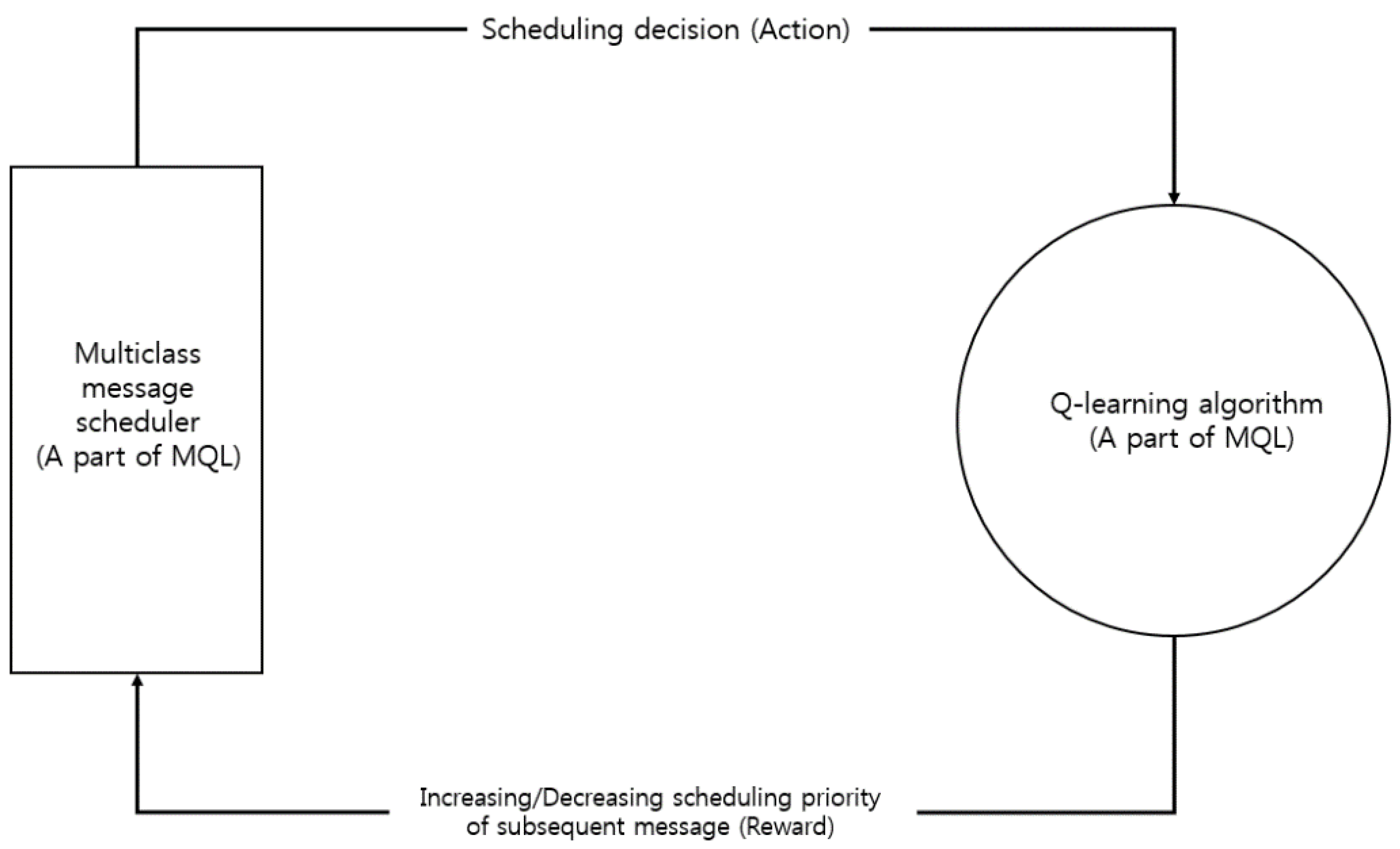
The multiclass Q-learning scheduling (MQL) algorithm proposed in this study is based on the Q-learning algorithm [31]. As shown in Figure 3, Q-learning is a reinforcement-based learning algorithm that finds an optimal policy by selecting the action with the highest reward in each state.
The proposed MQL algorithm evaluates the appropriateness of the previous scheduling decision (action); the evaluation result (reward) is then applied to the next scheduling decision. Based on the evaluation result, the scheduling priority of the subsequent message increases or decreases. If a non-urgent message is scheduled for transmission at time T1, and the message is transmitted successfully at T1 without interfering with the transmission of urgent messages, then the scheduling priority of the non-urgent message increases and subsequent non-urgent messages are likely to be scheduled to transmit at T1. Otherwise, the scheduling priority of the non-urgent message decreases and subsequent non-urgent messages are not likely to be scheduled to transmit at time T1. Through successive scheduling decisions, evaluations and applications, the algorithm determines optimal scheduling decisions. The MQL algorithm is designed to transmit urgent messages immediately and transmit non-urgent messages later, when they will not interfere with urgent message transmissions.
When a message arrives for scheduling, the message is inserted into its queue as shown in Algorithm 1 (Insertion of newly arrived message into its queue) discussed below. UrgentQ[*] is a priority queue in which urgent messages wait for scheduling based on their priority basis. NonUrgentQ[t, *] is a priority queue in which non-urgent messages arriving at unit time t wait for scheduling based on their priority basis (1 ≤ t ≤ T; T is the number of unit times). If messages are scheduled every hour (every half hour) for 24 h, T is 24 (48).
| Algorithm 1. Insertion of newly arrived message into its queue |
| For a newly arrived urgent message NewM; |
| Insert NewM at the appropriate position in UrgentQ[*] based on message’s |
| priority basis |
| For an existing message OldM whose priority is lower than NewM’s priority and therefore is pushed back by one position in UrgentQ[*]: |
| Increase OldM’s priority by AGED |
| (AGE: an aging constant, 0.9 in this study, |
| D: the distance between the positions of NewM and OldM) |
| For the newly arrived non-urgent message NewM at unit time At: |
| Find QTable[At, k] for the maximum reward in QTable[At, *] (1 ≤ k ≤ T) |
| Insert NewM at the appropriate position in NonUrgentQ[k, *] based on message’s priority basis |
| For an existing message OldM whose priority is lower than NewM’s priority and therefore is pushed back by one position in NonUrgentQ[k, *]: |
| Increase OldM’s priority by AGED |
For example, suppose that a new urgent message UM3 (priority 5) arrives at UrgentQ[*] and that two urgent messages UM1 (priority 3) and UM2 (priority 1) are waiting in UrgentQ[*]. Then, UM3, UM1, and UM2 are located at the first, second, and third positions in UrgentQ[*], respectively, based on their priorities. Because UM1 and UM2 are existing messages and are pushed back by one position in UrgentQ[*] owing to the arrival of UM3, their priorities are increased to 3.9 (=3 + 0.91) and 1.81 (=1 + 0.92), respectively. The priority increase is a type of aging technique that prevents a message with a lower priority from suffering indefinite postponement.
The explanation for a non-urgent message is more complicated. First, by looking at Qtable[*, *], the algorithm finds the QTable[At, k] that obtains the maximum reward in QTable[At, *] to select the transmission time of a non-urgent message whose arrival unit time is At. QTable[At, j] contains the reward obtained when a non-urgent message whose arrival time is unit time At is actually scheduled to transmit at unit time j. The message is then inserted in NonUrgentQ[k, *]. The remainder of the explanation is similar to that of the urgent message case, and has been omitted here.
At unit time t, urgent messages in UrgentQ[*] are scheduled to transmit immediately. However, non-urgent messages in NonUrgentQ[t, *] cannot be scheduled to transmit when UrgentQ[*] is not empty. Therefore, an attempt to transmit a non-urgent message is rewarded negatively and Qtable[*, *] is updated appropriately. Conversely, an attempt to transmit a non-urgent message when UrgentQ[*] is empty is rewarded positively. Algorithm 2 (Transmission scheduling algorithm for non-urgent messages) explains the transmission scheduling algorithm for non-urgent messages.
| Algorithm 2. Transmission scheduling algorithm for non-urgent messages |
| At current unit time Ct: |
| If urgent messages are waiting for scheduling in UrgentQ[*], |
| Then, transmit the front urgent message in UrgentQ[1] |
| QTable[At, Ct] = Qtable[At, Ct] * REC + NR |
| (At: arrival unit time of the transmitted urgent message, |
| REC: recency constant, 0.9 in this study, |
| NR: negative reward, −1 in this study) |
| If UrgentQ[*] is empty and non-urgent messages are waiting for |
| scheduling in NonUrgentQ[Ct, *], |
| Then, transmit the front non-urgent message in NonUrgentQ[Ct, 1] |
| QTable[At, Ct] = Qtable[At, Ct] * REC + PR |
| (At: arrival time of the transmitted non-urgent message, |
| PR: negative reward, +2 in this study) |
Let us suppose that Table 3 shows the contents of QTable[*, *] and message queues at unit time 5. When a non-urgent message M18 whose priority is 3.0 arrives at unit time 5, Algorithm 1 determines that QTable[5,9] is the optimum reward (=9.46). The algorithm then inserts M18 into NonUrgentQ[9,1] and the priority of the existing non-urgent message M09 is increased to 2.9. “M18/3.0” in the lower part of Table 3 indicates that a non-urgent message whose ID is 18 and priority is 3.0 is waiting at the front of NonUrgentQ[9, *].
Let us suppose it is unit time 9. At this time, messages in UrgentQ[*] and NonUrgentQ[9, *] are ready to be scheduled. Using Algorithm 2, an urgent message M17 in UrgentQ[1] is scheduled to transmit immediately. However, because NonUrgentQ[9, *] is not empty, the reward of QTable[5,9] is decreased to 7.51 (=Qtable[5,9] × 0.9 – 1). This means that, owing to the existence of the urgent messages scheduled at unit time 9, a non-urgent message whose arrival unit time is 5 is now less likely to be scheduled to transmit at unit time 9. If three urgent messages are transmitted successfully at unit time 9, the reward of QTable[5,9] will be decreased to 4.18. If there is still sufficient time to schedule a non-urgent message M18 to transmit at unit time 9 after the transmission of M17, M01, and M02, the reward of QTable[5,9] will be increased to 5.76.
5. Protocol Conversion in the IoT System
5.1. Protocol Conversion Modules
As mentioned earlier, in this study protocol conversion is performed between the ISO/IEEE 11073 protocol and the oneM2M protocol. Most PHDs use ISO/IEEE 11073 protocol for their communication because the protocol is a standard communication protocol for PHDs. In addition, most IoT servers and IoT gateways support oneM2M communication protocol for their communication because the protocol is a standard communication protocol for IoT environments. Therefore, protocol conversion between the ISO/IEEE 11073 protocol and the oneM2M protocol is required for interoperability.
Figure 4 shows the program modules for this study that were newly added to the original oneM2M system for the protocol conversion process. Protocol conversion between the ISO/IEEE 11073 protocol and the oneM2M protocol is performed in gateways (MN-CSEs) in the system. The protocol conversion module consists of three classes programmed in C# under a Windows 7 environment.
- PHDMessageManager class: Controls the entire flow of the protocol conversion process. It also receives incoming messages to the protocol conversion module and delivers the messages to the PHDMessageHandler.
- PHDMessageHandler class: Performs protocol conversion and sends its results to the ResourceTreeManager, the responsibility of which is to build resource trees for the gateway.
- PHDMessageTemplate class: Handles the templates of various ISO/IEEE 11073 messages. With the templates, the related messages can be built quickly and protocol conversion time can be shortened.
5.2. Protocol Conversion Cases
Table 4 shows the mapping between oneM2M protocol Request messages (right column) and ISO/IEEE 11073 protocol Request messages (left column). The mapping between response messages is similar, and for this reason a description of those is omitted here. In the table, an Association Request (ISO/IEEE 11073) message is converted into a Retrieve Request (oneM2M) message. A Present (Store Sensing Data) Request message is converted into two types of oneM2M messages (i.e., a Retrieve Request message and Update Request messages). Because a Present (Store Sensing Data) Request message can contain multiple biomedical sensing data items, Update Request messages are generated according to the number of sensed data items in the Present (Store Sensing Data) Request message. Before generating the Update Request messages, one Retrieve Request message is generated to access environmental information for the sensed data items. It is not necessary to perform a protocol conversion on the incoming Association Release Request message.
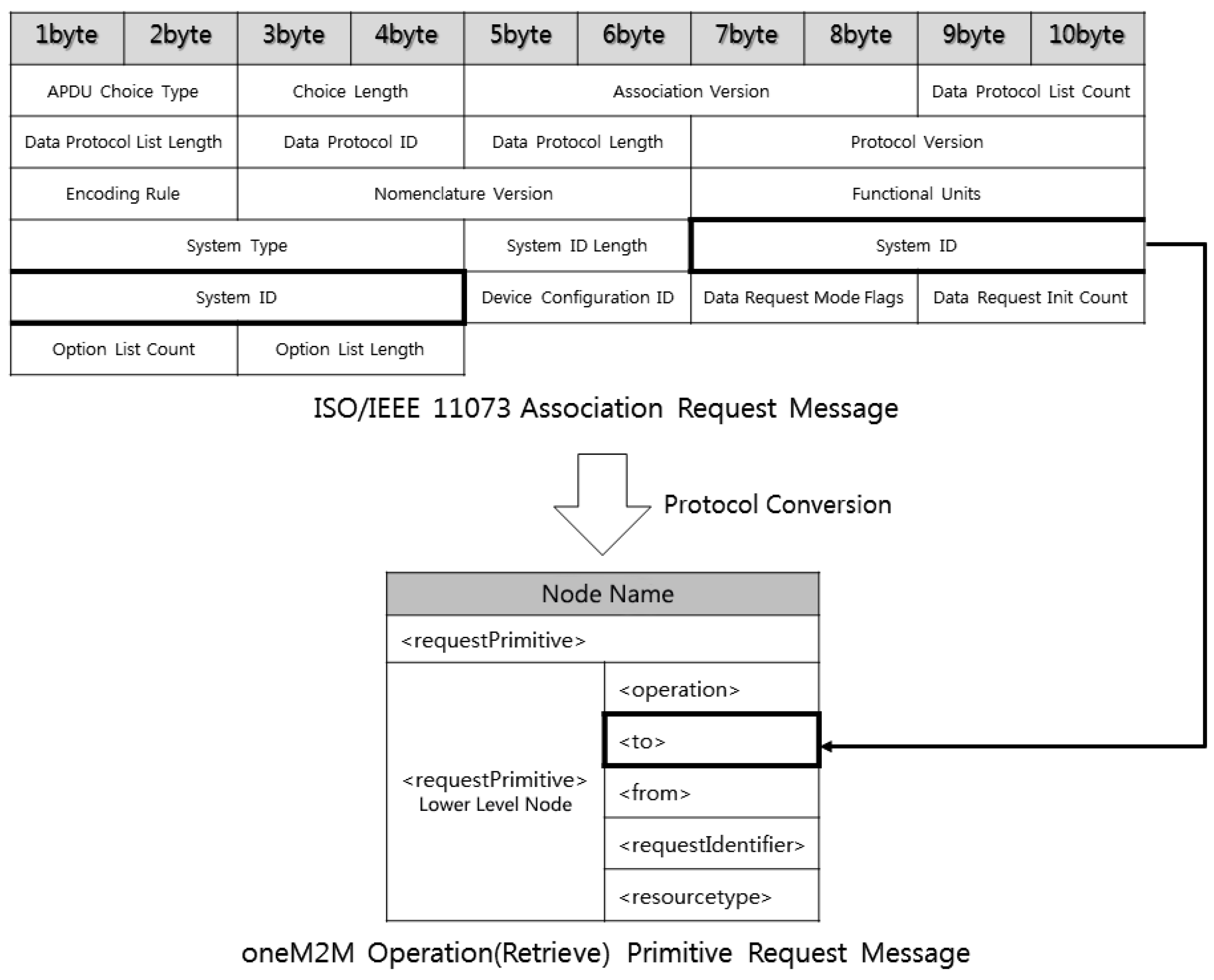
When a PHD wants to communicate, it initially sends an ISO/IEEE 11073 Association Request message to the other side. Figure 5 shows how to convert an ISO/IEEE 11073 Association Request message into a oneM2M Retrieve primitive Request message in a gateway (MN-CSE). Information related to the thick lines in the figure is involved in the protocol conversion process. In other words, the “System ID” field in the ISO/IEEE 11073 Association Request message is used to make the “<to>“ tag field in the oneM2M Retrieve primitive Request message. The “System ID” field is 8 bytes long and contains the identification number of the PHD (ADN-AE). Before building the oneM2M Retrieve primitive Request message, the gateway must check whether the PHD whose ID is in the “System ID” has been registered in the IoT server (IN-CSE) or the gateway. Information in the other fields in the ISO/IEEE 11073 Association Request message is saved for later use (i.e., building the related ISO/IEEE 11073 Association Response message which will be sent in the opposite direction).
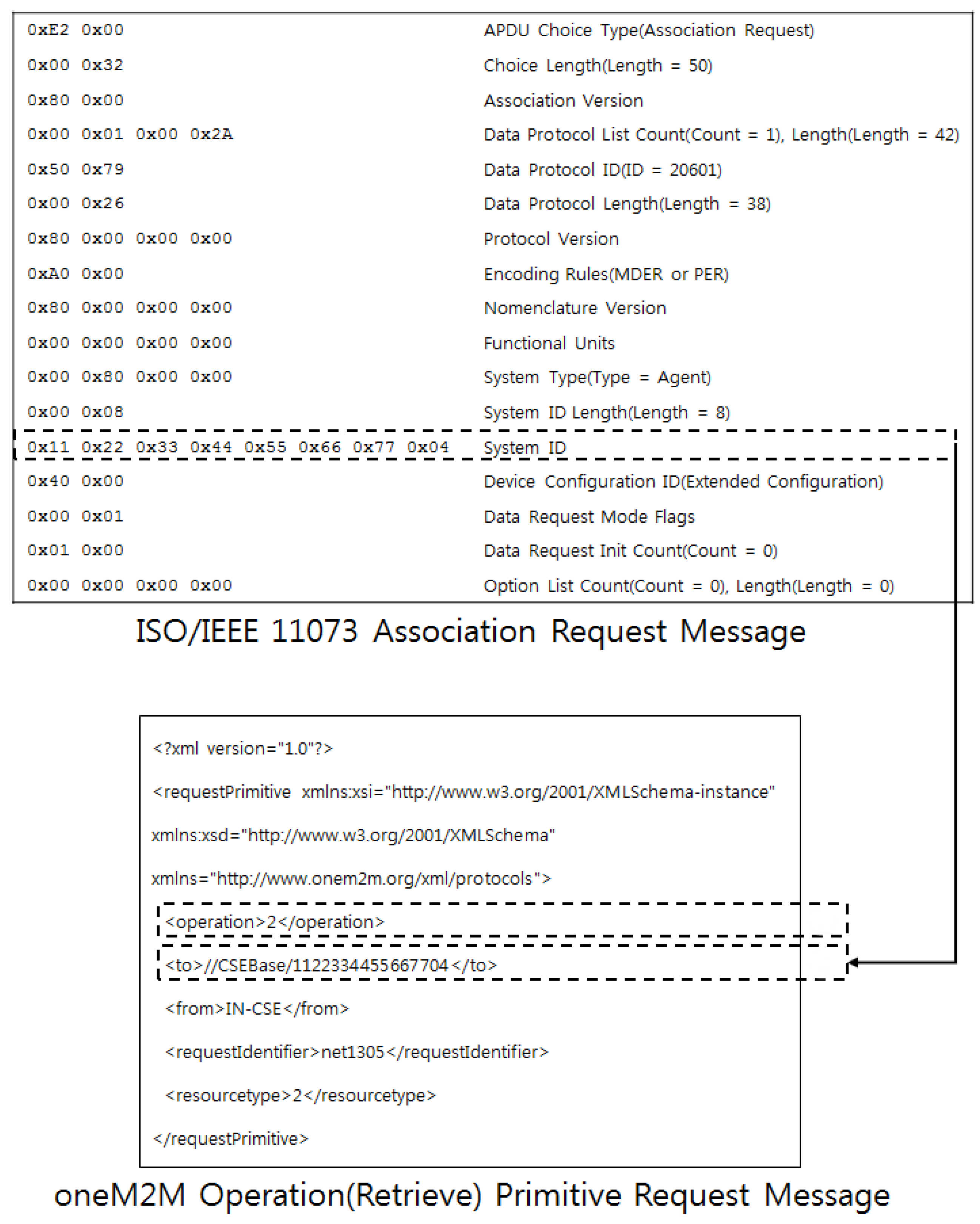
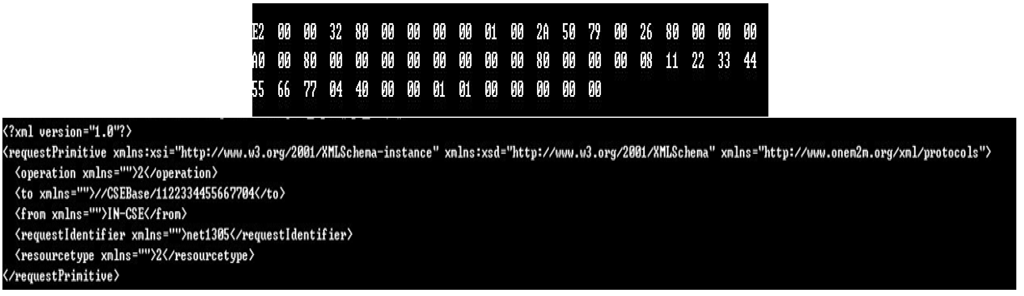
Figure 6 shows an example of the process shown in Figure 5. An ISO/IEEE 11073 Association Request message (i.e., a message before conversion) is represented in the upper box, while the resulting oneM2M Retrieve primitive Request message (i.e., a message after conversion) is in the lower box. From the first line of the ISO/IEEE 11073 Association Request message, the gateway knows that “APDU Choice Type” is 0xE2 0x00, which means this message is an ISO/IEEE 11073 Association Request message. “System Type” on the eleventh line is 0x00 0x80 0x00 0x00, which means that the PHD, the source of this message, is an agent. “System ID” of the PHD on the twelfth line is 0x11 0x22 0x33 0x44 0x55 0x66 0x77 0x04, which goes to the “<to>“ tag field in the resulting oneM2M Retrieve primitive Request message and it is represented in URL (“//CSEBase/1122334455667704”). Just above the “<to> tag, “<operation>“ tag must be defined and “2” is inserted, which means that this message is built for Retrieve operation.
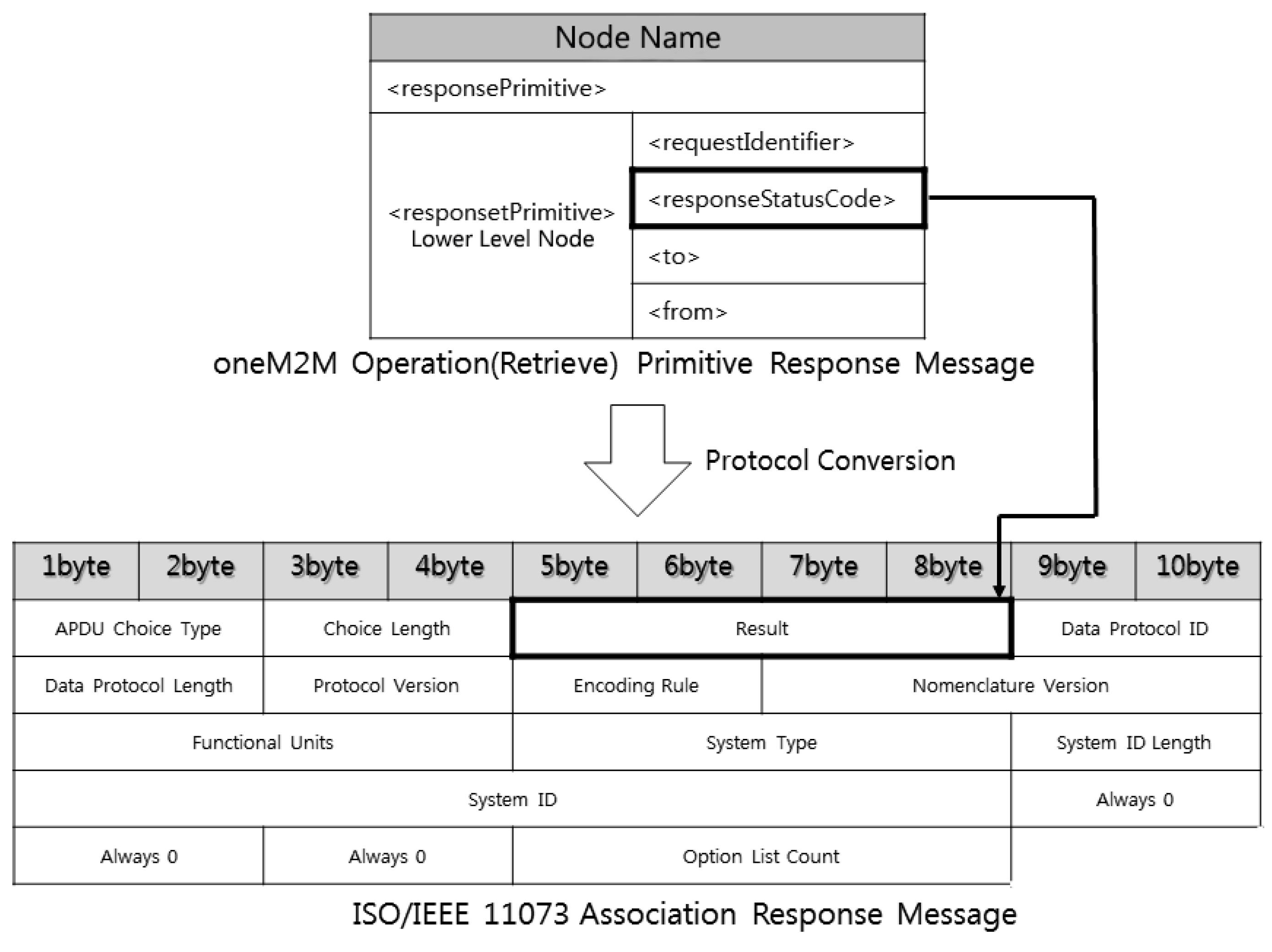
When the IoT server decides to communicate with the PHD, the server sends a oneM2M Retrieve primitive Response message. Figure 7 shows how to convert a oneM2M Retrieve primitive Response message into an ISO/IEEE 11073 Association Response message in the gateway. “<responseStatusCode>” tag field in the oneM2M Retrieve primitive Response message is used to make “Result” field in the ISO/IEEE 11073 Association Response message. The “<responseStatusCode>” field contains the results of the registration checking. An example of the process described in Figure 7 is omitted here.
When the PHD finds that it has not been registered in the IoT server after receiving the ISO/IEEE 11073 Association Response message sent from the gateway, the PHD sends an ISO/IEEE 11073 Present (Notice Configuration) Request message to inform the server of its environmental settings including biomedical data types the PHD will send. Figure 8 shows how to convert an ISO/IEEE 11073 Present (Notice Configuration) Request message into oneM2M Create primitive Request messages. Note that several oneM2M Create primitive Request messages are built from a single ISO/IEEE 11073 Present (Notice Configuration) Request message. This is because a single ISO/IEEE 11073 Present (Notice Configuration) Request message can contain multiple object information (“Object Class”, “Object Handle”, “Attribute Count”, “Attribute Length”, “Attribute ID”, “Attribute Value Length”, “Attribute Value”) and a oneM2M Create primitive Request message must be built for every piece of object information in a single ISO/IEEE 11073 Present (Notice Configuration) Request message. In Figure 8, each “Object Handle” field is used to create “<container>” node in the resource tree managed by the gateway or the IoT server. In addition, each (“Attribute ID”, “Attribute Value Length”, “Attribute Value”) is used to create a “<contentInstance>” tag node under the “<container>” tag node in the resource tree. For this paper, an explanation of the conversion of oneM2M Create primitive messages into an ISO/IEEE 11073 Present (Notice Configuration) Request message will be omitted.
Figure 9 and Figure 10 show examples of the process described in Figure 8. In Figure 9, “APDU Choice Type” on the first line is 0xE7 0x00, which means that this message is an ISO/IEEE 11073 Present Request message. “Event Type” on the ninth line indicates that this is a Notice Configuration message. “Configuration Object Count” (0x00 0x03) on the twelfth line indicates that the PHD sends the biomedical data of three objects. The lowest dotted box containing the fourteenth line to the last line represents the information of biomedical data to be delivered. Two more dotted boxes for additional objects are omitted here. In the dotted box, four pulse oximetry information including attributes are contained. Four pulse oximetry information delivered in Figure 9 needs to be stored in the appropriate places in the related resource tree. To store the value information, “<container>” and “<contentInstance>” tag nodes need to be created in the resource tree. In Figure 10, an example of the resulting oneM2M Create primitive Request messages is shown.
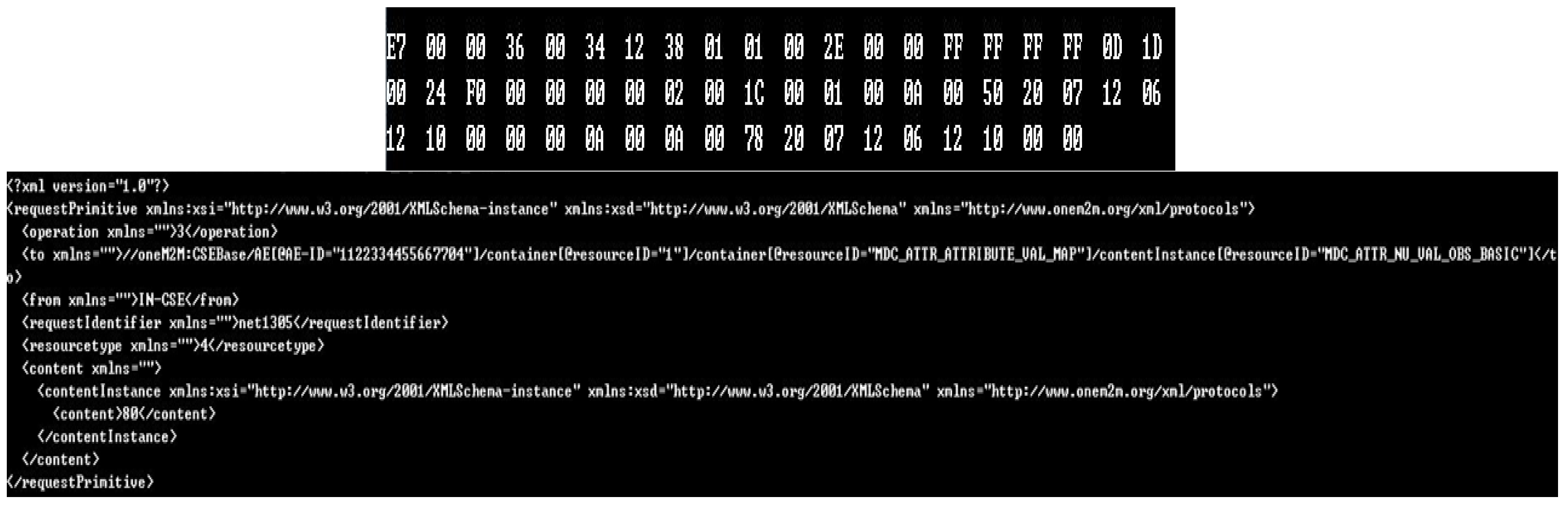
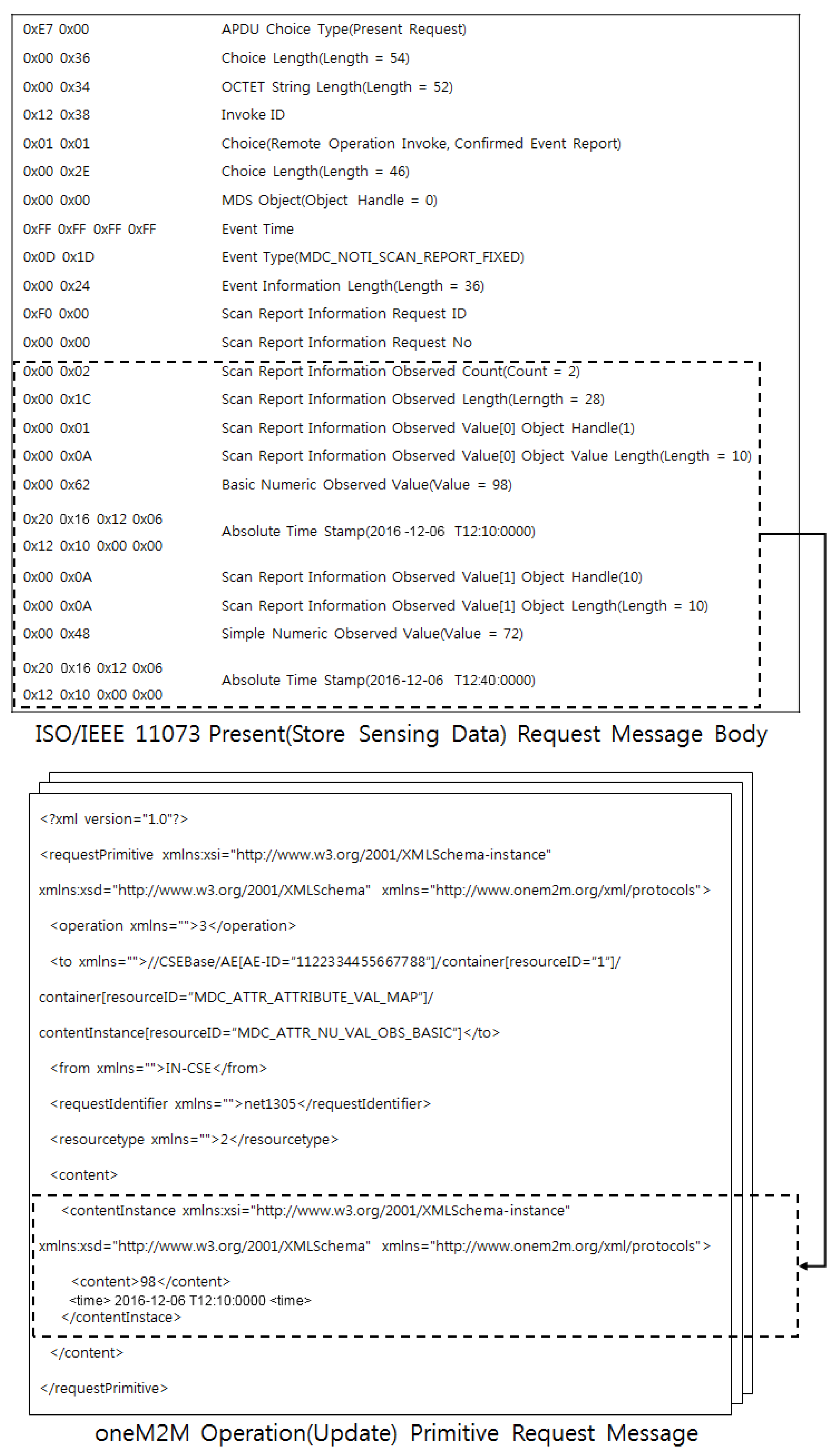
Biomedical data measured by a PHD can be delivered in an ISO/IEEE 11073 Present (Store Sensing Data) Request message. Because a single ISO/IEEE 11073 Present (Store Sensing Data) Request message can contain multiple biomedical data, more than oneM2M Update primitive Request messages can be built. Figure 11 shows how to convert an ISO/IEEE 11073 Present (Store Sensing Data) Request message into oneM2M Update primitive Request messages. For an ISO/IEEE 11073 Present (Store Sensing Data) Request message received, the gateway or the IoT server stores the measured biomedical information contained in (“Observed Value”, “Absolute Time Stamp”) fields into the appropriate places in its resource tree designated by “URL&Value”. Figure 12 shows an example of the process described in Figure 11. In the upper image of Figure 12, “APDU Choice Type” on the first line and “Event Type” on the ninth line indicate that this message is an ISO/IEEE 11073 Present Request message and a Store Sensing Data message, respectively. Two measured (observed) values are delivered in the dotted box of the upper figure: 90 is measured at time 6 December 2016, T12:10:0000 and 72 at time 6 December 2016, T12:40:0000. These values and measured times are transmitted in two oneM2M Update primitive Request messages to update the resource tree. Only one oneM2M Update primitive Request message is shown in the dotted box (No. 1) of the lower figure.
6. Buddy-ACK Authentication Scheme
Because the biomedical data obtained by a PHD may be very sensitive in terms of a patient’s privacy, the data need to be handled in a manner that prevents its exposure to unauthorized persons. In this study, two security schemes are proposed. First, a patient’s biomedical data obtained by a PHD are not stored as a single unit, but are stored in parts in the IoT server. The data are partitioned into several parts (two parts in this study) and stored separately in the IoT server. Bytes of the data are stored alternatively into two different locations. Furthermore, the separation information including the locations of the parts is not stored in the IoT server, but in the IoT authentication server. This means that anyone who wants to access the data will need to access both the IoT server and the IoT authentication server simultaneously.
Second, an authentication scheme called the Buddy-ACK authorization scheme is proposed in this study. In a normal authorization scheme, only a user needs to be authorized [32]. However, in the Buddy-ACK authorization scheme, specific biomedical data can be accessed only after both a patient and the related medical staff are authorized. We call the patient and the related medical staff “buddies”. Biomedical data can be accessed only after the acknowledgement (or consent) of the related buddy is obtained. In this way, the Buddy-ACK authorization scheme is stricter than normal authorization processes. As far as message authentication is concerned, existing encryption/digital signature schemes can be used [32]; this is not an issue we will discuss further.
The security schemes proposed in this study has the following properties:
- The separation storage of biomedical data: A patient’s biomedical data obtained by a PHD are not stored as a single unit, but are stored in parts on the IoT server. The data are partitioned into two parts, each having alternate bytes, and stored separately into the IoT server. The separation information including the locations of the parts is not stored in the IoT server but in the IoT authentication server. Because the IoT authentication server does not have data itself, an attacker would need to successfully breach both servers simultaneously. Even a system administrator of the IoT server cannot obtain the data because the IoT server does not have the separation information that describes where the data parts are located. When data are requested, the IoT server has to request the IoT authentication server for the locations of all the data parts to assemble all of the data parts for complete data.
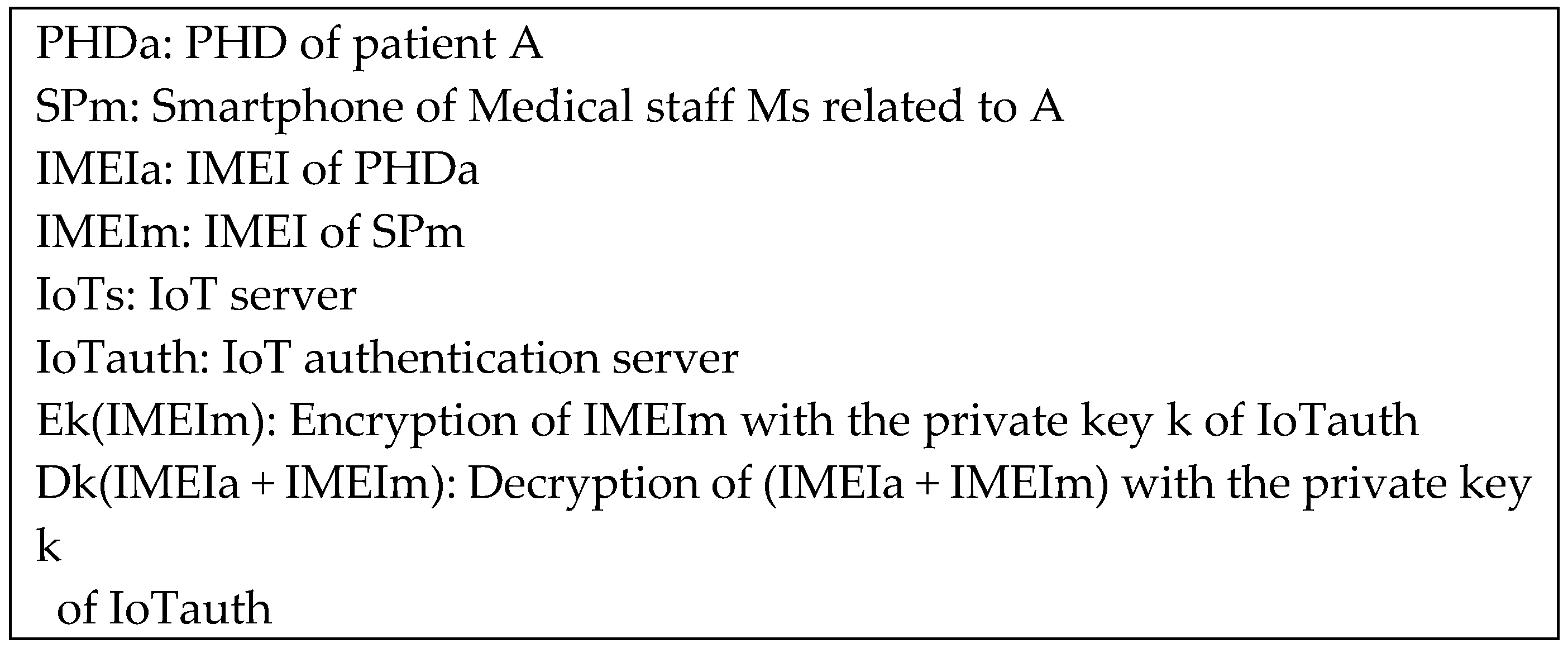
- The buddy-ACK authentication scheme: For the sake of patient privacy, the buddy-ACK authentication scheme is proposed in this study. A patient and the medical staff responsible for the patient are considered to be “buddies”. When a medical staff requests a patient’s data, acknowledgement (or consent) of the patient is needed. The IoT authentication server sends the separation information of the data only after the server receives the acknowledgement of the patient. Similarly, even when a patient requests his own data, acknowledgement of the related medical staff must be obtained. The acknowledgement is realized as encrypted IMEI (International Mobile Equipment of Identity) in this study. The encryption key is obtained when a patient (or a medical staff) registers at the IoT authentication server. Thus, the key is shared only by a patient (or a medical staff) and the IoT authentication server. In this way, an attacker may experience significant difficulties in accessing a patient’s data because the attacker must know the encryption keys of both the patient and the related medical staff to be successful.
Alarm signals that report the abnormal condition of the patient are exempt from the Buddy-ACK authorization process because the signals should be delivered to the related medical staff immediately. Push operations are used for the signals in the system.
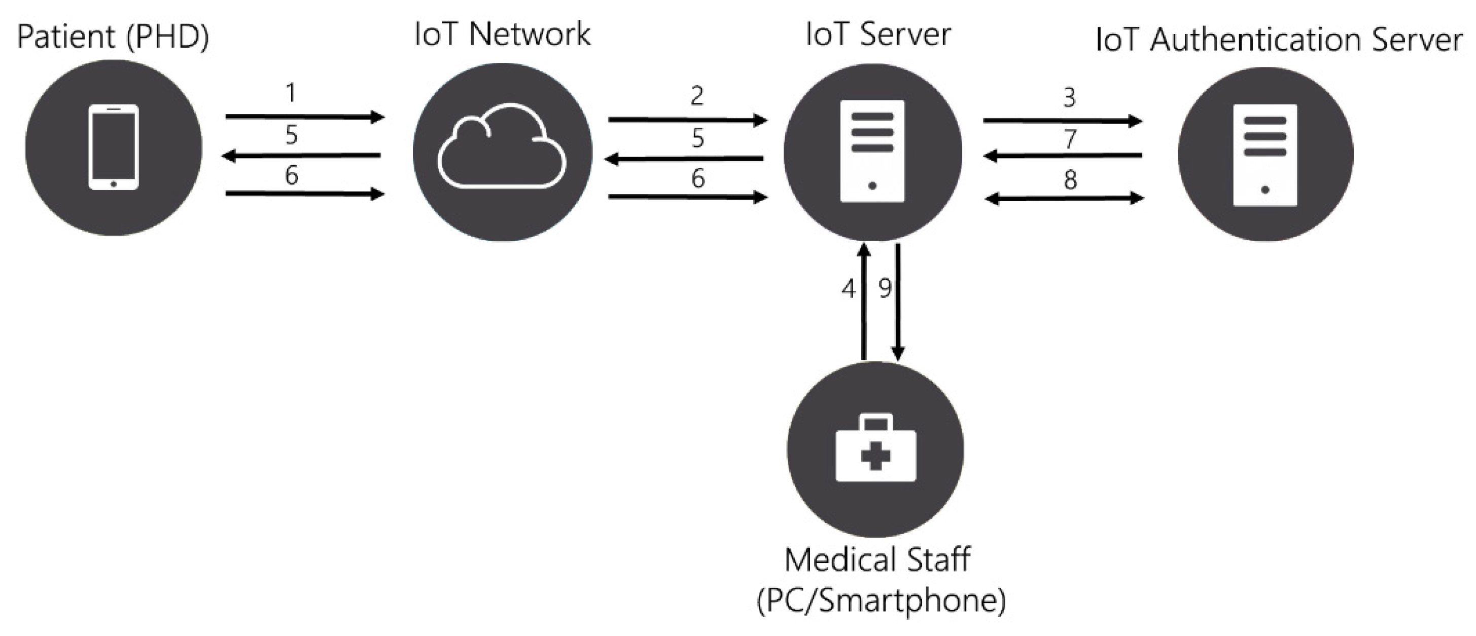
Figure 13 shows the Buddy-ACK authorization scheme process proposed in this study.
The Scheme 1 has the following sequences:
- (Storage sequence)
- PHDa sends measured biomedical data to IoTs through an IoT network.
- IoTs receives the data, and Splits the data into two parts to store separately
- IoTs sends the separation information (i.e., the locations of the two parts) to IoTauth and deletes the separation information from IoTs, and IoTauth stores the separation information received from IoTs
- (Retrieval sequence performed by Spm)
- Spm sends Ek(IMEIm) to IoTs to request A’s biomedical data
- IoTs requests ACK of PHDa to initiate the Buddy-ACK authorization process
- PHDa sends Ek(IMEIa) to IoTs as an ACK
- IoTs sends (Ek(IMEIm) + Ek(IMEIa)) to IoTauth
- IoTauth performs Dk(Ek(IDms) + Ek(IDa)) to determine whether it is the legitimate buddy, and IoTauth sends the related separation information to IoTs
- IoTs locates two parts of A’s biomedical data using the received separation information, and Assembles them to send to Ms
- (Retrieval sequence performed by PHDa)
Retrieval sequence performed by PHDa is very similar to Retrieval sequence performed by Spm, except that “Spm” and “Ek(IMEIm)” are replaced by “PHDa” and “Ek(IMEIa)”, respectively.
7. Experiments
The proposed IoT system for monitoring patients at home was constructed and evaluated through several experiments. The system was developed in C# under Windows 7 Operating System.
7.1. Experiment on the MQL Scheduling Algorithm
In the experiments to test the MQL scheduling algorithm, four types of PHDs were used to generate pulse oximetry data, ECG data, blood sugar data, and weight data. ECG data, the heaviest data of all, were obtained by gathering 300 data samples per second for 5 ms. Each result in the following graphs was obtained by averaging the results of ten experiments. The characteristics of four types of biomedical data used in these experiments are as follows:
- Pulse oximetry data: Message class (Urgent), Message priority (5.0), Messages size (64 bytes)
- ECG data: Message class (Urgent), Message priority (3.0), Messages size (1024 bytes)
- Blood sugar data: Message class (Non-urgent), Message priority (3.0), Messages size (64 bytes)
- Weight data: Message class (Non-urgent), Message priority (1.0), Messages size (64 bytes)
To compare the proposed MQL scheduling algorithm with other multiclass message scheduling algorithms, the MBDP algorithm was implemented. For the MBDP algorithm, the following maximum delay times were utilized: 0 second for urgent data, 50,000 seconds for blood sugar data, and infinity for weight data. Figure 14 shows the throughputs (the number of messages scheduled for transmission) generated by the MQL and the MBDP algorithms.
As seen in Figure 14, the MQL scheduling algorithm proposed in this study performs better than the MBDP scheduling algorithm. In addition, we found that the throughputs of the MQL algorithm increase almost linearly as the measurement time increases, whereas the throughputs of the MBDP algorithm increase with decreases in the increasing ratio. This is partially because the MQL algorithm performs significantly better than the MBDP algorithm, especially when the number of messages waiting to be scheduled becomes quite large. As measurement time increases, the number of messages waiting to be scheduled also increases. Compared to the MQL algorithm, the MBDP algorithm incurs greater overhead when recalculating the RTTS of every message in the waiting queues, and when moving messages between queues upon recalculation.
7.2. Experiment on the Protocol Conversion Process
When a PHD wants to connect to the IoT server, the PHD sends the server an ISO/IEEE 11073 Association Request message for connection. A gateway, located between the PHD and the server, needs to perform the protocol conversion process mentioned in Section 5, because the server does not support the ISO/IEEE 11073 protocol. Figure 15 and Figure 16 show screen captures of the results of the protocol conversion execution for connection establishment. The upper screen in Figure 15 shows the content of the ISO/IEEE 11073 Association Request/Response message, while the lower screen shows that of the oneM2M Operation (Retrieve) primitive Request/Response message. An explanation on the figures is omitted because the same example was explained in detail in Figure 6. The content of the oneM2M message is represented in XML.
In the upper screen of Figure 16, “<responseStatusCode>” is 4004 (on the third line), which means the PHD which requests connection has not been registered in the IoT server. Therefore, the PHD sends the IoT server its configuration in an ISO/IEEE 11073 Present (Notice Configuration) Request message for its registration to the server, as shown in Figure 17.
When the registration process for the PHD finishes, the resource tree shown in Figure 18 is created by the IoT server (IN-CSE). “<AE>” tag node for the PHD is created in the resource tree. Measured biomedical values of three objects by the PHD can be stored in the resource tree later. “content = “Default”” means that the related measured value will be stored when a oneM2M Operation (Update) primitive Request message arrives later.
8. Conclusions
In this paper, a remote monitoring system for patients at home in IoT environments is proposed, constructed, and evaluated through several experiments. To prepare for the massive number of PHDs needed, the system was designed as multilayered. To use PHDs as objects in an IoT system based on the oneM2M protocol, a protocol conversion process between ISO/IEEE 11073 protocol and oneM2M protocol was proposed and implemented. In addition, a multiclass data communication scheme was proposed and implemented based on the urgency of delivery to medical staff. For the protection of a patient’s privacy, two security schemes are proposed in this study. First, a patient’s biomedical data obtained by a PHD are not stored as a single unit, but stored in parts in the IoT server. Furthermore, the separated information is stored in the IoT authentication server. In this way, an attacker would need to successfully breach both servers simultaneously to access the data. Second, an authentication scheme called the Buddy-ACK authorization scheme is proposed in this study. In the Buddy-ACK authorization scheme, a specific piece of biomedical data can be accessed only after both a patient and the related medical staff are authorized.
The experiments on the constructed system showed that the system worked well; the protocol conversion process worked efficiently for IoT environments. The experiments also showed the MQL scheduling algorithm proposed in this study transmits urgent messages immediately, and transmits non-urgent messages later, when they will not interfere with urgent message transmissions. In addition, the MQL scheduling algorithm performs better than the MBDP scheduling algorithm. We also found that the throughputs of the MQL algorithm increase almost linearly as the measurement time increases, whereas the throughputs of the MBDP algorithm increase with decreases in the increasing ratio. This is partially because the MQL algorithm performs significantly better than the MBDP algorithm, especially when the number of messages waiting to be scheduled becomes quite large. In addition, despite the heavy traffic, the alarm signals of the highest class were immediately pushed to medical staffs due to the data classification scheme.
Acknowledgments
This research was supported by the Basic Science Research Programs grant through the National Research Foundation of Korea (NRF), funded by the Ministry of Education, Science and Technology (No. NRF-2015R1D1A3A03019278).
Author Contributions
KeeHyun Park conceived the ideas proposed in this paper and designed the Buddy-ACK authentication scheme. Joonsuu Park designed the MQL algorithm and performed the related experiments. JongWhi Lee designed the protocol conversion process and performed the related experiments. Finally, KeeHyun Park wrote the paper.
Conflicts of Interest
The authors declare no conflict of interest.
References
- Chaouchi, H. The Internet of Things: Connecting Objects to the Web; Wiley: Hoboken, NJ, USA, 2013. [Google Scholar]
- Hoeller, J.; Tsiatsis, V.; Mulligan, C.; Karnouskos, S.; Avesand, S.; Boyle, D. From the Machine-to-Machine to the Internet of Things: Introduction to a New Age Intelligence; Elsevier: Amsterdam, The Netherlands, 2014. [Google Scholar]
- Kearns, W.D.; Nams, V.O.; Fozard, J.L. Tortuosity in Movement Paths Is Related to Cognitive Impairment Wireless Fractal Estimation in Assisted Living Facility Residents. Meth. Inf. Med. 2010, 49, 592–598. [Google Scholar] [CrossRef] [PubMed]
- Chen, H.; Kalish, M.C.; Pagán, J.A. Telehealth and Hospitalizations for Medicare Home Healthcare Patients. Am. J. Manag. Care 2011, 17, 224–230. [Google Scholar]
- Kearns, W.D.; Fozard, J.L.; Becker, M.; Jasiewicz, J.M.; Craighead, J.D.; Holtsclaw, L.; Dion, C. Path Tortuosity in Everyday Movements of Elderly Persons Increases Fall Prediction beyond Knowledge of Fall History, Medication Use, and Standardized Gait and Balance Assessments. J. Am. Med. Dir. Assoc. 2012, 13, 665.e7–665.e13. [Google Scholar] [CrossRef] [PubMed]
- Taylor, J.; Coates, E.; Brewster, L.; Mountain, G.; Wessels, B.; Hawley, M.S. Examining the use of telehealth in community nursing: Identifying the factors affecting frontline staff acceptance and telehealth adoption. J. Adv. Nurs. 2015, 71, 326–337. [Google Scholar] [CrossRef] [PubMed]
- Kang, Y.; McHugh, M.D.; Chittams, J.; Bowles, K.H. Utilizing Home Healthcare Electronic Health Records for Telehomecare Patients with Heart Failure: A Decision Tree Approach to Detect Associations with Rehospitalizations. CIN Comput. Inform. Nurs. 2016, 34, 175–182. [Google Scholar] [CrossRef] [PubMed]
- Jarrett, E.; Amy, P.; Tsien, S.S.; Neil, C.; Loretta, S.; Cindy, C.; Michele, M.; Beth, E.C. Remote Health Monitoring for Older Adults and Those with Heart Failure: Adherence and System Usability. Telemed. e-Health 2016, 2, 480–488. [Google Scholar]
- Liu, L.; Stroulia, E.; Nikolaidis, I.; Miguel-Cruz, A.; Rincon, A.R. Smart homes and home health monitoring technologies for older adults: A systematic review. Int. J. Med. Inform. 2016, 91, 44–59. [Google Scholar] [CrossRef] [PubMed]
- Institute of Electrical and Electronics Engineers. Standard for Medical device communication–Part 00000: Framework and overview. IEEE Std. 2008, 1073. Available online: https://standards.ieee.org/findstds/standard/1073-1996.html (accessed on 7 March 2017). [Google Scholar]
- Institute of Electrical and Electronics Engineers. Health informatics-Personal health device communication. IEEE Std. 2008, 11073–20601. Available online: https://standards.ieee.org/findstds/standard/11073-20601-2008.html (accessed on 3 March 2017). [Google Scholar]
- Pak, J.; Park, K. A smart personal activity monitoring system based on wireless device management methods. Commun. Comput. Inf. Sci. 2011, 184, 335–342. [Google Scholar]
- Pak, J.; Park, K. UbiMMS: An ubiquitous medication monitoring system based on remote device management methods. Healthc. Inf. Manag. J. 2012, 41, 26–30. [Google Scholar] [CrossRef]
- Pak, J.; Park, K. Advanced pulse oximetry system for remote monitoring and management. Biomed. Res. Int. 2002. [Google Scholar] [CrossRef] [PubMed]
- Park, K.; Lim, S. A multipurpose smart activity monitoring system for personalized health services. Inf. Sci. 2015, 314, 240–254. [Google Scholar] [CrossRef]
- oneM2M. Functional Architecture (TS-0001-V1.6.1). Available online: http://www.onem2m.org (accessed on 10 December 2015).
- oneM2M. Service Layer Core Protocol Specification (TS-0004-V1.0.1). Available online: http: www.inem2m.org (accessed on 10 December 2015).
- Grieco, L.A.; Alaya, M.; Montei, T.; Drira, K. Architecting information centric ETSI-M2M systems. In Proceedings of the 2014 IEEE International Conference on Pervasive Computing and Communications Workshops (PERCOM Workshops), Budapest, Hungary, 24–28 March 2014; pp. 211–214.
- Lam, S. Protocol Conversion. IEEE Trans. Softw. Eng. 1988, 14, 353–362. [Google Scholar] [CrossRef]
- Glombitza, N.; Mietz, R.; Römer, K.; Fischer, S.; Pfisterer, D. Self-Description and Protocol Conversion for a Web of Things. In Proceedings of the 2010 IEEE International Conference on Sensor Networks, Ubiquitous, and Trustworthy Computing (SUTC), Newport Beach, CA, USA, 7–9 June 2010; pp. 229–236.
- Delac, G.; Budiselic, I.; Zuzak, I.; Skuliber, I.; Stefanec, T. A Methodology for SIP and SOAP Integration Using Application-Specific Protocol Conversion. ACM Trans. Web 2012, 6, 1–28. [Google Scholar] [CrossRef]
- Suo, H.; Wan, J.; Zou, C.; Liu, J. Security in the internet of things: A review. In Proceedings of the 2012 International Conference on Computer Science and Electronics Engineering, ICCSEE 2012, Hangzhou, China, 23–25 March 2012; Volume 3, pp. 648–651.
- Hamdi, M.; Abie, H. Game-based adaptive security in the Internet of Things for eHealth. In Proceedings of the 2014 IEEE International Conference on Communications, ICC 2014, Sydney, Australia, 10–14 Junuary 2014; pp. 920–925.
- Arias, O.; Hoang, K. Privacy and Security in Internet of Things and Wearable Devices. IEEE Trans. Multi-Scale Comput. Syst. 2015, 1, 99–109. [Google Scholar] [CrossRef]
- Bhattacharyya, D.; Ranjan, R.; Alisherov, F.; Choi, M. Biometric Authentication: A Review. Int. J. Serv. Sci. Technol. 2009, 2, 13–28. [Google Scholar]
- Schlöglhofer, R.; Sametinger, J. Secure and usable authentication on mobile devices. In Proceedings of the 10th International Conference on Advances in Mobile Computing and Multimedia, New York, NY, USA, 3–5 December 2012; p. 257.
- Meng, W.; Wong, D.S.; Furnell, S.; Zhou, J. Surveying the development of biometric user authentication on mobile phones. In IEEE Communications Surveys and Tutorials; Institute of Electrical and Electronics Engineers Inc.: New York, NY, USA, 2015; Volume 17, Issue 3, pp. 1268–1293. [Google Scholar]
- Arteaga-Falconi, J.S.; Al Osman, H.; El Saddik, A. ECG Authentication for Mobile Devices. IEEE Trans. Instrum. Meas. 2016, 65, 591–600. [Google Scholar] [CrossRef]
- Sadiq, B.; Madan, R.; Sampath, A. Downlink scheduling for multiclass traffic in LTE. EURASIP J. Wired. Commun. Netw. 2009, 2009, 510617. [Google Scholar] [CrossRef]
- Giluka, M.K.; Rajoria, N.; Kulkarni, A.C.; Sathya, V.; Tamma, B.R. Class based dynamic priority scheduling for uplink to support M2M communications in LTE. In Proceedings of the 2014 IEEE World Forum on Internet of Things, Seoul, Korea, 6–8 March 2014; pp. 313–317.
- Watkins, C.; Dayan, P. Q-learning. Mach. Learn. 1992, 8, 279–292. [Google Scholar] [CrossRef]
- Stallings, W. Crptography and Network Security: Principles and Practices, 6th ed.; Prentice Hall: Upper Saddle River, NJ, USA, 2014. [Google Scholar]
Figure 1.
Structure of the IoT (Internet of Things) system for monitoring patients at home.
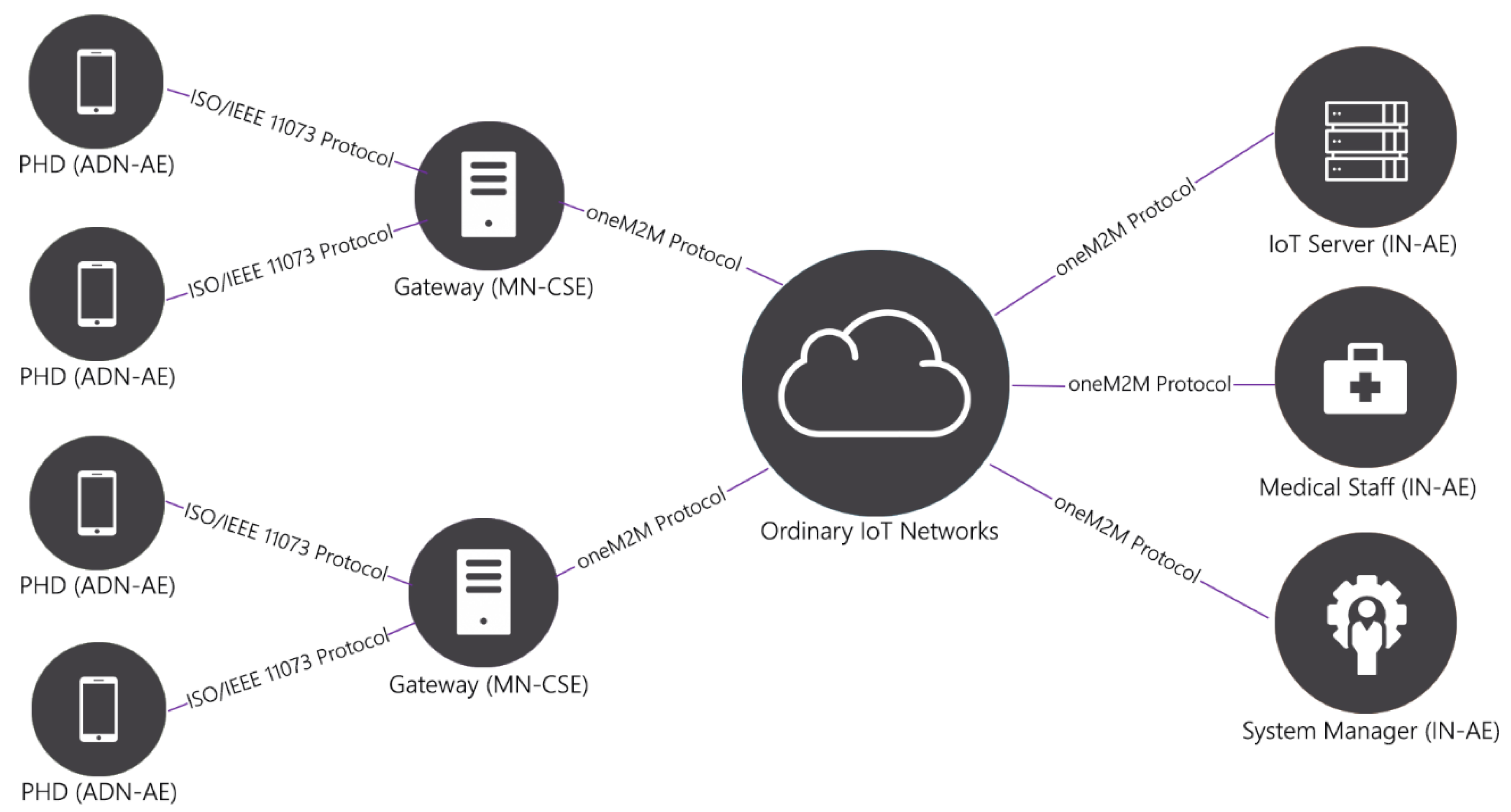
Figure 2.
Internal structure of the oneM2M (Machine-to-Machine) IoT system.
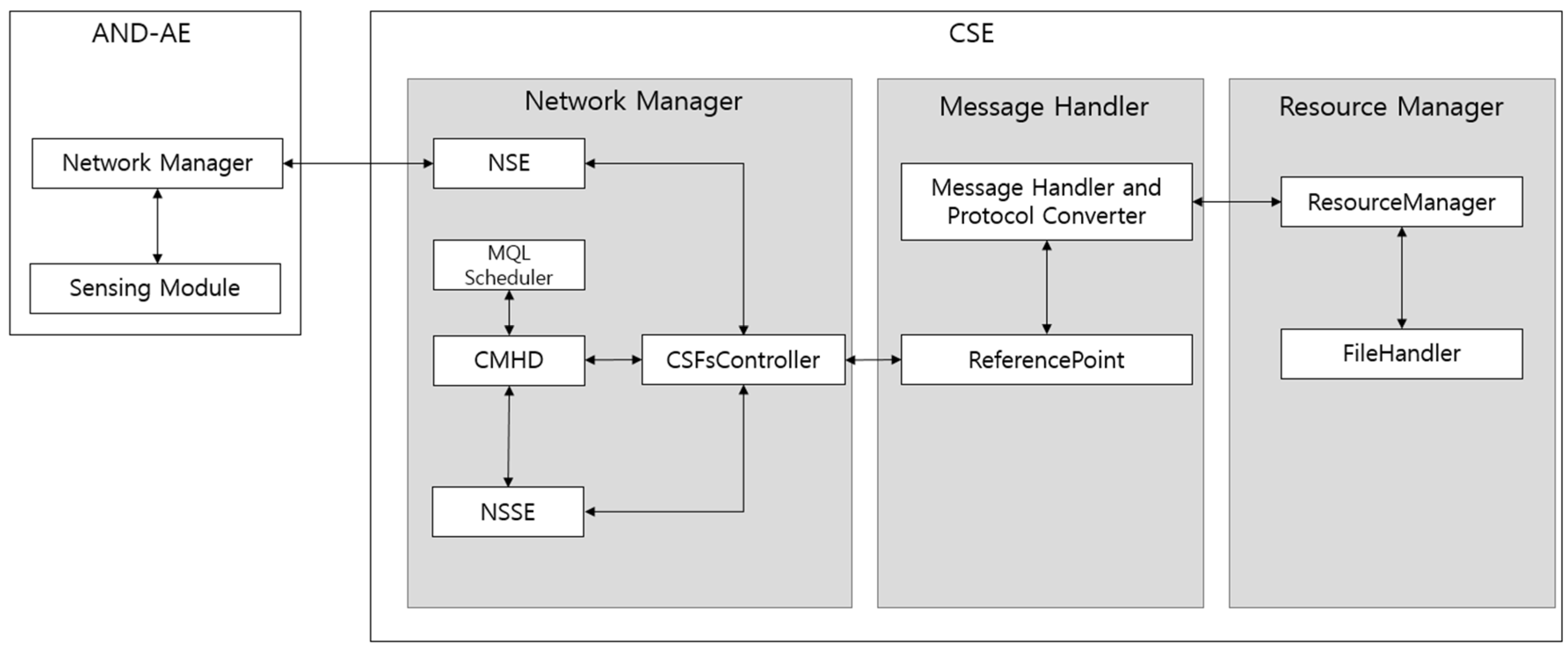
Figure 3.
Q-learning algorithm.

Figure 4.
Program modules for the protocol conversion process.
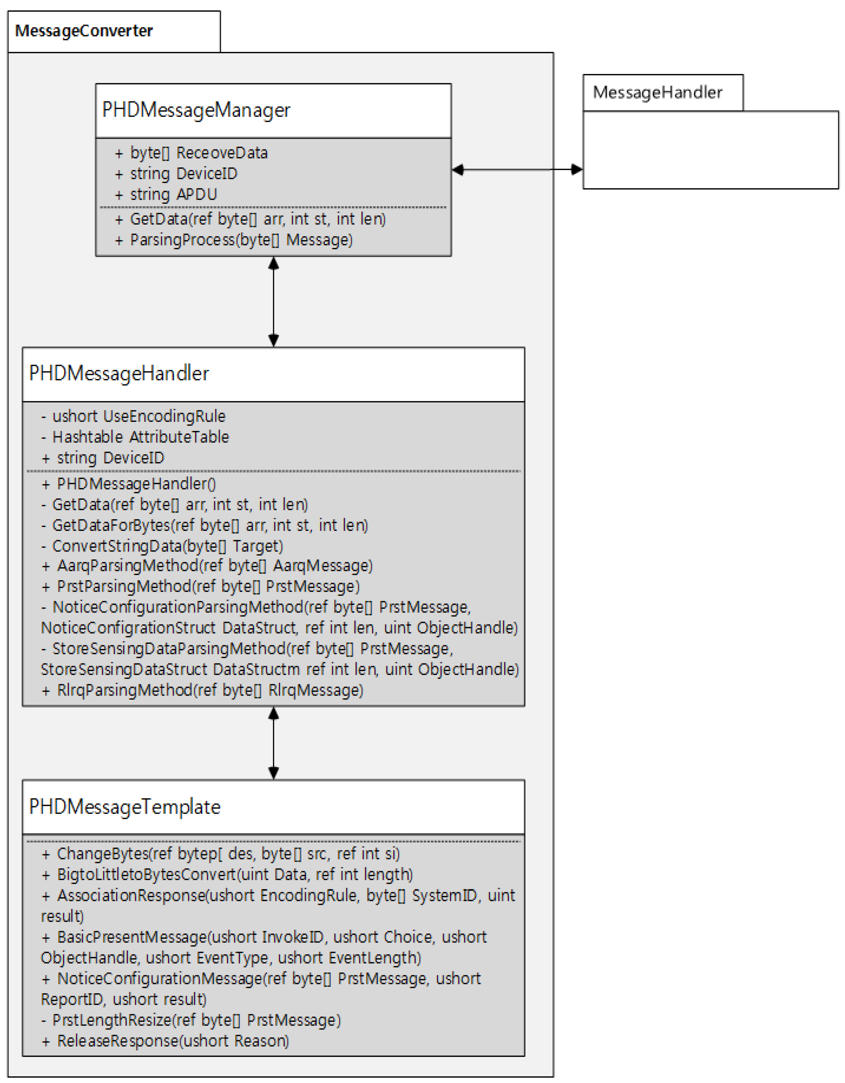
Figure 5.
Conversion of an ISO/IEEE 11073 Association Request message to a oneM2M Retrieve primitive Request message.
Figure 5.
Conversion of an ISO/IEEE 11073 Association Request message to a oneM2M Retrieve primitive Request message.

Figure 6.
An example of the process described in Figure 5.
Figure 6.
An example of the process described in Figure 5.

Figure 7.
Conversion of a oneM2M Retrieve primitive Response message to an ISO/IEEE 11073 Association Response message.
Figure 7.
Conversion of a oneM2M Retrieve primitive Response message to an ISO/IEEE 11073 Association Response message.

Figure 8.
Conversion of an ISO/IEEE 11073 Present (Notice Configuration) Request message to oneM2M Create primitive Request messages.
Figure 8.
Conversion of an ISO/IEEE 11073 Present (Notice Configuration) Request message to oneM2M Create primitive Request messages.
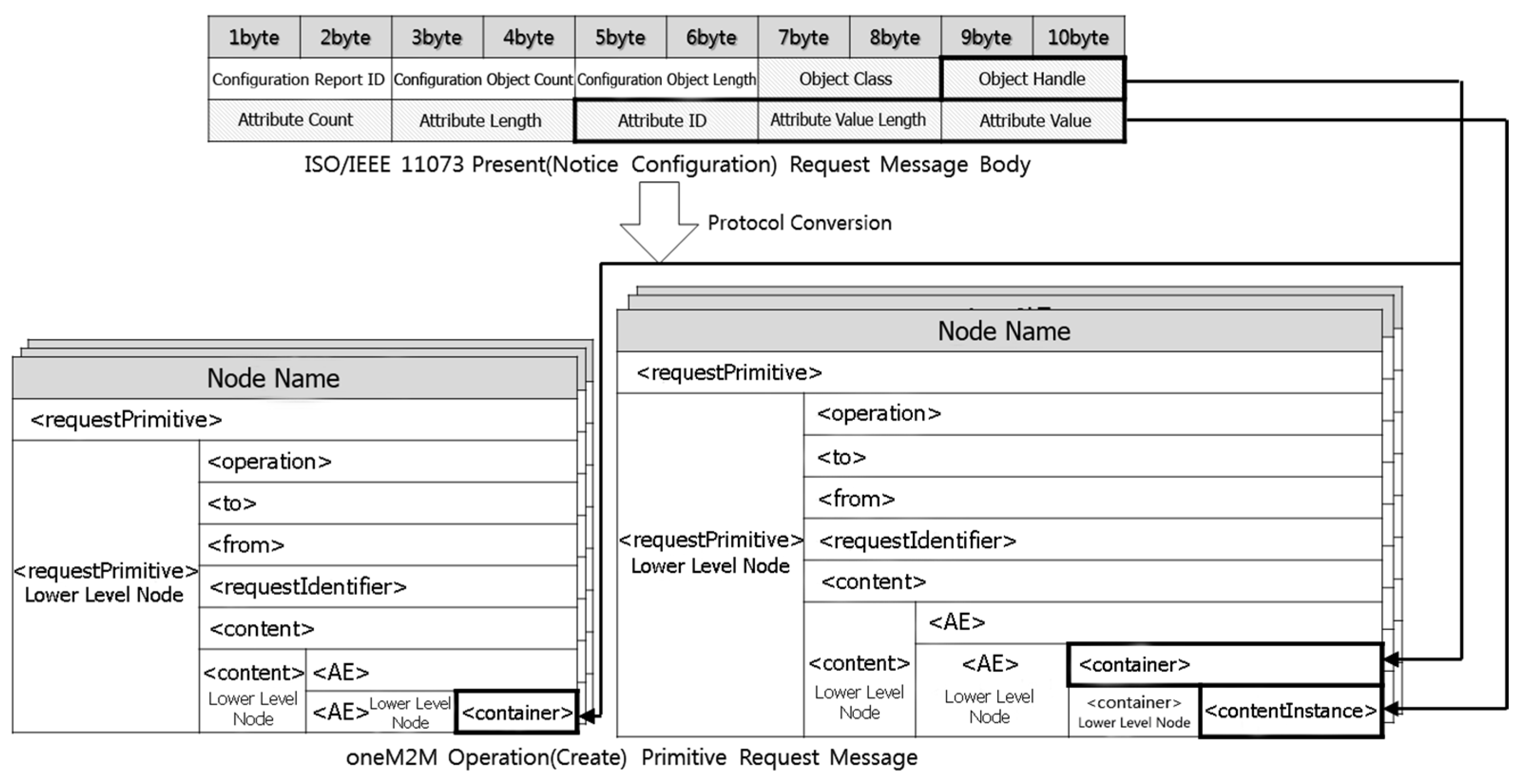
Figure 9.
An example of the process described in Figure 8 (ISO/IEEE 11073 Present (Notice Configuration) Request message).
Figure 9.
An example of the process described in Figure 8 (ISO/IEEE 11073 Present (Notice Configuration) Request message).
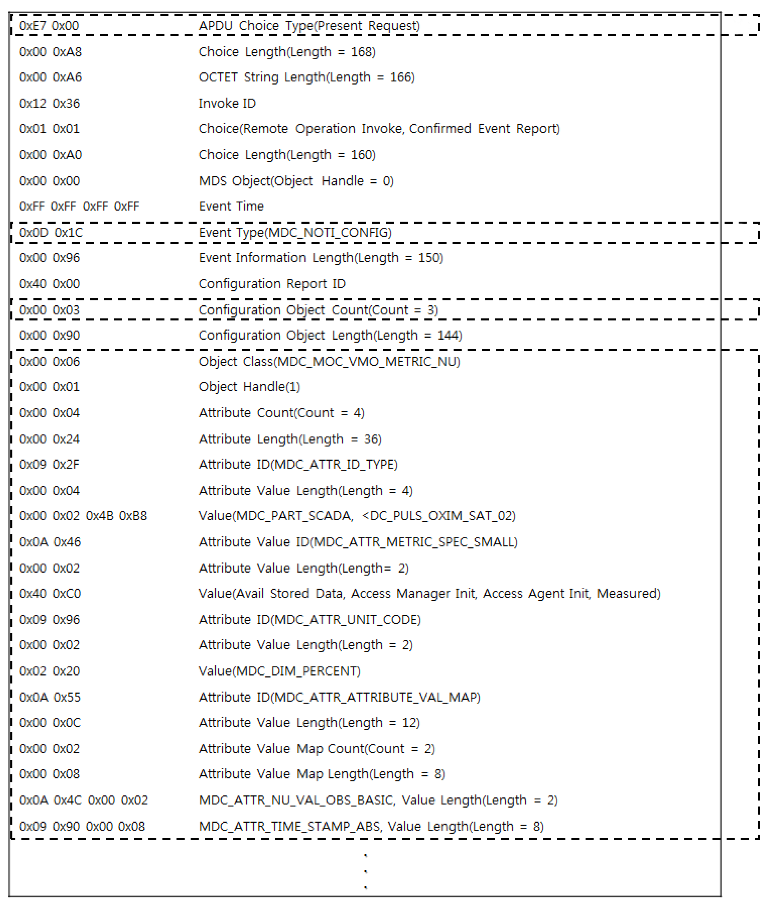
Figure 10.
An example of the process described in Figure 8 (oneM2M Create primitive Request message).
Figure 10.
An example of the process described in Figure 8 (oneM2M Create primitive Request message).
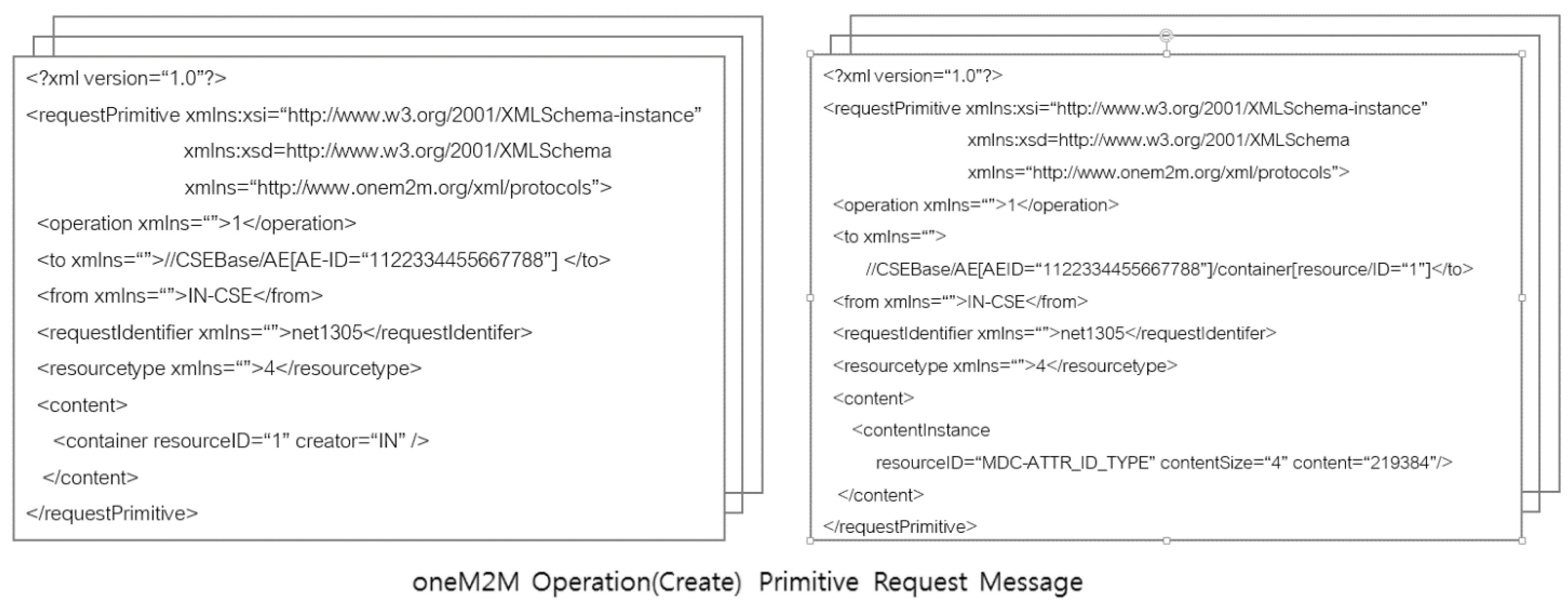
Figure 11.
Conversion of an ISO/IEEE 11073 Present (Store Sensing Data) Request message to oneM2M Update primitive Request messages.
Figure 11.
Conversion of an ISO/IEEE 11073 Present (Store Sensing Data) Request message to oneM2M Update primitive Request messages.
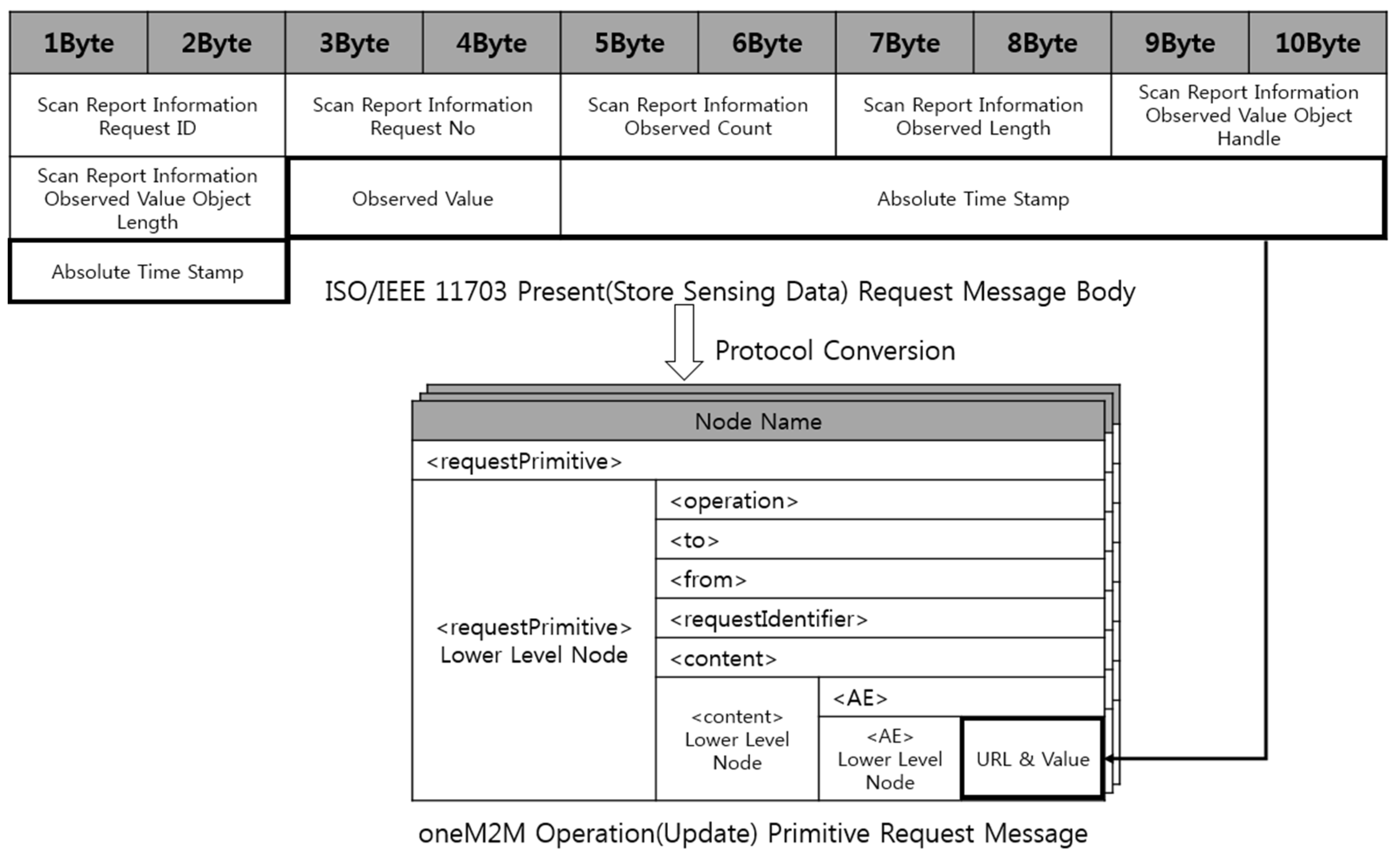
Figure 12.
An example of the process described in Figure 11.
Figure 12.
An example of the process described in Figure 11.

Figure 13.
Buddy-ACK authorization scheme process.

Scheme 1.
Buddy-ACK authorization scheme.

Figure 14.
Throughputs of the MQL (Multiclass Q-learning) and the MBDP (Multiclass Based Dynamic Priority) scheduling algorithms.
Figure 14.
Throughputs of the MQL (Multiclass Q-learning) and the MBDP (Multiclass Based Dynamic Priority) scheduling algorithms.

Figure 15.
Screen captures of connection establishment (Conversion of an ISO/IEEE 11073 Association Request message into a oneM2M Retrieve primitive Request message).
Figure 15.
Screen captures of connection establishment (Conversion of an ISO/IEEE 11073 Association Request message into a oneM2M Retrieve primitive Request message).

Figure 16.
Screen captures of connection establishment (Conversion of a oneM2M Retrieve primitive Response message into an ISO/IEEE 11073 Association Response message).
Figure 16.
Screen captures of connection establishment (Conversion of a oneM2M Retrieve primitive Response message into an ISO/IEEE 11073 Association Response message).
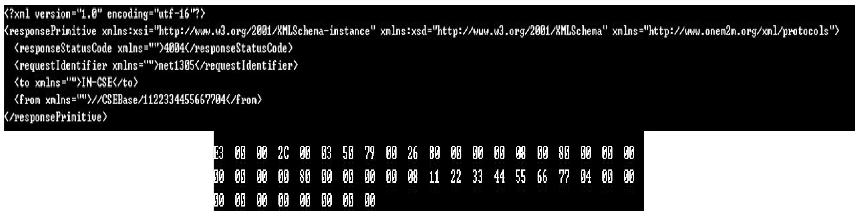
Figure 17.
Screen captures of registration (Conversion of an ISO/IEEE 11073 Present (Notice Configuration) Request message into a oneM2M Create primitive Request message).
Figure 17.
Screen captures of registration (Conversion of an ISO/IEEE 11073 Present (Notice Configuration) Request message into a oneM2M Create primitive Request message).
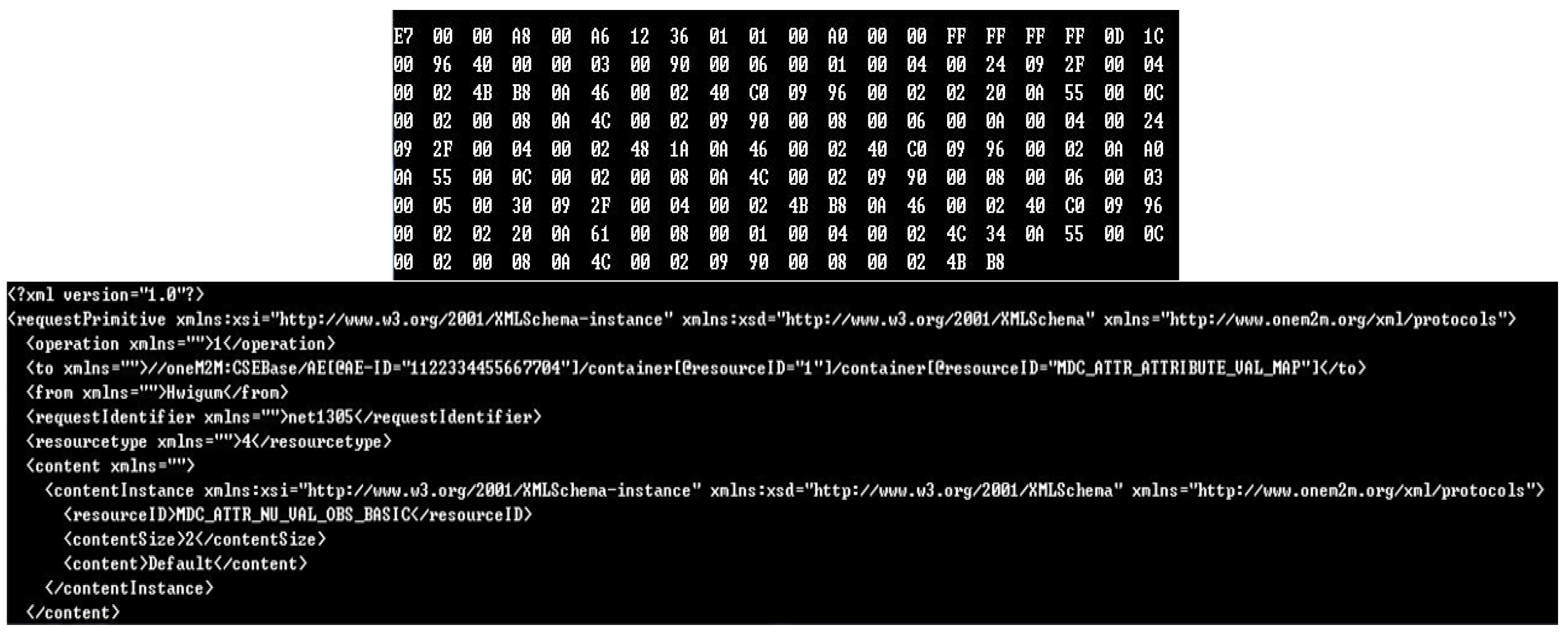
Figure 18.
Resource tree created by the IoT server (IN-CSE) after the registration process.
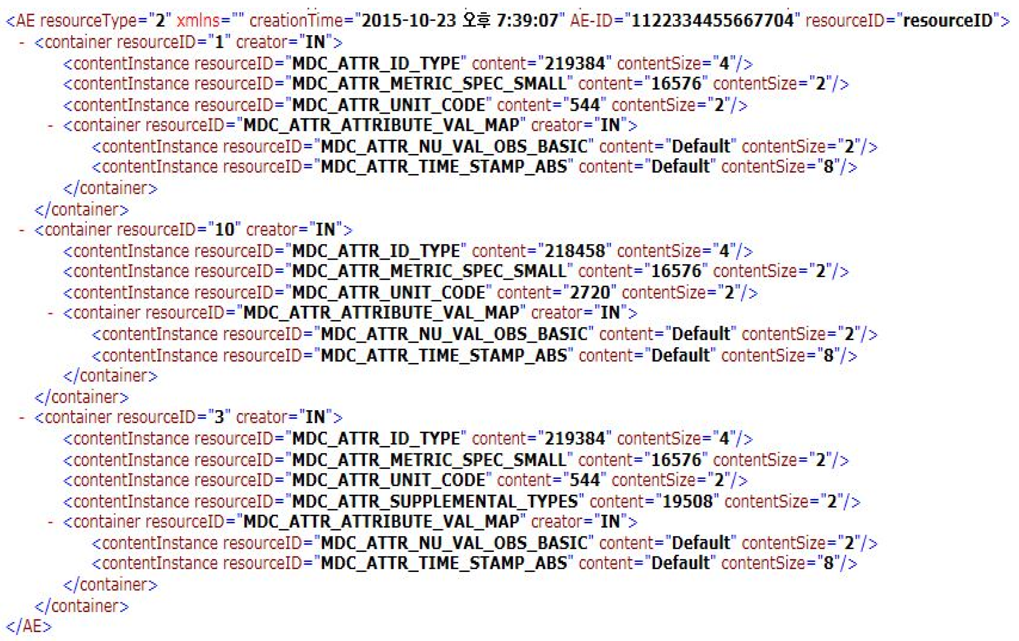
Figure 19.
Captured screens of registration (Conversion of an ISO/IEEE 11073 Present (Store Sensing Data) Request message into a oneM2M Update primitive Request message).
Figure 19.
Captured screens of registration (Conversion of an ISO/IEEE 11073 Present (Store Sensing Data) Request message into a oneM2M Update primitive Request message).

| oneM2M Primitive Request Message | HTTP Message |
|---|---|
| Operation | Method in Header |
| To | Request-Target in Header |
| ResourceType | Content-Type in Header |
| RequestID | X-M2M-RI in Header |
| Content | Body |
| oneM2M Primitive Response Message | HTTP Message |
|---|---|
| responseCode | Status Code |
| RequestID | X-M2M-RI in Header |
| Content | Body |
| QTable | 1 | 2 | 3 | 4 | 5 | 6 | 7 | 8 | 9 | 10 |
| 1 | ||||||||||
| … | ||||||||||
| 5 | 5.11 | 0.23 | 4.67 | 9.06 | 9.26 | 6.25 | 2.50 | 2.32 | 9.46 | 6.86 |
| … | ||||||||||
| 10 | ||||||||||
| Message Queues | Events | 1 | 2 | 3 | … | |||||
| UrgentQ | … | M17/5.0 | M01/4.9 | M02/3.81 | … | |||||
| NonUrgentQ[1] | … | … | … | … | … | |||||
| … | … | … | … | … | … | |||||
| NonUrgentQ[9] | Before the arrival of M18 | M09/2.0 | … | … | ||||||
| After the arrival of M18 | M18/3.0 | M09/2.9 | … | |||||||
| ISO/IEEE 11073 Protocol Request message | oneM2M Protocol Request message |
| Association Request message | Retrieve primitive Request message |
| Present (Notice Configuration) Request message | Create primitive Request message(s) |
| Present (Store Sensing Data) Request message | Retrieve primitive Request message(s) |
| Update primitive Request message(s) | |
| Association Release Request message | - |
| - | Delete primitive Request message |
© 2017 by the authors. Licensee MDPI, Basel, Switzerland. This article is an open access article distributed under the terms and conditions of the Creative Commons Attribution (CC BY) license ( http://creativecommons.org/licenses/by/4.0/).
Share and Cite
MDPI and ACS Style
Park, K.; Park, J.; Lee, J. An IoT System for Remote Monitoring of Patients at Home. Appl. Sci. 2017, 7, 260. https://doi.org/10.3390/app7030260
AMA Style
Park K, Park J, Lee J. An IoT System for Remote Monitoring of Patients at Home. Applied Sciences. 2017; 7(3):260. https://doi.org/10.3390/app7030260
Chicago/Turabian StylePark, KeeHyun, Joonsuu Park, and JongWhi Lee. 2017. "An IoT System for Remote Monitoring of Patients at Home" Applied Sciences 7, no. 3: 260. https://doi.org/10.3390/app7030260
Note that from the first issue of 2016, this journal uses article numbers instead of page numbers. See further details here.