A Novel Dual–Parallelogram Passive Rocking Vibration Isolator: A Theoretical Investigation and Experiment

1
State Key Laboratory of Robotics and System (HIT), Harbin 150001, China
2
School of Mechanical Engineering and Automation, Harbin Institute of Technology Shenzhen Graduate School, Shenzhen 518055, China
3
Shenzhen Institutes of Advanced Technology, Chinese Academy of Sciences, Shenzhen 518055, China
*
Authors to whom correspondence should be addressed.
Appl. Sci. 2017, 7(4), 367; https://doi.org/10.3390/app7040367
Submission received: 3 March 2017
/
Revised: 4 April 2017
/
Accepted: 4 April 2017
/
Published: 7 April 2017
(This article belongs to the Section Energy Science and Technology)
Abstract
:Vibration isolators with quasi-zero stiffness (QZS) perform well for low- or ultra-low-frequency vibration isolation. This paper proposes a novel dual-parallelogram passive rocking vibration isolator with QZS that could effectively attenuate in-plane disturbances with low-frequency vibration. First, a kinematic model of the proposed vibration isolator was established and four linear spring configuration schemes were developed to implement the QZS. Next, an optimal scheme with good high-static-low-dynamic stiffness (HSLDS) performance was obtained through comparison and analysis, and used as a focus for the QZS model. Subsequently, a dynamic model-based Lagrangian equation that considered the spring stiffness and damping and the influence of the payload gravity center on the vibration isolation system was developed, and an average approach was used to analyze the vibration transmissibility. Finally, the prototype and test system were constructed. A comparison of the simulation and experimental results showed that this novel passive rocking vibration isolator could bolster a heavy payload. Experimentally, the vibration amplitude decreased by 53% and 86% under harmonic disturbances of 0.08 Hz and 0.35 Hz, respectively, suggesting the great practical applicability of this presented vibration isolator.
1. Introduction
Low and ultra-low-frequency vibration isolation systems are widely used to attenuate disturbances that affect device accuracy in the fields of precision/ultra-precision apparatus, navigation, and aerospace, among others. In general, a passive linear isolator can reduce vibration when the excitation frequency exceeds times the natural frequency of the isolation system, and the smaller stiffness the better isolation performance, but the weaker to anti-disturbance [1]. To achieve better vibration isolation, the effective isolation bandwidth can be enlarged using a relatively low stiffness system at the equilibrium position, or quasi-zero stiffness (QZS). Theoretically, all vibrations could be eliminated at a system stiffness of zero. However, such a system would readily cause relatively large system deflections and potential instability. To address this issue, non-linear, high-static-low-dynamic stiffness (HSLDS) springs could be used to achieve a stiffness of nearly zero and better vibration isolation effects. Furthermore, the simultaneous increase in system stiffness with increased deflection could help the system to quickly recover an equilibrium position, effectively enhancing the system’s capacities for vibration isolation and stability.
Non-linear passive vibration isolation has been intensively investigated [2]. Typical QZS isolation systems include the following: parallel positive and negative stiffness, non-linear Euler spring deflection, and single-pendulum principle-based isolations. The latter includes the use of folded, inverted, and conical pendulums to achieve high-static-low-dynamic QZS isolation. Additional options for isolation include a friction-rolling pendulum and viscoelastic materials.
To briefly review this topic, Carrella et al. initially proposed the concept of a QZS isolator and analyzed the dynamic characteristics [3,4,5]. Subsequent research on QZS isolation systems developed rapidly following the demonstration of QZS isolator actualization using parallel positive and negative stiffness. Under low-frequency harmonic excitation, a QZS vibration isolation seat comprising vertical positive and negative stiffness linear helical springs was found to reduce the root mean square of deviation to 67.2% [6]. An experiment was designed in which the load was fixed at the middle of the two vertical springs, and adjacent magnets with like poles were arranged on both sides of the springs to form a HSLDS unit. Ahn proposed an integrated design approach of a QZS mechanism [7]. This unit exhibited better performance in response to a small vibration disturbance compared with a unit comprising linear springs [8]. The law of magnets, in which like poles repel and unlike poles attract, can be used to explain the similarities of like poles with a negative spring and of unlike poles with a positive spring. Negative and positive springs with rubber ligaments, among other elements, comprise the QZS isolation system. An experimental analysis of this model demonstrated the validity of the system [9,10]. The characterization of a QZS isolation system composed of a Euler buckled beam as the negative stiffness corrector and a positive stiffness spring was analogous to the characterization of a soft spring [11]. Compared with a linear spring, the QZS isolation system performed better at a low frequency, with a decreased carrying capacity [12]. An experimental analysis of a QZS isolator composed of a cam-roller-spring as the negative stiffness corrector and a positive linear spring demonstrated an excellent capacity regarding either transmissibility or the initial isolation frequency, despite discontinuity of stiffness across the entire bandwidth [13]. In addition, the characteristic critical stability of the Euler column led to an ideal low-frequency vertical vibration isolation performance while experiencing elastic buckling under interference from mass load-induced pre-compression [14]. Moreover, according to the Euler bending beam principle, the Euler spring boundary condition was optimized to achieve QZS with a LaCoste spring linkage [15]. With structural improvement, the LaCoste spring linkage principle yielded excellent ultra-low frequency vibration isolation and allowed highly precise gravitational wave measurements [16]. A dual-chamber air spring, rubber membrane, and viscoelastic materials also played important roles in the field of low-frequency vibration isolation [17,18].
Single-pendulum principle-based vibration isolators always perform well at low frequencies. Folded pendulum isolators were first proposed, and here, a reasonable geometric arrangement and mass distribution could achieve an approximate central stiffness of zero [19]. Outstanding vibration isolation was observed at low frequencies because an isolator with a compliant structure (e.g., folded pendulum) could possess a large bandwidth, without influence from revolute joint friction [20]. An inverted pendulum has negative stiffness, and the presence of long rocking rods could decrease the natural frequency of a pendulum to 30 mHz. Attenuation could be as high as 65 dB under a disturbance frequency of 1 Hz [21]. A high-performance material and seismic attenuation system were designed to reduce the size of the inverted pendulum [22]. As Roberts linkage movement does not have a vertical component when the mechanism is displaced, the load exhibits QZS at the central position. The experiment demonstrated the strong effect of precision on vibration isolation, as well as the benefits of reasonably designed precision to ultra-low frequency vibration isolation [23]. For example, a long-period conical pendulum with Scott–Russel isolation has advantages such as a high loading capacity. Furthermore, vibration reduction could reach 75 dB within 0.5 Hz [24,25]. A friction rolling-pendulum is usually applied to the vibration isolation of a specific structure (e.g., earthquake isolator) [26]. Here, a ball, or rolling pendulum, moves on a selected three-dimensional (3D) rolling surface, the center of which changes as the curvature of the rolling surface transforms. When the load places positive pressure on the ball, friction can be ignored at the equilibrium position, where a QZS system is constituted. Experimentation revealed that the load could afford low-frequency disturbances from two directions.
Studies of QZS vibration isolation have focused on translational and vertical vibration. Regarding non-linear vibration isolation, harmonic response, jump phenomena, chaotic motion, resonance, and transmissibility have been deeply explored [27,28,29,30]. Recently, QZS vibration isolation has been introduced into the field of torsional vibration isolation through the constitution of a high-static-low-dynamic torsional stiffness unit. Xu et al. constructed a quasi-zero torsional stiffness mechanism by distributing four cylindrical cams symmetrically around a shaft [31]. Recently, Abbasi et al. proposed a HSLDS shaft and deeply studied the influence of stiffness and nonlinear damping on vibration isolation. The results proved the outstanding capability of this high-static-low-dynamic isolator [32]. However, reports of vibration isolation during rocking motions are rare, even though such low frequency vibrations are commonly encountered in situations such as sea waves and astronaut motion. Still, Xue optimized the parameters of a tuned liquid column damper to suppress pitching vibration [33], and Wei et al. focused on the influence of an anti-rolling tank on the rocking motions of ships, finding that the amplitude of rocking could be reduced by using optimized parameters [34].
This paper describes the design of a novel, dual-parallelogram, passive rocking vibration isolator with QZS for the attenuation of low-frequency vibration. The scheme of the vibration isolator is presented in Section 2, and the QZS of the mechanism and four different management approaches are described in Section 3. Section 4 presents the establishment of a dynamic model and an analysis of transmissibility. Section 5 demonstrates the capacity of this novel isolator, using simulation and experimental results. Finally, Section 6 presents the conclusions.
2. Kinematic Analysis of a Dual–Parallelogram Passive Rocking Vibration Isolator
2.1. Description of Mechanism
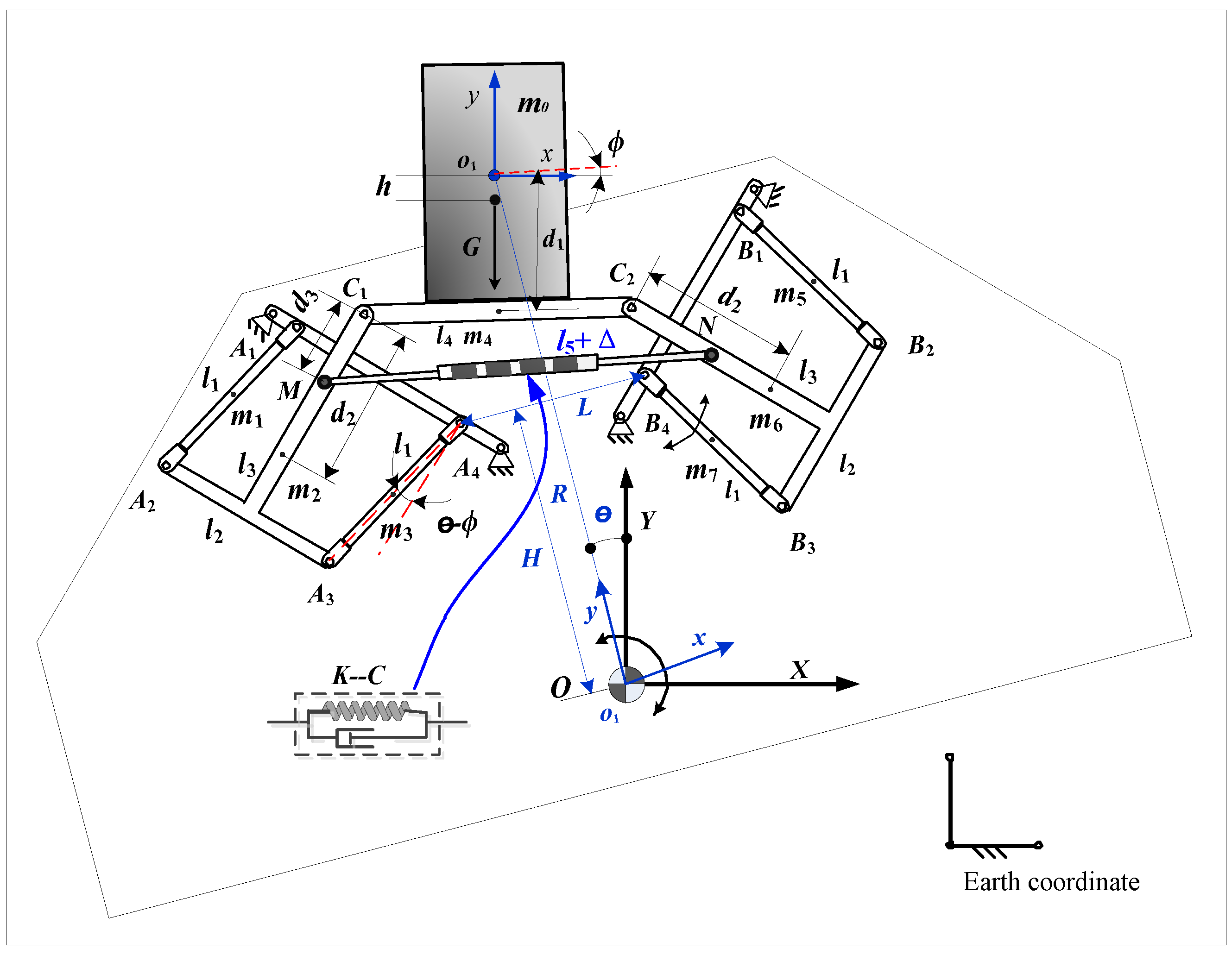
Figure 1 shows the mechanism of a dual-parallelogram passive rocking vibration isolator. In Figure 1, two rocking rods (A and B) in a pair of central symmetric parallelograms are fixed on the basic platform at an angle of 45 degrees to coordinate axis OX. One supporting rod is fixed on the rocking rod at one end of each parallelogram, and at the other end the supporting rod connects with the vibration isolation platform through revolute joint C. A spring-damper rod is arranged to connect the two supporting rods. At the initial position, the spring-damper rod is parallel to the vibration isolation platform, where load m is fixed.
The absolute coordinate system of the basic platform (i.e., where it rocks) is . is the dynamic coordinate system established at the rotating center of the load mass. When the basic platform is fixed, the rocking system holds one rotational degree of freedom around , and the internal rods of the system move as angular changes. The rocking rods, , are the rods in the parallelogram, the mass center of which hinges on the respective shape. To simplify the calculation, and have an integrated body that holds one associated center of mass. The length of the vibration isolation platform is . is the distance from to the vibration isolation platform, and is the initial length of the spring. At the initial position, no tension or pressure is exerted on the spring. is the distance from the ends of the spring-damper rods to points ( and ) on the ipsilateral vibration isolation platform. According to the geometric relationship, the relationship of rod lengths with position can be determined as:
where L refers to the distance from the double parallel quadrilateral mechanisms (DPQM) to the fixed points A4 and B4.
2.2. Kinematic Analysis
The kinematic relationship between the rods in a multiple-rod isolation mechanism is relatively complicated. The basic platform rocks around a turning center , with angular . Meanwhile, the vibration isolation platform exhibits coupled motion—translation and rotation around . is the angle between the local coordinate system and the absolute coordinate system . Figure 2 shows the kinematic positions of the rods.
The mass center (, , , , ) is the respective geometric center of each rod. is the distance from the mass center of each “T”-frame rod (, ) to and , respectively. The load and rod masses are . The mass center of each rod is defined as , i = 1, 2, …, 7. and are generalized coordinates. Symmetry yields the following kinematic relationship:
where , , , and
This kinematic relationship could be used to obtain the kinematic position of the center of mass and rotation angle of each rod. Table 1 shows the geometrical and mass parameters and moment of inertia.
3. QZS Analysis
QZS isolators perform excellently in the field of low-frequency vibration isolation, thus warranting research into their construction and distribution. Using a stiffness analysis, this section describes in detail the main parameters that directly influence QZS and the four linear spring configuration schemes used to build QZS systems.
3.1. Modeling of the QZS System
The stiffness of a vibration isolator system strongly influences its effectiveness, especially at low- or ultra-low-frequency vibrations. As a reasonably designed HSLDS isolator can reduce most vibrations, the torsion stiffness should be analyzed during the first stage.
Figure 2 demonstrates that two ends of the linear spring damper () connect with two “T”-frame rocking rods at points and . This spring is horizontal at the initial position, and the rod positions within the two parallelograms are symmetric. and represent the coordinates of , and represent the coordinates of . From the system structure, the following relationship can be obtained:
where is the linear spring stiffness and is the initial spring length. Assuming the length of the spring will change to under the action of a force, we can obtain:
where , .
When , the static system stiffness can be obtained using the virtual work principle. Assuming that load rotates around to an angular under external torque , the displacements of rods and elastic potential energy of the spring change simultaneously, and the influence of gravity of the lightweight spring damper on the system can be ignored. The energy caused by joint friction is also ignored in this paper. According to the virtual work principle, we can determine the following relationship:
where represent the displacement of each respective rod’s center of mass, .
According to the torsional motion, the equivalent torsion stiffness of the system can be expressed as:
Equations (5) and (6) are used to determine the equivalent stiffness. Torsional moment comprises two components: the torque exerted by the weight of the load and the isolator itself, and equivalent torque produced by the linear spring at . According to the mechanism kinematics, when is equal to zero, the relationship between the equivalent torque, equivalent torsional stiffness, and rotation angle can be depicted as follows.
Figure 3a demonstrates the strong non-linearity of the relationship between the equivalent torque and torsional angle at different gravity centers (). Note that h = −36.87 is a critical position where the equivalent torsion is approximately zero. In Figure 3b, the positions of the gravity and rotation centers of the load are clearly important. When h > −36.87, the equivalent torsional stiffness is negative, whereas when h < −36.87, the equivalent torsional stiffness is positive. Furthermore, when h = −36.87, the mechanism is at equilibrium, and the equivalent torsional stiffness is zero. The preceding results suggest that the load’s gravity center position strongly influences the equivalent torsional stiffness. Each equivalent non-linear torsional stiffness is associated with an independent linear spring stiffness, such that when the load is at equilibrium position (), is near zero. When QZS is implemented, stiffness increases the non-linearity associated with load movement. The spring stiffness , does not affect the load’s equilibrium position, but rather influences the non-linearity of the QZS isolator. Moreover, the transmissibility of non-linear stiffness is a key factor in vibration isolation.
The complexity of the previously derived stiffness model can be expected to present challenges in subsequent dynamics and transmissibility research. Note that the equivalent torsion and torsional stiffness are symmetric, and that at the zero point, the stiffness is also zero. For this study, an odd polynomial was used to develop a torsion-based stiffness model, as shown in Equation (7).
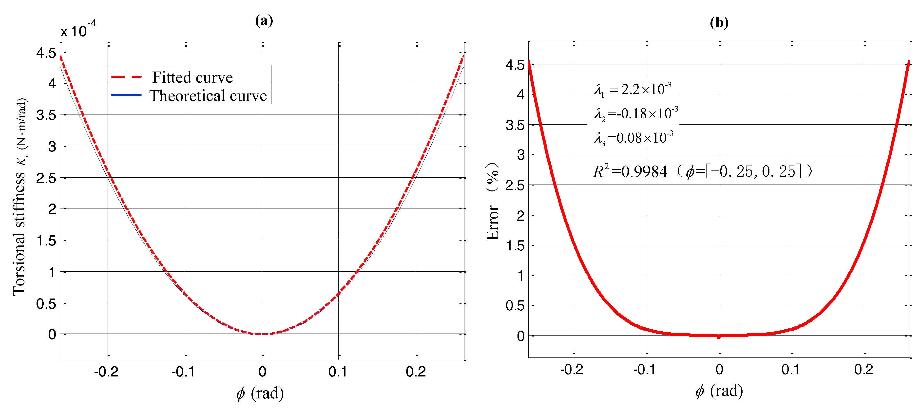
The equivalent torsional stiffness can be obtained from the first-order derivative of the equivalent torsion. The theoretical and fitted curves of the equivalent torsional stiffness and the error distribution curve at are given in Figure 4.
From the Figure 4, the simulation results indicate that the modeling error is within 5% in the rocking range of [−pi/12, pi/12]. Notably, this error is only 0.2% in the area of [−0.1, 0.1], and the goodness-of-fit scores , thus verifying the feasibility of this polynomial-based stiffness model.
3.2. Comparative Analysis of Four Linear Spring Configuration Schemes to Achieve QZS
The characteristic of QZS isolators suggests that the linear spring stiffness is zero at the equilibrium position. To meet the demand for vibration isolation at lower frequencies, a lower equivalent torsional stiffness distribution is needed. Accordingly, four configuration schemes, (a), (b), (c), and (d), are shown in Figure 5 (a–d, respectively). Here, the same stiffness coefficient and initial length () were adopted, and in Figure 5c, two springs with symmetric distribution are used. Equivalent torsional stiffness can be obtained using the method described in Section 3.1.
In Figure 5a, the spring chain is placed between two symmetric “T”-frame rocking rods, allowing changes in the equivalent torsional stiffness via changes in the stiffness coefficient of the linear spring and the distance variable, . In Figure 5b, the spring chain connects the adjacent sides of two parallelograms. would change as the spring length increased in response to an input disturbance. For schemes (a) and (b), if the same and values were used, scheme (a) would yield less equivalent torsional stiffness, which would be beneficial to ultra-low-frequency vibration isolation. The conformations of schemes (c) and (d) depend on the installation method. In Figure 5c, the linear spring is connected to the basic platform, yielding a symmetric distribution, whereas in Figure 5d, the linear spring is connected to one rod within the mechanism.
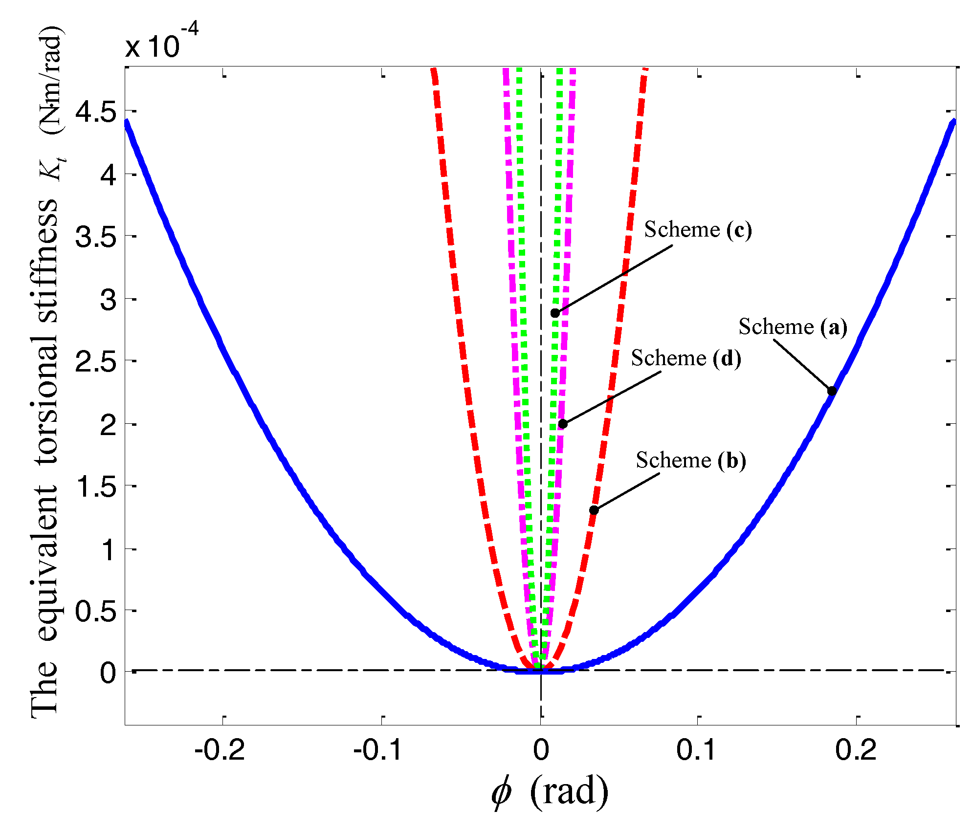
Figure 6 shows the distributions of equivalent torsional stiffness, corresponding to the four configuration schemes. Here, schemes (c) and (d) perform better when the initial length and stiffness coefficient are constant, and the rate of change in stiffness is primarily decided by and .
From the preceding analysis, scheme (a) yields a better high-static-low-dynamic performance and lower total stiffness than the other schemes, indicating the importance of spring stiffness distribution with regard to ultra-low-frequency vibration isolation. In addition, the linear spring chain configuration schemes should adhere to the principle of zero equivalent torsional stiffness at the equilibrium position, as well as of rod symmetry.
4. Dynamic Modeling of the Vibration Isolator
This section describes the deduction of a dynamic equation for the vibration isolator based on the Lagrangian equation. Here, damping of the rotation joint is analyzed as the difference in vibration isolation during translation and rotation. Subsequently, dynamic characteristics, including the amplitude–frequency characteristic and transmissibility, can be obtained using an average approach.
4.1. Dynamic Model Based on a Lagrangian Equation
Although the vibration isolator rotates, rods and in the parallelogram mechanism exhibit coupled translation and rotation motions. Therefore, a dynamic model can be derived using the motions of all rods, or simultaneous translation and rotation under the input disturbance. We established a dynamic model based on the Lagrangian equation, assuming that the input was harmonic excitation (), where and represent the amplitude and frequency, respectively. The displacement of the mass center of each rod is deduced in Section 2.2 (). Accordingly, the corresponding velocity of each can be described as:
Two independent variables and are chosen as generalized variables of the system, then the generalized velocity can be expressed as:
According to the Lagrangian equation:
where , is energy consumption, is external excitation.
The whole-system kinetic energy comprises both the translational and rotational kinetic energy of the rods. The total kinetic energy can be written as:
where is the translational velocity of the center of mass of each rod.
When and are equal to zero, the system is at the central position, and this static equilibrium position can be set as the overall system point with zero potential energy. represents the generalized coordinates of each rigid body. Therefore, the gravitational potential energy of the whole system can be expressed as:
Note that the initial spring length is l5. When the spring length is changed to l5′, the elastic energy Vk of the system is:
Energy is mainly lost because of damping of the spring and friction in the joint , which is proportional to the normal force and frictional coefficient. The symmetry of the system allows the grouping of pairs and consequent omission of the internal force. and can be described as
where is the normal force of each joint, is the rotational angular of each joint, and c is damping coefficient, and is friction factor, set to .
Furthermore, is the generalized velocity, and .
Based on Equations (11)–(14) and the Lagrange equation, we can obtain
where, is input disturbance torque . When the system is affected by sinusoidal disturbances, .
Normally, non-linear vibration isolation research involves analytical solutions to non-linear equations. However, we selected a numerical method to account for the large numbers of rods and relative complexity of our dynamic model.
4.2. Analysis of Transmissibility
Transmissibility is a key factor affecting the performance of a vibration isolator, and is normally represented by displacement at low-frequency vibrations. The transmissibility of the vibration isolator in this study was defined as the ratio of the vibration isolation platform output angle to the basic platform input angle. Although joint friction is dynamic and position-dependent, the rolling friction factor is relative small. Therefore, we could ignore the influence from Coulomb’s friction force and only consider viscous damping when solving transmissibility.
Note that when as shown in Figure 2, the structural symmetry along center o1 can be achieved, then we have , the system is in quasi zero stiffness state. Assuming the input harmonic excitation of the basic platform is due to the relationships between the motion state load, rods, and input disturbance torsion, the nonlinear dynamic differential equation of the whole isolator can be obtained as follows:
where , and are the moments of inertia, , , ; is the frequency of input disturbance; is the viscous damping coefficient; is the equivalent moment of inertia for all the rods with a torsion angle of .
Note that , assuming a relative angle of the basic and isolation platforms of , we obtain the angular velocity and angular acceleration. The differential equation for is written as:
where is the equivalent moment of inertia for all the rods about the torsion angle , .
This introduces a non-dimensional treatment of the system, and allows the vibration isolation equation to be obtained as follows:
where , , , , and .
We assume that , where is the function of , and the first- and second-order derivatives, respectively, are:
By substituting Equations (18) and (19) into Equation (17), we obtain the following:
where .
Based on the concept of the average method, wherein the average value is computed within a period, we obtain:
For simplicity, the response function of the amplitude and frequency is expressed as follows:
where .
Based on Equation (22), the system frequency ratio can be described as follows:
where , , and .
When , the system frequency ratio is expressed as follows:
Assuming that the amplitude of the real-time response is , .
where .
The characteristics of the vibration isolator are mainly influenced by parameters such as the stiffness coefficient, damping coefficient, and mass. Here, the basic system parameters were set at , , and . To demonstrate the advantages of this vibration isolation system, we set the amplitude to . Figure 7 depicts the relationship of transmissibility with the damping ratio.
As shown in Figure 7, both the up-jump frequency, Ωu, and down-jump frequency, Ωd, appear when Ω is <1. Regarding transmissibility, the nonlinear vibration isolation system has a greater capacity than the linear system. Furthermore, we can easily observe the strong influence of the damping ratio on the vibration isolation capacity. At an input excitation frequency lower than the up-jump frequency Ωu, the transmissibility decreases proportionally with the increase of damping ratio. In contrast, if the input excitation frequency exceeds the down-jump frequency Ωd, performance improves inversely with the increase of damping ratio. In addition, it can be seen from the figure that the damping rate has a great influence on the transmissibility in the resonance region, while it is less affected in the vibration isolation region. This phenomenon shows that the equivalent viscous damping has a great influence on the resonance region of the system. The damping is a highly-sensitive parameter that consumes much energy in the resonance region, so we can find in the figure that displacement transmissibility changes drastically with a slight change of the frequency ratio, and the dynamic characteristics exhibit good properties. Therefore, the performance of the nonlinear vibration isolation system is not only related to the damping ratio, but also to the input excitation amplitude. Figure 8 demonstrates the responses under different input disturbance amplitudes at a set k value of 200 N/m and nearly identical maximum transmissibility.
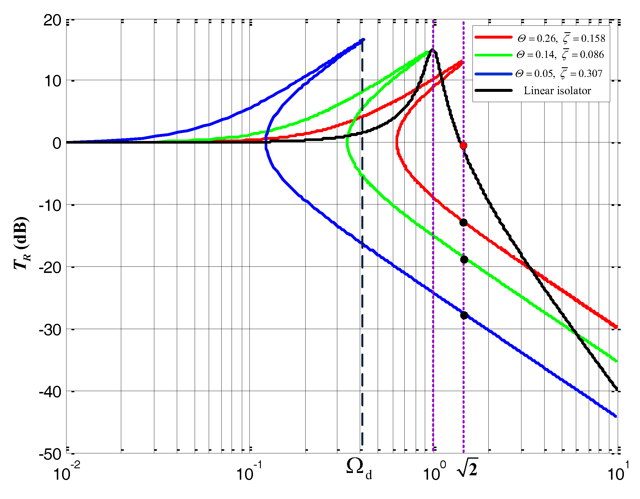
Figure 8 demonstrates that transmissibility is affected by the input harmonic disturbance amplitude, such that a higher input amplitude is associated with a higher down-jump transmissibility frequency. At , the down-jump frequency exceeds the linear natural frequency of the system (Ω = 1), and the isolator performs relatively poorly. However, if the input disturbance amplitude is small (e.g., ), the down-jump frequency is less than the linear natural frequency. In other words, the capacity of this vibration isolator exceeds that of a linear vibration isolator at a low-amplitude vibration. However, if the input disturbance frequency exceeds at an amplitude of , the transmissibility is approximately −11 dB, and the linear isolator would yield a better performance. Regarding the entire range of vibration isolation, the capacity of this isolator is superior at low input disturbance amplitudes.
5. Simulation and Experiment
5.1. Experimental Design
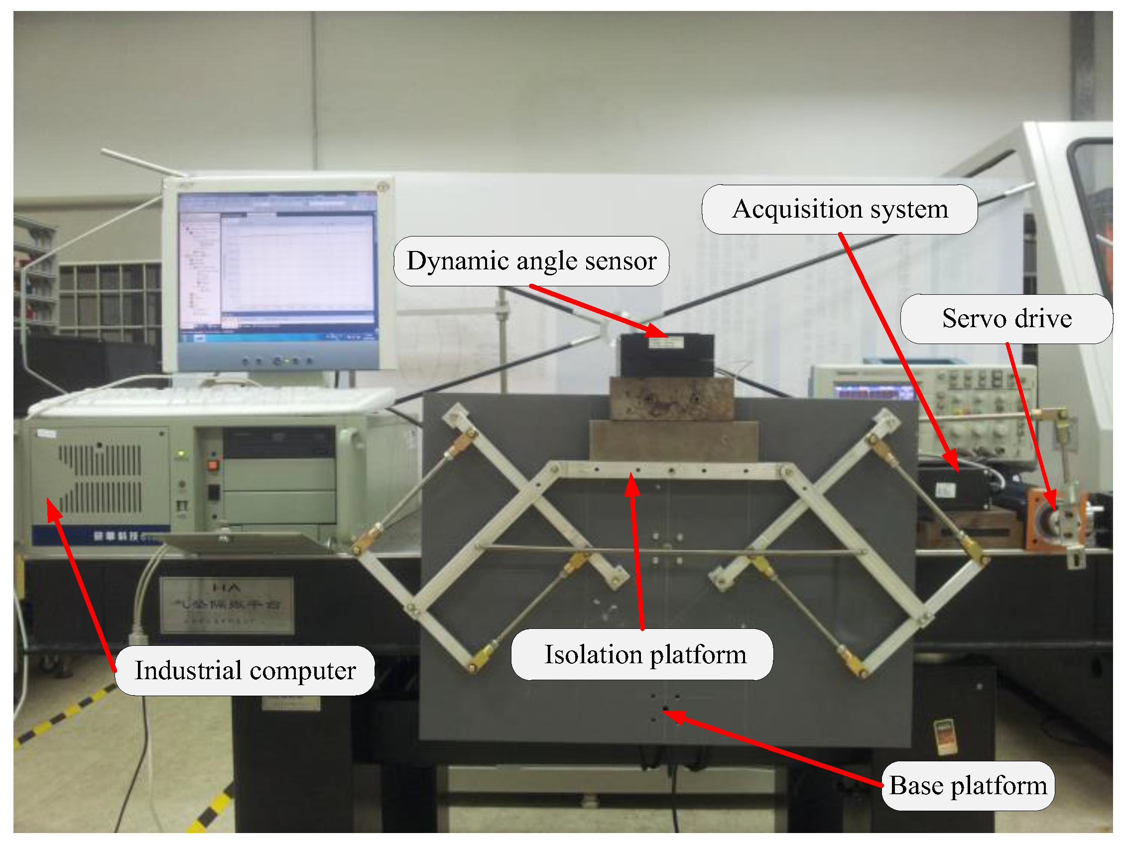
Figure 9 shows an experimental prototype system constructed based on the theoretical model. This system comprised a vibration isolation platform, input disturbance unit, measurement unit, and computer control unit. The base platform was driven by servo motors that linked the crank and rocker, which rotated around point . Accordingly, the displacement, velocity, and acceleration of the servo motor could be calculated based on the demand for input disturbance. The measurement unit comprised a MEMS tilt sensor, an AD acquisition system, and a computer. The tilt sensor was placed above the load and parallel to the vibration isolation platform, allowing simultaneous measurement of the angle from the platform to the horizontal line. The changing trajectory of the angle could then be observed on the computer screen.
5.2. Simulation and Analysis
Regarding the dynamic model described in Section 4, Equation (15) could be solved using MATLAB2015b software (MathWorks™, Natick, MA, USA), and different input parameters yielded different results.
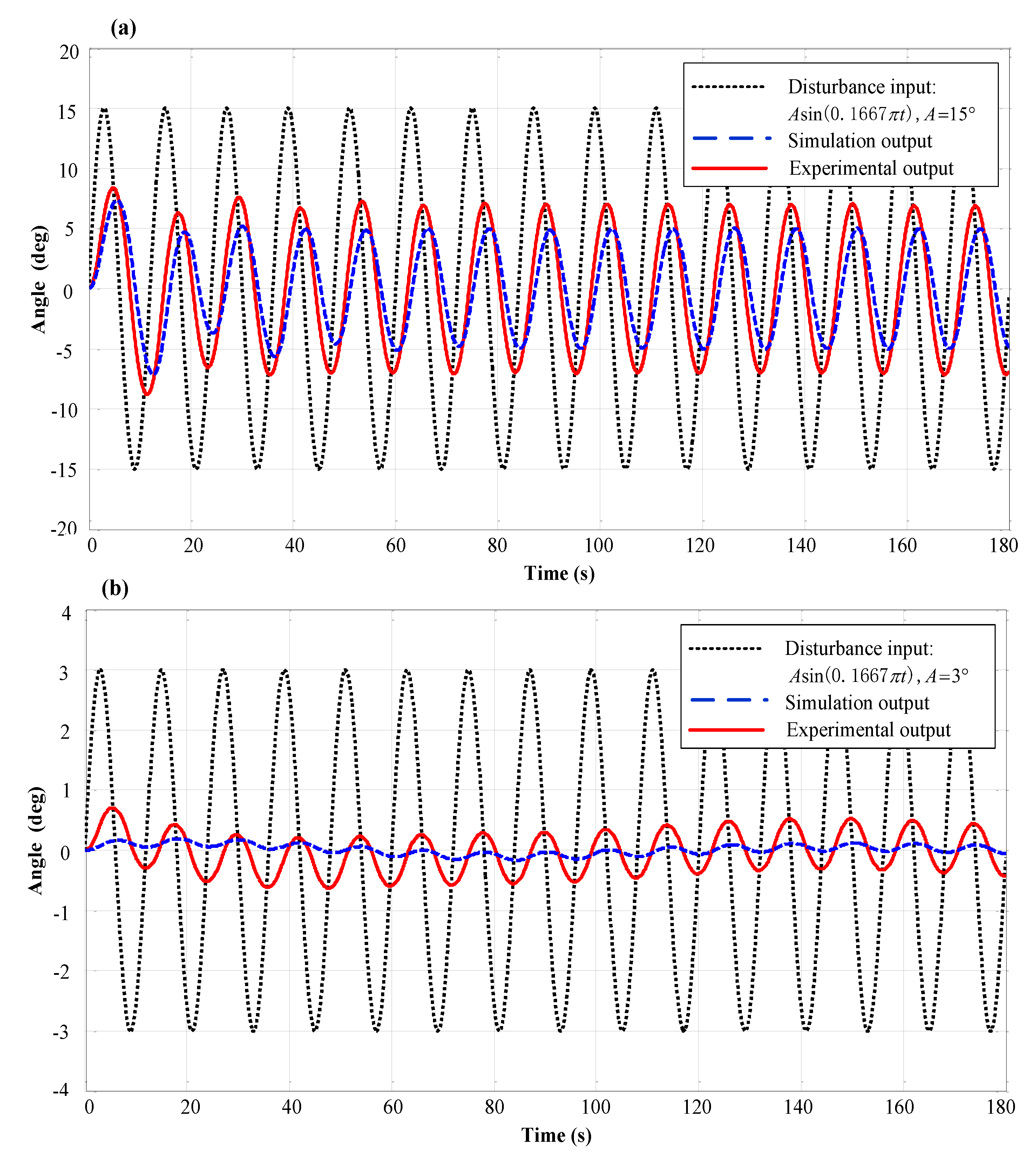
The simulation and experimental input parameters were set as follows. To mimic the influence of sea waves, which reportedly induce rocking motion periods of 3–12 s for ships [35], we set period T at 12 s and 3 s and amplitude A at 15° and 3°. The linear spring damp chain parameters k and c are equal to 200 N/m and 10 Nm/s, respectively. Figure 10 shows the simulation output and the experimental output at a disturbance frequency and different amplitudes.
Satisfactory vibration isolation is achieved with various inputted disturbance frequencies. In Figure 10a, the disturbance amplitude is theoretically expected to decrease by 66% at an input disturbance of . However, the experimental results show that the vibration attenuation is about 53%, which has a deviation of 2° from theoretical value. Also, the phase angle is smaller compared with theoretic calculation. However, the experimental and simulation results exhibited the same trend. Figure 10b shows good theoretical vibration isolation at a maximum amplitude of 0.26° and an input disturbance of , A = 3°. The experimental result varied greatly, with a maximum deviation of 0.62°. In addition, the experimental results also show that the amplitude of the isolation is almost the constant over time. However, there exist slight center drifts, and the periodic characteristics are shown with the time span about 140 s (≈12T), which corresponds to the results of the theoretical simulation. Overall, the isolation performance is good, despite the small deviation with the central position around 0°.
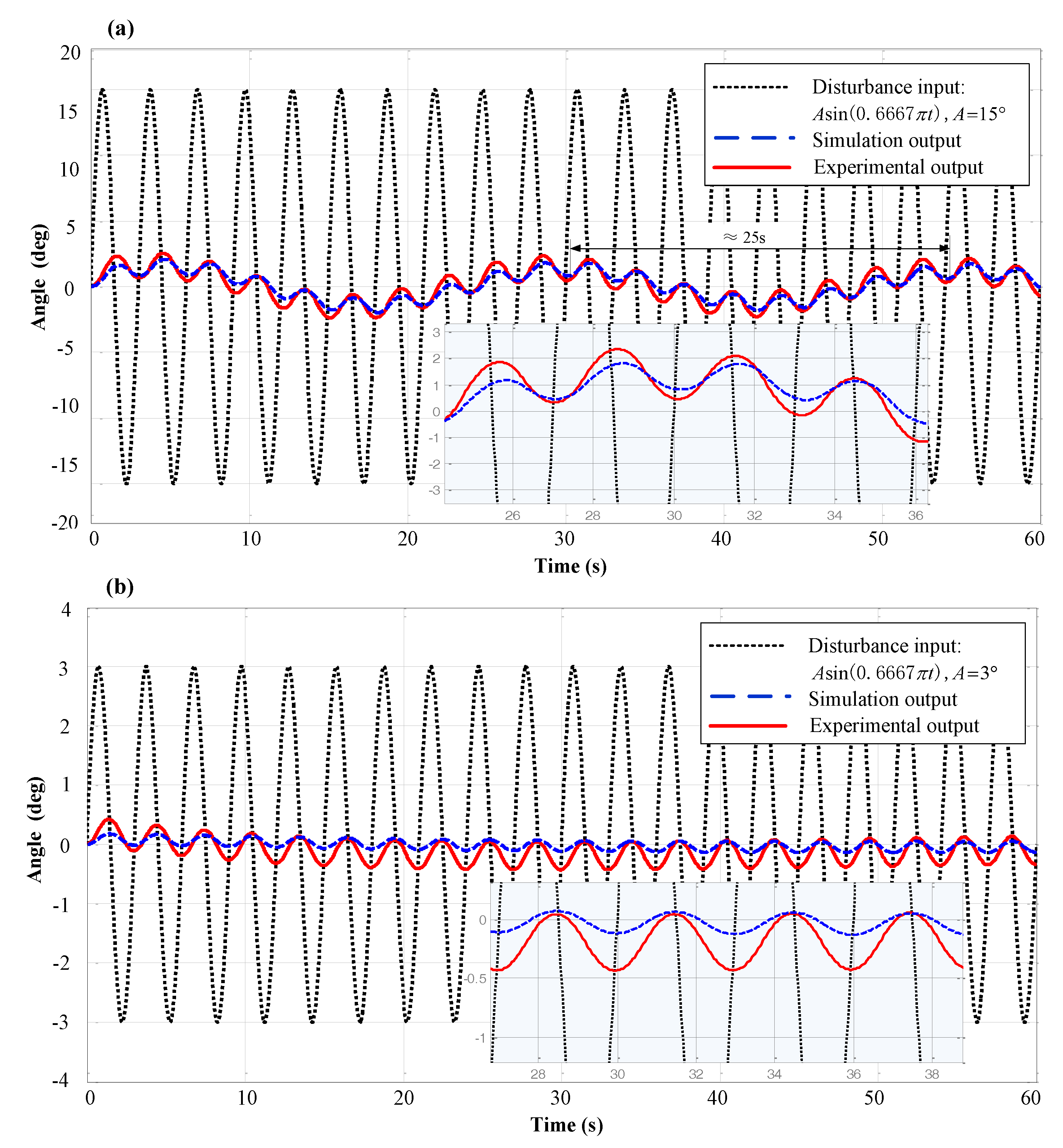
Figure 11 shows the results of a simulation and an experiment conducted at an input disturbance frequency of 0.3333 Hz and input amplitudes of 15° and 3°.
At an input disturbance of , 88% of the vibration is reduced. According to the simulation, the excitation amplitude is small when the output frequency fluctuated. The experimental results in Figure 11a demonstrate that the vibration attenuation is about 82%, and the actual deviation is quite small (≈0.8°) compared to the theoretical value. The results show that the amplitude of the isolation is almost constant during the experiment time. However, there exist slight center drifts, and the periodic characteristics are shown with the time span of about 25 s (≈8T), which corresponds to the results of the theoretical simulation. There are two reasons for the results. One is due to the joint friction caused by vibration isolation output from the center of the balance position; the other is because of the nonlinear characteristic caused by the inherent low-order harmonics of the system. At a low amplitude (3°), the maximum deviation was 0.27° (Figure 11b), indicating excellent theoretical vibration isolation. The experimental results demonstrated that the vibration amplitude was approximately 0.43° around the equilibrium position of 0°.
The former simulation and experimental results demonstrated that when exerting a disturbance with a large amplitude, a larger input disturbance frequency was associated with a greater reduction in vibration isolation, thus agreeing with findings from the linear spring isolator. At the same input disturbance frequency, a lower disturbance amplitude was associated with more effective isolation, in accordance with the principle of QZS. In other words, a high-static-low-dynamic isolator was more suitable for low-amplitude vibration isolation. Nevertheless, the deviations between the simulation and experimental results were large when low-amplitude vibrations were used. These deviations were attributed to three possible factors: greater rotation joint damping under actual compared with theoretic conditions; inaccurate static and dynamic friction coefficients at ultra-low speeds; and a reduced friction factor for the ball bearing at increased rocking speeds, which had a good influence on vibration isolation. Therefore, friction damping is a key factor in ultra-low-frequency vibration isolation that should be avoided as much as possible.
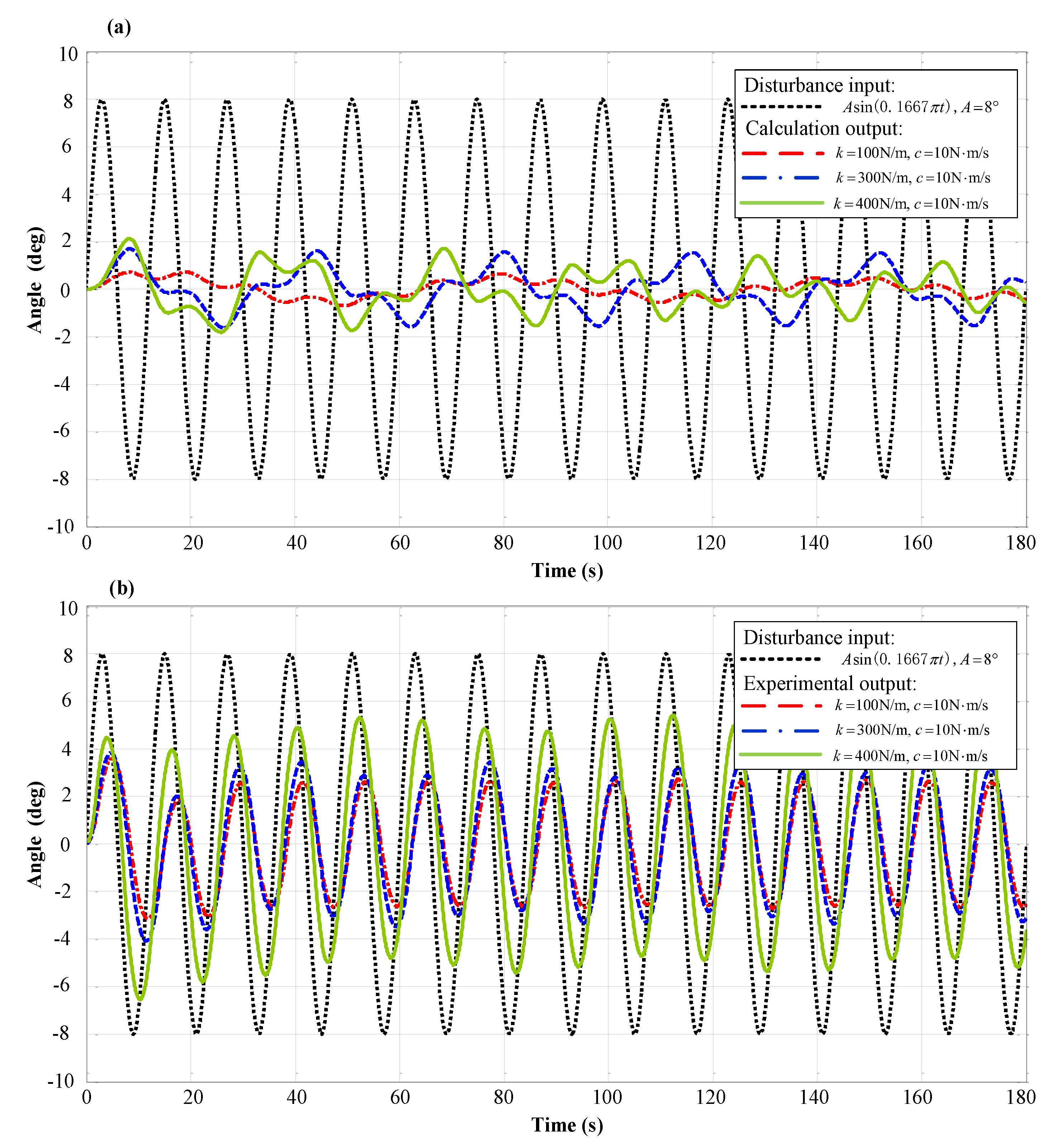
The influence of linear spring damping chain stiffness on isolator performance was also evaluated experimentally, using harmonic disturbances, T = 12 s, and A = 8° as the set inputs. Figure 12 shows the simulation and experimental outputs.
Figure 12 depicts the influence of linear stiffness on vibration isolator performance. Figure 12a clearly indicates poor performance with increasing stiffness (k). At very low chain damping coefficient values, large differences in isolation effectiveness are observed at k = 100 N/m and k = 300 N/m, due to the influence of damping. However, Figure 12b indicates similar vibration isolation performance under different stiffness levels, as both friction damping and spring damping interfered with isolation. With the extension of time, experimental results show that the system is in the steady state and vibration isolation performance is relatively good. The relatively similar simulation outputs at k = 400 N/m and k = 300 N/m indicate that linear stiffness was not a key factor affecting vibration isolation in this analysis. However, the experimental results contrasted with the simulation results, and indicated that damping, especially friction damping, had a large influence on vibration isolation. In other words, the influence of damping on ultra-low frequency vibration isolation cannot be ignored. Friction damping, spring chain damping, and changes in static and dynamic friction coefficients caused by friction damping warrant further consideration and discussion.
6. Conclusions
This paper proposes a novel, dual-parallelogram, passive rocking vibration isolator with QZS and demonstrated good vibration isolation performance via high-static-low-dynamic torsion stiffness. It discusses the dynamic models of different isolators and demonstrates that, through an analysis of four linear spring configuration schemes used to obtain HSLDS and QZS at the equilibrium position, the spring arrangement can be optimized and a dynamic model can be established based on the dynamic characteristics. Our experimental results verified our simulation results and confirmed the ability of this novel system to isolate vibrations.
A rocking vibration isolation scheme with a QZS mechanism could feasibly be constructed using linear spiral springs. A dual-parallelogram passive rocking vibration isolator with QZS has the advantages of a large bearing capacity, high precision, and good vibration isolation performance. At harmonic excitations of , and , , the experimental results indicated that vibration could be reduced by 53% and 86%, respectively, confirming the good capacity of this system of vibration isolation. In a high-static-low-dynamic vibration isolation system, transmissibility is closely related to the excitation amplitude. At an equilibrium position of QZS, better vibration isolation performance can be achieved with a low torsion excitation. Furthermore, the influence of friction damping on ultra-low frequency vibration isolation warrants thorough investigation.
Using our dynamic model of a novel, dual-parallelogram, passive rocking vibration isolator system, we were unable to simplify the mechanism to a single mass rocking around a fixed point, mainly because for most of the rods the motion comprised both translation and rotation, whereas others comprised only translation.
Acknowledgments
This work was financially supported by the foundation of Innovative Research Groups and the Joint Funds of the National Natural Science Foundation of China (Grant Nos. 51521003 and U1613201), in part by the Science and Technology Project of Guangdong, China (Grant No. 2016A010102004), and in part by Shenzhen Research Funds (JCYJ20150529141408781 and JCYJ20150529143500954).
Author Contributions
S.W. established the theoretical model and wrote this paper; P.G. analyzed the data. Y.H. designed the experiments; B.L. provided some key ideas and revised the manuscript.
Conflicts of Interest
The authors declare no conflicts of interest.
References
- Rivin, E.I. Passive Vibration Isolation; ASME Press: New York, NY, USA, 2001. [Google Scholar]
- Ibrahim, R.A. Recent advances in nonlinear passive vibration isolators. J. Sound Vib. 2008, 314, 371–452. [Google Scholar] [CrossRef]
- Carrella, A.; Brennan, M.J.; Waters, T.P. Static analysis of a passive vibration isolator with quasi-zero-stiffness characteristic. J. Sound Vib. 2007, 301, 678–689. [Google Scholar] [CrossRef]
- Kovacic, I.; Brennan, M.J.; Waters, T.P. A study of a nonlinear vibration isolator with a quasi-zero stiffness characteristic. J. Sound Vib. 2008, 315, 700–711. [Google Scholar] [CrossRef]
- Carrella, A.; Brennan, M.J.; Waters, T.P.; Lopes, V. Force and displacement transmissibility of a nonlinear isolator with high-static-low-dynamic-stiffness. Int. J. Mech. Sci. 2012, 55, 22–29. [Google Scholar] [CrossRef]
- Le, T.D.; Ahn, K.K. A vibration isolation system in low frequency excitation region using negative stiffness structure for vehicle seat. J. Sound Vib. 2011, 330, 6311–6335. [Google Scholar] [CrossRef]
- Ahn, H.J.; Lim, S.H.; Park, C. An integrated design of quasi-zero stiffness mechanism. J. Mech. Sci. Technol. 2016, 30, 1071–1075. [Google Scholar] [CrossRef]
- Carrella, A.; Brennan, M.J.; Waters, T.P.; Shin, K. On the design of a high-static–low-dynamic stiffness isolator using linear mechanical springs and magnets. J. Sound Vib. 2008, 315, 712–720. [Google Scholar] [CrossRef]
- Zhu, Y.; Li, Q.; Xu, D.; Hu, C.; Zhang, M. Modeling and analysis of a negative stiffness magnetic suspension vibration isolator with experimental investigations. Rev. Sci. Instrum. 2012, 83, 095108. [Google Scholar] [CrossRef] [PubMed]
- Wu, W.; Chen, X.; Shan, Y. Analysis and experiment of a vibration isolator using a novel magnetic spring with negative stiffness. J. Sound Vib. 2014, 333, 2958–2970. [Google Scholar] [CrossRef]
- Liu, X.; Huang, X.; Hua, H. On the characteristics of a quasi-zero stiffness isolator using Euler buckled beam as negative stiffness corrector. J. Sound Vib. 2013, 332, 3359–3376. [Google Scholar] [CrossRef]
- Huang, X.; Liu, X.; Sun, J.; Zhang, Z.; Hua, H. Vibration isolation characteristics of a nonlinear isolator using Euler buckled beam as negative stiffness corrector: A theoretical and experimental study. J. Sound Vib. 2014, 333, 1132–1148. [Google Scholar] [CrossRef]
- Zhou, J.; Wang, X.; Xu, D.; Bishop, S. Nonlinear dynamic characteristics of a quasi-zero stiffness vibration isolator with cam-roller-spring mechanisms. J. Sound Vib. 2015, 346, 53–69. [Google Scholar] [CrossRef]
- Winterflood, J.; Barber, T.; Blair, D.G. Using Euler buckling springs for vibration isolation. Class. Ouant. Grav. 2002, 19, 1639. [Google Scholar] [CrossRef]
- Hosain, M.A.; Sirr, A.; Ju, L.; Blair, D.G. Novel Euler-LaCoste linkage as a very low frequency vertical vibration isolator. Rev. Sci. Instrum. 2012, 83, 085108. [Google Scholar] [CrossRef] [PubMed]
- Li, G.; Hu, H.; Wu, K.; Wang, G.; Wang, L.J. Ultra-low frequency vertical vibration isolator based on LaCoste spring linkage. Rev. Sci. Instrum. 2014, 85, 104502. [Google Scholar] [CrossRef] [PubMed]
- Li, Q.; Zhu, Y.; Xu, D.; Hu, J.; Min, W.; Pang, L. A negative stiffness vibration isolator using magnetic spring combined with rubber membrane. J. Mech. Sci. Technol. 2013, 27, 813–824. [Google Scholar] [CrossRef]
- Zeng, X.; Zhang, L.; Yu, Y.; Shi, M.; Zhou, J. The Stiffness and Damping Characteristics of a Dual-Chamber Air Spring Device Applied to Motion Suppression of Marine Structures. Appl. Sci. 2016, 6, 74. [Google Scholar] [CrossRef]
- Liu, J.; Ju, L.; Blair, D.G. Vibration isolation performance of an ultra-low frequency folded pendulum resonator. Phys. Lett. A 1997, 228, 243–249. [Google Scholar] [CrossRef]
- Barone, F.; Giordano, G.; Acernese, F.; Romano, R. Large band high sensitivity motion measurement and control of spacecrafts and satellites. Proc. SPIE 2016, 9803, 98034G. [Google Scholar]
- Losurdo, G.; Bernardini, M.; Braccini, S.; Bradaschia, C.; Casciano, C.; Dattilo, V.; Gennai, A. An inverted pendulum preisolator stage for the VIRGO suspension system. Rev. Sci. Instrum. 1999, 70, 2507–2515. [Google Scholar] [CrossRef]
- Takamori, A.; Raffai, P.; Márka, S.; DeSalvo, R.; Sannibale, V.; Tariq, H.; Takahashi, R. Inverted pendulum as low-frequency pre-isolation for advanced gravitational wave detectors. Nuclear Instrum. Methods Phys. Res. Sect. A 2007, 582, 683–692. [Google Scholar] [CrossRef]
- Bosetti, P.; Biral, F.; Bortoluzzi, D. Design, manufacturing, and performance verification of a Roberts linkage for inertial isolation. Precis. Eng. 2014, 38, 138–147. [Google Scholar] [CrossRef]
- Winterflood, J.; Blair, D.G. A long-period conical pendulum for vibration isolation. Phys. Lett. A 1996, 222, 141–147. [Google Scholar] [CrossRef]
- Wu, X.W.; Cheng, Y.J.; Chen, Y.J.; Wang, W. A research of conical pendulum low-frequency horizontal displacement apparatus. Mach. Design Manuf. 2007, 10, 053. [Google Scholar]
- Matta, E.; De Stefano, A.; Spencer, B.F. A new passive rolling-pendulum vibration absorber using a non-axial-symmetrical guide to achieve bidirectional tuning. Earthq. Eng. Struct. D 2009, 38, 1729–1750. [Google Scholar] [CrossRef]
- Shaw, A.D.; Neild, S.A.; Wagg, D.J. Dynamic analysis of high static low dynamic stiffness vibration isolation mounts. J. Sound Vib. 2013, 332, 1437–1455. [Google Scholar] [CrossRef]
- Harvey, P.S., Jr.; Wiebe, R.; Gavin, H.P. On the chaotic response of a nonlinear rolling isolation system. Phys. D Nonlinear Phenom. 2013, 256, 36–42. [Google Scholar] [CrossRef]
- Wang, X.; Zhou, J.; Xu, D.; Ouyang, H.; Duan, Y. Force transmissibility of a two-stage vibration isolation system with quasi-zero stiffness. Nonlinear Dyn. 2017, 87, 633–646. [Google Scholar] [CrossRef]
- Abbasi, A.; Khadem, S.E.; Bab, S.; Friswell, M.I. Vibration control of a rotor supported by journal bearings and an asymmetric high-static low-dynamic stiffness suspension. Nonlinear Dyn. 2016, 85, 525–545. [Google Scholar] [CrossRef]
- Zhou, J.; Xu, D.; Bishop, S. A torsion quasi-zero stiffness vibration isolator. J. Sound Vib. 2015, 338, 121–133. [Google Scholar] [CrossRef]
- Abbasi, A.; Khadem, S.E.; Bab, S. Vibration control of a continuous rotating shaft employing high-static low-dynamic stiffness isolators. J. Vib. Control 2016. [Google Scholar] [CrossRef]
- Xue, S.D.; Ko, J.M.; Xu, Y.L. Optimum parameters of tuned liquid column damper for suppressing pitching vibration of an undamped structure. J. Sound Vib. 2000, 235, 639–653. [Google Scholar] [CrossRef]
- Wei, S.; Hua, L.L.; Hong, Z. Influence of sway motion on passive anti-rolling tank. J. Mar. Sci. Appl. 2006, 5, 17–22. [Google Scholar] [CrossRef]
- Lewis, E.V. The motion of ships in waves. In Principles of Naval Architecture; The Society of Naval Architect and Marin Engineers: New York, NY, USA, 1967; pp. 628–634. [Google Scholar]
Figure 1.
Mechanistic diagram of the vibration isolator.
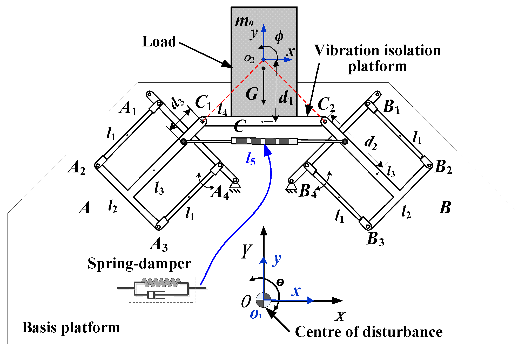
Figure 2.
Motion diagram of the dual-parallelogram vibration isolation.

Figure 3.
(a) The equivalent relationship between the torque and angle at ; (b) Distribution of the equivalent torsional stiffness.
Figure 3.
(a) The equivalent relationship between the torque and angle at ; (b) Distribution of the equivalent torsional stiffness.
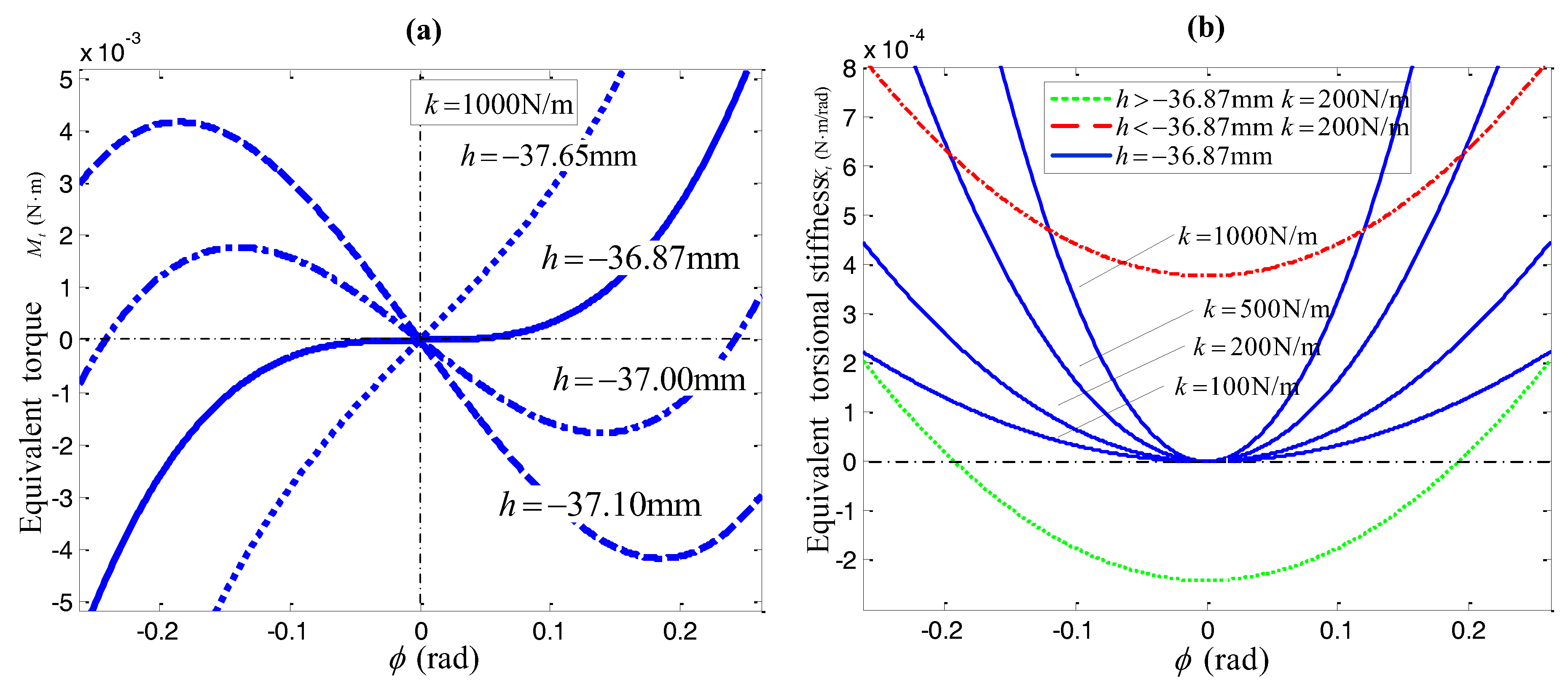
Figure 4.
(a) Equivalent stiffness and error curves; (b) Error distribution.

Figure 5.
Four linear spring configuration schemes. (a) Spring-damping connects two main branches; (b) Spring-damping connects two parallelograms; (c) Spring-damping connects parallelogram and base platform; (d) Spring-damping connects vibration isolation platform and base platform.
Figure 5.
Four linear spring configuration schemes. (a) Spring-damping connects two main branches; (b) Spring-damping connects two parallelograms; (c) Spring-damping connects parallelogram and base platform; (d) Spring-damping connects vibration isolation platform and base platform.
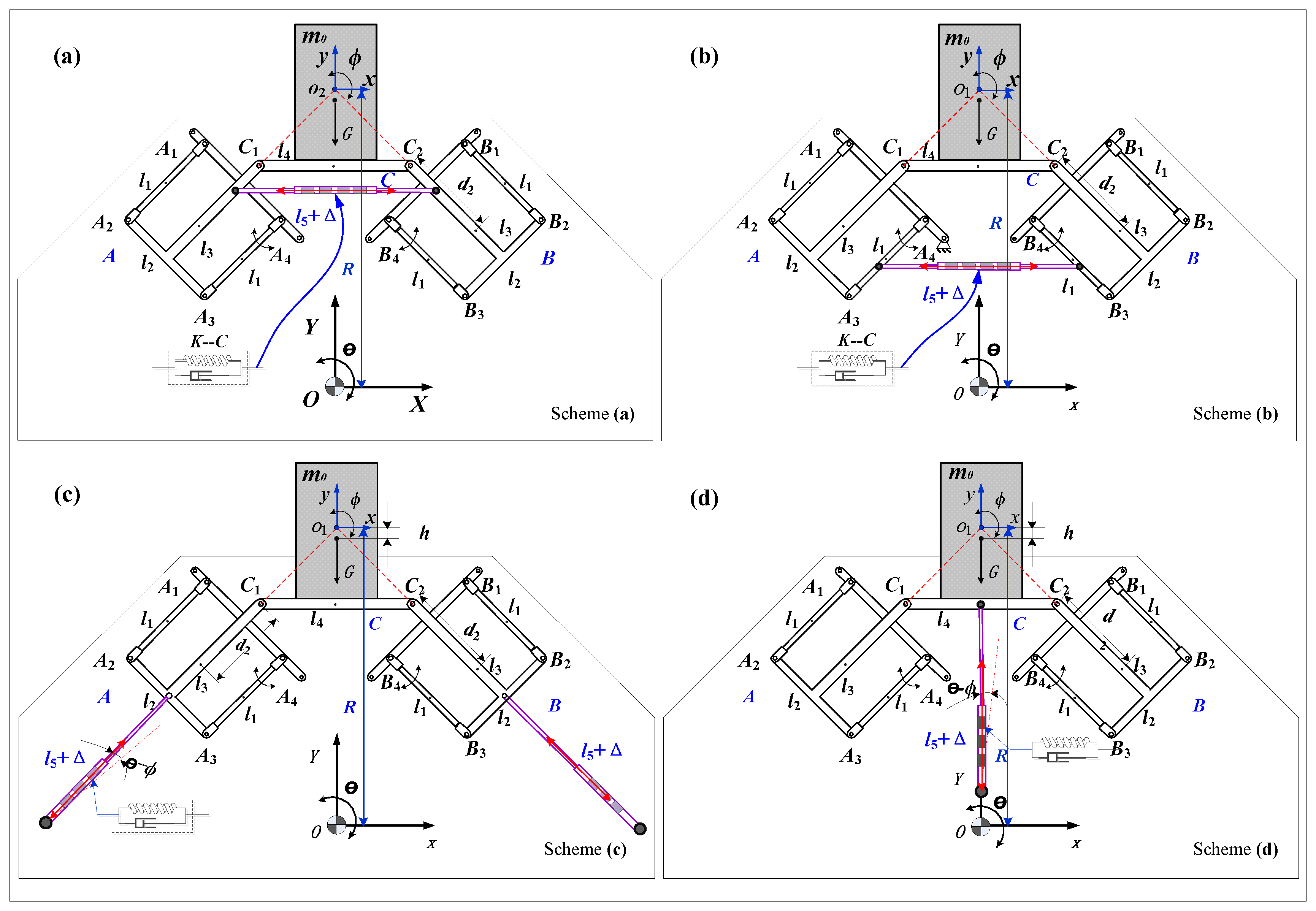
Figure 6.
Comparison curves of equivalent torsional stiffness.

Figure 7.
Transmissibility of vibration isolation.
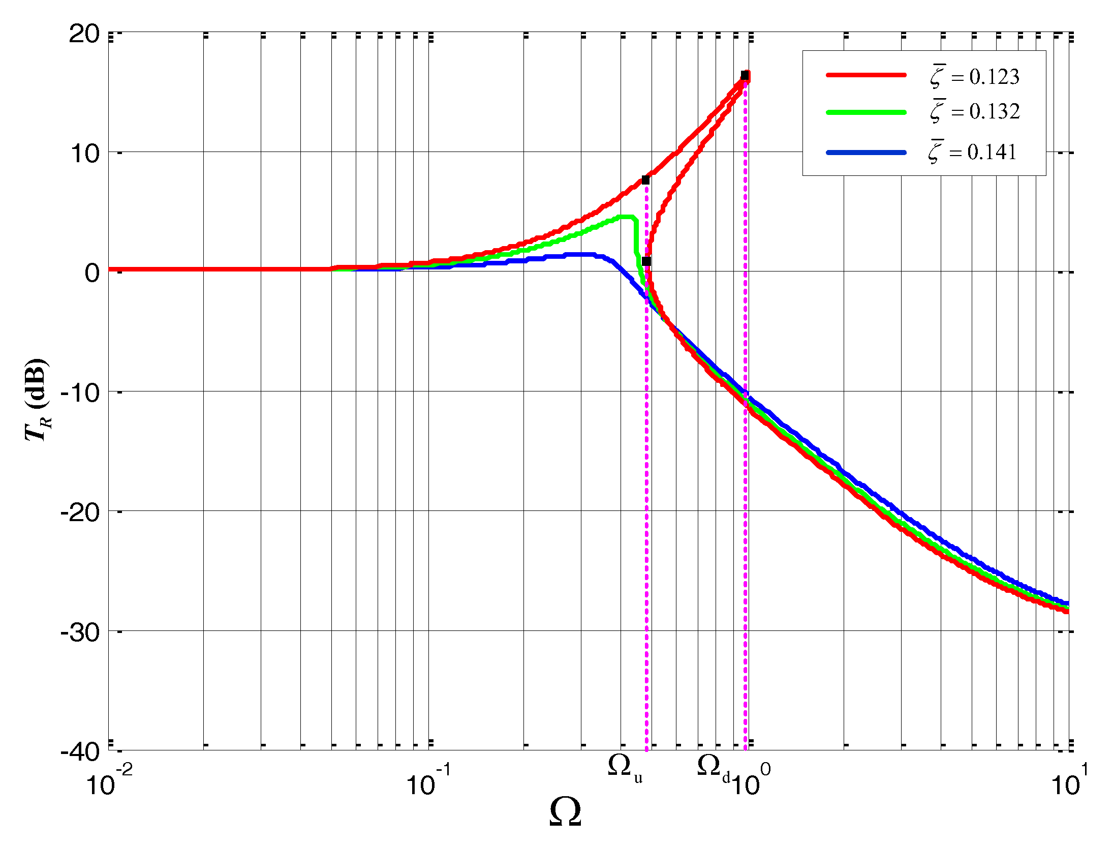
Figure 8.
The influence of input disturbance amplitude on transmissibility.

Figure 9.
Experimental vibration isolation system.

Figure 10.
Simulation and experimental outputs at f = 0.0833. (a) A = 15°, simulation and experimental output; (b) A = 3°, simulation and experimental output.
Figure 10.
Simulation and experimental outputs at f = 0.0833. (a) A = 15°, simulation and experimental output; (b) A = 3°, simulation and experimental output.

Figure 11.
Simulation and experimental outputs at f = 0.3333. (a) A = 15°, simulation and experimental output; (b) A = 3°, simulation and experimental output.
Figure 11.
Simulation and experimental outputs at f = 0.3333. (a) A = 15°, simulation and experimental output; (b) A = 3°, simulation and experimental output.

Figure 12.
Influence of spring stiffness on isolation performance. (a) Simulation output; (b) experimental output.
Figure 12.
Influence of spring stiffness on isolation performance. (a) Simulation output; (b) experimental output.

Table 1.
Mechanistic parameters.
| Geometrical Parameters (mm) | Mass Parameters (kg) | Moment of Inertia (kg·m2) |
|---|---|---|
| - | - | |
| - | - |
© 2017 by the authors. Licensee MDPI, Basel, Switzerland. This article is an open access article distributed under the terms and conditions of the Creative Commons Attribution (CC BY) license (http://creativecommons.org/licenses/by/4.0/).
Share and Cite
MDPI and ACS Style
Wang, S.; Gao, P.; Hu, Y.; Li, B. A Novel Dual–Parallelogram Passive Rocking Vibration Isolator: A Theoretical Investigation and Experiment. Appl. Sci. 2017, 7, 367. https://doi.org/10.3390/app7040367
AMA Style
Wang S, Gao P, Hu Y, Li B. A Novel Dual–Parallelogram Passive Rocking Vibration Isolator: A Theoretical Investigation and Experiment. Applied Sciences. 2017; 7(4):367. https://doi.org/10.3390/app7040367
Chicago/Turabian StyleWang, Shuai, Peng Gao, Ying Hu, and Bing Li. 2017. "A Novel Dual–Parallelogram Passive Rocking Vibration Isolator: A Theoretical Investigation and Experiment" Applied Sciences 7, no. 4: 367. https://doi.org/10.3390/app7040367
Note that from the first issue of 2016, this journal uses article numbers instead of page numbers. See further details here.