
Formation of Boundary Film from Ionic Liquids Enhanced by Additives


1
Division of Machine Elements, Department of Engineering Sciences and Mathematics, Luleå University of Technology, Luleå SE-97187, Sweden
2
Chemical Technology, Luleå University of Technology, Luleå SE-97187, Sweden
*
Author to whom correspondence should be addressed.
Appl. Sci. 2017, 7(5), 433; https://doi.org/10.3390/app7050433
Submission received: 5 March 2017
/
Revised: 12 April 2017
/
Accepted: 20 April 2017
/
Published: 26 April 2017
(This article belongs to the Special Issue Lubricant Additives)
Abstract
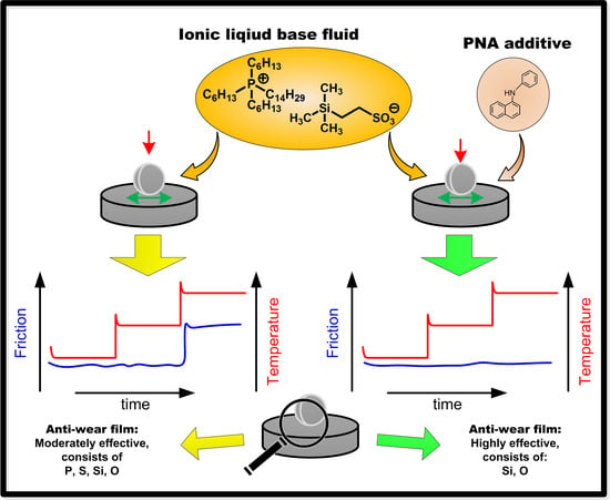
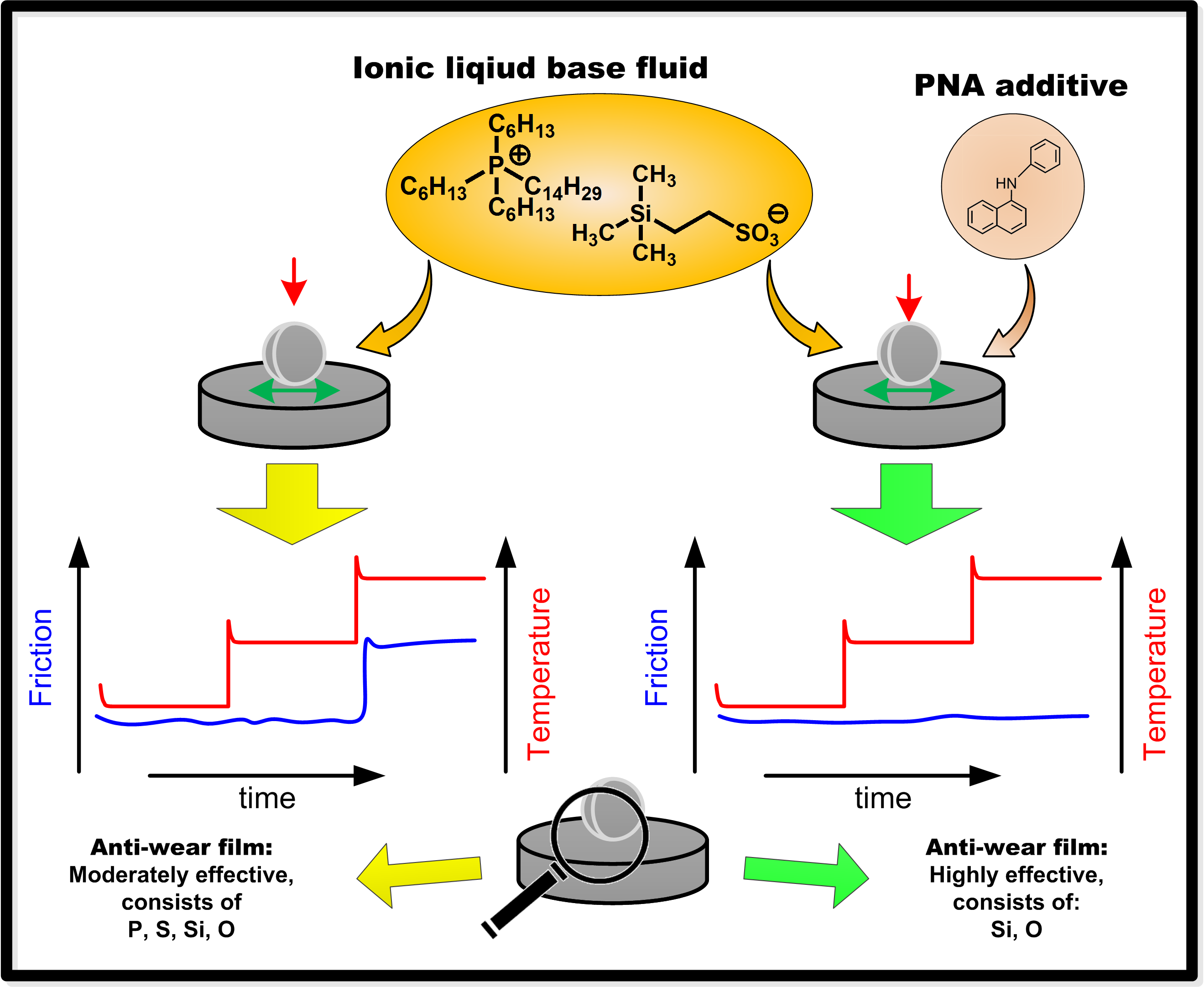
:Room temperature ionic liquids (RTILs) have several properties that make them interesting candidates as base fluids for extreme conditions. However, a lack of compatibility with tribo-improving additives combined with an often overly aggressive nature is limiting their use as base fluids. To overcome these drawbacks, hydrocarbon-imitating RTIL base fluids have recently been developed. In this study, the effects of several common additives in the novel RTIL (P-SiSO) were examined by laboratory tribotesting. A reciprocating steel-steel ball-on-flat setup in an air atmosphere was used, where the lubricant performance was evaluated over a range of loads and temperatures. Surface analyses after testing were carried out using optical profilometry, scanning electron microscopy (SEM), and energy dispersive X-ray spectroscopy (EDS). Neat P-SiSO displayed high performance in the tribotests. At an elevated load and temperature, a shift in lubrication mode was observed with an accompanying increase in friction and wear. Surface analysis revealed a boundary film rich in Si and O in the primary lubrication mode, while P was detected after a shift to the secondary lubrication mode. An amine additive was effective in reducing wear and friction under harsh conditions. The amine was determined to increase formation of the protective Si–O film, presumably by enhancing the anion activity.
1. Introduction
Lubricants enable the efficient and reliable operation of moving mechanical assemblies by reducing friction and wear. Ideally, a lubricant film fully separates the moving surfaces so that wear is minimized and friction is limited to shearing of the viscous film. Unfortunately, there are many cases where the fluid film cannot be maintained and the asperities of the surfaces come into direct contact (i.e., the system operates in the mixed or boundary lubrication regime). To avoid excessive wear in these regimes, wear and friction reducing additives are required.
The past century has seen the development of an extensive set of lubricant additives that can significantly improve the tribological performance of hydrocarbon oils in combination with steel surfaces [1,2]. Predicting additive effectiveness; however, is very complex. The additive performance is well known to be dependent on the entire tribosystem, meaning that the effect of base fluids, surface materials, and operating conditions all must be considered [3]. Our understanding of tribo-improving additives is still evolving, and significant clues on the mechanisms of these are still being uncovered [4,5].
Boundary lubrication (BL) additives are generally categorized as extreme pressure (EP) or anti-wear (AW) additives and form boundary films by adsorption on metal surfaces followed by chemical reaction [6]. AW films form a protective film that shields the underlying surface, whereas sacrificial EP films can actually increase wear, but are used to prevent catastrophic seizure [3]. The mechanism of film formation implies that two rates must be controlled: first, the rate of adsorption onto the surface; and second, the rate of formation of the reacted films, which must be balanced in accordance to the operational conditions faced [7]. To correctly balance both rates in practical applications is a challenging task that is further complicated by interference between different additives, as well as the influence of the base fluid quality. Therefore, arriving at successful lubricant formulations (base oil and additive combination) has been largely empirical in nature.
Synthetic base fluids are increasingly being relied upon to meet requirements of low volatility and thermal stability; however, the additive technology developed for hydrocarbon base fluids is not necessarily applicable due to the significant difference in chemical structure between the traditional hydrocarbon base fluids and the novel advanced synthetic fluids. In many cases, the conventional additives are not miscible [8,9]. In other cases, if the base fluid is very polar, miscibility may become excessive, resulting in a low affinity for the metal surfaces it should protect [10].
Room temperature ionic liquids (RTILs) are a class of advanced synthetic fluids that are highly polar as the fluids consist entirely of cations and anions [11,12,13,14]. These fluids were first suggested as advanced lubricating fluids in 2001 in Reference [15]. As described in Reference [16], they have been intensely researched in many fields, including tribology, over the past two decades. The ionic nature means that RTILs readily adsorb on metal surfaces and under tribological conditions can form boundary films, even as neat fluids [17,18]. However, as mentioned above, optimum reactivity depends on the entire tribosystem, and even though RTIL properties can be tailored by modifying their chemical structure, this is inefficient compared to the approach of base fluid–additive systems. Additives provide the option to fine tune lubricant performance to meet the demands of specific operational conditions without redesigning the base fluid. There have been many attempts with both conventional and unconventional additives for RTILs [19,20,21,22,23], but inherently high reactivity remains problematic. However, in our recent work, hydrocarbon-mimicking ionic liquids have been designed for use as base fluids to reduce the inherent reactivity and enable compatibility with existing additives [24].
In this work, additive technology for RTILs was investigated by use of a hydrocarbon-mimicking ionic liquid in a reciprocating steel–steel ball-on-flat tribotest. In our previous work [24], it was found that neat RTIL lubricants—designated as P-SiSO—showed low friction and wear in this type of tribotest, at 25 °C and maximum Hertz pressure up to 2.4 GPa. Friction performance was seen to remain low and steady for elevated loads up to 3.0 GPa at 25 °C, and common lubricant additives were seen to influence friction; however, no surface analysis was performed at elevated loads or for the additivated samples, so the effect on wear was not determined. Therefore, in this study, surface analysis post-testing were carried out by optical profilometry, scanning electron microscopy (SEM), and energy dispersive X-ray spectroscopy (EDS). The first objective was to determine the limits of the operational envelope, i.e., at what conditions in this tribotest does the tribological performance of neat P-SiSO deteriorate so that low friction and wear can no longer be maintained. The second objective was to investigate the effect of additives on extending the operational envelope of P-SiSO.
2. Materials and Methods
2.1. Lubricant Properties
A hydrocarbon-mimicking RTIL with the chemical formula [(n-C6H13)3(n-C14H29)P]·[(CH3)3SiC2H4SO3]—designated as P-SiSO—was used as the base fluid in these experiments. P-SiSO was synthesized by Nisshinbo Holdings Inc. (Tokyo, Japan), and the molecular design of P-SiSO has been described in Reference [24]. A low vapor pressure fluid (Fomblin Y 317950)—designated as PFPE—was supplied by Sigma-Aldrich (Stockholm, Sweden) and used as the reference lubricant. The linear formula of PFPE is CF3O[–CF(CF3)CF2O–]x(–CF2O–)yCF3, and its molecular weight is 3300 g/mol.
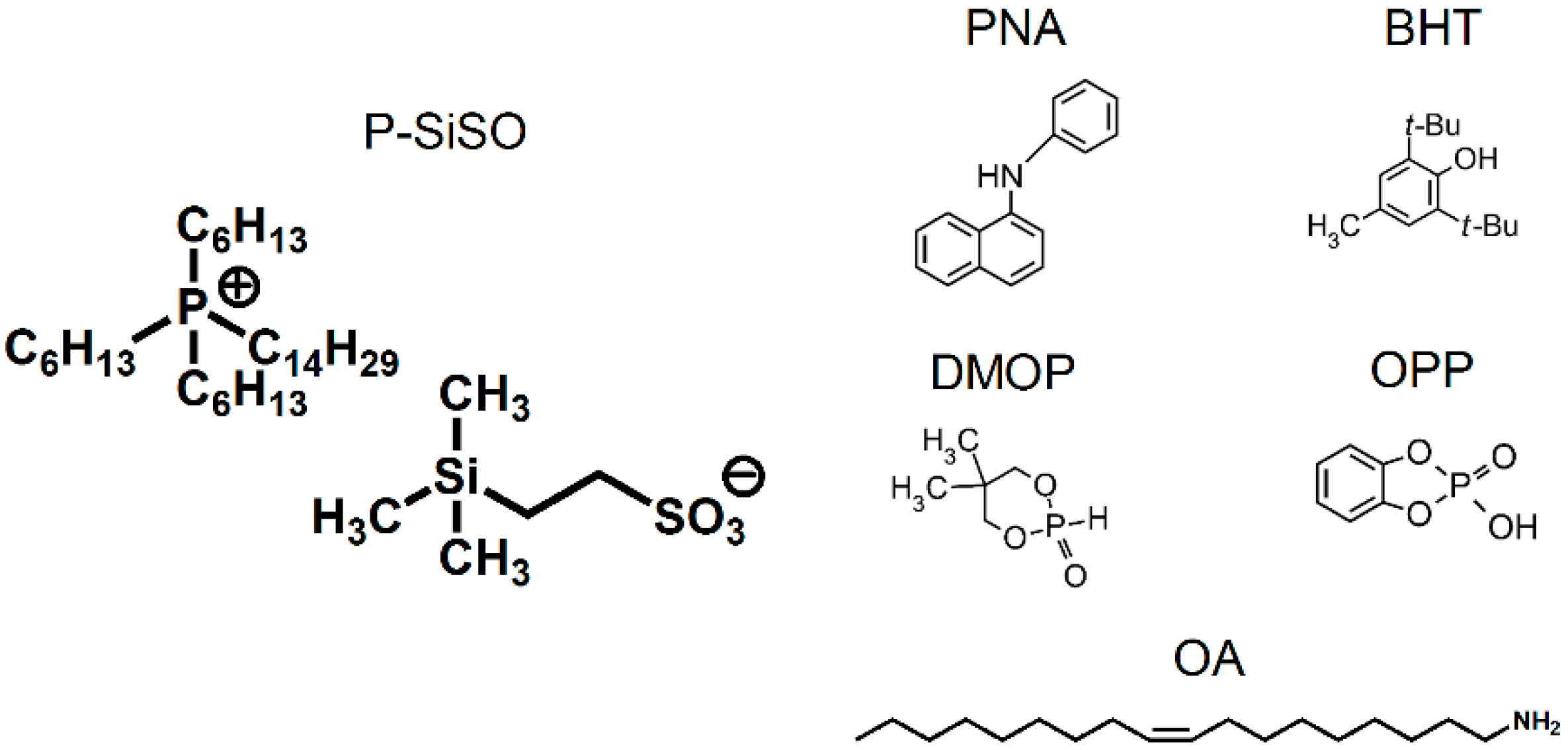
Five different additives were used, and are referred to as OA, PNA, DMOP, BHT, and OPP, and their respective detailed description is provided below. Oleylamine (OA) (80–90% C-18, primary amines >98%), was supplied by Fisher Scientific (Göteborg, Sweden); and N-Phenyl-1-naphthylamine (PNA) (reagent grade, 98%), 5,5-dimethyl-1,3,2-dioxaphosphorinan-2-one (DMOP) (96%), and 2,6-di-tert-butyl-4-methylphenol (BHT) (>99%) were supplied by Sigma-Aldrich (Stockholm, Sweden). Ortho-phenylene phosphate (OPP) was prepared as described in Reference [25]. These five additives were used to prepare seven lubricant samples with P-SiSO as the base fluid: five single additive samples, and two samples where OPP was combined with either of the amines (OA, PNA), as synergistic effects between OPP and OA have previously been reported in Reference [25]. In all samples, the additives were added at a concentration of 10 mmol/kg. The chemical structures of the ionic liquid base fluid and the five additives are depicted in Figure 1. Density and viscosity properties can be found in the Supplementary Information (SI).
2.2. Ball-on-Flat Reciprocating Tribotest
An Optimol SRV tribotester in the ball-on-flat configuration was used to evaluate the lubrication performance of the lubricant samples with respect to friction and wear. This involved continuously measuring the friction force and analyzing the post-tribotest wear scars, along the lines of the standard tribotest ASTM D6425-11. In accordance with the test standard, a 10 mm ball was pressed against the top of a flat stationary disc while being subjected to a linearly reciprocating motion with an amplitude of 1.0 mm and frequency of 50 Hz. Prior to starting a test, a small amount of the lubricant being tested was applied onto the disc at the area of contact. The ball and disc were made of the AISI 52100 bearing steel as specified in the test standard. All the tests were conducted in air, with the relative humidity being ~25%. The test temperature was controlled by heating the disc support.
Three parameters were varied during the tests in this study: normal load, test temperature, and test duration, denoted by L (N), T (°C), and D (min) respectively. These were either held constant (denoted C) or were varied (denoted V) during the test. The following code was used to indicate the conditions in the various cases: C{L/T/D} or V{L1–L2/T1–T2/D}, where the subscript 1 indicates the nominal minimum value, while subscript 2 indicates the nominal maximum value of a parameter being varied during the test. Tests performed at different conditions were classified into two sections: (1) determining a performance envelope of neat P-SiSO; and (2) determining the effect of the additives on P-SiSO performance.
To determine the limits of the operational envelope when using neat P-SiSO, three tests were made (Stage 1). These tests used varying loads and temperatures in a manner similar to experiments in Reference [24], but with a focus on surface analysis as well as friction response. In the first test, V{100–300 N/25 °C/120 min}, the lubricant was evaluated by increasing the load in increments from 100 N to 300 N (corresponding to maximum Hertzian pressures of 2.1–3.0 GPa), at constant temperature, for a total test duration of 120 min. In the second test the temperature was increased stepwise at constant load V{150 N/40–100 °C/80 min}, and finally the temperature was increased stepwise at the maximum load of 300 N, i.e., V{300 N/40–80 °C/60 min}.
The additives were evaluated by three different test settings in Stage 2. The first of them, C{150 N/25 °C/30 min} can be considered as the initial screening of the additives. This test was conducted at constant load and room temperature (~25 °C), with the test duration being 30 min in length. The load was held constant at 150 N, corresponding to a maximum Hertzian pressure of 2.4 GPa. In the second test and third tests, the conditions were more severe using conditions V{300 N/40–80 °C/60 min} and C{300 N/80 °C/30 min}. The test codes and objectives are summarized in Table 1.
2.3. Surface Analysis
2.3.1. Quantification of Wear
The degree of wear was quantified by means of wear scar analyses performed using 3D optical surface profiling by white light interferometry using a Zygo NewView 7300 instrument (Zygo Corporation, Middlefield, CT, USA). In this work, the measured wear scar diameter (WSD) is reported in relation to the Hertzian contact diameter (HzD) [26], by a parameter designated as [27]. Furthermore, it was assumed that the wear scar diameter would never be less than the Hertz contact diameter, since the tests were started from standstill with a full load applied and therefore the initial contact patch would inevitably be scratched. Thus, the following condition holds, and was used to quantify wear:
2.3.2. SEM-EDS
SEM and EDS were used for recording high magnification images and analyzing the chemical composition of tribofilms, respectively. A low accelerating voltage of 3 kV was employed to resolve the thin tribofilms using a Magellan 400 FEG-SEM (FEI Company, Eindhoven, The Netherlands). The samples were not coated with any conductive coating prior to inspection. In addition, compositional mapping was performed by EDS using an X-Max 80 mm2 X-ray detector (Oxford Instruments, Abingdon, UK). EDS analysis was performed at an accelerating voltage of 5 kV, which was sufficient to detect the elements contained in the tribofilms (i.e., C, O, Si, P and S) while limiting beam penetration inside the steel substrate.
3. Results and Discussion
3.1. Stage 1: Limits of Operational Envelope of Neat P-SiSO
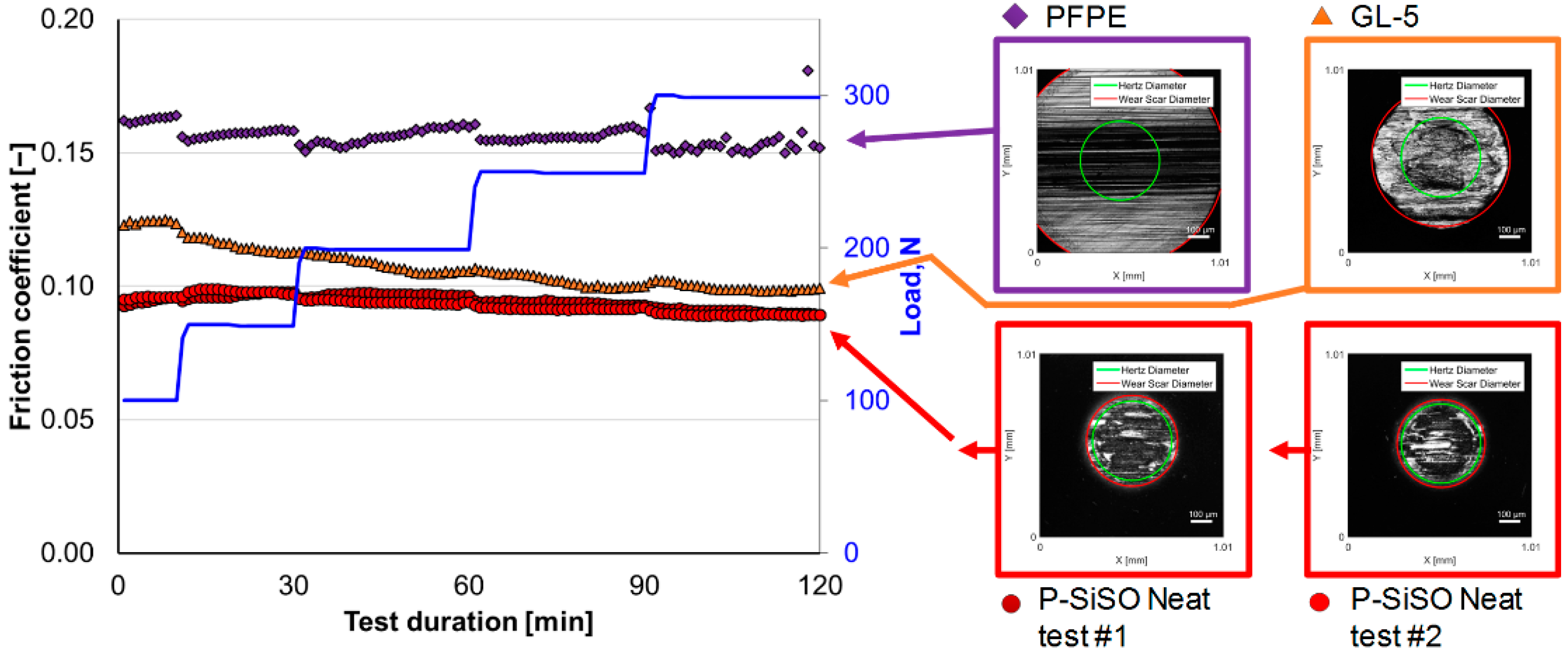
The measured friction coefficient as a function of test duration for neat P-SiSO, the reference lubricant PFPE, as well as a GL-5 fully formulated gear oil (see SI for details) at test conditions V{100–300 N/25 °C/120 min} are shown in Figure 2. Two test runs of P-SiSO are shown to visualize repeatability. The GL-5 gear oil is seen to follow the typical behavior expected for traditional lubricants containing EP and AW additives. EP additives are well-known to provide reduced friction at high load; however, this usually comes at the expense of increased wear [28]. In contrast, the anti-wear additives are normally active at lower loads, where they prevent wear, but generally increase friction [2]. The neat P-SiSO generates a low and steady friction coefficient that decreases with increased load. Furthermore, at the maximum load (corresponding to a Hertzian contact pressure of 3.0 GPa), the friction coefficient stabilizes around 0.90, which was the lowest friction recorded in the test. However, in contrast to the GL-5 lubricant, the neat P-SiSO also resulted in very low wear with , compared to for GL-5. The PFPE reference fluid on the other hand, generated a high friction-coefficient (ca. 0.16) that deteriorated at the highest load, and the WSD was at the limit of what could be measured with the setup used, . This was also in line with the well-known poor boundary lubrication performance by PFPE that has often been seen in similar tests [15,29,30].
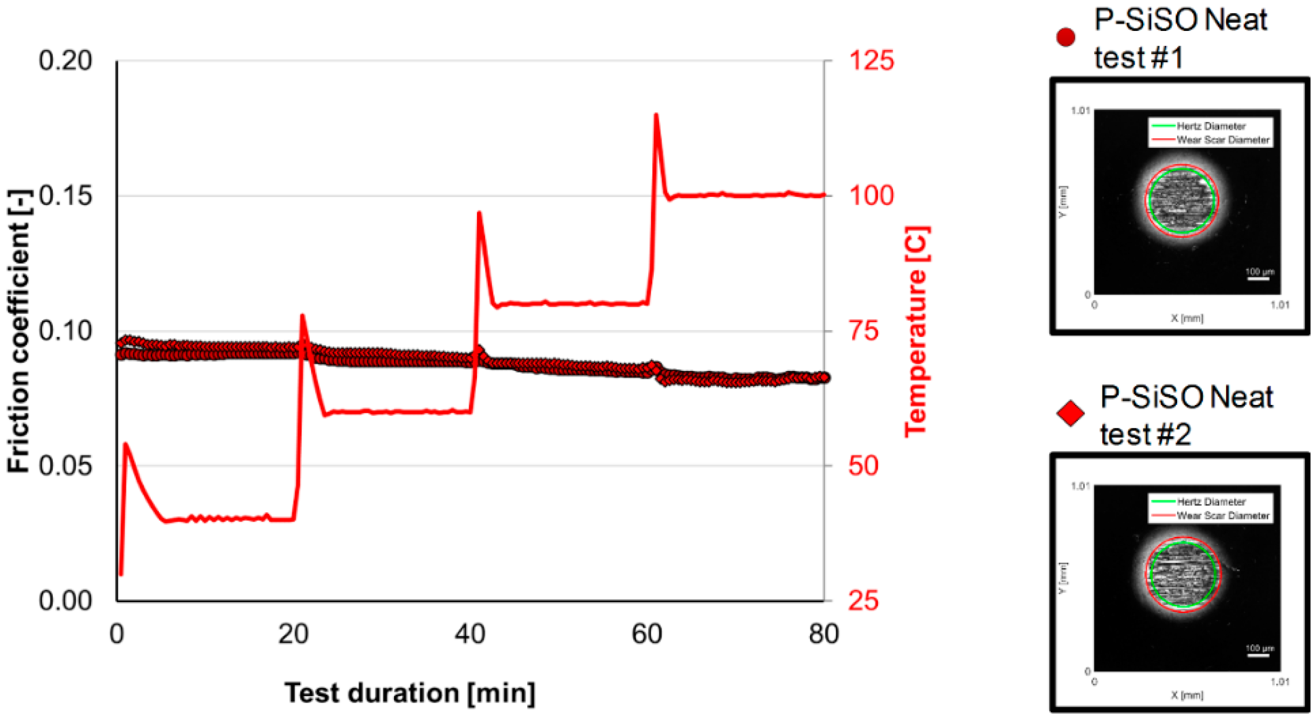
The results from the tribotest with neat P-SiSO, during conditions V{150 N/40–100 °C/80 min}, are displayed in Figure 3. Two repeated tests are shown to illustrate the repeatability. Again for P-SiSO, friction and wear remained low for the whole duration of the test, and reached a minimum at the final stage. It can be clearly seen that there is an overshoot in temperature at each step increase. However, it should be noted that the temperature is measure in the heated disc support, so the effect in the actual contact can be expected to be lower. Still, an effect can be seen where the friction immediately rises before recovering and stabilizing at a level that is lower than seen before the increased temperature. The increase in temperature is likely to promote boundary film formation by providing energy for a chemical reaction between lubricant and surface. The friction coefficient appeared to level out at around 100 °C at 0.83. The wear parameter after the completed test was determined as . When comparing the ball wear scar morphology to the ones obtained from tests at a higher load but lower temperature (V{100–300 N/25 °C/120 min}), a slight difference in intensity of the reflected light was seen.
Images of the disc surfaces after testing at V{150 N/40–100 °C/80 min} are shown in Figure 4. Figure 4a was recorded from the optical interferometric profilometer using 2.5× optical magnification. The wear scar is barely distinguishable, and the measured surface roughness was approximately the same magnitude as the original lapped surface, i.e., around 50 nm Ra. In the SEM image (Figure 4b), the wear scar can clearly be detected. When magnification was increased (Figure 4c), dark patches can be seen covering parts of the surface. Using low voltage (5 keV) EDS, the dark patches seen in Figure 4c was determined to contain Si and O, as seen in Figure 4d,e, respectively. Contrary to our initial expectation, P or S was not detected on this surface. Both P and S are commonly used in anti-wear or extreme pressure additives, and P is frequently reported as an active element in anti-wear films of ionic liquids containing phosphorus [18,31,32,33]. Instead, elevated levels of Si and O were found in the wear track. As seen in Figure 4c–e, Si and O are particularly associated with the dark patches (tribofilm) on the worn surface.
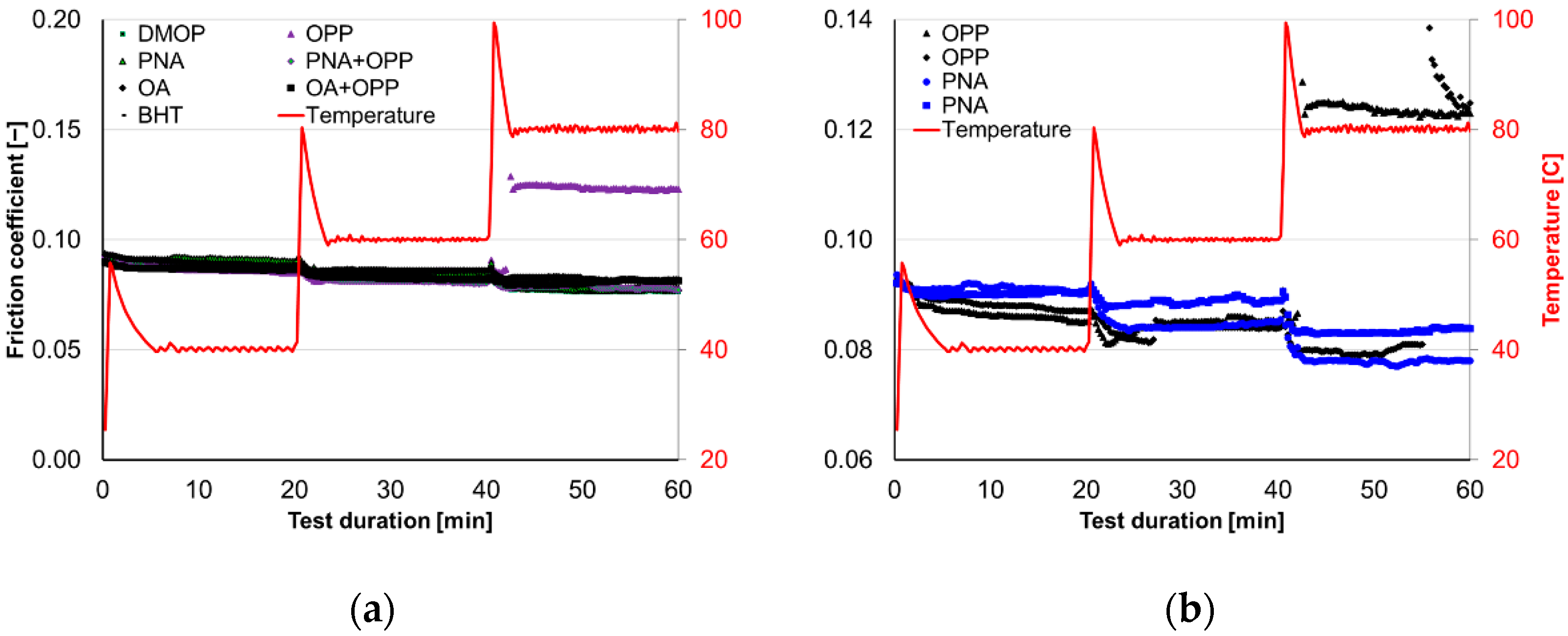
Figure 5 shows the results for three repeated tribotests with neat P-SiSO at the conditions V{300 N/40–80 °C/60 min}. As can be seen in Figure 5a, the friction trace was steady at lower temperatures (averaging 0.89 at 40 °C), which was expected considering the results presented in Figure 2. However, an abrupt change in friction characteristics was observed at the highest test temperature of 80 °C. For tests #1 and #3, a step increase in friction occurred after 50 and 55 min, respectively. From the data in Figure 5a, test #2 appeared to maintain the low friction characteristics throughout the test. However, each data point (Figure 5a) is the averaged friction coefficient over 15 s, and examining the friction trace at a higher resolution (15.4 Hz) (Figure 5b) revealed that test #2 also displayed a distinct friction spike during the final minute of the test, indicating a partial seizure. The corresponding ball wear scars are displayed in the insets of Figure 5a and the resulting wear parameters were determined as = 1.96, 1.30, and 1.97, respectively. All wear scars showed significantly different wear scar morphologies compared to previous tests where low friction was maintained throughout: these ball surfaces were clearly abraded and showed higher than average surface roughness compared to P-SiSO ball wear scars shown in Figure 2 and Figure 3. It should be noted that after the abrupt shift in friction characteristics, the friction coefficient quickly stabilized around 0.125, which indicates that the shift was not a complete loss of lubrication followed by seizure, but rather a transition to a less efficient, but seemingly stable lubrication mode.
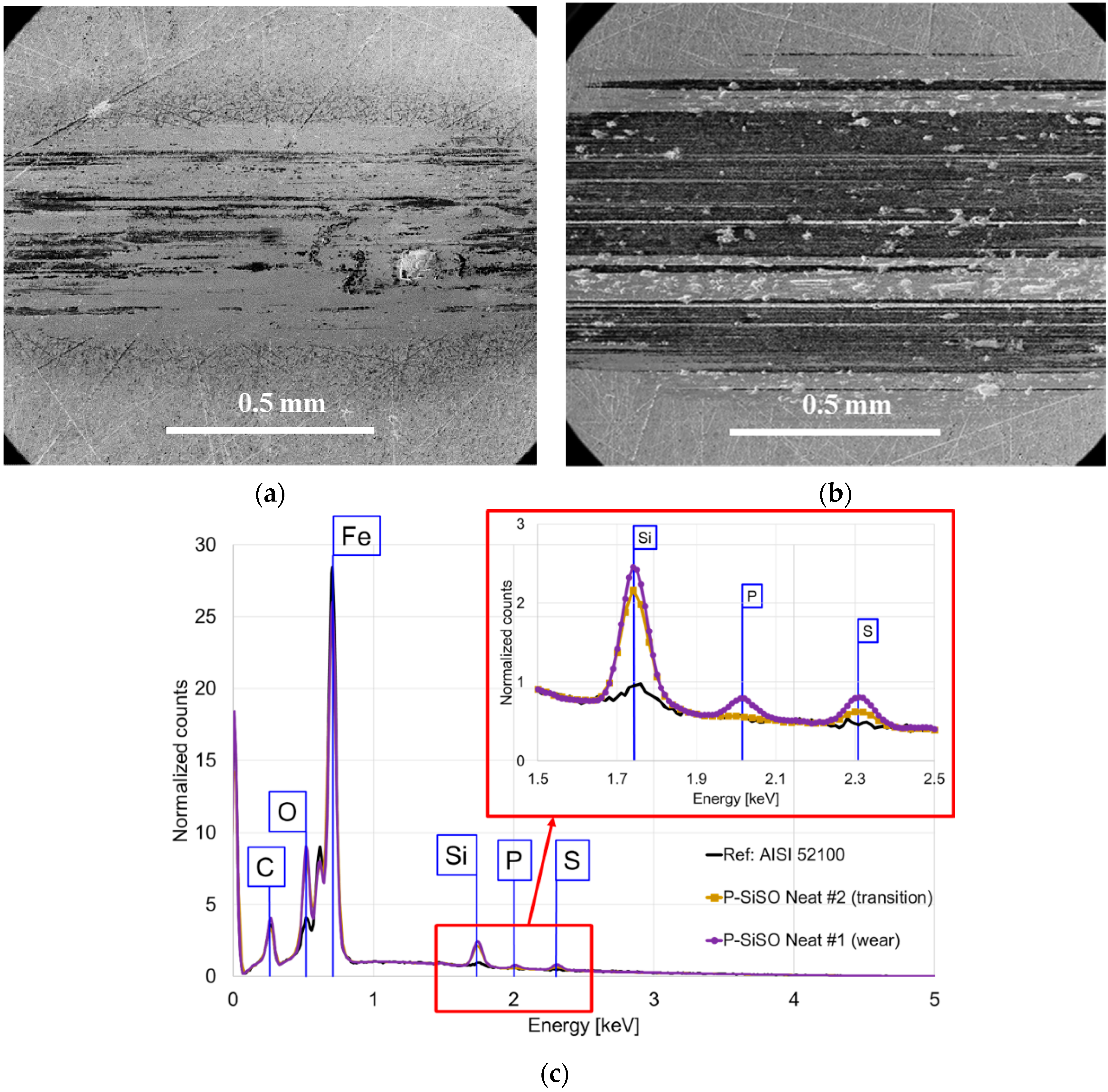
Figure 6 shows the SEM images and EDS spectra of the worn disc surfaces from the tribotest with neat P-SiSO at the conditions V{300 N/40–80 °C/60 min}. The combined SEM and EDS analysis revealed that the less worn surface, P-SiSO Neat test #2 (Figure 6a) has a composition similar to what was previously seen for the test run at V{150 N/40–100 °C/80 min}; Si and O are found in the tribofilm; and in this case also S (Figure 6c). Regarding the more severely worn sample (Figure 6b), the boundary film composition found in the disc wear scar changed and P was clearly detected, together with Si, S, O, and C (Figure 6c).
3.2. Stage 2: Effect of Additives in P-SiSO
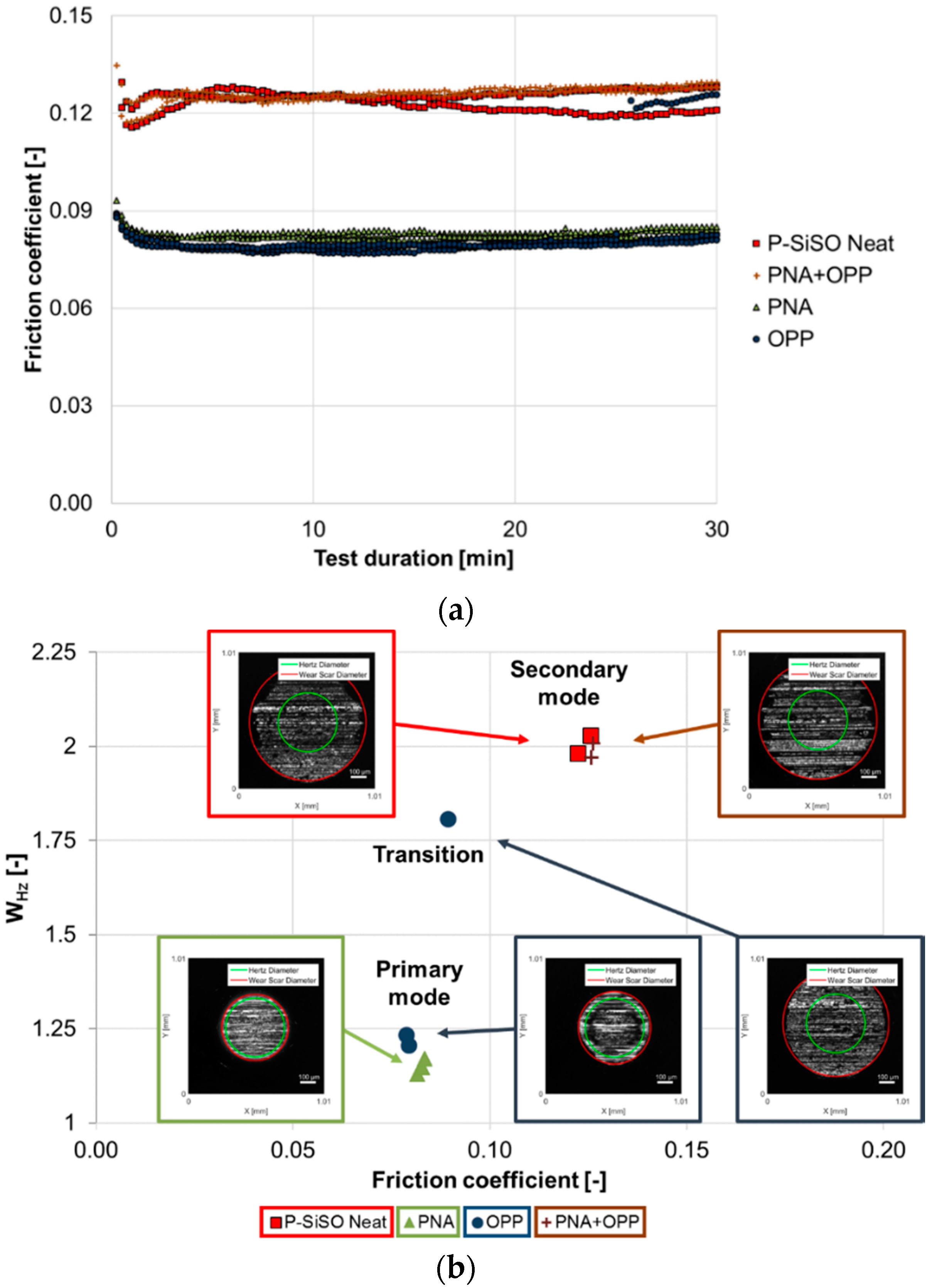
The friction traces of P-SiSO, PFPE, and the additivated P-SiSO samples evaluated at the conditions C{150 N/25 °C/30 min} are shown in Figure 7. Two repeated tests are shown for each lubricant sample. As seen in Figure 7a, the P-SiSO in neat form, as well as with all evaluated additive combinations performed significantly better than the reference PFPE in terms of friction. In Figure 7b, the vertical axis has been rescaled to focus on the additives. A trend of additive effectiveness can be discerned; the Oleylamine (OA) tends to increase friction in the two repeated tests; however, the other additives produced a slight decrease in average friction over the two repeated tests. The order of average friction coefficient is listed in the legend of Figure 7b. In Figure 7c, was plotted against the average friction coefficient. The inset figures (also found in SI) display the wear scars of the balls lubricated with neat P-SiSO, reference PFPE, and P-SiSO + PNA + OPP, which was the additive combination that produced the lowest coefficient of friction. By comparing the wear scars, it was also clear that all P-SiSO samples performed significantly better than the reference PFPE fluid in terms of wear, which was in line with our previous results using similar RTILs [24]. Although the additives appear to influence the wear scar morphology (as seen from the change in wear scar light reflection in Figure 7c), it was difficult to quantify the change in tribological performance in terms of wear with high accuracy. The reason for this is that at these conditions, the neat P-SiSO displays , which is already close to the theoretically minimum value of , as given in Equation (1), and it is therefore difficult to improve upon.
The results from the tribotests carried out at V{300 N/40–80 °C /60 min} and lubricated by the seven additivated samples are shown in Figure 8. In Figure 8a, all additives except OPP improved performance at 80 °C compared to the neat fluid. Figure 8b, shows repeated tests for best and worst performers from Figure 8a, i.e., P-SiSO with PNA or OPP. The repeated tests confirmed the poor performance of OPP and excellent performance of PNA.
The results from the harshest conditions, C{300 N/80 °C /30 min} are shown in Figure 9. As seen in Figure 9a, The neat P-SiSO generated steady friction traces around 0.125, which was similar to what could be seen after the wear mode transition of P-SiSO Neat test #1 and #3 at conditions V{300 N/40–80 °C/60 min}. Additionally, after 30 min of operating at this wear mode, , which was almost identical to the measured wear of P-SiSO Neat test #3, which only operated for 5 min at the higher wear mode. This indicates that there was a high wear related to the transitioning between these two wear modes, and that the wear rate stabilized at a low rate after the transition. The additive combination PNA + OPP was not effective at these conditions, as it performed very similarly to the neat P-SiSO. The amine PNA was expected to reduce the effect of OPP by increasing its solubility [25]. It is possible that at equimolar concentration, the neutralizing effect was too high for the additive to be effective in this test. Interestingly, OPP, which was the only additive that did not improve performance at V{300 N/40–80 °C/60 min}, performed well in two out of the three repeated tests. However, the only additive that consistently maintained low friction and wear, was PNA. As seen in Figure 9b, three repeated tests all generated low friction and . Images of all wear tracks can be found in the SI.
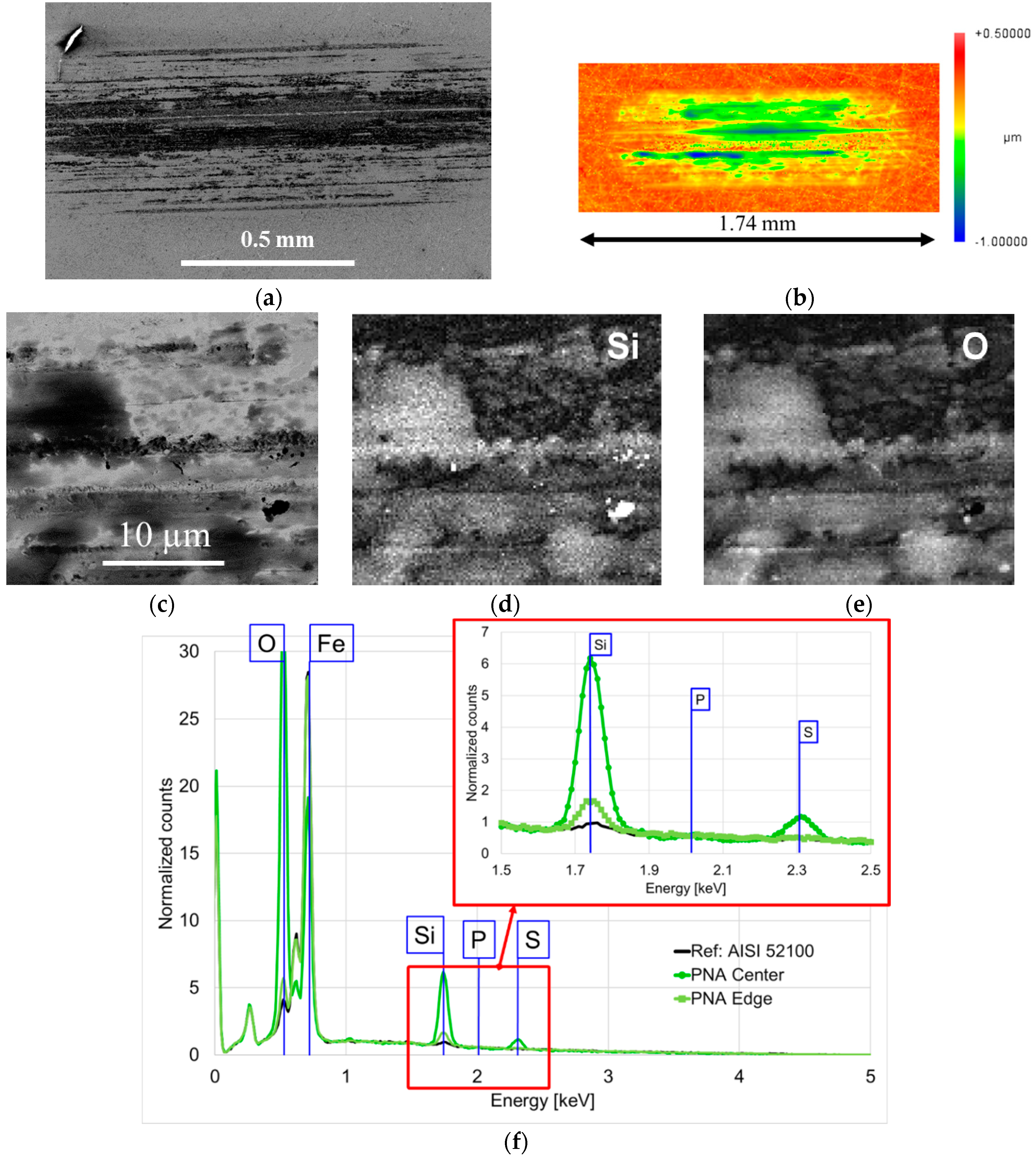
SEM images and EDS spectra of the wear track lubricated with P-SiSO + PNA added is shown in Figure 10. EDS analysis was performed on spots both in the center region and at the edge of the wear scar. In the center region of this effective boundary film, the composition was rich in the elements related to the silyl-sulfonate anion, i.e., Si, O and S. At the edge of the wear track, where the contact pressure was lower, only Si and O were found. P on the other hand, was not detected at all in this sample, and neither was N, which is an element found in PNA. Although PNA obviously affected the tribological performance in this experiment, we do not believe that it directly interacts to form the tribofilm. However, in ionic liquids, it is well-known that a change in the cation can have an effect on the ability of the anion to react and form tribofilms on the rubbed surface [13,18]. For amines such as PNA, it remains possible that it can modulate the reactivity of the base fluid P-SiSO in a similar manner. PNA is commonly used as an antioxidant [1], and in the presence of H2O it can protolyze to become a cationic species. Tentatively, it can increase the adsorption of the P-SiSO anion through an ion exchange with the phosphonium cation. The fact that the anion seems to be the major contributor to the boundary film is also in agreement with the literature on ionic liquids [11,12,13].
4. Conclusions
Based on the work reported in this paper, the following conclusions can be drawn. (1) P-SiSO forms tribologically beneficial boundary films in the conditions evaluated; (2) The elements that contributed to the boundary film in the best performing sample correspond to the elements of the anion: Si, S and O. Unexpectedly, Si and O are the most predominant; (3) P-SiSO displayed two distinct lubrication modes: initially low friction and wear, while under increasingly harsh conditions, neat P-SiSO undergoes a shift to a second lubrication mode that is characterized by a transition period of increased friction and wear, followed by lubrication at steady friction that is higher than before the shift; (4) After transitioning to the second lubrication mode (with higher friction and wear), the boundary film composition changes to include P, indicating that the cation also reacts with the surface under harsh conditions; (5) The amine type additive PNA (N-Phenyl-1-naphthylamine) successfully prevents wear and reduces friction at elevated loads and temperatures. Therefore, the additive extends the envelope of the optimum lubrication mode of P-SiSO; (6) PNA, as an additive to P-SiSO, promotes the formation of a boundary film composed of Si and O, most likely by an ion exchange that promotes the reactivity of the trimethylsilyl alkylsulfonate anion towards the steel surface.
Supplementary Materials
Supplementary materials are available online at https://www.mdpi.com/2076-3417/7/5/433/s1. Lubricant data regarding P-SiSO and PFPE. Additional tribotest results and surface analysis.
Acknowledgments
This work was funded by the “Austrian COMET-Program” in the frame of K2 XTribology (project No. 849109). The research work was carried out within the Excellence Centre of Tribology (AC2T research GmbH). The Taiho Kogyo Tribology Research Foundation (TTF) also provided funding through the 2016 15B07 grant. Erik Nyberg acknowledges funding from the Graduate School of Space Technology at Luleå University of Technology.
Author Contributions
Erik Nyberg performed most of the experiments and analysis and wrote the manuscript. Johanne Mouzon performed SEM-EDS experiments and analysis. Mattias Grahn performed analysis and interpretation of results. Ichiro Minami conceived and designed the project. All authors have given approval to the final version of the manuscript.
Conflicts of Interest
The authors declare no conflicts of interest.
Abbreviations
| RTIL | room-temperature ionic liquid |
| PFPE | perfluoropolyether |
| PNA | N-phenyl-1-naphthylamine |
| BHT | 2,6-di-tert-butyl-4-methylphenol |
| OA | oleylamine |
| DMOP | 5,5-dimethyl-1,3,2-dioxaphosphorinan-2-one |
| OPP | ortho-phenylene phosphate |
| WSD | wear scar diameter |
| HzD | hertzian contact diameter |
| EP | extreme pressure |
| AW | anti-wear |
| SEM | scanning electron microscopy |
| EDS | energy dispersive X-ray spectroscopy |
References
- Rudnick, L.R. Lubricant Additives: Chemistry and Applications; Marcel Dekker: New York, NY, USA, 2003. [Google Scholar]
- Spikes, H. The History and Mechanisms of ZDDP. Tribol. Lett. 2004, 17, 469–489. [Google Scholar] [CrossRef]
- Forbes, E.S. Antiwear and extreme pressure additives for lubricants. Tribology 1970, 3, 145–152. [Google Scholar] [CrossRef]
- Zhang, J.; Spikes, H. On the Mechanism of ZDDP Antiwear Film Formation. Tribol. Lett. 2016, 63, 1–15. [Google Scholar] [CrossRef]
- Gosvami, N.N.; Bares, J.A.; Mangolini, F.; Konicek, A.R.; Yablon, D.G.; Carpick, R.W. Mechanisms of antiwear tribofilm growth revealed in situ by single-asperity sliding contacts. Science 2015, 348, 102–106. [Google Scholar] [CrossRef] [PubMed]
- Forbes, E.S. The load-carrying action of organo-sulphur compounds—A review. Wear 1970, 15, 87–96. [Google Scholar] [CrossRef]
- Hsu, S.M.; Gates, R.S. Boundary lubricating films: Formation and lubrication mechanism. Tribol. Int. 2005, 38, 305–312. [Google Scholar] [CrossRef]
- Mortier, R.M.; Fox, M.F.; Orszulik, S.T. Chemistry and Technology of Lubricants, 3rd ed.; Springer: London, UK; New York, NY, USA; Dordrecht, The Netherlands; Heidelberg, Germany, 2010; Volume 3. [Google Scholar]
- Rudnick, L.R.; Shubkin, R.L. Synthetic Lubricants and High-performance Functional Fluids, 2nd ed.; CRC Press: New York, NY, USA, 1999; Volume 77. [Google Scholar]
- Minami, I.; Mori, S. Concept of molecular design towards additive technology for advanced lubricants. Lubr. Sci. 2007, 19, 127–149. [Google Scholar] [CrossRef]
- Bermúdez, M.D.; Jiménez, A.E.; Sanes, J.; Carrión, F.J. Ionic liquids as advanced lubricant fluids. Molecules 2009, 14, 2888–2908. [Google Scholar] [CrossRef] [PubMed]
- Minami, I. Ionic liquids in tribology. Molecules 2009, 14, 2286–2305. [Google Scholar] [CrossRef] [PubMed]
- Somers, A.E.; Howlett, P.C.; MacFarlane, D.R.; Forsyth, M. A Review of Ionic Liquid Lubricants. Lubricants 2013, 1, 3–21. [Google Scholar] [CrossRef]
- Torimoto, T.; Tsuda, T.; Okazaki, K.; Kuwabata, S. New frontiers in materials science opened by ionic liquids. Adv. Mater. 2010, 22, 1196–1221. [Google Scholar] [CrossRef] [PubMed]
- Ye, C.; Liu, W.; Chen, Y.; Yu, L. Room-temperature ionic liquids: A novel versatile lubricant. Chem. Commun. 2001, 21, 2244–2245. [Google Scholar] [CrossRef]
- Deetlefs, M.; Fanselow, M.; Seddon, K.R. Ionic liquids: The view from Mount Improbable. RSC Adv. 2016, 6, 4280–4288. [Google Scholar] [CrossRef]
- Qu, J.; Chi, M.; Meyer, H.M.; Blau, P.J.; Dai, S.; Luo, H. Nanostructure and Composition of Tribo-Boundary Films Formed in Ionic Liquid Lubrication. Tribol. Lett. 2011, 43, 205–211. [Google Scholar] [CrossRef]
- Minami, I.; Inada, T.; Sasaki, R.; Nanao, H. Tribo-Chemistry of Phosphonium-Derived Ionic Liquids. Tribol. Lett. 2010, 40, 225–235. [Google Scholar] [CrossRef]
- Kamimura, H.; Chiba, T.; Watanabe, N.; Kubo, T.; Nanao, H.; Minami, I.; Mori, S. Effects of Carboxylic Acids on Friction and Wear Reducing Properties for Alkylmethylimidazolium Derived Ionic liquids. Tribol. Online 2006, 1, 40–43. [Google Scholar] [CrossRef]
- Kamimura, H.; Kubo, T.; Minami, I.; Mori, S. Effect and mechanism of additives for ionic liquids as new lubricants. Tribol. Int. 2007, 40, 620–625. [Google Scholar] [CrossRef]
- Liu, X.; Zhou, F.; Liang, Y.; Liu, W. Benzotriazole as the additive for ionic liquid lubricant: One pathway towards actual application of ionic liquids. Tribol. Lett. 2006, 23, 191–196. [Google Scholar] [CrossRef]
- Yu, B.; Zhou, F.; Pang, C.; Wang, B.; Liang, Y.; Liu, W. Tribological evaluation of α, ω-diimidazoliumalkylene hexafluorophosphate ionic liquid and benzotriazole as additive. Tribol. Int. 2008, 41, 797–801. [Google Scholar] [CrossRef]
- Minami, I.; Watanabe, N.; Nanao, H.; Mori, S.; Fukumoto, K.; Ohno, H. Aspartic Acid-derived Wear-preventing and Friction-reducing Agents for Ionic Liquids. Chem. Lett. 2008, 37, 300–301. [Google Scholar] [CrossRef]
- Nyberg, E.; Respatiningsih, C.Y.; Minami, I. Molecular design of advanced lubricant base fluids: Hydrocarbon-mimicking ionic liquids. RSC Adv. 2017, 7, 6364–6373. [Google Scholar] [CrossRef]
- Minami, I.; Kikuta, S.; Okabe, H. Anti-wear and friction reducing additives composed of ortho-phenylene phosphate-amine salts for polyether type base stocks. Tribol. Int. 1998, 31, 305–312. [Google Scholar] [CrossRef]
- Wang, Q.J.; Zhu, D. Hertz Theory: Contact of Ellipsoidal Surfaces. In Encyclopedia of Tribology; Wang, Q.J., Chung, Y.-W., Eds.; Springer: Boston, MA, USA, 2013; pp. 1647–1654. [Google Scholar]
- Kalin, M.; Vižintin, J. Use of equations for wear volume determination in fretting experiments. Wear 2000, 237, 39–48. [Google Scholar] [CrossRef]
- Sakamoto, T.; Uetz, H.; Föhl, J.; Khosrawi, M.A. The reaction layer formed on steel by additives based on sulphur and phosphorus compounds under conditions of boundary lubrication. Wear 1982, 77, 139–157. [Google Scholar] [CrossRef]
- Zhu, L.; Chen, L.; Yang, X.; Song, H. Functionalized Ionic Liquids as Lubricants for Steel-Steel Contact. Appl. Mech. Mater. 2012, 138, 630–634. [Google Scholar] [CrossRef]
- Jiang, D.; Hu, L.; Feng, D. Crown-type ionic liquids as lubricants for steel-on-steel system. Tribol. Lett. 2011, 41, 417–424. [Google Scholar] [CrossRef]
- Liu, X.; Zhou, F.; Liang, Y.; Liu, W. Tribological performance of phosphonium based ionic liquids for an aluminum-on-steel system and opinions on lubrication mechanism. Wear 2006, 261, 1174–1179. [Google Scholar] [CrossRef]
- Weng, L.J.; Liu, X.Q.; Liang, Y.M.; Xue, Q.J. Effect of tetraalkylphosphonium based ionic liquids as lubricants on the tribological performance of a steel-on-steel system. Tribol. Lett. 2007, 26, 11–17. [Google Scholar] [CrossRef]
- Mu, Z.; Zhou, F.; Zhang, S.; Liang, Y.; Liu, W. Effect of the functional groups in ionic liquid molecules on the friction and wear behavior of aluminum alloy in lubricated aluminum-on-steel contact. Tribol. Int. 2005, 38, 725–731. [Google Scholar] [CrossRef]
Figure 1.
Chemical structures of evaluated ionic liquid base fluid and additives.

Figure 2.
Results from tribotests at conditions V{100–300 N/25 °C/120 min}. The friction traces are shown for two repeated tests with neat P-SiSO, compared to one test with PFPE and one test of GL-5. The wear scars corresponding to the friction traces are shown as color-coded insets in the right part of the figure.

Figure 3.
Results of V{150 N/40–100 °C/80 min} for two repeated tests with neat P-SiSO. Ball wear scars are shown as insets to the right.
Figure 3.
Results of V{150 N/40–100 °C/80 min} for two repeated tests with neat P-SiSO. Ball wear scars are shown as insets to the right.

Figure 4.
Disc surface after tribotesting at V{150 N/40–100 °C/80 min}, seen from (a) optical profilometer; and (b) SEM. (a) the roughness inside wear scar can be seen to be of the same order of magnitude as the original lapped surface; (b) dark patches in the wear track indicate tribofilm; (c) SEM (scanning electron microscopy) image of a representative area of tribofilm at 5000x magnification; (d,e) EDS (energy dispersive X-ray spectroscopy) maps showing the distribution of the elements in the area shown in (c).
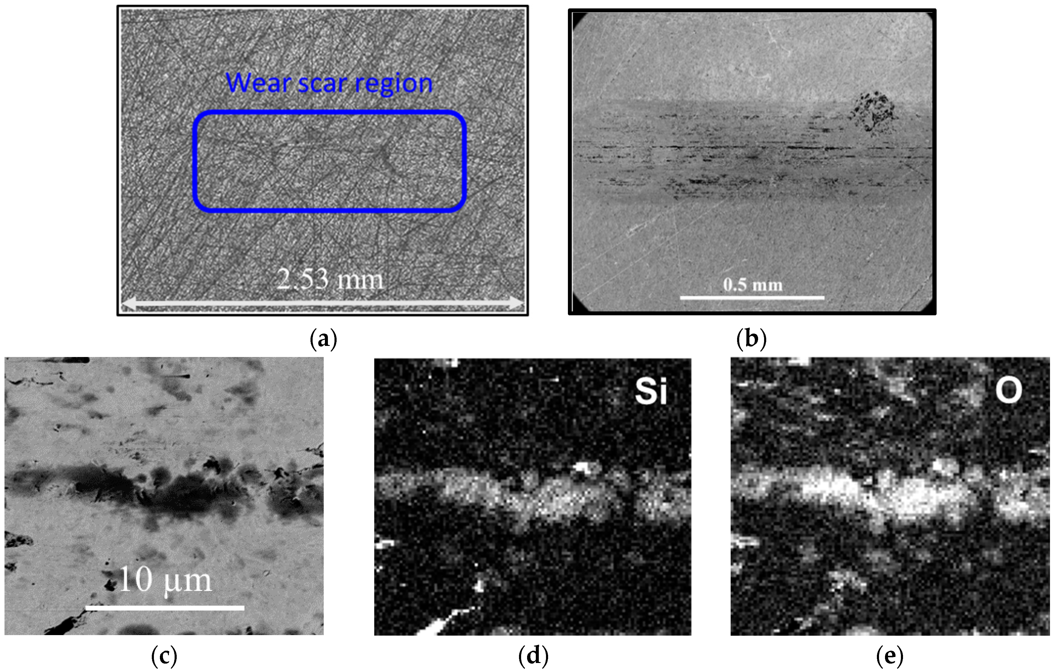
Figure 5.
Results from V{300 N/40–80 °C /60 min}. (a) Three repeated tests with neat P-SiSO, where test #2 appears to pass the 80 °C level without step increase in friction; (b) higher resolution data examined for test #2 in (a) revealed that test #2 also displayed step increases in friction. Insets display ball wear scars corresponding to tests #1–3, respectively.
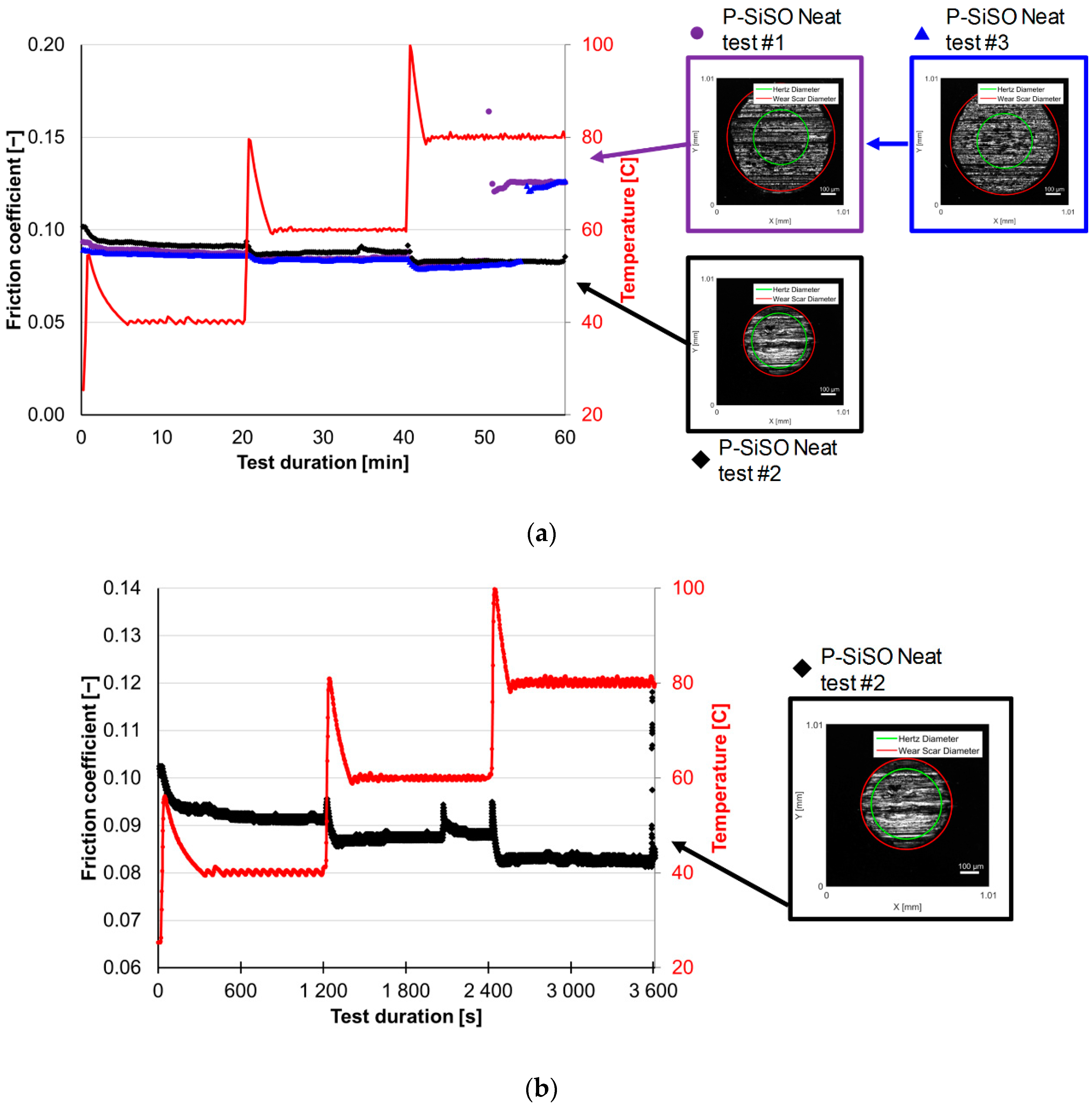
Figure 6.
Analysis of disc surfaces from V{300 N/40–80 °C /60 min}. (a) and (b) display SEM images showing the tribofilms on the wear tracks for tests #2 and #1 respectively. (c) EDS spectra of representative regions of the wear scars shown in (a) and (b).
Figure 6.
Analysis of disc surfaces from V{300 N/40–80 °C /60 min}. (a) and (b) display SEM images showing the tribofilms on the wear tracks for tests #2 and #1 respectively. (c) EDS spectra of representative regions of the wear scars shown in (a) and (b).

Figure 7.
Results from the experiments at C{150 N/25 °C /30 min}. (a) Friction traces for the reference PFPE and P-SiSO with and without additives; (b) magnified friction traces of P-SiSO with and without additives; and (c) µ-W chart with insets of ball wear scars for PFPE, neat P-SiSO and P-SiSO with PNA + OPP additives, respectively.
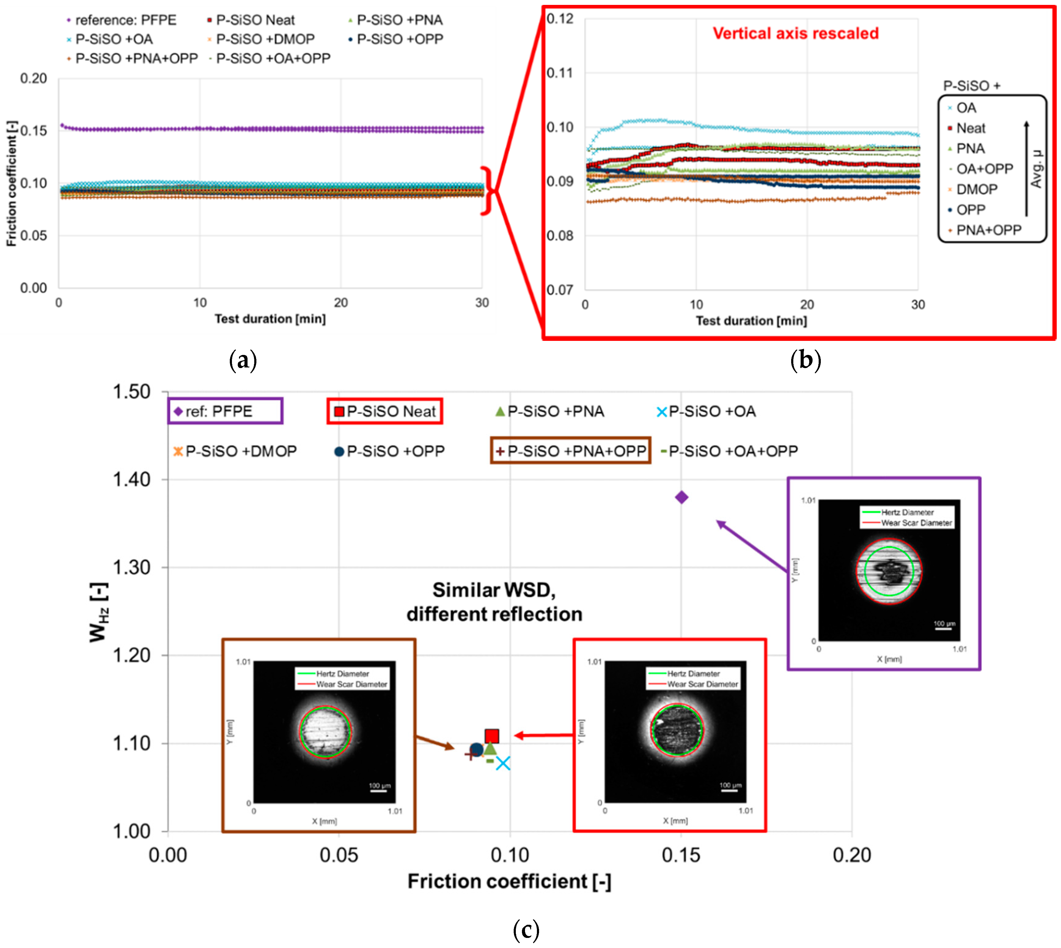
Figure 8.
Results from the V{300 N/40–80 °C /60 min} tests. (a) Different additives in P-SiSO; and (b) repeated tests of best and worst performers.
Figure 8.
Results from the V{300 N/40–80 °C /60 min} tests. (a) Different additives in P-SiSO; and (b) repeated tests of best and worst performers.

Figure 9.
Results from the experiments at C{300 N/80 °C/30 min}. (a) Friction traces of Neat P-SiSO compared to P-SiSO with additives N-Phenyl-1-naphthylamine (PNA), Ortho-phenylene phosphate (OPP), and PNA + OPP. (b) Corresponding µ-W chart with insets of ball wear scars.
Figure 9.
Results from the experiments at C{300 N/80 °C/30 min}. (a) Friction traces of Neat P-SiSO compared to P-SiSO with additives N-Phenyl-1-naphthylamine (PNA), Ortho-phenylene phosphate (OPP), and PNA + OPP. (b) Corresponding µ-W chart with insets of ball wear scars.

Figure 10.
Surface analysis of disc wear scar lubricated with P-SiSO + PNA at conditions V{300 N/40–80 °C/60 min}. (a) SEM image showing the tribofilm on the wear track; (b) wear scars are mild with peak-to-valley around 2 µm; and (c) SEM image of a representative area of tribofilm at 5000× magnification; (d,e) EDS maps showing the distribution of the elements in the area shown in (c); (f) EDS-spectra comparing the composition of the tribofilm between the center and edge of the wear track.


Table 1.
Test codes describing conditions (load, temperature, duration) corresponding to the different tribotest stages.
Table 1.
Test codes describing conditions (load, temperature, duration) corresponding to the different tribotest stages.
| Test Stage and Objective | Test Code |
|---|---|
| Stage 1: Determine limit of operational envelope of neat P-SiSO | V{100–300 N/25 °C/120 min} |
| V{150 N/40–100 °C/80 min} | |
| V{300 N/40–80 °C/60 min} | |
| Stage 2: Determine effect of additives in P-SiSO | C{150 N/25 °C/30 min} |
| V{300 N/40–80 °C/60 min} | |
| C{300 N/80 °C/30 min} |
© 2017 by the authors. Licensee MDPI, Basel, Switzerland. This article is an open access article distributed under the terms and conditions of the Creative Commons Attribution (CC BY) license (http://creativecommons.org/licenses/by/4.0/).
Share and Cite
MDPI and ACS Style
Nyberg, E.; Mouzon, J.; Grahn, M.; Minami, I. Formation of Boundary Film from Ionic Liquids Enhanced by Additives. Appl. Sci. 2017, 7, 433. https://doi.org/10.3390/app7050433
AMA Style
Nyberg E, Mouzon J, Grahn M, Minami I. Formation of Boundary Film from Ionic Liquids Enhanced by Additives. Applied Sciences. 2017; 7(5):433. https://doi.org/10.3390/app7050433
Chicago/Turabian StyleNyberg, Erik, Johanne Mouzon, Mattias Grahn, and Ichiro Minami. 2017. "Formation of Boundary Film from Ionic Liquids Enhanced by Additives" Applied Sciences 7, no. 5: 433. https://doi.org/10.3390/app7050433
Note that from the first issue of 2016, this journal uses article numbers instead of page numbers. See further details here.