
A Key Management Scheme for Mobile Wireless Sensor Networks


Dipartimento di Automatica e Informatica, Politecnico di Torino, 10129 Torino, Italy
*
Author to whom correspondence should be addressed.
Appl. Sci. 2017, 7(5), 490; https://doi.org/10.3390/app7050490
Submission received: 29 March 2017
/
Revised: 4 May 2017
/
Accepted: 5 May 2017
/
Published: 10 May 2017
Abstract
:Symmetric encryption is the most commonly employed security solution in wireless sensor networks (WSNs). In this paper, a new approach that employs public-key cryptography during key establishment is proposed. In a WSN, the main issue for public-key cryptography is represented by communication and computational overheads. In order to reduce these requirements, a new authentication system based on authentication tables is proposed. An analytical study shows that the proposed approach provided optimal protection against an adversary that compromised one or more nodes. A comparative analysis shows that, according to the dimension and the density of the network, the proposed approach can represent the best solution. Furthermore, an experimental analysis conducted on a real network shows that the proposed approach can be successfully applied to devices with limited computational power.
1. Introduction
Wireless sensor networks (WSNs) are a widely employed type of ubiquitous technology. They are usually composed of low cost devices with limited communication and computational resources, and with a small memory. Although the majority of WSNs are composed of homogeneous devices, often the device that acts as a gateway (sink) has larger resources. WSNs are used for many applications, such as smart cities [1], health-care [2], industrial automation [3], smart transport systems [4] and food control [5]. Since WSNs have limited capabilities, they adopt specific solutions instead of standard network protocols (e.g., message authentication code (MAC) [6], routing [7,8], and deployment strategies [9]). Although some WSNs use public-key cryptography [10], security is normally based on symmetric-key cryptography [11]. Therefore, two nodes within the reciprocal communication range must share a key in order to communicate. The establishment of symmetric keys is called key management. Although there are techniques for the detection of compromised nodes and for the recovery of security [12,13], key management significantly affects the performance and the level of security of the network. Moreover, WSNs have drastically different characteristics, so there exist many valid key management schemes that can be applied to different kinds of networks.
Two basic approaches [14] for the establishment of secret keys in WSNs are:
- Plain global key (PGK), where a unique key is used in the network;
- Full pairwise keys (FPWK), where a specific key is shared by each possible couple of nodes.
Since in these approaches all keys are predistributed before the deployment, the nodes do not execute any additional operation for the key establishment. Moreover, they do not require special information (e.g., deployment knowledge). The PGK approach involves a limited memory overhead, but it provides a poor level of security, since an opponent that steals a key is able to eavesdrop on all links of the network and produce fake nodes. The FPWK approach provides a better level of security, since a key can only be used to eavesdrop on a unique link. However, each node stores a number of keys equal to the quantity of nodes in the network, so a large memory area is required. Therefore, both schemes have relevant drawbacks: the PGK scheme has a poor level of security, while the FPWK approach is only compliant with small networks.
WSNs have different characteristics that affect the security and allow or require specific key management solutions (e.g., heterogeneous nodes [15] and deployment knowledge [16]). However, many key management schemes have been proposed with the aim to increase the level of security of generic homogeneous WSNs, even exploiting public-key cryptography. The basic approach based on public-key cryptography has been proposed in [17]. It employs digital certificates, used for the authentication of the identification number and of the public key of a node. In a WSN, digital certificates correspond to a signature generated by the administrator of the network. This approach, like that of FPWK, provides a high protection against an adversary that has compromised some nodes. However, it requires more computational and communication resources than symmetric encryption.
In order to reduce the overhead introduced by public-key cryptography without reducing the level of security, a new authentication mechanism is proposed. The novel scheme, called public-key cryptography with authentication table key management scheme (PCAT), is suitable for mobile and static WSNs. The privacy of messages used for the establishment of symmetric pairwise keys is guaranteed by public-key cryptography. Similarly to FPWK, in the proposed scheme each node stores a table with an entry for every other node in the WSN. An identification mechanism allows the authentication of valid nodes by cheeking their public keys and identification numbers. This mechanism avoids the introduction of fake nodes, since an opponent cannot have a valid secret key. The required memory is proportional to the size of the network. However, with respect to FPWK, the information required to authenticate a node is smaller. Therefore, PCAT can be applied with larger networks than FPWK. Moreover, the use of authentication tables allows for transmitting less information and computing fewer cryptographic operations with respect to digital certificates, which represent the state-of-the-art for the public-key cryptography.
A theoretical evaluation and a comparison with the state-of-the-art shows that PCAT provides an optimal level of security in terms of resilience against an adversary that has compromised at least one node. Moreover, an experimental evaluation, based on the implementation of the protocol on a WSN, demonstrates the feasibility of the proposed approach. The public-key encryption technique used for the implementation of the protocol is elliptic curve cryptography (ECC) [18].
The organization of the rest of the paper is as follows: in Section 2 related works are described. In Section 3 PCAT is detailed. In Section 4, a comparative analysis is presented. Finally in Section 5 a prototype is implemented and tested on real nodes, while in Section 6 some conclusions are drawn.
2. Related Work
Much research in recent years has focused on key management for WSNs [14]. This section describes the most relevant schemes. The main characteristics of the protocols, including the possibility of adding nodes to the network and the compatibility with mobile networks, will be discussed.
2.1. Public-Key Cryptography
The main key management approach that employs public-key cryptography is based on the Secure Sockets Layer (SSL) handshake (The SSL Protocol Version 3.0. https://tools.ietf.org/html/rfc6101). An implementation has been analyzed in [17]. In this approach, each node owns a couple of public and secret keys. Moreover, each node owns a certificate that guarantees its authenticity and the public key of the administrator. The certificate is composed of the public key of the node, its identification number, and a signature computed by the administrator with its secret key. Any node can verify the authenticity of a certificate and can encrypt the messages used for the handshake with the public key of the other node. The main problem of this approach is represented by the computational and communication overheads. Each node must encrypt and decrypt a message and verify the signature of the certificate. Moreover, each node must send to the other their certificate and an encrypted message. For the sake of simplicity, in the following the described approach is called SSL.
Public-key cryptography has been also successfully used for specific tasks or contexts. In [19], the authors present a key-management scheme based on ECC for hierarchical networks with heterogeneous nodes. In [10,20], the authors propose two acceleration mechanisms for public-key signature verification in broadcast authentication.
2.2. Random Key Distribution
In the schemes based on random key distribution, a node stores a ring of r starting keys. The rings are randomly picked from a larger pool of p starting keys. A couple of nodes can only communicate if they share a starting key. If an adversary compromises a node, he/she only obtains a part of the starting keys used in the network. The drawbacks due to a compromised node are limited. However, the connectivity in the network is reduced, since two nodes may not share any common key and be unable to communicate. Schemes based on the random key distribution can be applied both to mobile and to static networks. This kind of approach has been extended even to vehicular ad hoc networks [21].
In [22], Eschenauer and Gligor presented an approach hereafter called EG . Before deployment, a pool of p keys is produced and, for each node, a ring of r keys is randomly selected from the pool and distributed to that node. After deployment, every node verifies if it shares keys with the nodes within its communication range. The configuration of p and r affects the performance of the network. If the magnitude of r and of p is close, the nodes can establish common keys with the majority of the other nodes. However, if a node is compromised, a large part of the WSN is also compromised. If r is too small with respect to p, the nodes cannot communicate with all the nodes in their communication range, but an adversary that has compromised a node can achieve a low percentage of pairwise keys.
An evolution of EG is q-composite random key predistribution [23]. With this scheme, a link between a pair of nodes can be established only if they have at least q shared keys. Their pairwise key is computed by a hash function executed on the concatenation of the shared keys. In case of a small quantity of captured nodes, the q-composite approach provides a higher level of security than EG. However, EG is less vulnerable when several nodes have been compromised. According to the analysis proposed in [23], q is set to 2. In the following, q-composite is called 2C.
In [24], the authors propose q-s-Composite, a further evolution of EG and q-composite. In this scheme there are a minimum (q) and a maximum (s) quantity of initial keys used to establishment a pairwise key. A new organization of the storage allows to increase the quantity of initial keys per node with the same memory overhead. According to the analysis proposed in [24], q is set to 1 and s to 5. In the following, the q-s-Composite is called 1–5C.
2.3. Global Master Key
This technique employs a master key (MK) to generate the pairwise keys of the network. Symmetric-key key establishment (SKKE), used by ZigBee (ZigBee Specification, Document 053474r20, September 2012, ZigBee Alliance), employs an MK that is known by every node. In the establishment of a pair-wise key, a node A sends its identifier ID and a random number C. Node B receives the message and sends to A its identifier ID, a new random number C and the MAC that is calculated on a constant number , ID, ID, C and C. Both nodes execute a keyed hash function with MK as a key on ID and ID concatenated to C and C in order to generate a common secret. Then, a hash function on the common secret is used to compute two keys: MAC key to authenticate the messages and KeyData to protect the link. Then, node A checks the MAC and sends to node B a MAC calculated on a second constant number concatenated to the same data used for the first MAC.
SKKE can be applied to mobile and static wireless networks. The memory occupied by the keys is small. However, if MK is compromised, SKKE provides a low level of security, since an opponent could generate every key, if he/she had eavesdropped on the messages that were used to the generate the key.
2.4. Transitory Master Key
The group of schemes based on a transitory master key employs MK to generate the pairwise keys among the nodes. MK is deleted by every node after a timeout. The security in this approach is founded on the assumption that a node cannot be compromised before a lower bound of time. Therefore, before this time each node should delete MK.
The first period of activity of a node after its deployment is called the initialization phase. After a timeout, a node moves to the working phase. In a basic version, the nodes in the working phase cannot establish new keys. However, some approaches allow nodes in the initialization phase to establish keys with nodes in the working phase. This mechanism allows new nodes to be added into the network.
If the initialization phase is particularly long, the probability that an opponent can compromise the MK grows. However, by reducing the timeout, even the quantity of keys that a node can establish becomes lower. Therefore, a shorter timeout reduces the connectivity of the WSN. If an adversary compromises MK, he/she can decrypt all the messages eavesdropped during the initialization phase, potentially compromising all the pairwise keys in the network. Moreover, if the key management scheme allows the addition of nodes to the networks after the first deployment, the opponent can establish a pairwise key with every new node.
Localized encryption and authentication protocol plus (LEAP+) [25] is a well-known transitory master key scheme. During the initialization, all the nodes know a pseudo-random function and MK. All nodes have their own private master key (PMK), computed with the pseudo-random function by using the identifier of the node as a seed and MK as a key. Within the initialization phase, each pair of nodes generate the pairwise keys with the pseudo-random function by using the identifier of the second node as a seed and PMK of the first node as a key. The nodes added after the initial deployment use MK to compute the PMKs of the nodes in its communication range. With this secret they can generate a common keys. After a timeout period, each node erases all keys used to compute the final pairwise keys with the exception of their PMK, that will be used in case of possible future added nodes.
LEAP+ can be applied only to static wireless networks.
In [26], the authors propose Fast LEAP+ (FLEAP) a new transitory master key scheme with a faster key establishment phase. The handshake is split in separated sub-phases in order to anticipate the deletion of the master secrets.
In[27], Random seed distribution with transitory master key (RSDTMK) is proposed. This protocol distributes transitory master secrets before deployment. The nodes need shared secrets in order to establish pairwise keys and the secrets are deleted after a timeout.
3. Public-Key Cryptography with an Authentication Table Key Management Scheme (PCAT)
The proposed key management scheme is based on public-key cryptography. Asymmetric encryption is used to protect the privacy of the messages exchanged during the key establishment. Each node holds a pair of public and secret keys. Public-key cryptography provides secure communications without the predistribution of shared secret material. Thus, an opponent that compromises a node will not obtain any useful information about the rest of the network. However, an additional authentication mechanism is required in order to recognize the eligible nodes. In PCAT, each node stores an authentication table composed of a row for every other node in the network. Each row contains the information required to authenticate a node.
3.1. Notation and Assumption
The notations used in the analysis of PCAT include:
- total number of nodes (n);
- quantity of bits indexed by the mask (m);
- length of the public key ();
- length of the private key ();
- length of the hash codes ().
- quantity of nodes within the communication range of node i ().
It is assumed that the WSN is composed of homogeneous mobile nodes and that there is no deployment knowledge. It is also assumed that an opponent is able to inject packets, replay older messages, eavesdrop on all the traffic and compromise a node with all the information it holds.
3.2. Predeployment Phase
Before deploying the WSN, the administrator of the network sets the parameters of PCAT (i.e., m and ), extracts the random numbers (i.e., the m indexes in the masks), generates the cryptographic material (i.e., the public and secret keys), computes the authentication tables, and distributes to each node the proper data. Each node knows a public cryptosystem, a symmetric cryptosystem and a hash function. Moreover, each node i is set up with the following unique data:
- a node identifier (ID),
- a couple of public (Puk) and secret (Prk) keys,
- a bit mask (Mask), corresponding to a list of m indexes of bits inside the public keys,
- an authentication table for the authentication of the other nodes.
The authentication table stores the information required by a node to authenticate any other node of the network. Each row of the authentication table corresponds to another node of the WSN. For each row two entries are generated starting from the public key of the node corresponding to that row. The bits indexed by the mask are directly copied into the table. On the remaining bits, a hash function H() is executed and its result is stored in the same row.
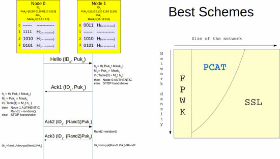
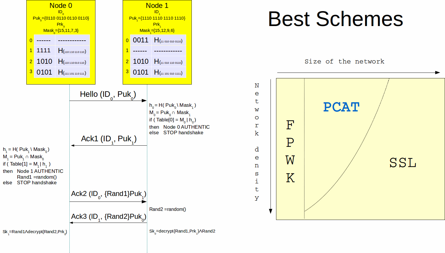
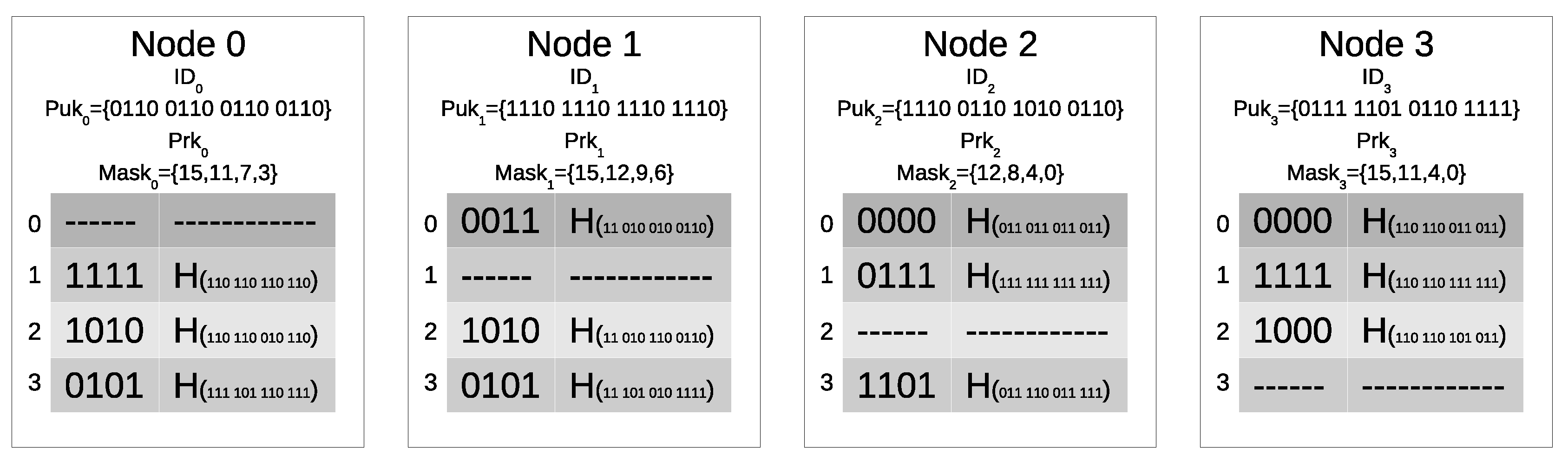
Figure 1 shows an example of the data stored by the nodes. In the example, the mask stores 4 values and the length of the public key is 16 bits. The m indexes in the mask of Node 0 are 15, 11, 7 and 3. Since the first index is 15, the first bit of each row is equal to the bit with index 15, i.e., the most significant one, in the corresponding Puk: 1 for row 1, 1 for row 2, and 0 for row 2. In the same manner, since the second index is 11, the second bit of each row is equal to the bit at index 11 in the corresponding Puk. The described method is used to fill in the first field of all the rows in each table.
In the authentication table, the second field of each row corresponds to a hash function executed on the bits that are not included in the first field of the row. For example, considering row 0 of the authentication table of Node 1, the bits corresponding to the indexes in the mask of Node 1 (15,12,9,6, in bold) are extracted from the 16 bits of Puk (0110 0110 0110 0110), and stored in the first field of the row, while the result of a hash function computed on the other bits is stored in the second field of the row.
3.3. Key Establishment
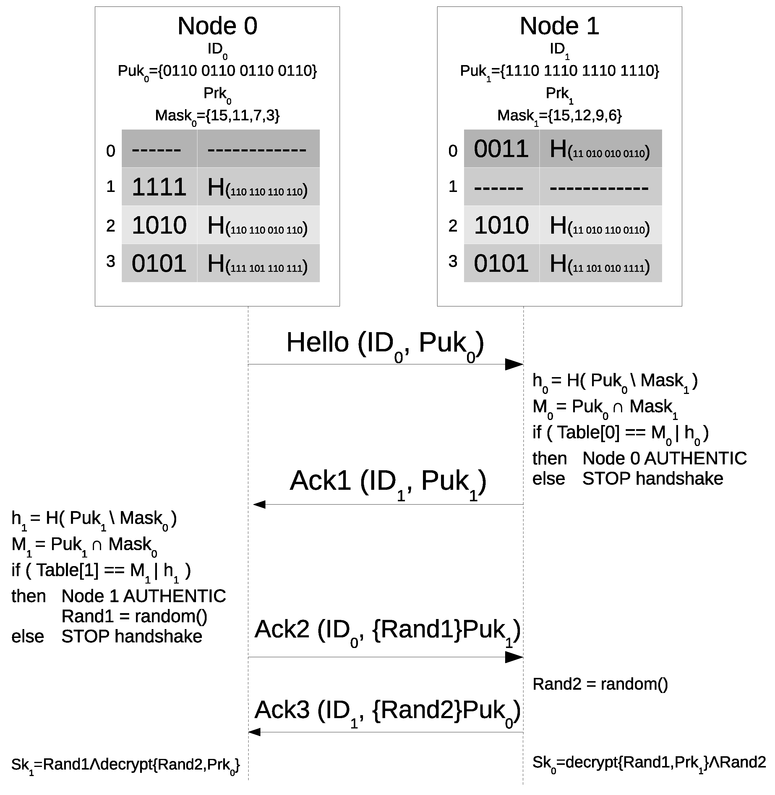
Figure 2 shows the pairwise key establishment. In the example, node 0 is the initiator of the key establishment with node 1, which plays the role of the responder. All nodes periodically broadcast a Hello message. The Hello holds the identifier of the node and its public key. In the example, Node 0 starts the handshake by broadcasting ID and Puk.
When a node receives a Hello from a node without a common pairwise key, it executes an authentication check. The authentication check is composed of two steps. For the former, the responder searches inside the received public key for the bits pointed by the addresses in its mask. The first test is passed if these bits correspond to the ones stored in the row of the authentication table related to the initiator. For the latter, the responder executes the hash function on the bits of the public key that are not pointed out by the mask. If the resulting hash also corresponds to the hash stored in the same row of the table, the initiator is considered authentic. In the example, after receiving the Hello, Node 1 checks if the four bits (M) in Puk at the addresses written in its mask (15, 12, 9, 6) correspond to the four bits in the first row of its table. Then, Node 1 executes the hash (h) on the other bits of Puk, by excluding bits 15, 12, 9 and 6, and checks if the result is equal to the content of the second part of row 0 in its identification table. If the Hello passes the authentication check, the responder sends a first acknowledge message (Ack1) to the initiator of the handshake. This message stores the identification of the second node and its public key. In the example, Node 1 sends ID and Puk to Node 0.
After receiving an Ack1, the initiator checks its authenticity. In the example, after receiving the Ack1, Node 0 checks if the four bits in Puk at the addresses written in its mask (15, 11, 7, 3) correspond to the four bits (M) in the first row of its table. Then, Node 0 executes the hash (h) on the other bits of Puk, by excluding bits 15, 11, 7 and 3, and checks if the result is equal to the content of the second part of row 1 in its identification table.
If the Ack1 message is authentic, the initiator calculates a random number that will be used for the generation of the pairwise key. The required length of the random number is equal to the pairwise key. However, in order to avoid security risks due to the encryption of a short plaintext, eventual additional random bits are added to exploit the whole input of the encryption. The initiator answers with a second acknowledge message (Ack2) that contains the random number encrypted with the public key of the responder. In the example, after computing a first random number (Rand1), Node 0 encrypts it by using Puk and sends a message to Node 1 that contains ID and the encrypted Rand1.
After receiving an Ack2 from a node that has already passed the authentication check, the responder calculates a random number and sends to the initiator an Ack3 message, that contains this number encrypted with the public key of the initiator. Then, both the nodes decrypt the received number and compute a symmetric pairwise key that corresponds to the bitwise XOR of the two random numbers.
After receiving the Ack2, also Node 1 computes a second random number (Rand2), encrypts it by using Puk and sends ID and the encrypted Rand2 to Node 0. Finally, both the nodes decrypt the received random number by using their Prk and compute the pairwise key (Sk = Sk) by executing a bitwise XOR operation on Rand1 and Rand2.
3.4. Node Adding
In the proposed scheme, the nodes store the information required to identify other nodes for all the time in which they are active. Therefore, PCAT is compliant with mobile networks and it is able to manage the insertion of new nodes into the network after the first deployment. However, for each new node added to the network after the initial deployment, a specific row in the authentication table is required, so the size of the table imposes an upper bound to the total quantity of nodes.
Before the deployment, the administrator of the network generates the data for the maximum number of nodes compliant with the selected dimension of the authentication tables, even if the quantity of initial nodes is lower. All the tables also include the rows not matched to the initial nodes. A node added to the network after the initial deployment is set up with a packet of still available data, i.e., ID, keys, bit mask and authentication table. The new node executes the normal handshake routine.
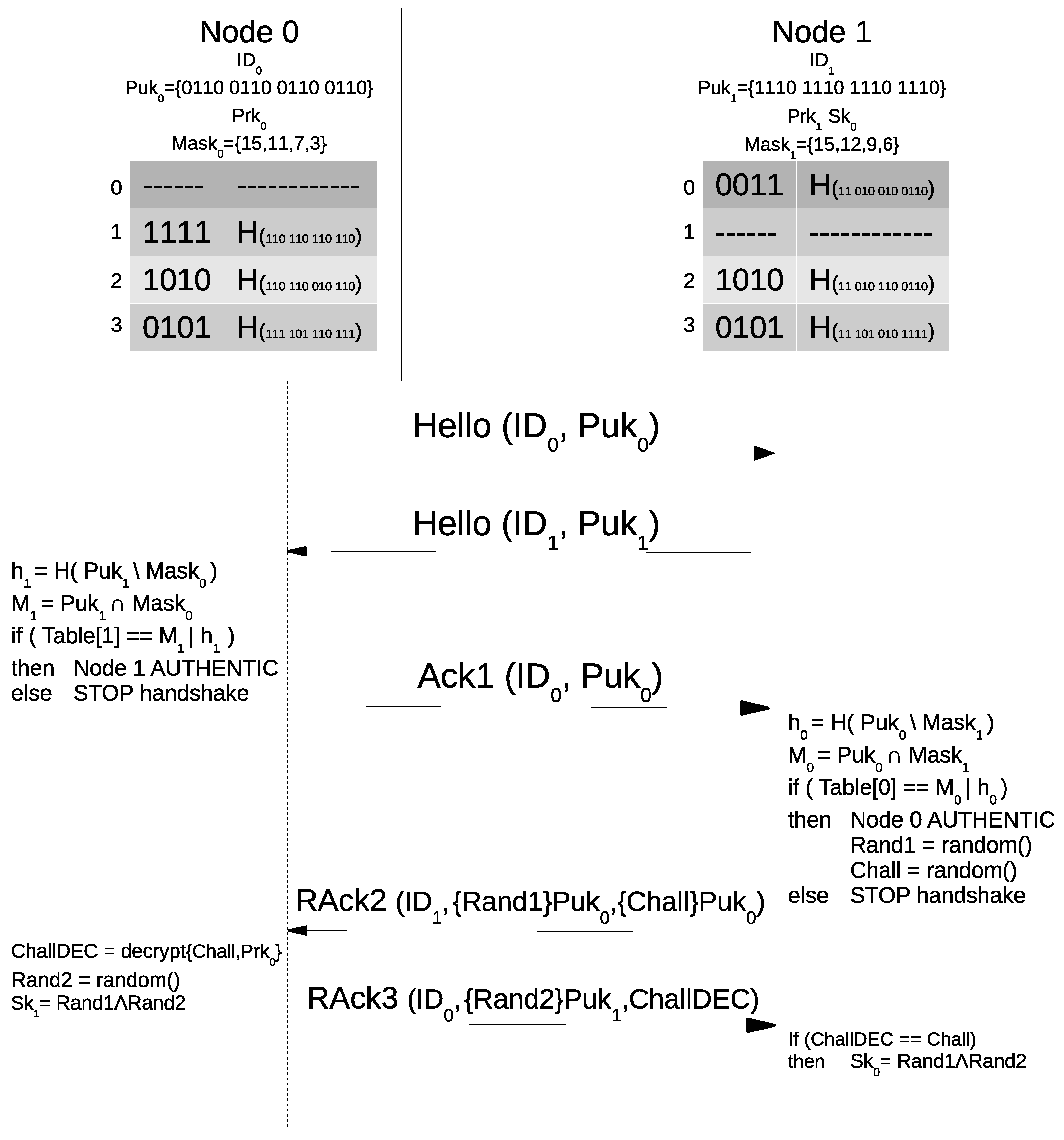
A node that was removed from the network because of a failure or low battery is reintroduced in the network without changing its memory. Thus, it is still able to continue its previous tasks. However, if the node must be changed, a new node with the same initial security information can be deployed. The new node will execute the routine described in Figure 3. The nodes that already share a pairwise key with a reintroduced node do not answer its Hello messages. However, the new node does not share a pairwise key with them, so it answers with an Ack1 message to their Hello messages. When a node receives an Ack1 message from a node already matched to a pairwise key, it checks the authenticity of the credentials, and then sends back a reintroduced second acknowledge message (RAck2), in order to check if the node is authentic and to establish a new key. In contrast to Ack2 messages, an RAck2 also contains a random challenge (Chall) encrypted with the public key of the new node. The new node answers with a reintroduced third acknowledge message (RAck3), which includes the same data of an Ack3 message and the decrypted random challenge (ChallDEC). The verification of the challenge demonstrates that the new node is authentic and that it needs a new pairwise key.
4. Evaluation and Comparison
This section analyzes PCAT and compares it with respect to the state-of-the-art schemes. The comparison considers the peculiarities of the approaches. Some protocols allow the generation of various kinds of keys (e.g., local broadcast keys). Normally the establishment of these additional keys is based on the pairwise key establishment, and it can be applied to different schemes. This layer is compliant with the majority of the schemes, but normally it is not included in the description. Moreover, some schemes generate two pairwise keys to manage both encryption and signature. The presence of a pair of keys is useful for the majority of the schemes, but it is often not included in the analysis of the approaches. Therefore, in order to reach a fair comparison the following analysis is focused on the establishment of one symmetric pairwise key per link.
4.1. Attacker Model
An adversary knows all the cryptographic primitives, the and the public keys of all the nodes. However, he/she does not know the secret keys. With any scheme, after compromising a node, the adversary is able to use that node like it would be authentic. Moreover, the adversary can replay messages and inject new ones.
An opponent is able to compromise a node, and achieve the data stored in its memory. By using PCAT, the information that an adversary can obtain from one node about other nodes is limited to public data stored in the authentication table. Therefore, the only advantage that an adversary can achieve by compromising a node corresponds to the possibility to clone that node. However, this issue is common to all the state-of-the-art schemes.
In order to compare PCAT with the state-of-the-art schemes based on transitory master key, it is required to separately analyze the attacks performed in the initialization and the ones performed in working phases. The following threats are considered:
- x nodes are compromised within the working phase, so the adversary achieves all the secret material stored by the x nodes, apart from the erased data;
- x nodes are compromised within the initialization phase, so the adversary knows all the secret material stored by x nodes.
4.2. Replay and Injection of Messages
If an adversary replays a Hello or an Ack1 message, the receiver will recognize the sender as authentic. However, the opponent will not be able to decrypt the random number sent by the node, so he/she will not be able to establish a pairwise key. By replaying an Ack2 or an Ack3, the adversary cannot achieve additional information. The only way to successfully execute a replay attack would be to break the public cryptosystem.
If an adversary sends a new Hello or a new Ack1 message, he/she must pass the authentication check. In order to pass the authentication check, the adversary should generate a couple of public and secret keys. The bits of the public key pointed out by the secret mask of the node that will do the check must be equal to the original ones. Moreover, the rest of the bits of the public key must produce the same hash values. However, the adversary does not know the mask, which is different for every node.
The adversary could try to pass the authentication check with a brute force attack, by generating many couples of public and private keys. However, in order to find an eligible public key to pass an authentication check, the adversary should execute a handshake directly with a original node. Therefore, the time per attempt is long and the attack is not possible.
4.3. Size of the Network and Storage Efficiency
The proposed scheme, like FPWK, requires an amount of memory that is proportional to the quantity of nodes in the network. Therefore, the limit to the memory that can be used for the cryptographic material also limits the number of nodes. Table 1 shows the memory required by the considered approaches.
Some parameters are used to calculate the total memory required. For FPWK and PCAT, which have in common the presence of a memory upper bound, the adopted parameters are as follows:
- is the size of the symmetric keys,
- is the size of the indexes for the authentication table of PCAT.
In FPWK, the only data stored correspond to a symmetric key for any other node. However, the size of a symmetric key represents a considerable overhead. In PCAT, the quantity of memory stored for any other node corresponds to a row of the authentication table (). However, PCAT also requires a fixed memory area to store the public and private keys, the bit mask, and an area of memory proportional to the quantity of connected nodes, in order to store the symmetric keys. The upper bound to the quantity of nodes in FPWK can be calculated as:
where M represents the size of the memory. The upper bound to the quantity of nodes in PCAT can be calculated as:
Considering bytes, bytes, , bytes, bytes and bits, Figure 4 shows the upper bound to the size of the network according to the memory available to store the secret material and to the density of the network. Since the content of a row of the authentication table is smaller than a symmetric key, the upper bound rises faster for PCAT than for FPWK. However, the proposed approach requires a fixed memory area. According to the formulas presented in Table 1, it is possible to calculate when both the approaches require the same memory area:
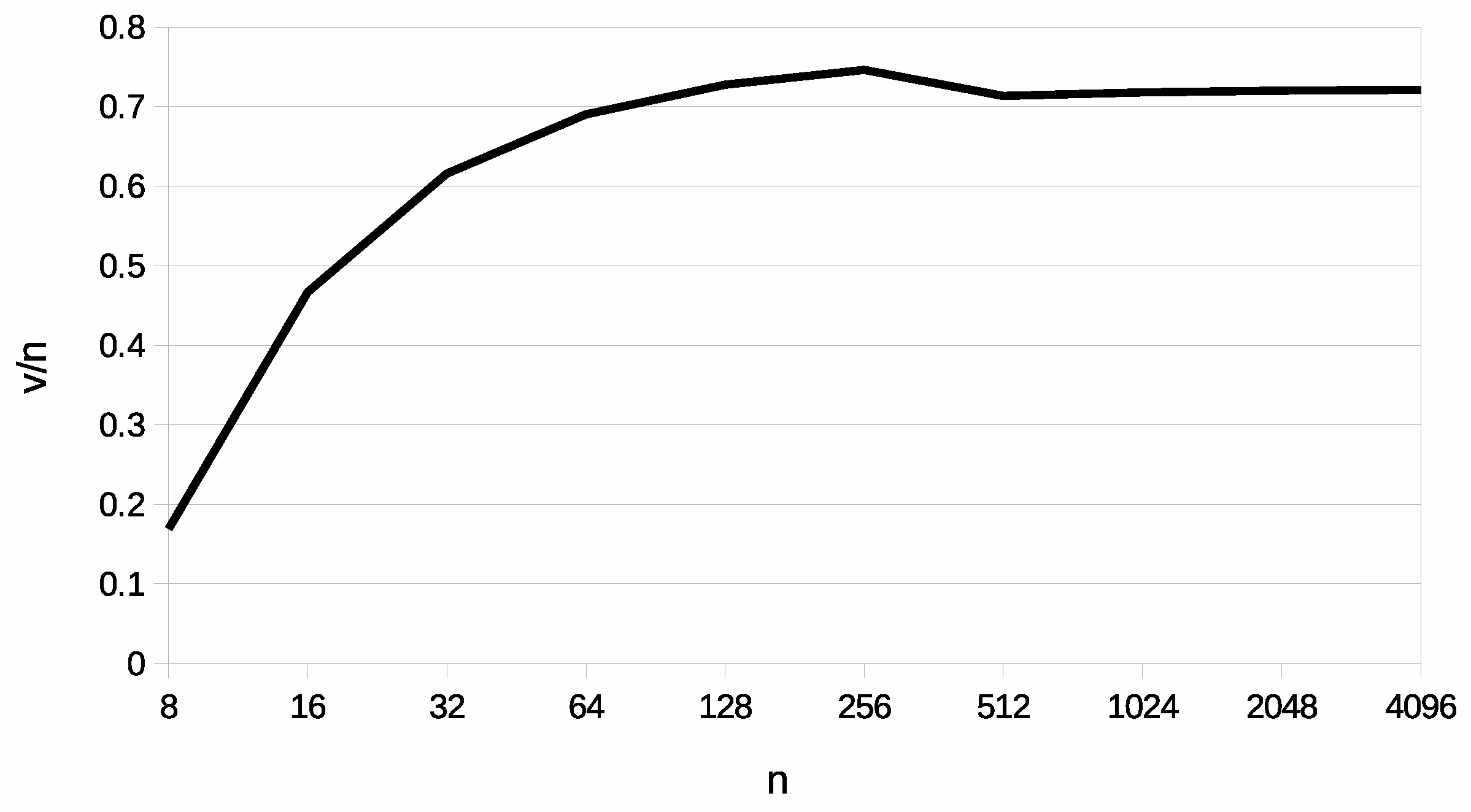
Considering the previous example, Figure 5 shows the ratio between the quantity of nodes in direct communication and the size of the network at which PCAT and FPWK require the same memory area. Therefore, if the ratio is under the curve (i.e., a node is directly connected with a percentage of nodes lower than that ratio), the proposed approach can be applied to networks composed of a larger number of nodes with respect to FPWK. In the chart, the ratio normally increases, with the only exception of a small decrease when the increasing number of nodes requires an additional byte to store ID. However, it is observed that PCAT is generally better than FPWK if the nodes are in direct communication with less than 70% of the nodes in the network.
The size of the memory area used for the secret material is also significant for the other state-of-the-art approaches. The schemes based on the random predistribution of secret material provide a higher level of security if they store a large quantity of secret material. The additional parameters are:
- the quantity of keys per ring stored by each node (r),
- the size of the identification of the keys (),
- the size of the seeds used by RSDTMK (),
- the size of the identification of the seeds (), and
- the total quantity of keys stored by RSDTMK ().
LEAP+, FLEAP and SKKE require a pairwise key per link. PGK has the lowest request, since only one key must be stored. Although SSL requires a large memory area, but fixed. The additional parameter represents the length of a signature with public-key cryptography.
Let us consider the following case study: bytes, byte, byte, bytes, bytes, bits, bytes and byte (2 in RSDTMK). During the working phase, the memory used to store secret material in PCAT 535 bytes, in FPWK 1584 bytes, in EG 190 bytes, in 2C 340 bytes, in 1–5C is 246 bytes, in RSDTMK 282 bytes, in SSL 160 bytes, in PGK 16 bytes, in LEAP+, FLEAP and SKKE 186 bytes. These dimensions can be compared with the storage area of the MSP430 microcontroller on Tmote Sky, which features 10 kB of RAM and 48 kB of Flash memory.
4.4. Communication Efficiency
PPWK and PGK do not require any key establishment, since each node knows the key matched to all its links.
Table 2 shows the communication efficiency for the state-of-the-art schemes and PCAT. The new parameter represents the minimum length of an encrypted message with public encryption. In 2C, 1–5C, RSDTMK, LEAP+, FLEAP, EG, and SKKE, the key establishment involves the transmission of two one-hop messages with various sizes. In PCAT, four messages are required: two messages contain the ID of the sender and its public key, the other two messages contain the ID of the sender and an encrypted random number.
Considering bytes, bytes, bytes, , byte (2 in RSDTMK), bytes, bytes, and bytes, the key establishment in LEAP+ and FLEAP requires 18 bytes, in SKKE 67 bytes, in RSDTMK 40 bytes, in EG 29 bytes, in 2C 38 bytes, in 1–5C 33 bytes, in SSL 260 bytes, and in PCAT 196 bytes. Comparing the communication efficiency, PCAT has greater requirements than the schemes based on symmetric encryption, but not as many as SSL.
4.5. Computational Efficiency
The operations executed according to the various schemes can be summarized by:
- a pseudo-random function ,
- a permutation ,
- a MAC,
- a verification of a signature with public-key cryptography ,
- an asymmetric encryption and
- an asymmetric decryption .
PPWK, PGK and EG do not require computation. In LEAP+ an FLEAP, the initiator of the handshake computes a MAC and two functions, while the responder computes a MAC and an function. RSDTMK requires that both nodes compute a MAC, an and a function. SKKE requires that both nodes compute a MAC, an and a function. Also, 2C requires that both nodes execute an function. In SSL, both nodes execute one , , and function. In PCAT, both nodes execute one , and function. In 1–5C, only negligible operations are involved.
The computational overheads required by the PCAT are greater than in the state-of-the-art schemes based on symmetric encryption, but they are lower than in SSL, which requires a signature verification. Moreover, according to the energy consumption analysis executed in [17], the signature verification with public-key cryptography can require the double of the energy required for an encryption or a decryption.
4.6. Connectivity
The connectivity is calculated as the probability of successfully establishing a link with another node. Table 3 shows the formula of the connectivity for the considered schemes.
SSL, FPWK, PGK, SKKE, LEAP+ and FLEAP provide the same level of connectivity as PCAT: all the nodes are able to establish a link with any other node in the network. For the schemes based on the random key distribution, the parameter r, which represents the quantity of keys owned by a node, and p, which represents the total quantity of keys, determine the level of connectivity. EG, RSDTMK and 1–5C provide a lower connectivity, since only the nodes that share at least a key can establish a link. In 2C, two nodes are able to establish a link if they share at least two starting keys.
4.7. Resilience
The resilience corresponds to the ability to cope with the presence of compromised secret material. If an adversary compromises a node of a WSN, he/she could exploit the information stored by the compromised node to attack other parts of the network. Table 4, Table 5 and Table 6 show the probability that an opponent eavesdrops on a link between uncompromised nodes (rows with label ”link”) and the probability that a false node passes an authenticity check (rows with label ”check”).
By comparing PCAT to the other schemes for mobile networks, it is observed that the best level of resilience against eavesdropping is provided by FPWK, SSL and PCAT. The poorest level of resilience, corresponding to the theoretical minimum, is provided by PGK and SKKE. EG, 2C and 1–5C provide an intermediate value. If x nodes are compromised within the working phase, LEAP+ and FLEAP reach the best theoretical level of resilience, that is equal to PCAT. RSDTMK reaches a high level of resilience. If x nodes are compromised within the initialization phase, LEAP+ and FLEAP provide the worst level of resilience, like PGK and SKKE. RSDTMK provides the same level of resilience as EG.
Among the schemes for mobile networks, FPWK, SSL and PCAT provide the best resilience against false authentication. In addition, 2C and 1–5C provide a better resilience than EG, while PGK and SKKE provide no resilience. Among the schemes for static networks if the nodes are compromised in the working phase, LEAP+ and FLEAP provide the best resilience, like PCAT. RSDTMK reaches a level of resilience close to the optimum and better than 2C and 1–5C. If x nodes are compromised in the initialization phase, LEAP+ and FLEAP provide the worst level of resilience, like PGK and SKKE, while RSDTMK provides the same level of resilience as EG. Even in this case, FPWK, SSL and PCAT provide the best level of resilience.
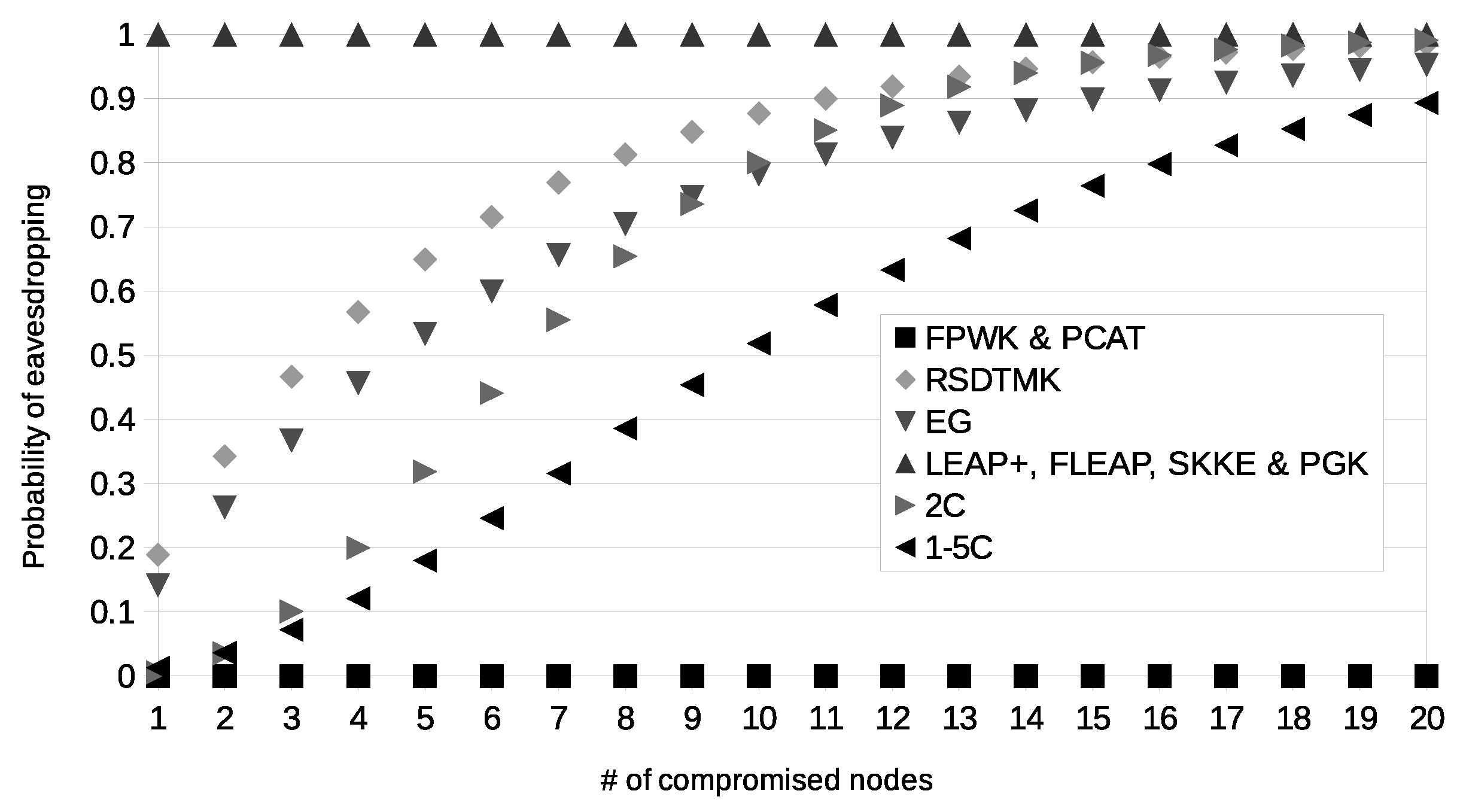
According to the described case study, and to the provided formulas, the limit of the network size of PCAT, according to (2), corresponds to 92 nodes, while the upper bound of FPWK, according to (1), is 33 nodes. Figure 6 and Figure 7 show the probability of eavesdropping if x nodes are compromised within the working phase or in the initialization phase, respectively. If x nodes are compromised, in SKKE, PGK, EG, 2C and 1–5C, the adversary can be recognized as a new authentic node by almost all the nodes of the network. In FPWK and PCAT, the adversary cannot be recognized as a new authentic node. In RSDTMK, LEAP+ and FLEAP, if the nodes are compromised within the working phase, the adversary can be recognized as a new authentic node by a negligible quantity of nodes, while if the nodes are compromised within the initialization phase, the adversary can be recognized as a new authentic node by almost all the nodes of the network.
4.8. Case Study Comparison
In this section, PCAT is compared with the state-of-the-art schemes. Table 7 shows the assumptions of the considered schemes. In order to obtain a quantitative comparison of the state-of-the-art schemes, a case study is modeled by following the subsequent methodology. A network where each node has 10 neighbors is considered. The size of the secret material is set as follows: the length of the symmetric keys bits, and the length of the public and private keys bits, the size of the mask , the length of the hash bits. The length of node IDs bytes and of the key IDs byte. The length of the signature in SSL is . For 2C, RSDTMK and EG the best r and p are selected so that the upper bound to the memory storage is of the RAM of Tmotes Sky (512 bytes). A connectivity ≥0.99 has been selected as a constraint for all the schemes. Since in the schemes based on random distribution (i.e., EG, 2C, 1–5C, RSDTMK) the connectivity is better with high values of r and since r affects the storage, the highest value of r compliant with the storage constraint has been selected. Finally, the highest value of p that is compliant with the connectivity constraint has been selected. A high value of in RSDTMK increases the level of resilience, but also the memory storage. In order to provide a high level of resilience with limited drawbacks, is set to 8. The resulting values are: for EG, , ; for 2C, , ; for 1–5C, , ; and for RSDTMK, , .
The proposed scheme always provides the best resilience, as with FPWK and SSL. LEAP+ and FLEAP also provide the best level of resilience if the nodes are not compromised during the initialization phase, otherwise their level of resilience is the poorest. The level of resilience for RSDTMK is close to the optimum if the nodes are not compromised during the initialization phase. An intermediate level of resilience is provided by 2C, 1–5C and EG. In particular, 1–5C is better than 2C and EG.
4.9. Overall Comparison
The best scheme to protect a WSN depends on the characteristics of the network. In order to select which scheme represents the best solution the following methodology is adopted:
- the eligible schemes must be compliant with the requirements of the networks: the size of the network, the density of the nodes, the mobility of the nodes, the possibility to compromise a node during the initialization phase, the node adding, the deployment knowledge;
- the eligible schemes must be secure against injection of false messages and replay attacks;
- if an eligible scheme provides the best resilience independently from the quantity of compromised nodes, it is the best scheme;
- if a scheme provides the best level of resilience only for a specific quantity of compromised nodes (i.e., not independently of the quantity of compromised nodes), it is the best scheme in concurrence with other schemes;
- if two schemes have the same level of resilience, the scheme that requires less computational and communication overheads is the best scheme.
Figure 8 shows the diagram of the best schemes for mobile networks and for static WSN with the assumption that a node can be compromised during the initialization phase. FPWK represents always the best solution for small networks. Otherwise, PCAT represents the best scheme for medium size networks without a high density. For the other types of network, SSL is the best solution.
5. Protocol Implementation
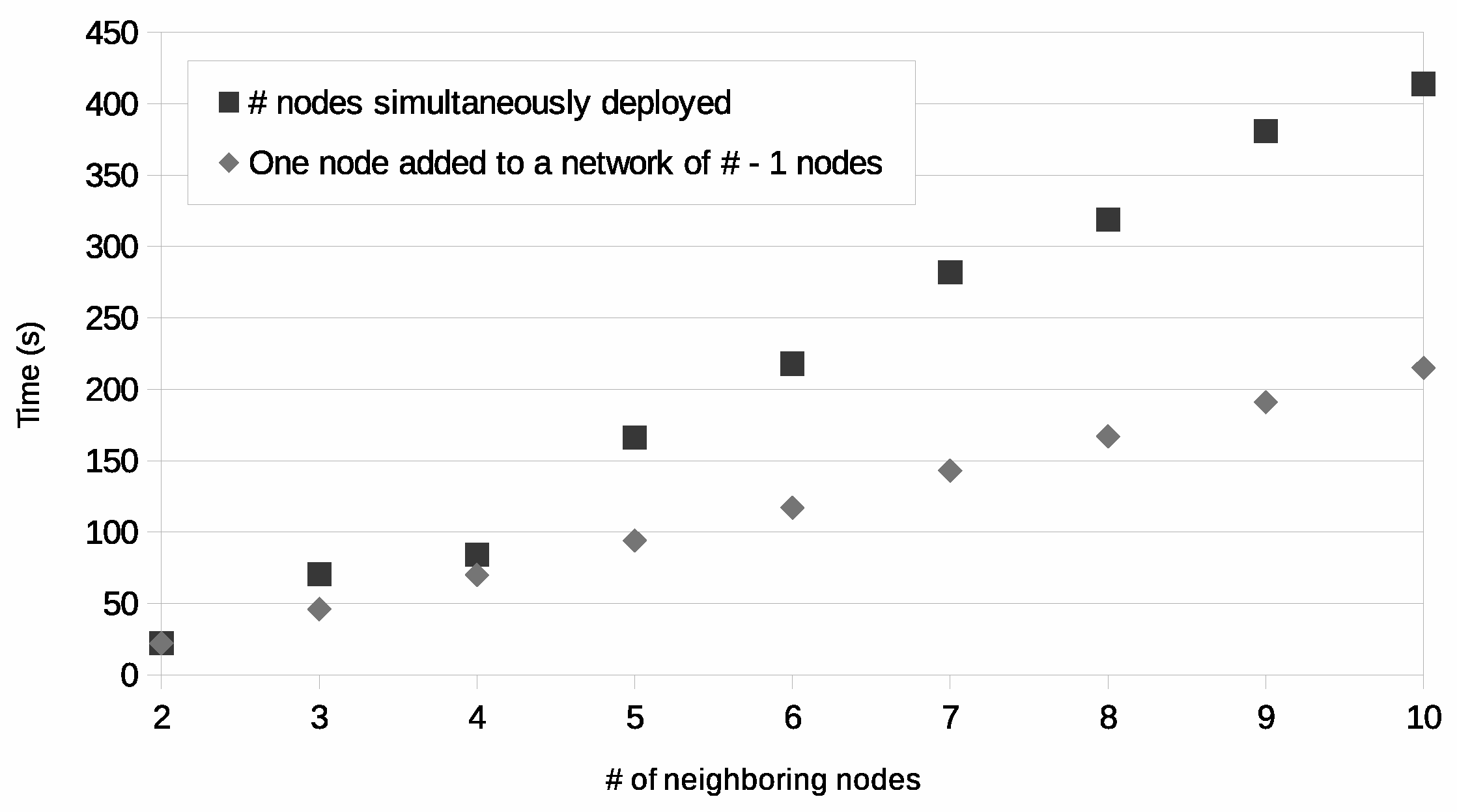
A prototype implementation has been developed in order to verify if it is compliant with the capability of a real WSN. Since in a real implementation on low cost devices many issues can compromise the activity of the nodes, a key establishment is considered completed when 95% of the possible pairwise keys have been established. The adopted public cryptosystem is the ECC. According to the National Institute of Standards and Technology (NIST, www.nist.gov) guidelines, ECC provides the same level of security of AES with 128-bit keys, by using 256-bit keys. The adopted WSN platform was composed of 10 Tmote sky devices with TinyOS [28]. The developed code was written in language [29]. The nodes are programmed to avoid a new handshake before the end of the current one. A timeout is used to abort erroneous too long handshakes. In this way, the nodes do not require to save the data required by several simultaneous handshakes.
In order to analyze the performance of PCAT, the key establishment has been executed on networks with different levels of density (i.e., from 2 to 10 neighbors per node), and each test has been iterated 10 times. The time required to complete the key establishment is shown in Figure 9. The chart reports the time required for the establishment if the nodes are deployed simultaneously and if one node is added to a previously deployed node. In the latter case, the quantity of messages is strongly lower, therefore there are less collisions among messages and the time required to complete the key establishment is limited.
6. Conclusions
In this paper, a new key management scheme for wireless sensor networks, called PCAT, has been proposed. The new scheme exploits public-key cryptography to protect the key establishment and an authentication mechanism guarantees that only eligible nodes can join the WSN. An in-depth analysis has shown that PCAT represents the best solution for medium size mobile WSNs with limited density. Moreover, if the assumption of transitory master key schemes (i.e., that an adversary is not able to compromise a node before a timeout) is not considered valid, PCAT would represent the best choice for medium size static WSNs with a limited density.
Acknowledgments
This work was partially supported by the grant Bando Smart Cities and Communities, Progetto OPLON (OPportunities for active and healthy LONgevity) funded by Ministero Istruzione, Universita’ e Ricerca, Italy.
Author Contributions
Cesare Celozzi proposed the original idea, Filippo Gandino designed the final protocol and Maurizio Rebaudengo coordinated the whole activity.
Conflicts of Interest
The authors declare no conflict of interest.
References
- Alías, F.; Socoró, J.C. Description of Anomalous Noise Events for Reliable Dynamic Traffic Noise Mapping in Real-Life Urban and Suburban Soundscapes. Appl. Sci. 2017, 7, 146. [Google Scholar] [CrossRef]
- Rezaee, A.A.; Yaghmaee, M.H.; Rahmani, A.M.; Mohajerzadeh, A.H. HOCA: Healthcare Aware Optimized Congestion Avoidance and Control Protocol for Wireless Sensor Networks. J. Netw. Comput. Appl. 2014, 37, 216–228. [Google Scholar] [CrossRef]
- Gaj, P.; Jasperneite, J.; Felser, M. Computer Communication Within Industrial Distributed Environmenta—Survey. IEEE Trans. Ind. Inform. 2013, 9, 182–189. [Google Scholar] [CrossRef]
- Shin, H.; Own, C. Implementing a green bicycle alliance using a wireless sensor network. Int. J. Ad Hoc Ubiquitous Comput. 2014, 16, 103–112. [Google Scholar] [CrossRef]
- Wang, X.; Matetić, M.; Zhou, H.; Zhang, X.; Jemrić, T. Postharvest Quality Monitoring and Variance Analysis of Peach and Nectarine Cold Chain with Multi-Sensors Technology. Appl. Sci. 2017, 7, 133. [Google Scholar] [CrossRef]
- Yan, H.; Zhang, Y.; Pang, Z.; Xu, L.D. Superframe Planning and Access Latency of Slotted MAC for Industrial WSN in IoT Environment. IEEE Trans. Ind. Inform. 2014, 10, 1242–1251. [Google Scholar]
- Anisi, M.; Abdullah, A.; Coulibaly, Y.; Razak, S. EDR: Efficient data routing in wireless sensor networks. Int. J. Ad Hoc Ubiquitous Comput. 2013, 12, 46–55. [Google Scholar] [CrossRef]
- Kar, P.; Misra, S. Detouring dynamic routing holes in stationary wireless sensor networks in the presence of temporarily misbehaving nodes. Int. J. Commun. Syst. 2015. Available online: http://onlinelibrary.wiley.com/doi/10.1002/dac.3009/abstract (accessed on 16 June 2015). [CrossRef]
- Vales-Alonso, J.; Costas-Rodríguez, S.; Bueno-Delgado, M.; Egea-López, E.; Gil-Castiñeira, F.; Rodríguez-Hernández, P.; García-Haro, J.; González-Castaño, F. An Analytical Approach to the Optimal Deployment of Wireless Sensor Networks. Comput. Intell. Remote Sens. 2008, 133, 145–161. [Google Scholar]
- Benzaid, C.; Lounis, K.; Al-Nemrat, A.; Badache, N.; Alazab, M. Fast Authentication in Wireless Sensor Networks. Future Gener. Comput. Syst. 2016, 55, 362–375. [Google Scholar] [CrossRef]
- Zhang, J.; Varadharajan, V. Wireless sensor network key management survey and taxonomy. J. Netw. Comput. Appl. 2010, 33, 63–75. [Google Scholar] [CrossRef]
- Shamshirband, S.; Anuar, N.B.; Kiah, M.L.M.; Rohani, V.A.; Petković, D.; Misra, S.; Khan, A.N. Co-FAIS: Cooperative fuzzy artificial immune system for detecting intrusion in wireless sensor networks. J. Netw. Comput. Appl. 2014, 42, 102–117. [Google Scholar] [CrossRef]
- Zhu, W.T.; Zhou, J.; Deng, R.H.; Bao, F. Detecting node replication attacks in wireless sensor networks: A survey. J. Netw. Comput. Appl. 2012, 35, 1022–1034. [Google Scholar] [CrossRef]
- Chen, C.Y.; Chao, H.C. A survey of key distribution in wireless sensor networks. Secur. Commun. Netw. 2014, 7, 2495–2508. [Google Scholar] [CrossRef]
- Bala Krishna, M.; Doja, M.N. Deterministic K-means secure coverage clustering with periodic authentication for wireless sensor networks. Int. J. Commun. Syst. 2015. Available online: http://onlinelibrary.wiley.com/doi/10.1002/dac.3024/abstract (accessed on 24 September 2015). [CrossRef]
- Ünlü, A.; Levi, A. Two-Tier, Scalable and Highly Resilient Key Predistribution Scheme for Location-Aware Wireless Sensor Network Deployments. Mob. Netw. Appl. 2010, 15, 517–529. [Google Scholar] [CrossRef]
- Wander, A.; Gura, N.; Eberle, H.; Gupta, V.; Shantz, S. Energy analysis of public-key cryptography for wireless sensor networks. In Proceedings of the Third IEEE International Conference on Pervasive Computing and Communications, Washington, DC, USA, 8–12 March 2005; pp. 324–328. [Google Scholar]
- Lauter, K. The advantages of elliptic curve cryptography for wireless security. IEEE Wirel. Commun. 2004, 11, 62–67. [Google Scholar] [CrossRef]
- Sahoo, S.K.; Sahoo, M.N. An Elliptic-Curve-Based Hierarchical Cluster Key Management in Wireless Sensor Network. In Intelligent Computing, Networking, and Informatics: Proceedings of the International Conference on Advanced Computing, Networking, and Informatics, India, June 2013; Mohapatra, D.P., Patnaik, S., Eds.; Springer: New Delhi, India, 2014; pp. 397–408. [Google Scholar]
- Fan, X.; Gong, G. Accelerating signature-based broadcast authentication for wireless sensor networks. Ad Hoc Netw. 2012, 10, 723–736. [Google Scholar] [CrossRef]
- Yein, A.D.; Huang, Y.H.; Lin, C.H.; Hsieh, W.S.; Lee, C.N.; Luo, Z.T. Using a Random Secret Pre-Distribution Scheme to Implement Message Authentication in VANETs. Appl. Sci. 2015, 5, 973–988. [Google Scholar] [CrossRef]
- Eschenauer, L.; Gligor, V. A key-management scheme for distributed sensor networks. In Proceedings of the 9th ACM conference on Computer and Communications Security, New York, NY, USA, 18–22 November 2002; pp. 41–47. [Google Scholar]
- Chan, H.; Perrig, A.; Song, D. Random key predistribution schemes for sensor networks. In Proceedings of the Symposium on Security and Privacy, Berkeley, CA, USA, 11–14 May 2003; pp. 197–213. [Google Scholar]
- Gandino, F.; Ferrero, R.; Rebaudengo, M. A Key Distribution Scheme for Mobile Wireless Sensor Networks: q-s-Composite. IEEE Trans. Inf. Forensics Secur. 2017, 12, 34–47. [Google Scholar] [CrossRef]
- Zhu, S.; Setia, S.; Jajodia, S. LEAP+: Efficient security mechanisms for large-scale distributed sensor networks. ACM Trans. Sens. Netw. 2006, 2, 500–528. [Google Scholar] [CrossRef]
- Gandino, F.; Ferrero, R.; Montrucchio, B.; Rebaudengo, M. Fast Hierarchical Key Management Scheme With Transitory Master Key for Wireless Sensor Networks. IEEE Internet Things J. 2016, 3, 1334–1345. [Google Scholar] [CrossRef]
- Gandino, F.; Montrucchio, B.; Rebaudengo, M. Key Management for Static Wireless Sensor Networks With Node Adding. IEEE Trans. Ind. Inform. 2014, 10, 1133–1143. [Google Scholar] [CrossRef]
- Levis, P.; Madden, S.; Polastre, J.; Szewczyk, R.; Whitehouse, K.; Woo, A.; Gay, D.; Hill, J.; Welsh, M.; Brewer, E.; et al. TinyOS: An operating system for sensor networks. In Ambient Intelligence; Springer: Berlin/Heidelberg, Germay, 2005; pp. 115–148. [Google Scholar]
- Gay, D.; Levis, P.; von Behren, R.; Welsh, M.; Brewer, E.; Culler, D. The nesC Language: A Holistic Approach to Networked Embedded Systems. In Proceedings of the PLDI ’03 ACM Sigplan 2003 Conference on Programming Language Design and Implementation, New York, NY, USA, 8–11 June 2003; pp. 1–11. [Google Scholar]
Figure 1.
Example of data stored by the nodes with total number of nodes (, quantity of bits indexed by the mask (, and length of the public key (.
Figure 1.
Example of data stored by the nodes with total number of nodes (, quantity of bits indexed by the mask (, and length of the public key (.

Figure 2.
Handshake.

Figure 3.
Node reintroduction.

Figure 4.
Size upper bound for the network, according to the size of the memory used to store the secret material.
Figure 4.
Size upper bound for the network, according to the size of the memory used to store the secret material.
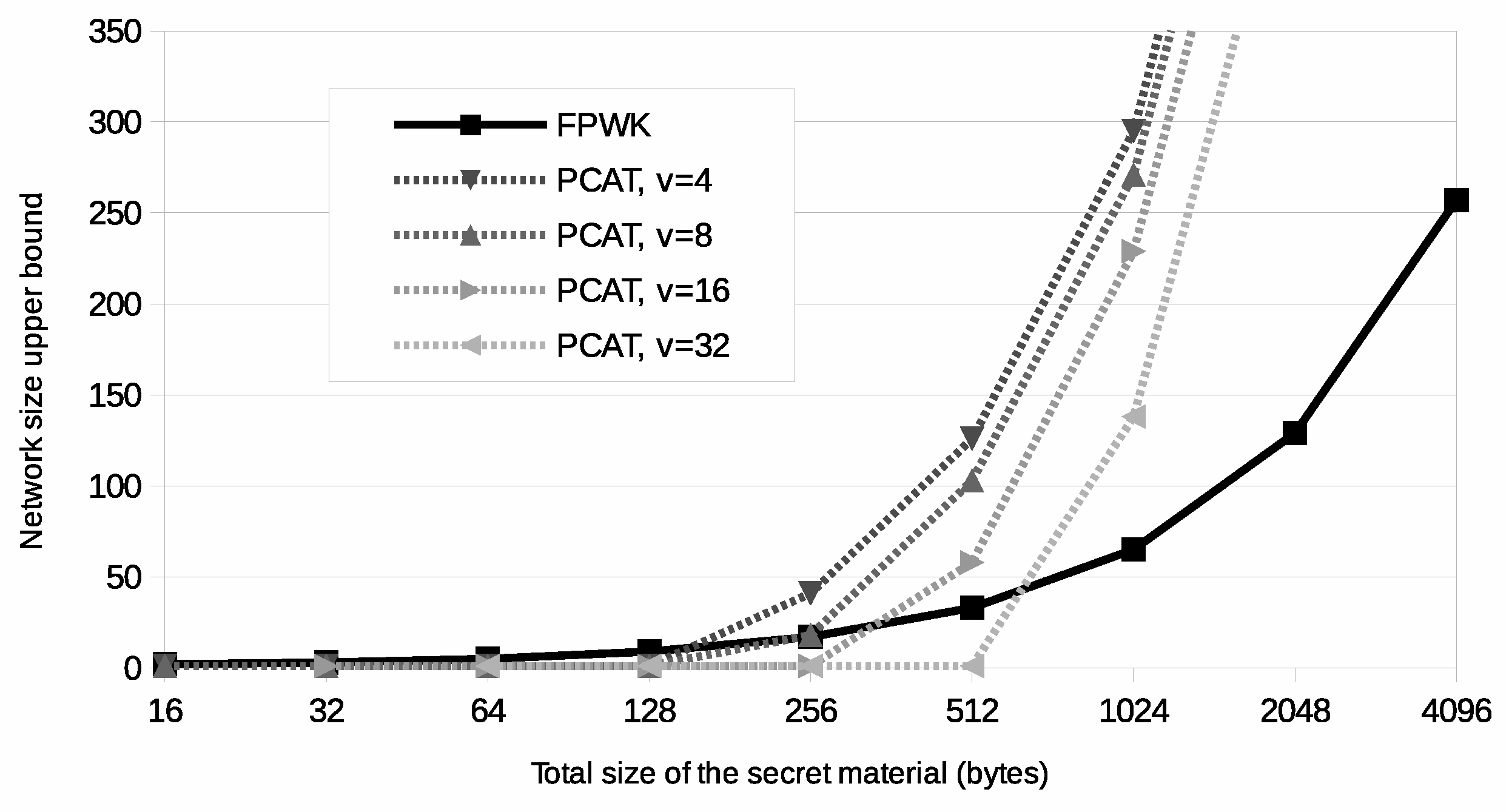
Figure 5.
Ratio between the number of nodes directly connected and the total quantity of nodes in the network at which PCAT and FPWK require the same memory area.
Figure 5.
Ratio between the number of nodes directly connected and the total quantity of nodes in the network at which PCAT and FPWK require the same memory area.

Figure 6.
Probability of eavesdropping on a link, according to the number of nodes compromised during the working phase.
Figure 6.
Probability of eavesdropping on a link, according to the number of nodes compromised during the working phase.

Figure 7.
Probability of eavesdropping on a link, according to the number of nodes compromised during the initialization phase.
Figure 7.
Probability of eavesdropping on a link, according to the number of nodes compromised during the initialization phase.

Figure 8.
Best schemes for mobile wireless sensor networks (WSNs) and for static WSN with the assumption that a node can be compromised during the initialization phase.
Figure 8.
Best schemes for mobile wireless sensor networks (WSNs) and for static WSN with the assumption that a node can be compromised during the initialization phase.
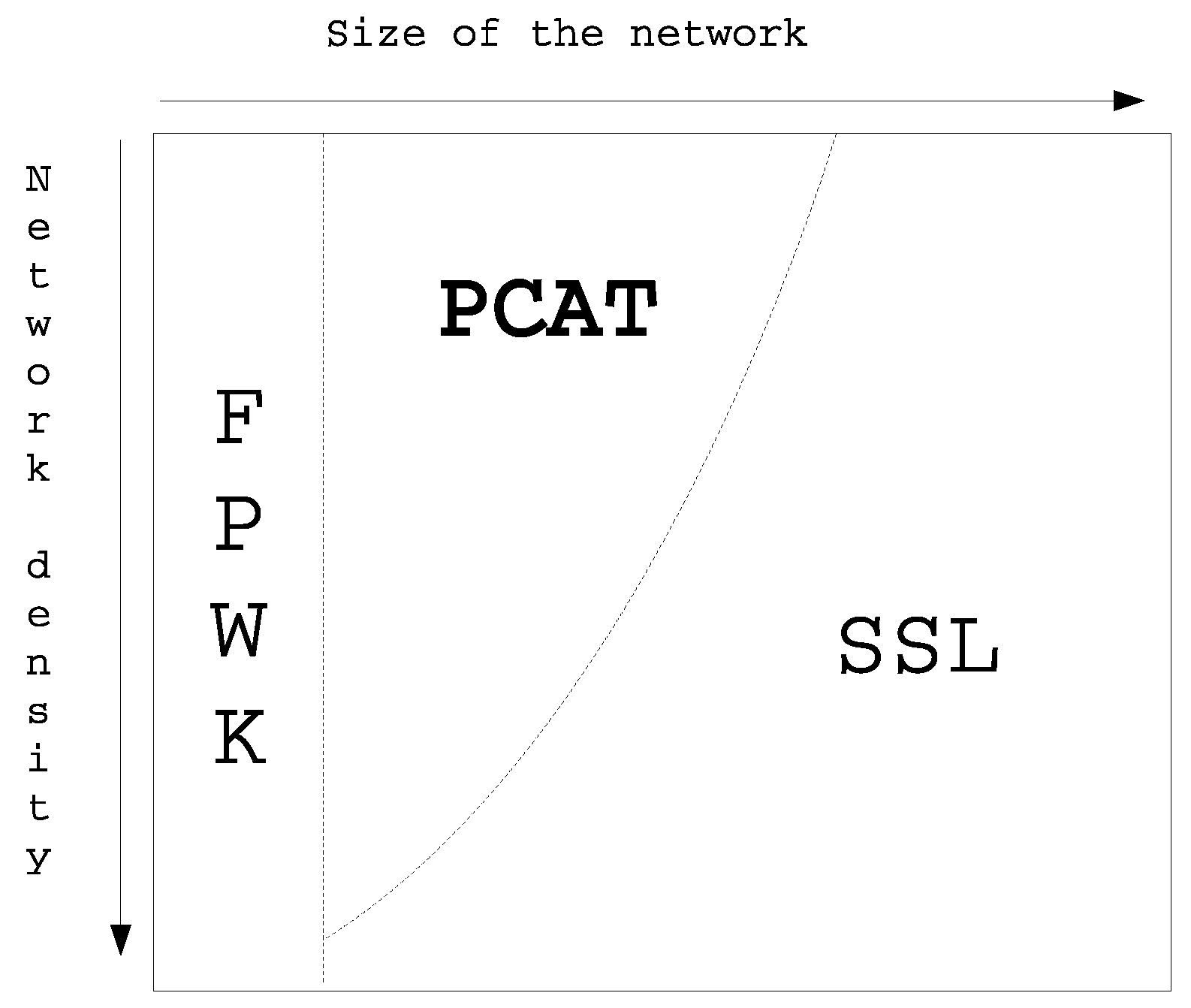
Figure 9.
Time required to complete the key establishment according to the density.


Table 1.
Memory required by the protocols. PCAT: public-key cryptography with authentication table; FPWK: full pairwise keys; EG: Eschenauer and Gligor key predistribution; 2C: q-composite with ; 1–5C: q-s-Composite with and ; RSDTMK: Random seed distribution with transitory master key; SSL: Secure Sockets Layer; PGK: plain global key; LEAP+: localized encryption and authentication protocol plus; FLEAP: fast LEAP; SKKE: symmetric-key key establishment.
| Scheme | Prestorage | Working |
|---|---|---|
| PCAT | ||
| FPWK | ||
| EG | ||
| 2C | ||
| 1–5C | ||
| RSDTMK | ||
| SSL | ||
| PGK | ||
| LEAP+ and FLEAP | ||
| SKKE |
Table 2.
Communication efficiency.
| Scheme | Messages | Size of the Transmitted Data |
|---|---|---|
| FPWK and PGK | 0 | 0 |
| LEAP+ and FLEAP | 2 | |
| SKKE | 2 | |
| RSDTMK | 2 | |
| EG | 2 | |
| 2C | 2 | |
| 1–5C | 2 | |
| SSL | 4 | |
| PCAT | 4 |
Table 3.
Connectivity.
| Scheme | Connectivity |
|---|---|
| FPWK, PGK, SKKE, LEAP+, FLEAP SSL and PCAT | 1 |
| EG, 1–5C RSDTMK | |
| 2C |
Table 4.
Resilience of state-of-the-art approaches for static networks when x nodes are compromised.
Table 4.
Resilience of state-of-the-art approaches for static networks when x nodes are compromised.
| Phase | Effect | LEAP+ and FLEAP | RSDTMK |
|---|---|---|---|
| Working | link | 0 | |
| check | 0 | ||
| Initialization | link | 1 | |
| check | 1 |
Table 5.
Resilience of random key distribution approaches when x nodes are compromised.
| Effect | EG | 2C | 1–5C |
|---|---|---|---|
| link | |||
| check |
Table 6.
Resilience of other approaches for mobile networks when x nodes are compromised.
| Effect | FPWK and PCAT | PGK and SKKE |
|---|---|---|
| link | 0 | 1 |
| check | 0 | 1 |
Table 7.
Assumptions.
| Protocols | Assumptions | ||
|---|---|---|---|
| Static Network | Deployment Knowledge | Network Size Limit | |
| SSL, 2C, 1–5C , EG, PGK and SKKE | NO | NO | NO |
| LEAP+, FLEAP and RSDTMK | YES | NO | NO |
| FPWK and PCAT | NO | NO | YES |
© 2017 by the authors. Licensee MDPI, Basel, Switzerland. This article is an open access article distributed under the terms and conditions of the Creative Commons Attribution (CC BY) license (http://creativecommons.org/licenses/by/4.0/).
Share and Cite
MDPI and ACS Style
Gandino, F.; Celozzi, C.; Rebaudengo, M. A Key Management Scheme for Mobile Wireless Sensor Networks. Appl. Sci. 2017, 7, 490. https://doi.org/10.3390/app7050490
AMA Style
Gandino F, Celozzi C, Rebaudengo M. A Key Management Scheme for Mobile Wireless Sensor Networks. Applied Sciences. 2017; 7(5):490. https://doi.org/10.3390/app7050490
Chicago/Turabian StyleGandino, Filippo, Cesare Celozzi, and Maurizio Rebaudengo. 2017. "A Key Management Scheme for Mobile Wireless Sensor Networks" Applied Sciences 7, no. 5: 490. https://doi.org/10.3390/app7050490
Note that from the first issue of 2016, this journal uses article numbers instead of page numbers. See further details here.