1. Introduction
The ballastless track is suitable for high-speed railways because it provides great smoothness and stability for the railway line, and has the advantages of high structural stability, good stiffness uniformity, long service life, and little maintenance work compared with the conventional ballast-track [
1,
2].
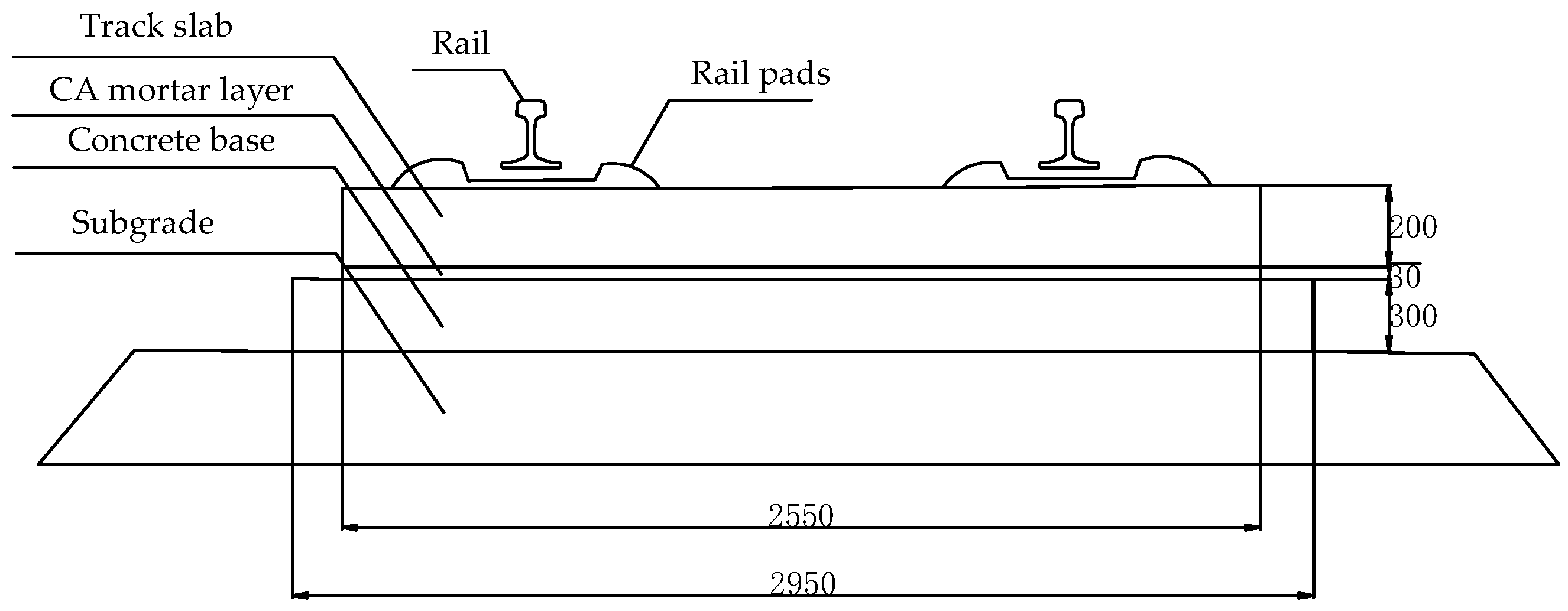
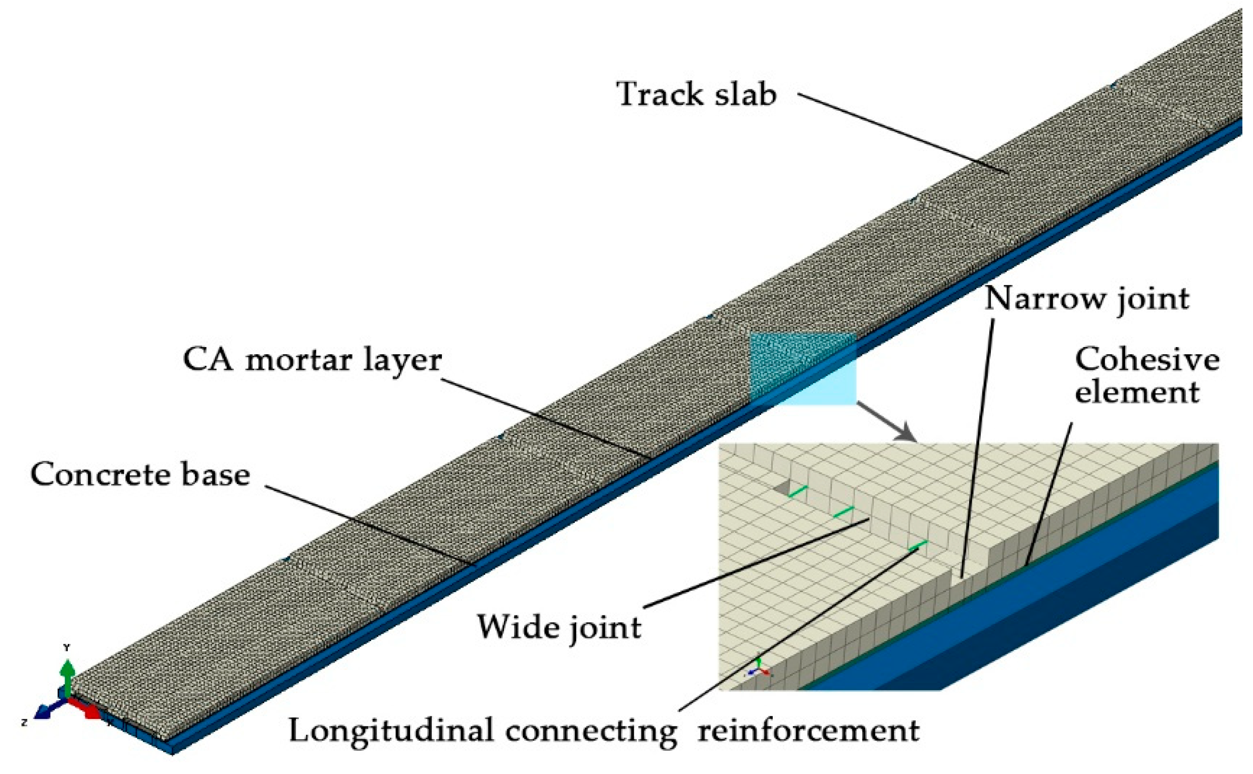
Figure 1 shows the CRTSII slab track and its components. The primary components of the slab track system are the rails, rail pads, track slab, cement-emulsified asphalt (CA) mortar layer, and concrete base. The CRTSII slab ballastless track is connected longitudinally between track slabs by tensioning the longitudinal connecting reinforcement between track slabs, and casting wide and narrow joint concrete [
3]. The tensioning of longitudinal reinforcement plays a role in ensuring the longitudinal connection reliability of the ballastless track and limiting the crack width at wide and narrow joints. According to the original design concept [
4], the tensioning of longitudinal reinforcement generates 300 kN of pre-pressure, which can effectively reduce the crack width and the stress of the connecting reinforcement on wide and narrow joint concrete. The wide and narrow joint is an important link in the longitudinal system of the CRTSII slab ballastless track.
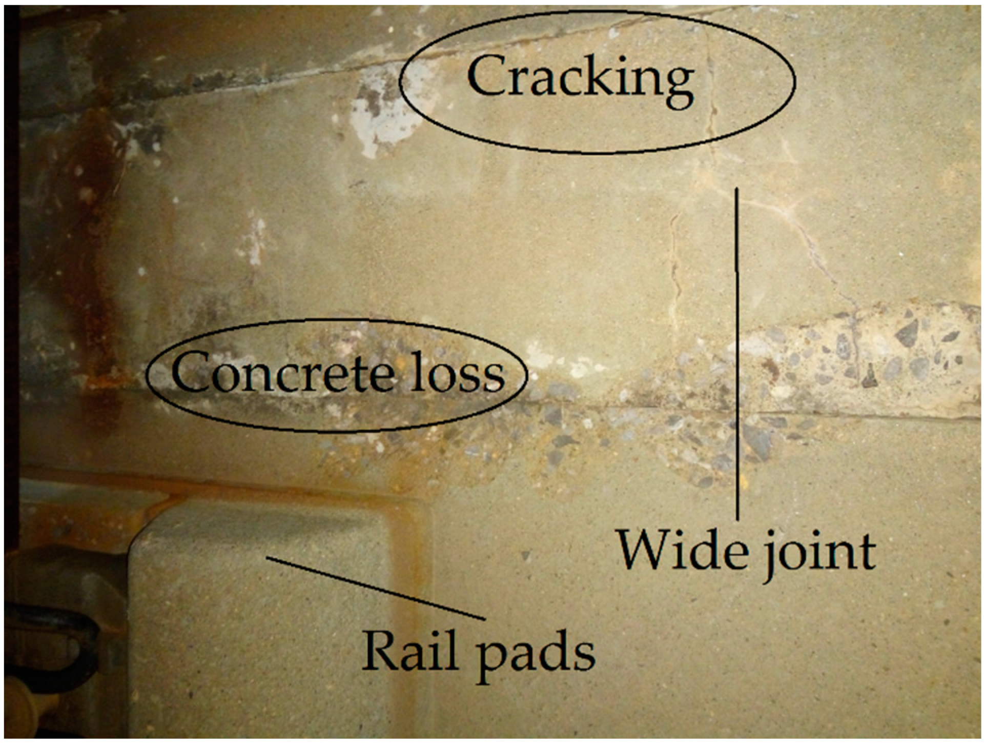
Although the slab track has gained successful improvements and applications in high-speed railway lines compared with traditional ballasted tracks, the slab track still sustains some structural damage caused by train load and temperature load in the operation process. In practice, the wide and narrow joints between the track slabs have presented deficiencies, such as concrete loss and damage, and cracking at joints (shown in
Figure 2) and arches, etc., in recent years. The longitudinal continuity and stability of the ballastless track are seriously weakened by the damage to the wide and narrow joint position. Therefore, it is necessary to study the mechanism of wide and narrow joint issues and to provide solutions for such joints’ maintenance and repair.
At present, most of the studies on wide and narrow joints of ballastless track mainly focuses on the generation of cracks and static and dynamic characteristics of wide and narrow joints under temperature load and train load. However, this cannot be effectively combined with the construction process. The influence of wide and narrow joint damage on the force and deformation of the seamless line, in temperature rise and continuous high temperature load based on the finite element theory, is studied in reference [
5]. The author claims that there are some problems in the original design concept, and that longitudinal connecting reinforcement does not provide pre-pressure on wide joint concrete. Reference [
6] investigated the influence of temperature load, interlayer state, and material quality on concrete damage at wide joints using the plastic damage constitutive model of concrete, and analyzed the causes of wide joint damage. Finite element simulation analysis on the effect of different tension-drawing processes on the force, exerted on the rail structure, was carried out in reference [
7]. It was concluded that the tension-drawing of the longitudinal reinforcement does not exert great pre-pressure on narrow joint concrete, and its effect on temperature resistance is not obvious. It can be seen that there is a design concept problem in the longitudinal connection of ballastless tracks. However, so far, very few studies have been published on the damage caused by the tensioning of longitudinal reinforcement in the construction stage; also, there is no research on fixing this problematic design concept.
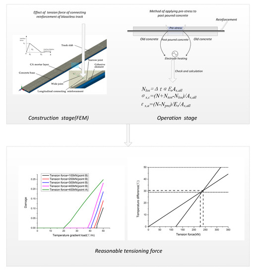
Based on the above analysis, this paper is divided into two parts (construction stage and operation stage) to study the tensile properties of longitudinal reinforcement. Firstly, the construction sequences of the CRTSII slab ballastless track in the wide and narrow joint position and the tensioning sequence of longitudinal reinforcement are briefly introduced in
Section 2. In
Section 3, the simulation model in the construction stage is introduced. The interface model parameters are determined through experimental data. The comparison between numerical results and experimental measurements is also reported. In
Section 4, different tension forces are selected as initial conditions to analyze the stress and deformation of the track structure after tensioning. Also, the influence of temperature gradient load on track structure failure after tensioning is analyzed according to environmental changes before the casting of wide joints. In
Section 5, a method of applying prestress to wide joint concrete is put forward to fix the error of the original design concept. Reasonable tension force is proposed after the stress of reinforcement and crack width of the concrete at the joint are checked and calculated, according to the concrete design principle [
8].
2. Longitudinal Joint Construction of CRTSII Slab Ballastless Track
2.1. Construction Sequence of Ballastless Track
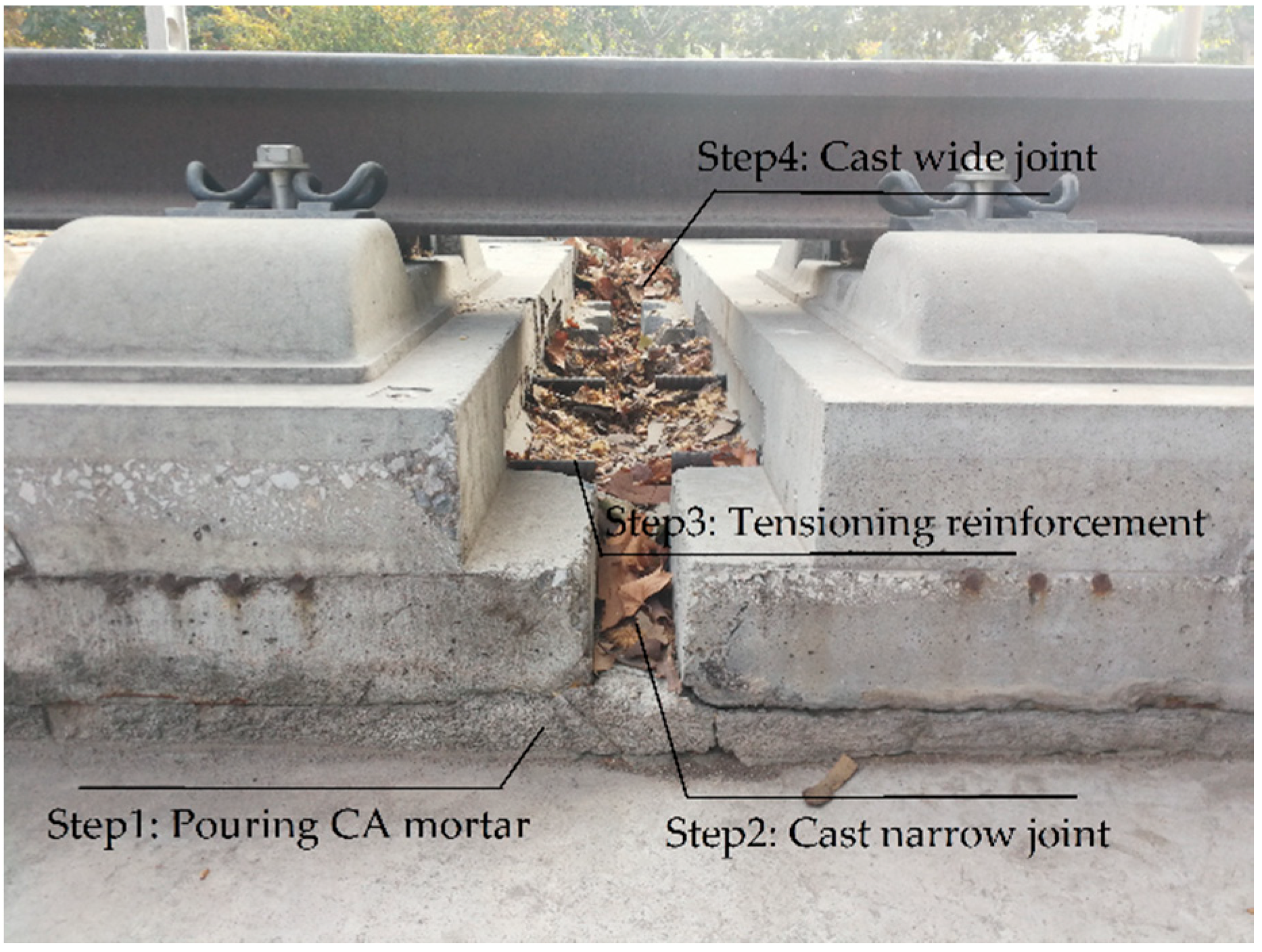
The construction sequence of the ballastless track is shown in the
Figure 3 (The track plate in the picture is used for teaching, not the actual operating line.) after casting the concrete base.
Step 1: Pouring CA mortar
The status of the track slab should be checked to make sure that its position meets the design requirements, and the concrete base should be pre-wetted before the CA mortar is poured. CA mortar is perfused through the perfusion holes in the middle of the track slab. The CA mortar for each track slab shall be perfused once for all.
Step 2: Cast narrow joint concrete
The pouring of the narrow joint should be carried out after CA mortar perfusion is completed and its strength reaches 7 MPa. The narrow joint height is controlled at 6 cm below the upper edge of the track slab.
Step 3: Tensioning longitudinal reinforcement
The tensioning process of reinforcement should be carried out after the strength of CA mortar reaches 9 MPa and the strength of the narrow joint concrete reaches 20 MPa. The specific tensioning sequence is detailed in
Section 2.2.
Step 4: Cast wide joint concrete
The concrete should be poured in time after the longitudinal reinforcement is connected. The tension force value should be rechecked before casting. After the casting is completed, it should be vibrated and compacted, and the concrete surface made flush with the surface of the track slab.
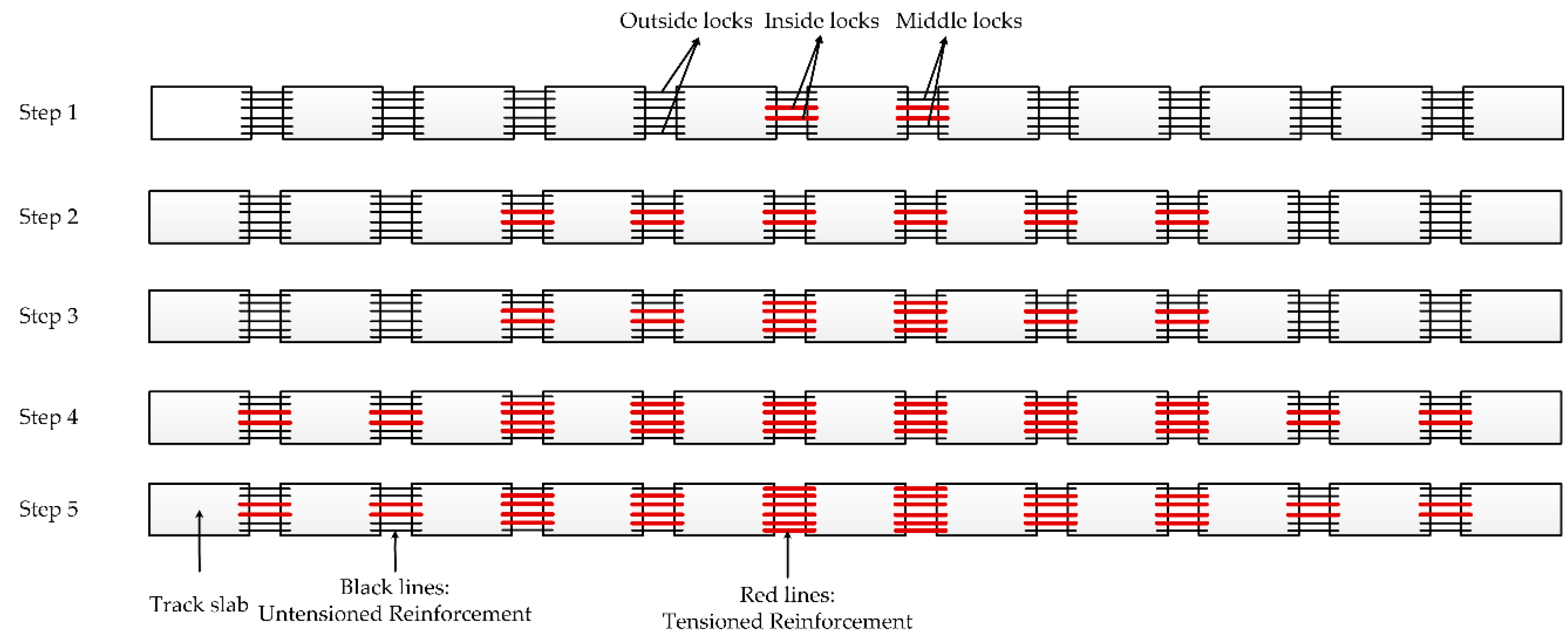
2.2. Tensioning Sequence of Longitudinal Reinforcement
Each wide and narrow joint is provided with six tension locks. First, the middle of the two locks (inside locks) is tensioned, then the two locks near the middle locks (middle locks) are tensioned and, finally, the two locks on the outermost side (outside locks) are tensioned. A total tension force of 300 kN is applied to six longitudinal reinforcement and each longitudinal reinforcement tension force is 50 kN.
Tensioning sequence:
Step1: Tension the inside locks of the two joints.
Step2: Symmetrically tension the two inside locks near the two joints that have been stretched. This tensioning step is carried out with two joints step by step.
Step3: Tension the middle locks of the two middle joints after the six inside locks have been stretched.
Step4: Continue symmetrically tensioning the two inside locks near the joints that have been stretched and, at the same time, tension the two middle locks near the joints that have been stretched.
Step5: Tension the outside locks of the two middle joints after the six middle locks have been stretched.
Longitudinal reinforcement is tensioned in this order until the completion of a construction section. The tensioning sequence is shown in
Figure 4.
4. Mechanical Analysis in Tensioning Process
Each longitudinal connecting reinforcement provided 50 kN tension force when the longitudinal connecting reinforcement of the ballastless track was stretched. The tension force was simulated by dropping the temperature, and the equivalent formula is
where Δ
t is the scale of drop in temperature, Δ
l is the length change of the wide joint,
l is the length of the wide joint,
α is the coefficient of linear expansion,
F is the tension value,
A is the section area of the longitudinal connecting reinforcement, and
E is the elastic modulus of the longitudinal connecting reinforcement.
The ballastless track is affected by the temperature load after the longitudinal reinforcement is stretched and before the casting of the wide joint, so only the temperature gradient load caused by daily temperature change was considered due to the short time interval between casting and stretching. Taking the common temperature gradient load into consideration, the positive temperature gradient load was 50 °C/m and the negative temperature gradient load was −25 °C/m. Temperature gradient loads were applied after the longitudinal reinforcement was tensioned. The designed tension load was 300 kN so, here, four calculation conditions of 100, 200, 300, and 400 kN were selected to analyze the influence of tension load.
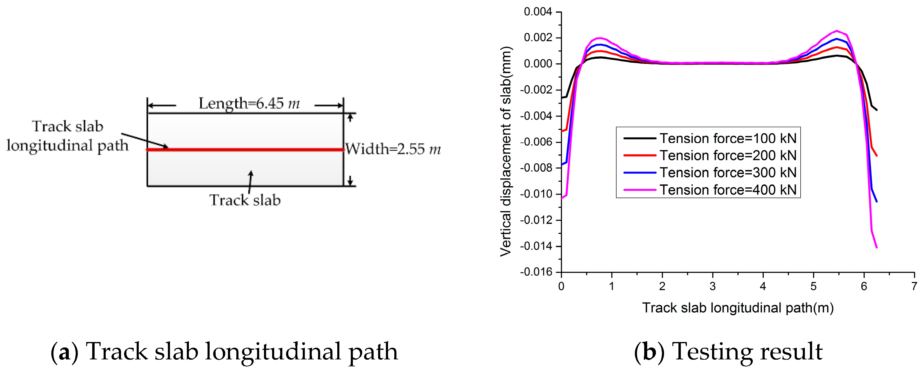
The vertical displacement of the bottom side of the track slab, after the longitudinally connected reinforcement was tensioned, is shown in
Figure 9. It can be seen that due to the narrow joint, the longitudinal connecting reinforcement puts the track slab under eccentric compression after stretching. When the narrow joint position is under compression, the track slab tends to arch upward. The arch displacement of the track slab increases from the position of the slab edge to the position 0.7 m away from the slab edge. The arch displacement of the track slab begins to decrease gradually and then tends to be very small from the position of 0.7 m away from the slab edge to the position of 2 m away from the slab edge. The larger the tensile force, the larger the arch displacement, and the relationship between the arch displacement and tensile force is nearly linear. The arch displacement of the track slab is very small (0.002 mm) for ballastless track structure.
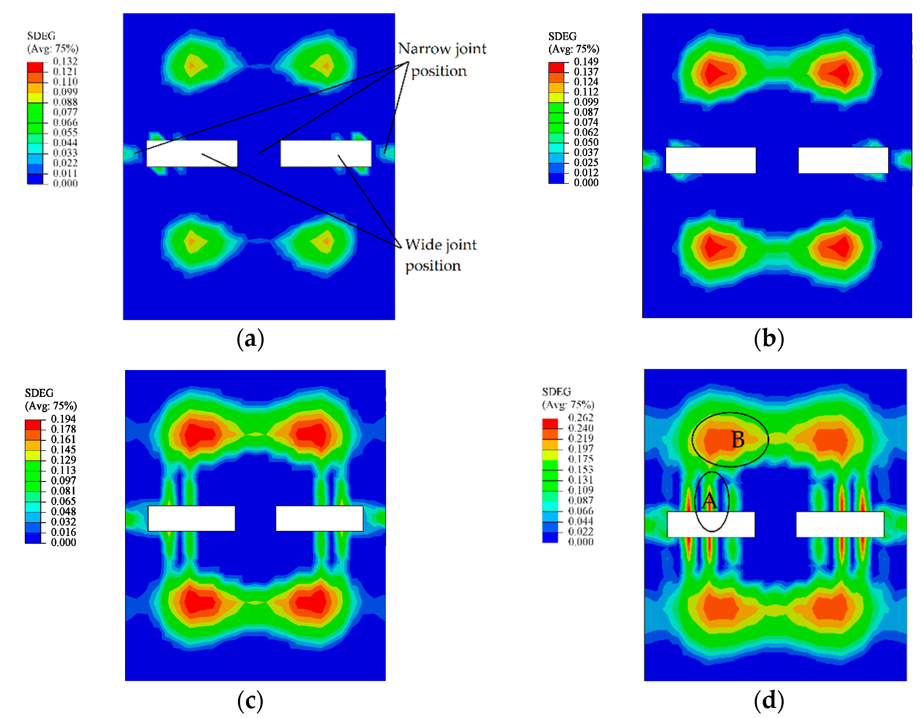
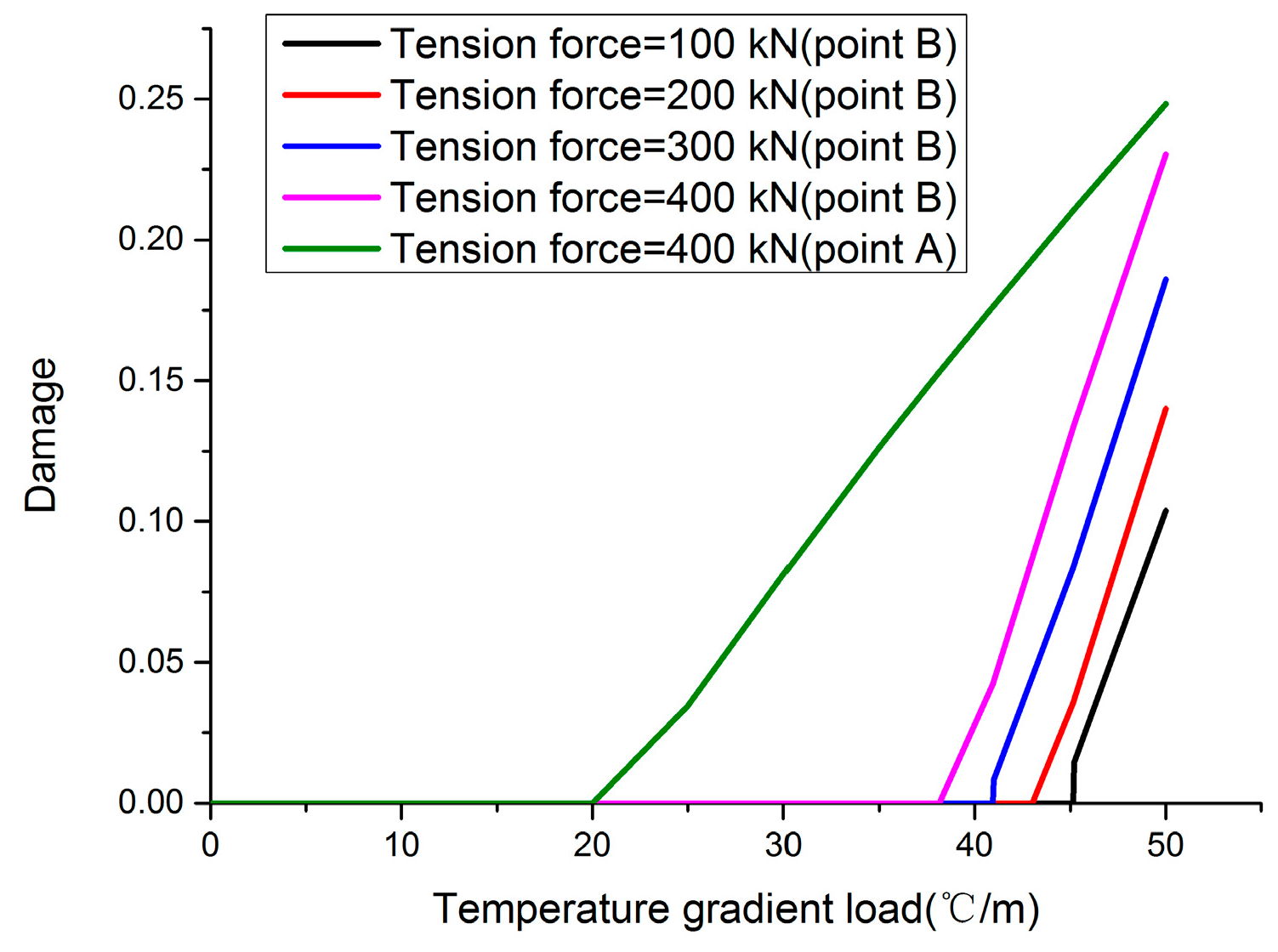
Figure 10 shows the damage at the interface between the track slab and CA mortar under the action of positive temperature gradient load with different tensile force values. It can be seen that the position of the interface damage is located 0.7 m away from the edge of the track slab and the edge of the track slab that corresponds to the outer reinforcement under the action of positive temperature gradient load. Both the damage value and the damage area increase with the increase of the tension force value. The position where the damage first appears is 0.7 m away from the edge of the track slab (point B), and the temperature gradient load value when the interface damage occurs is reduced from 46 to 40 °C/m when the tension force value increases from 100 to 300 kN (shown in
Figure 11). However, when the tension force value is 400 kN, the first damage area at the edge of the track slab (point A) and the corresponding temperature gradient load value is 20 °C/m, which suggests that the large tension force value is unfavorable to the interface at the end of the track slab.
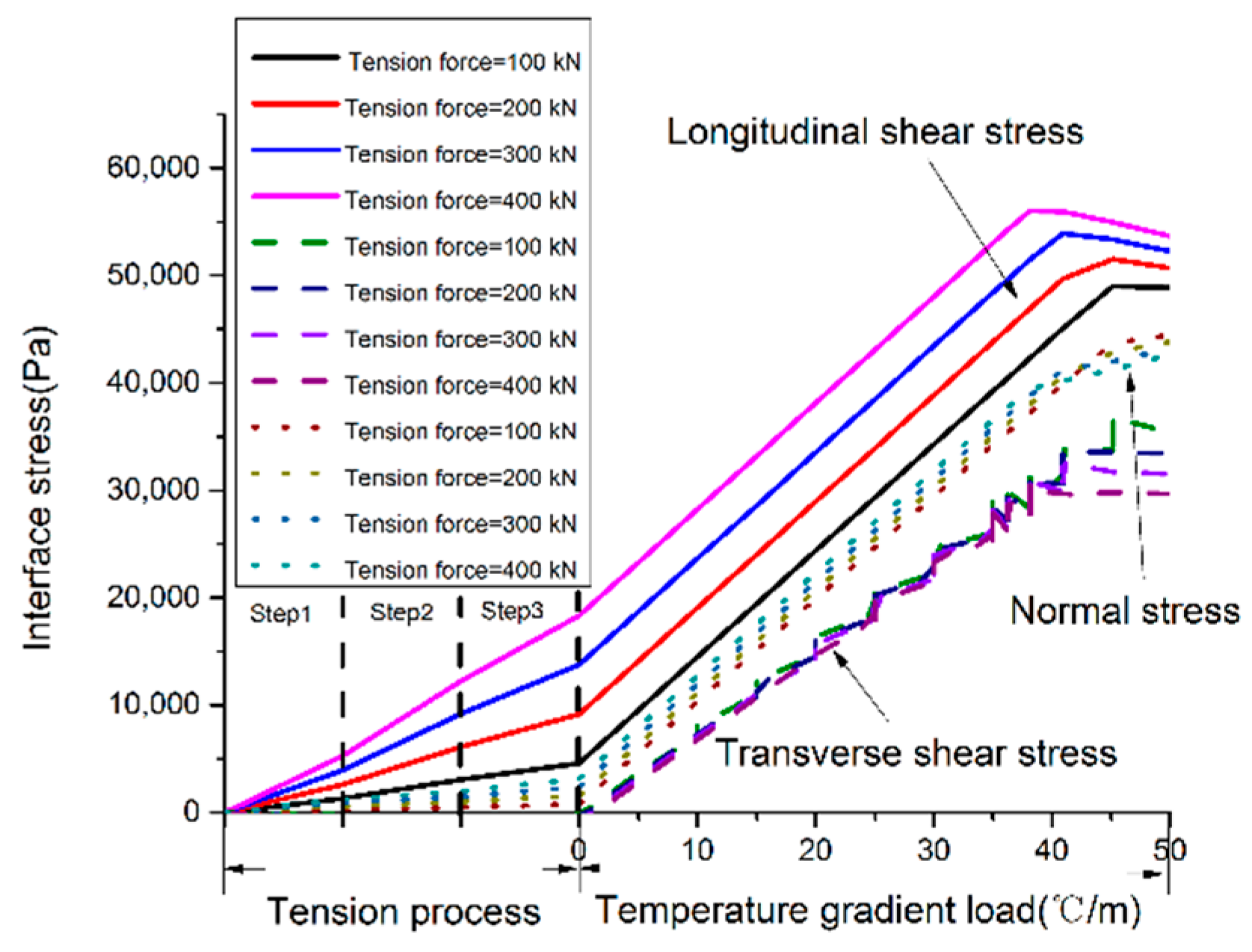
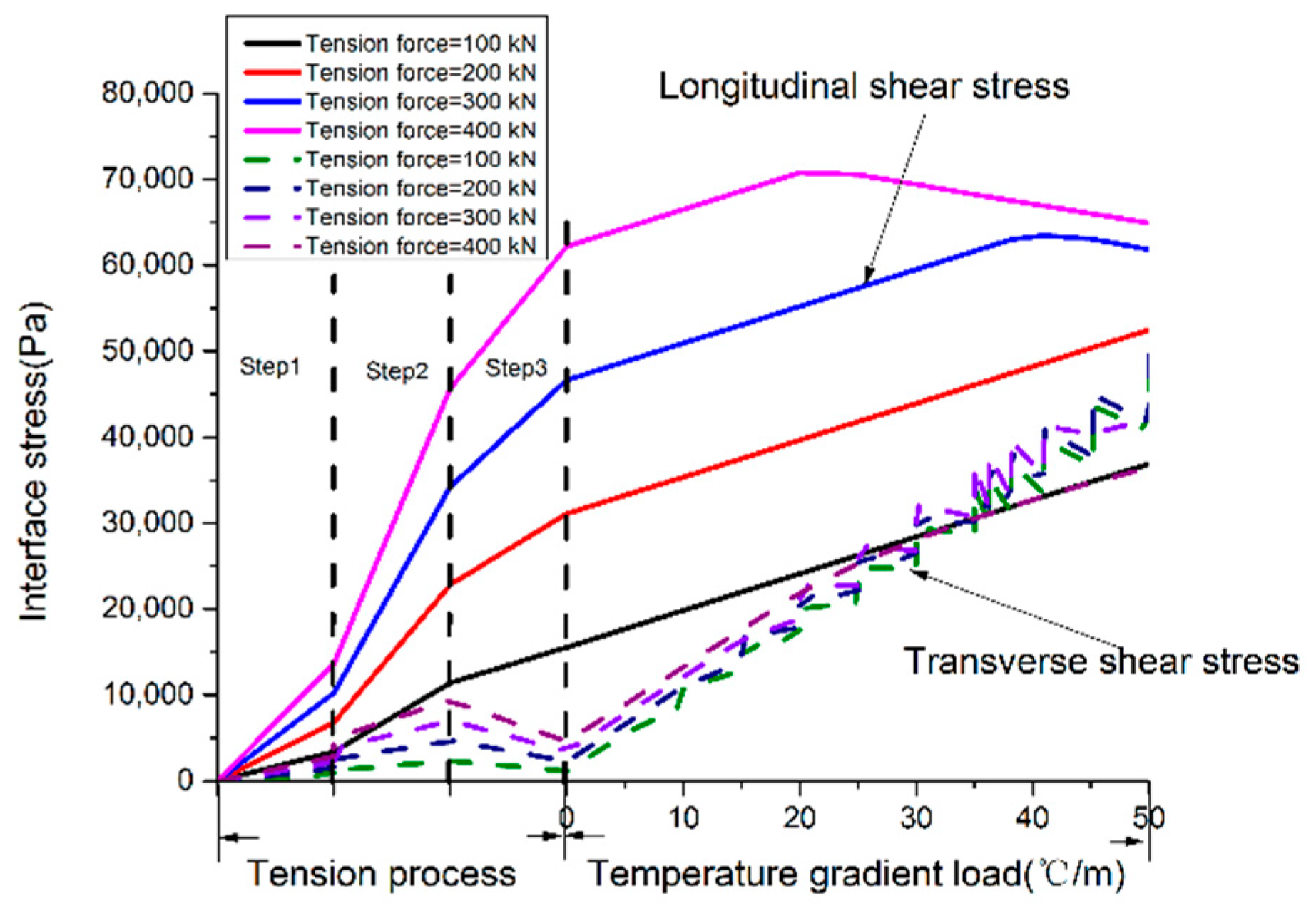
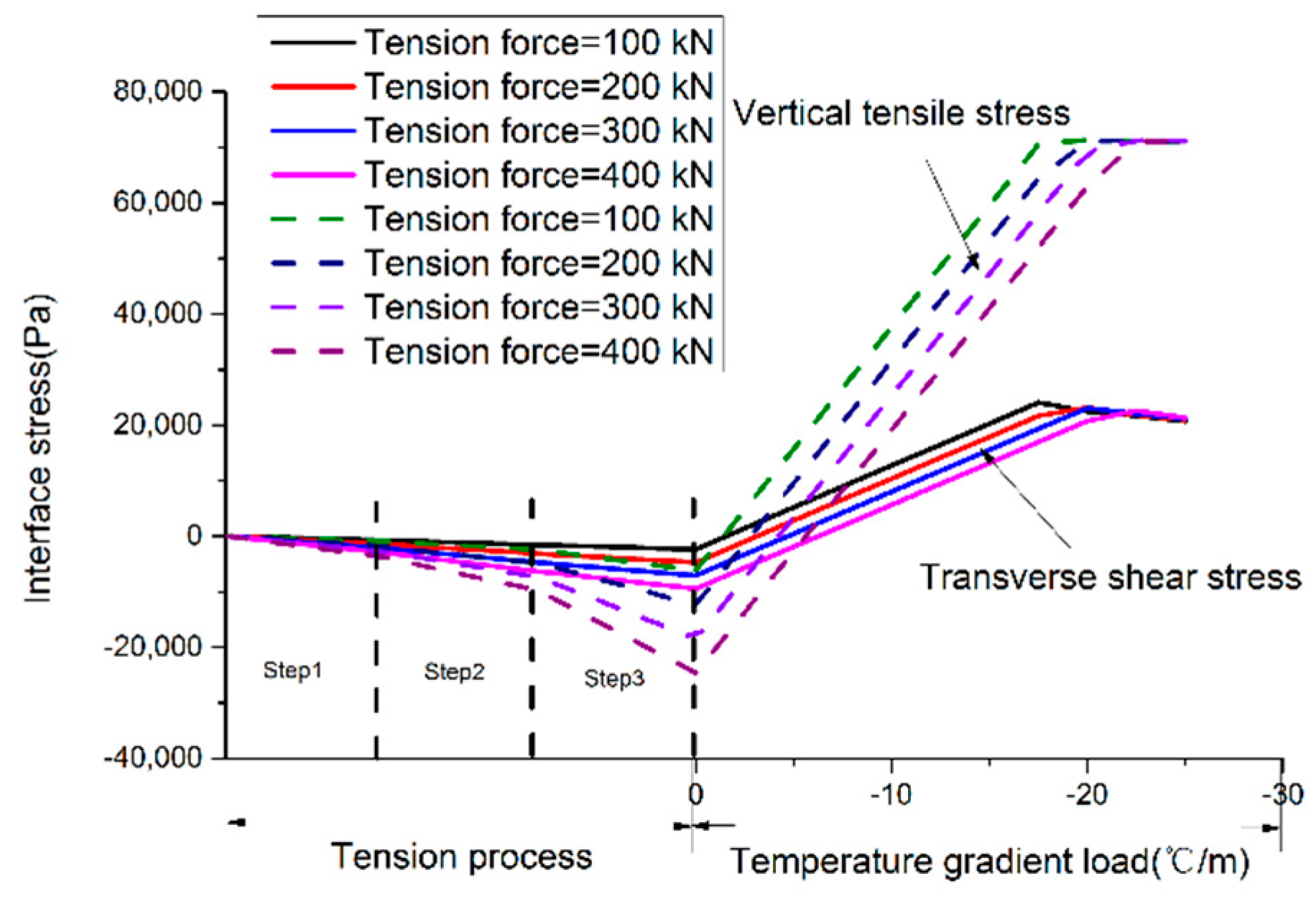
The stress condition of the element node at points A and B are shown in
Figure 12 and
Figure 13. It is longitudinal shear stress rather than the vertical normal stress and transverse shear stress that is most affected by tension force value. The three-direction stresses of the interface element increase linearly with the increase of positive temperature gradient load. The failure mode at point B is a mixed failure, for its three-direction stress are relatively large. Point A is subjected to 62,200 Pa of longitudinal shear stress when the tension process ends. When the positive temperature gradient load reaches 20 °C/m, Point A begins to appear damaged under longitudinal shear stress and transverse shear stress, so the failure mode at point A is shear failure.
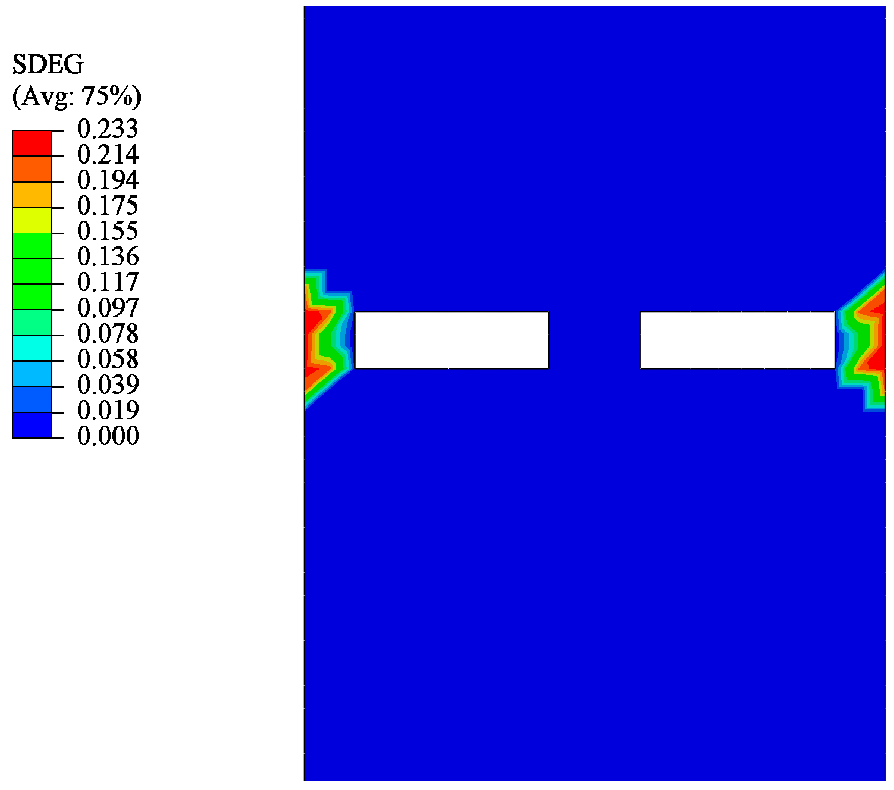
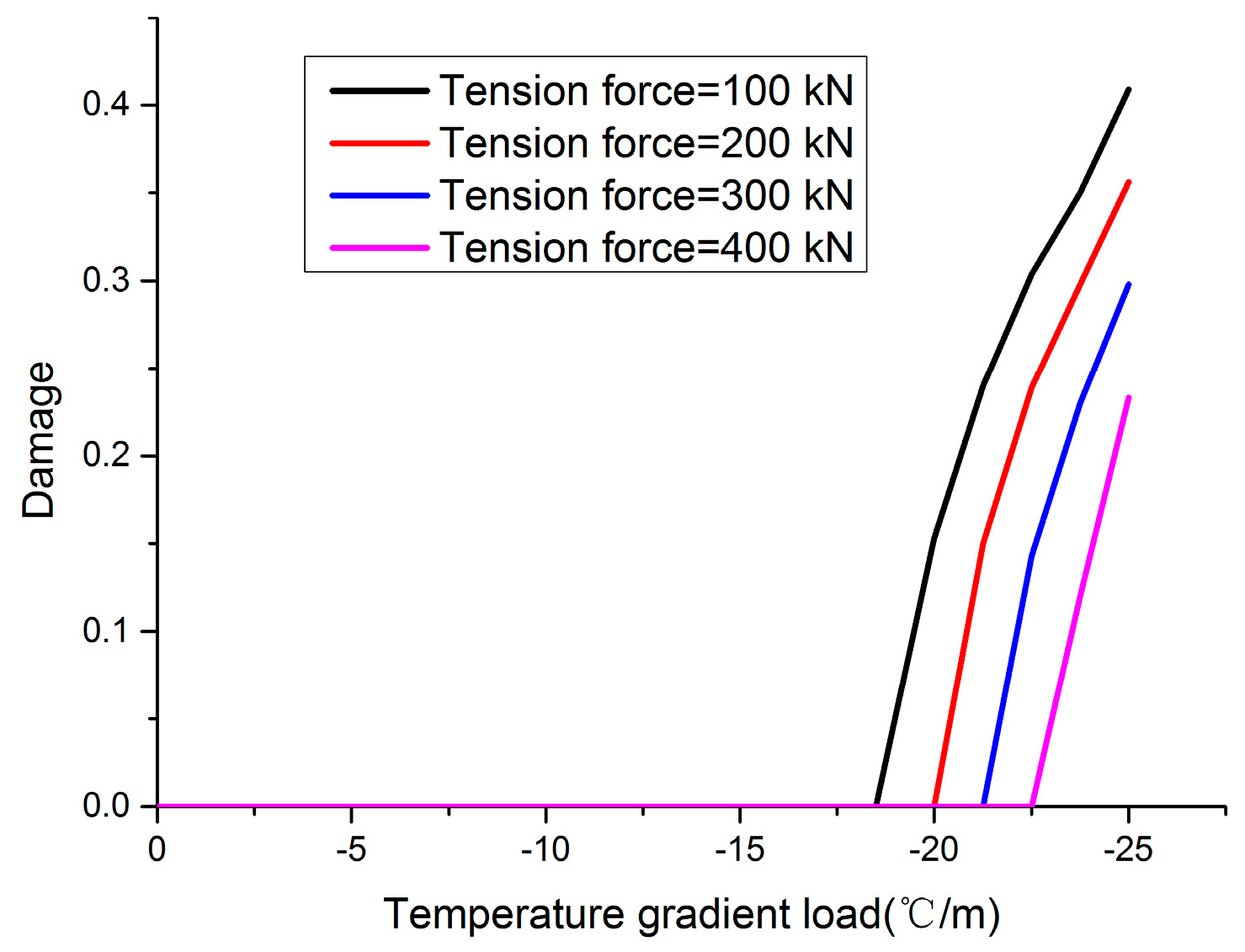
The interface damage areas, shown in
Figure 14, are located at the narrow joint position under the action of negative temperature gradient load with different tension force values. The damage value reduced from 0.453 to 0.233, and the temperature gradient load value when the interface damage occurs is reduced from −22.5 to −18.5 °C/m when the tension force value increases from 100 to 400 kN (as shown in
Figure 15). The stresses of the interface in the damaged area are shown in
Figure 16. Narrow joint position damage is mainly caused by vertical normal stress. The greater the tension force value, the greater the buckle pressure to the narrow joint position. So, the longitudinal tension of reinforcement can reduce the warping of the track slab corner.
The tension force of the longitudinal reinforcement has little effect on the deformation and stress of the track slab, however, interface damage occurs between the track slab and the mortar layer when subjected to temperature gradient load after the end of the tension process. For interface damage, the tension force of the longitudinal reinforcement increases the interface shear stress at the edge of the track slab and produces a downward depressing pressure, which could possibly increase its ability to resist negative temperature loads but reduce its ability to resist positive temperature gradient loads. Therefore, the casting of the wide joint should be carried out at the same time or as soon as possible after the longitudinal reinforcement is stretched, to avoid damage between the layers under a large temperature gradient load and ensure a reliable connection between the mortar layer and the track slab.
5. Check and Calculation in Operating Period
5.1. Original Design Check and Calculation
Three hundred kilonewtons of pre-pressure were applied to the concrete at the wide and narrow joint by applying 300 kN of longitudinal tension force to the longitudinal reinforcement between the track slabs in the design, and the track slab was considered as continuous in the longitudinal direction. The track slab was considered as the bar fixed at the beam end. Therefore, the strain of the track slab under the action of system temperature difference is
The shrinkage deformation, considered from 14 days to infinity of concrete, was carried out according to the specifications in [
8]. The contraction strain is
The stress of the reinforcement under the action of the live load was not taken into account. Only cooling and concrete shrinkage load were considered in the calculation because the longitudinal connecting reinforcement of the track slab was placed in the middle of the track slab. The stress of reinforcement is
where
Es is the elastic modulus of reinforcement.
There were only six Φ 20 connecting reinforcements in the joint of the track slabs. The stress of the reinforcement at the joint and the crack width was checked and calculated according to the tensile check result of the reinforcement inside the track slab. The axial force borne by the track slab was as Formula (7), under the combined action of cooling load and shrinkage load:
where
As is the cross-sectional area of a single connecting reinforcement.
The stress of reinforcement caused by shrinkage and cooling of concrete, in the future, should be superimposed on the stress caused by the tension of the connecting reinforcement, because the tension step occurred before the concrete casting step. In addition, the prestress of the joint cannot play a role in limiting the crack width, due to the fact that the joint concrete is not perfused when the tension force is applied to the connecting reinforcement.
The stress of the connecting reinforcement at the wide joint is
where
As,all is the total cross-sectional area of six reinforcements and
Nten is the tension force.
The average strain of reinforcement is
The crack width is checked and calculated according to the formula below:
where
ωcr is the calculated value of the crack width in mm,
lcr,max is the maximum crack spacing in mm,
εs,a is the average strain of reinforcement, and
εc,a is the average strain of concrete.
Take the distance (650 mm) between the false seam of track slab as lcr,max. As the strain of concrete is much smaller than that of reinforcement, the average strain of concrete is considered to be 0.
The limiting design value of reinforcement stress is 286 MPa, and the crack width is 0.5 mm according to the design specification [
8]. The reinforcement stress was 577.6 MPa, and the crack width was 0.65 mm as calculated by Equations (8) and (10), and both the calculation results did not meet the design requirements.
It can be seen from Equation (8) that the stress value of the connecting reinforcement can be reduced by reducing the tensile force of the connecting reinforcement. In order to reduce the crack width, the effective measures are to reduce the diameter of the connecting reinforcement or to apply prestress to the wide joint concrete.
5.2. Application of Prestress on Postcast Concrete
Temperature prestress loss can occur in steam curing causes for pretensioning prestressed concrete, because of the expansion of the prestressed reinforcement due to higher temperatures. When the concrete compressive strength reaches a certain strength grade, such as 7.5–10 MPa, the reinforcement and concrete are considered as a whole that can expand and contract together, without causing stress loss. However, for the wide joint concrete of the ballastless track, there is a design mistake. The prestressed reinforcement is not loose after the casting of wide joint concrete, which is different from pretensioning prestressed concrete, so it is not possible to generate prestress on wide joint concrete.
Here, we propose a method of applying prestress to postpouring concrete between the old concrete with reference to the concept of prestress loss for pretensioning prestressed concrete.
After the concrete is casted, electrode heating is applied to the connecting reinforcement, which makes the temperature increase for the connecting reinforcement. To attain the temperature difference between the pretensioned reinforcement and the cast concrete, we can apply thermal insulation material to the surface of the reinforcement. The pretensioned reinforcement relaxes to make the tension force decrease. When the concrete compressive strength reaches 7.5–10 MPa, the concrete and tensile reinforcement will deform together. When the concrete and reinforcement assume their initial temperature, a part of the tensile force of the reinforcement will be lost, and a part of prestress will be generated to the postpouring concrete, the prestress value of which is equal to the lost tensile force of the reinforcement.
5.3. Calculation of Reasonable Tension Value
The pretension loss value was determined by the temperature difference between the concrete and the reinforcement when the concrete and reinforcement deformed together. The pretension decreases (Equation (11)) when the temperature difference is Δt.
When the reinforced concrete deforms together,
The prestress of concrete Npre = Nlos.
At this time, the stress of the connecting reinforcement is
The strain of the connecting reinforcement is
From Equations (10), (11), and (13), it can be seen that the crack width is only related to the value of the prestress generated at the wide joint, while the prestress value is related to the temperature difference Δ
t inside the reinforced concrete.
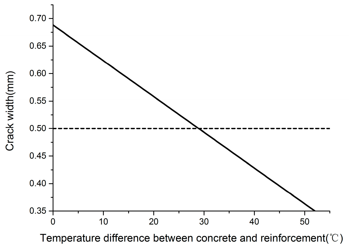
Figure 17 shows the relationship between the crack width and the temperature difference value between the concrete and the reinforcement. It can be seen that reinforcement and concrete temperature difference value should not be less than 29 °C, to guarantee the crack width is less than 0.5 mm.
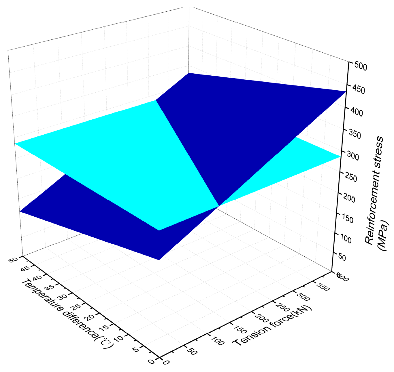
It can be seen from Equations (10) and (12) that the stress of reinforcement is related to the tension force and the internal temperature difference between concrete and reinforcement.
Figure 18 shows the three-dimensional diagram of stress, tension of reinforcement, and temperature difference. The stress of reinforcement is directly proportional to tension force and inversely proportional to temperature difference. According to the checked results of crack width, the temperature difference value should be greater than 29 °C. The three-dimensional figure is mapped to the tension in the
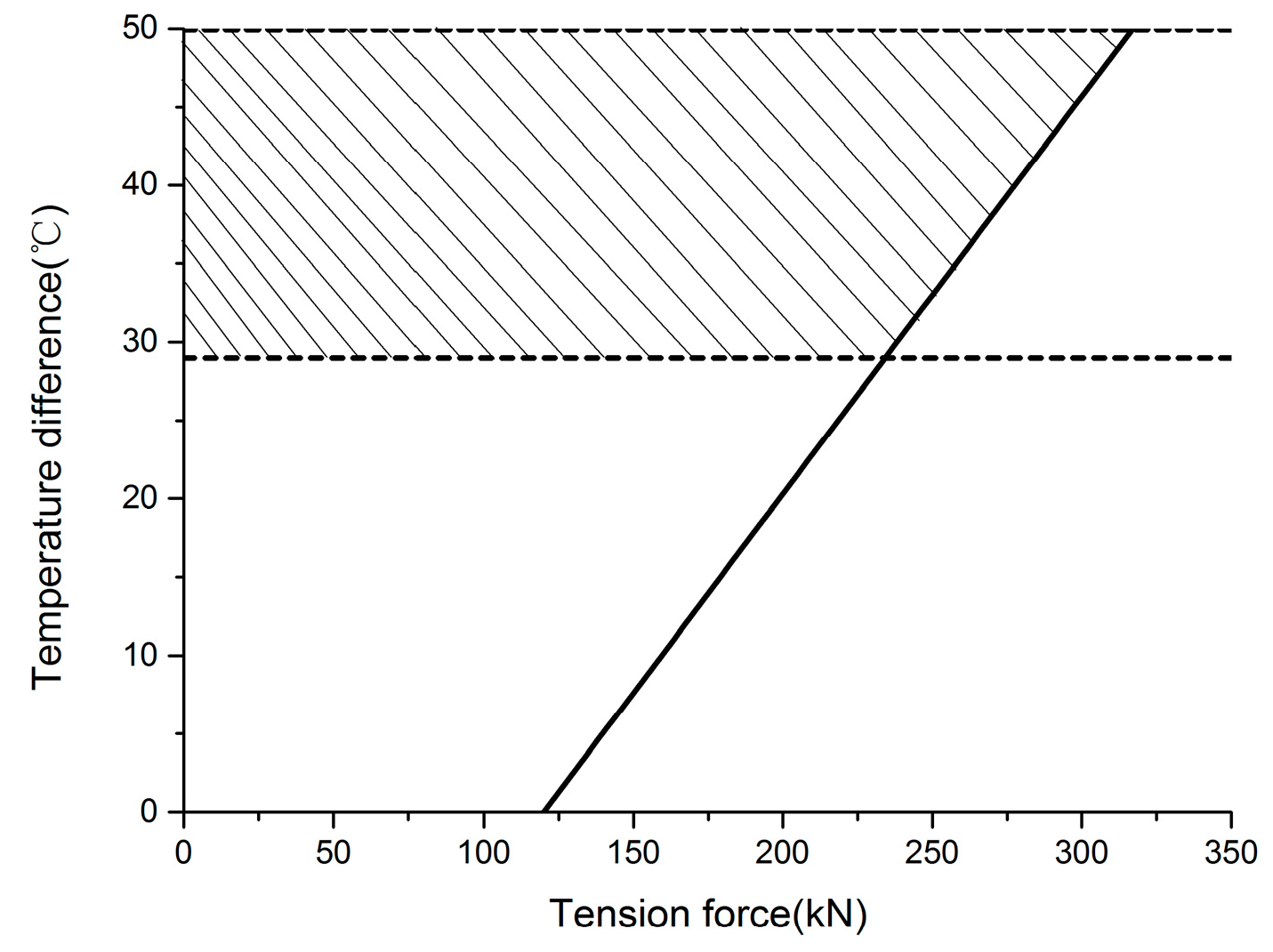
Figure 18, which is a flat surface temperature difference value under the condition of guaranteeing that the crack width and the reinforcement stress meet the design requirements of tension and temperature range, as shown in
Figure 19 (shaded area).
The maximum tensile force should not exceed 234 kN under the condition that the crack width meets the design requirements, and maximum tension force linearly increases with the rising of the reinforced concrete temperature difference. The maximum tension force should not exceed 317 kN when the reinforced concrete temperature difference value is 50 °C.
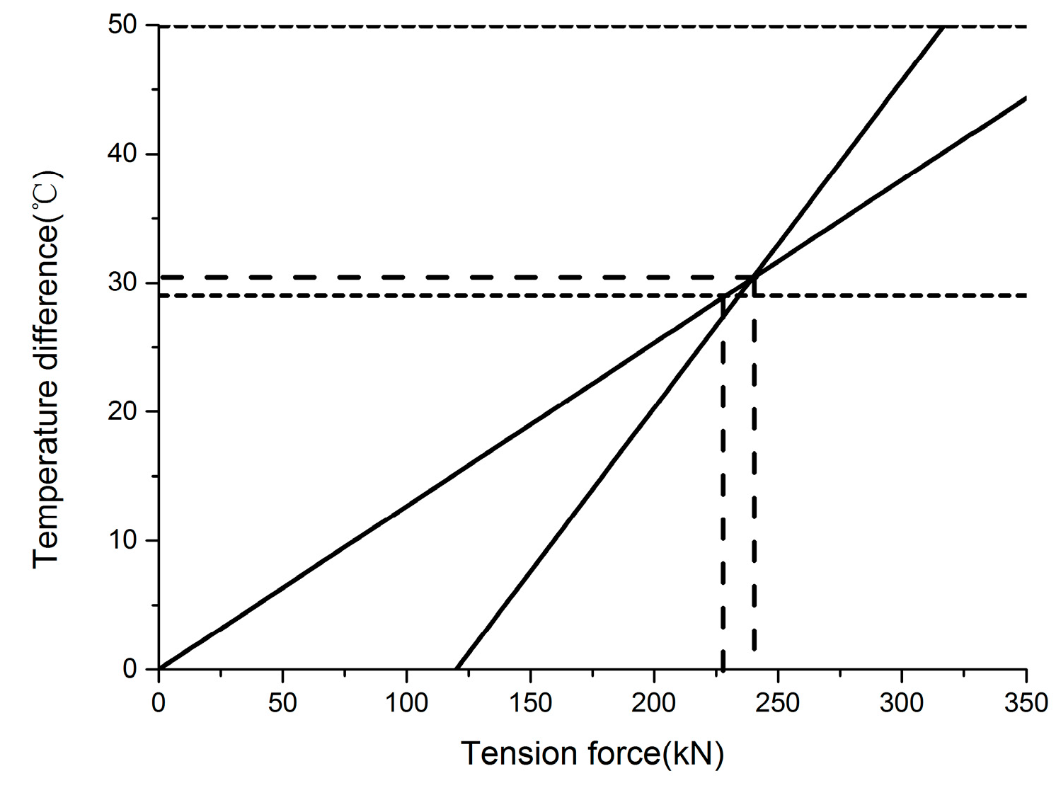
Before the casting of wide-seam concrete, the track slab is in an eccentric compression state after the longitudinal reinforcing bar is stretched, due to the existence of the narrow joint.
In order to ensure the track slab has a symmetry stress station after the casting of wide-seam concrete, the temperature increment value of the precast reinforcement should be determined according to different tensile values.
The tensile force at this point is
Figure 20 shows the relation between the tensile force value and temperature increment value of reinforcement under the condition of ensuring that the stress of reinforcement and the crack width of concrete meet the requirements and, at the same time, ensuring the tension force value of the track slab under the symmetry pressure condition. It can be seen that tension force range is 229–240 kN, and the temperature difference range is 29–30.3 °C, to meet the design requirements, and tensile force does not cause interface failure between the track slab and the mortar layer. Since the range of tension force values and the temperature difference of reinforcement are relatively small, this suggests that the tension force value should be 230 kN, and the temperature difference of reinforcement should be 30 °C for construction applications.
6. Conclusions
In this paper, a cohesive zone model was introduced in a three-dimensional finite element model of a CRTSII slab track, and utilized to investigate the damage or delamination at the interface between the track slab and CA mortar layer during the construction stage. The interface stress and damage evolution, under the conditions of different tension force values and temperature gradient loads, were analyzed. Simulation results showed that interface damage occurs under temperature gradient load at the end of the track slab because large longitudinal shear stress is produced when the tension force is greater than 300 kN. A method of applying prestress to postpouring concrete was proposed according to the concept of prestress loss of pretensioning prestressed concrete, and crack width and the reinforcement stress of the ballastless track in the operation stage were checked and calculated according to the concrete design principle. The suggested tension value is 230 kN, and the temperature difference between reinforcement and concrete value is 30 °C, before the initial curdle of concrete.
Future developments of the present work will focus on experimental verification activities in terms of applying prestressing on post concrete. A simple construction method is also needed for the operating line and for conducting on-site experiments and evaluations of this method.


