Frequency Splitting Elimination and Cross-Coupling Rejection of Wireless Power Transfer to Multiple Dynamic Receivers

 ,
,  ,
,  and
and
Abstract
:1. Introduction
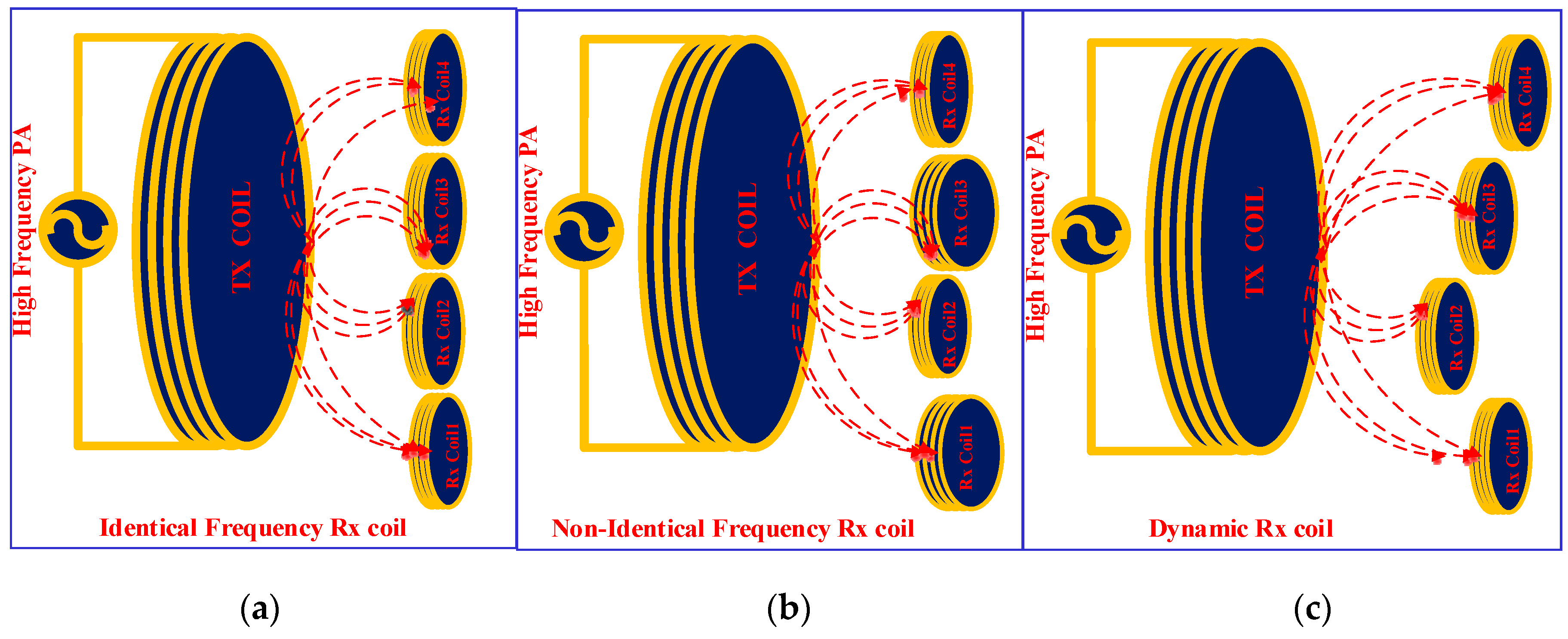
2. Dynamic Multiple Receiver
3. Performance Improvement of Multiple Receiver WPT
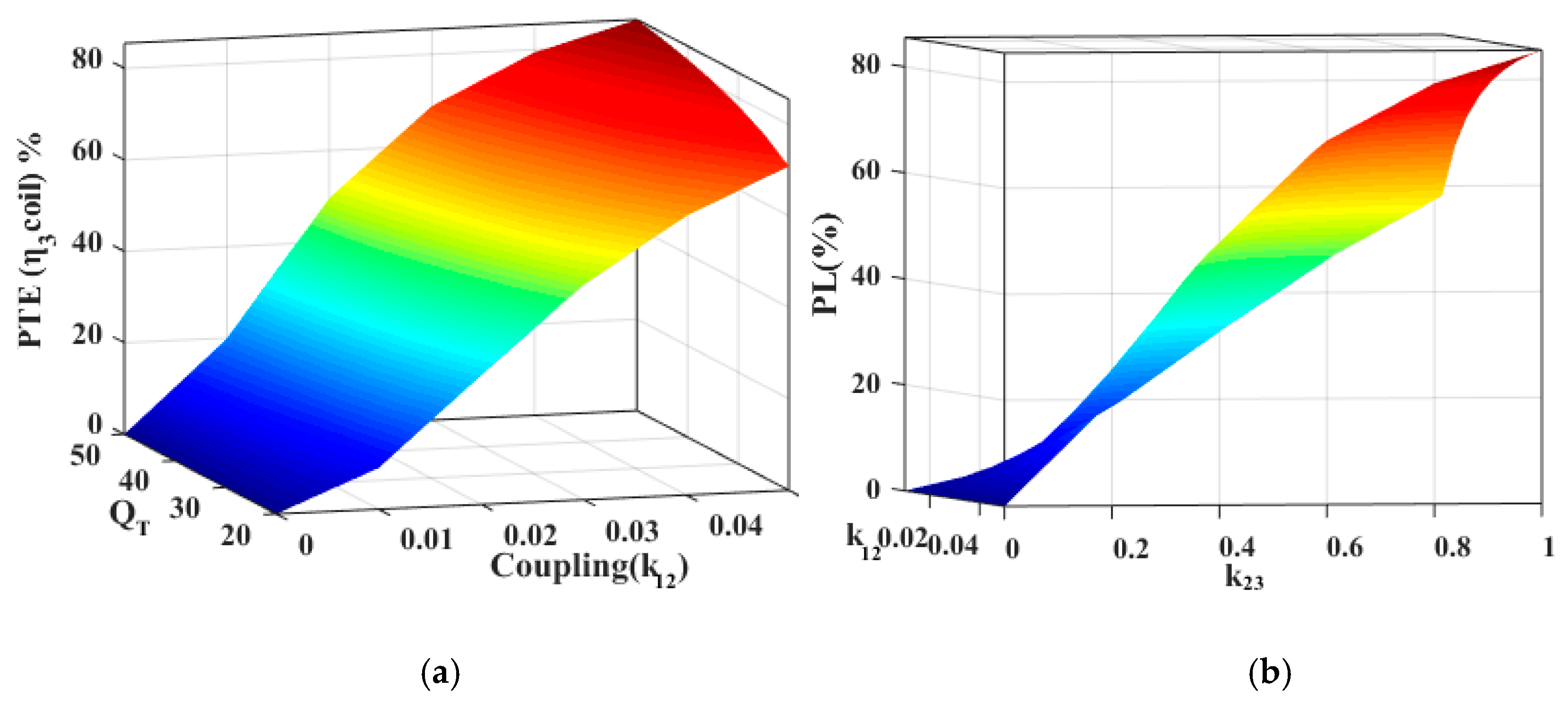
3.1. Power Transfer Efficiency Improvement
3.2. Selective MRWPT System
3.3. Cross-Coupling Rejection
3.4. Frequency Splitting Elimination
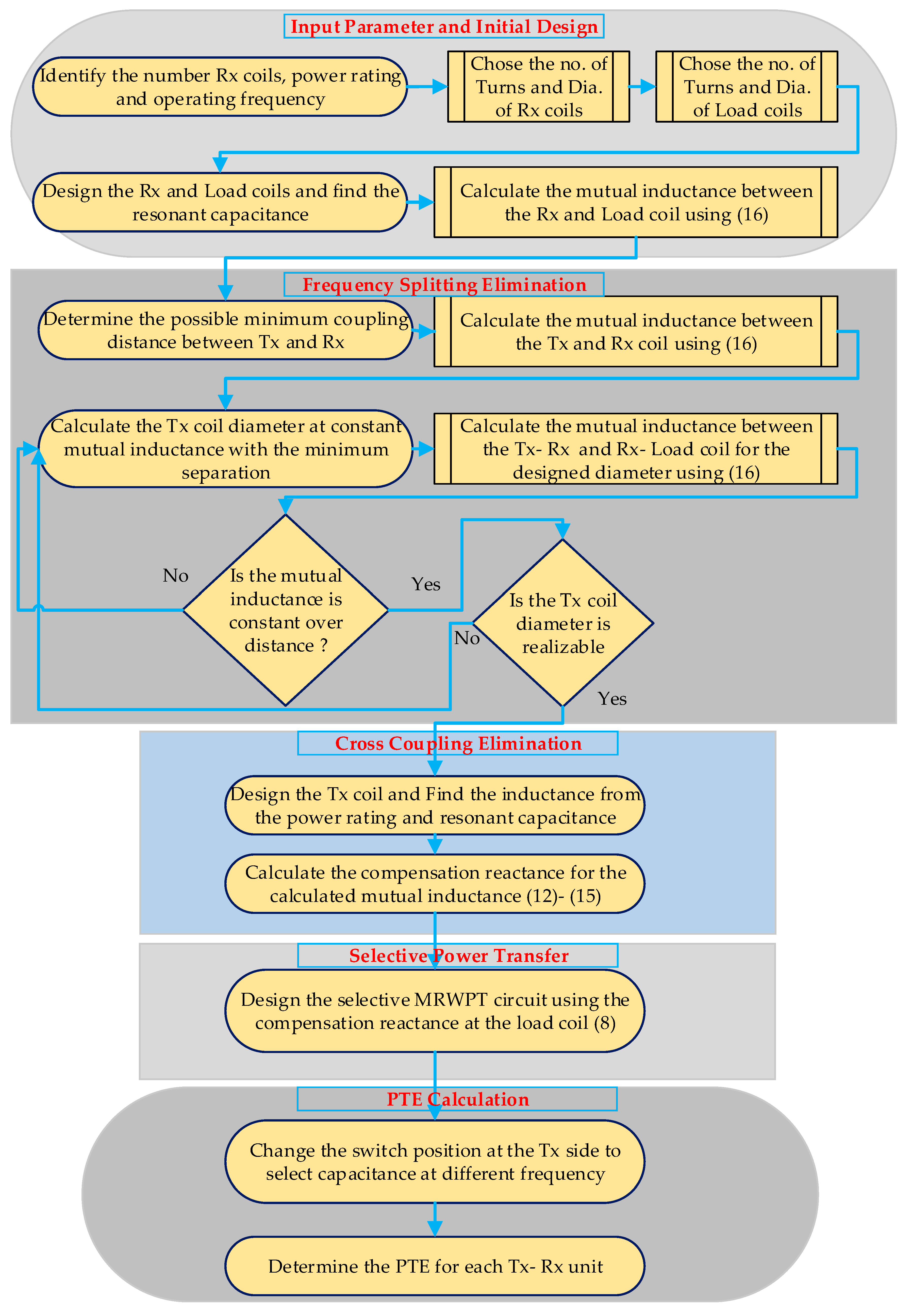
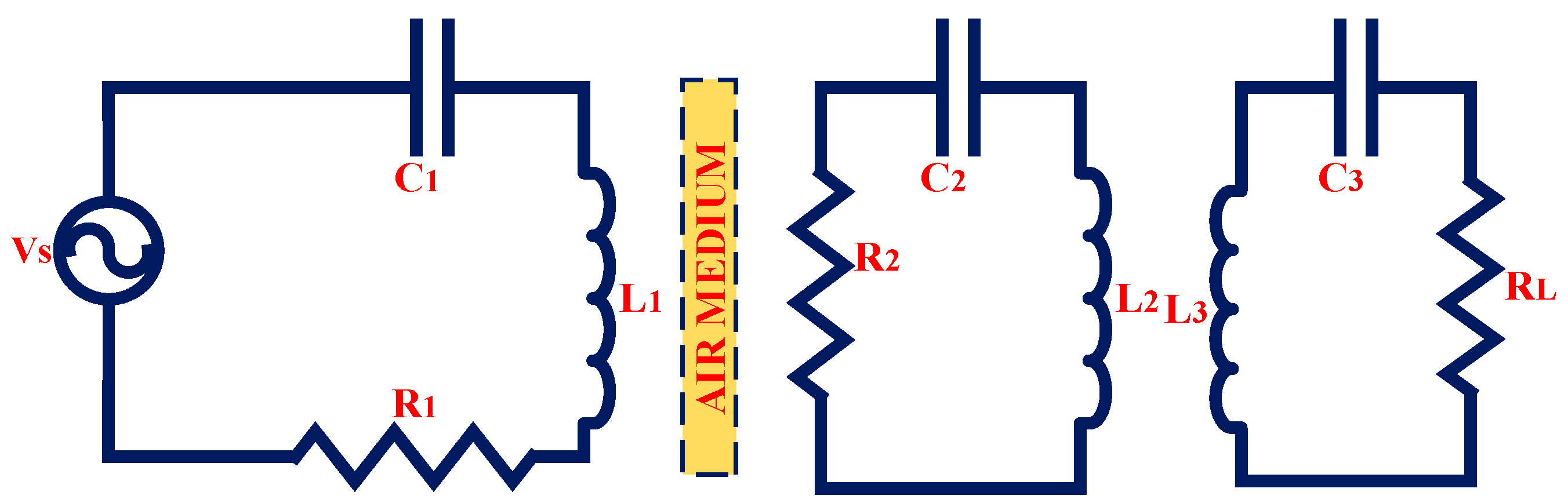
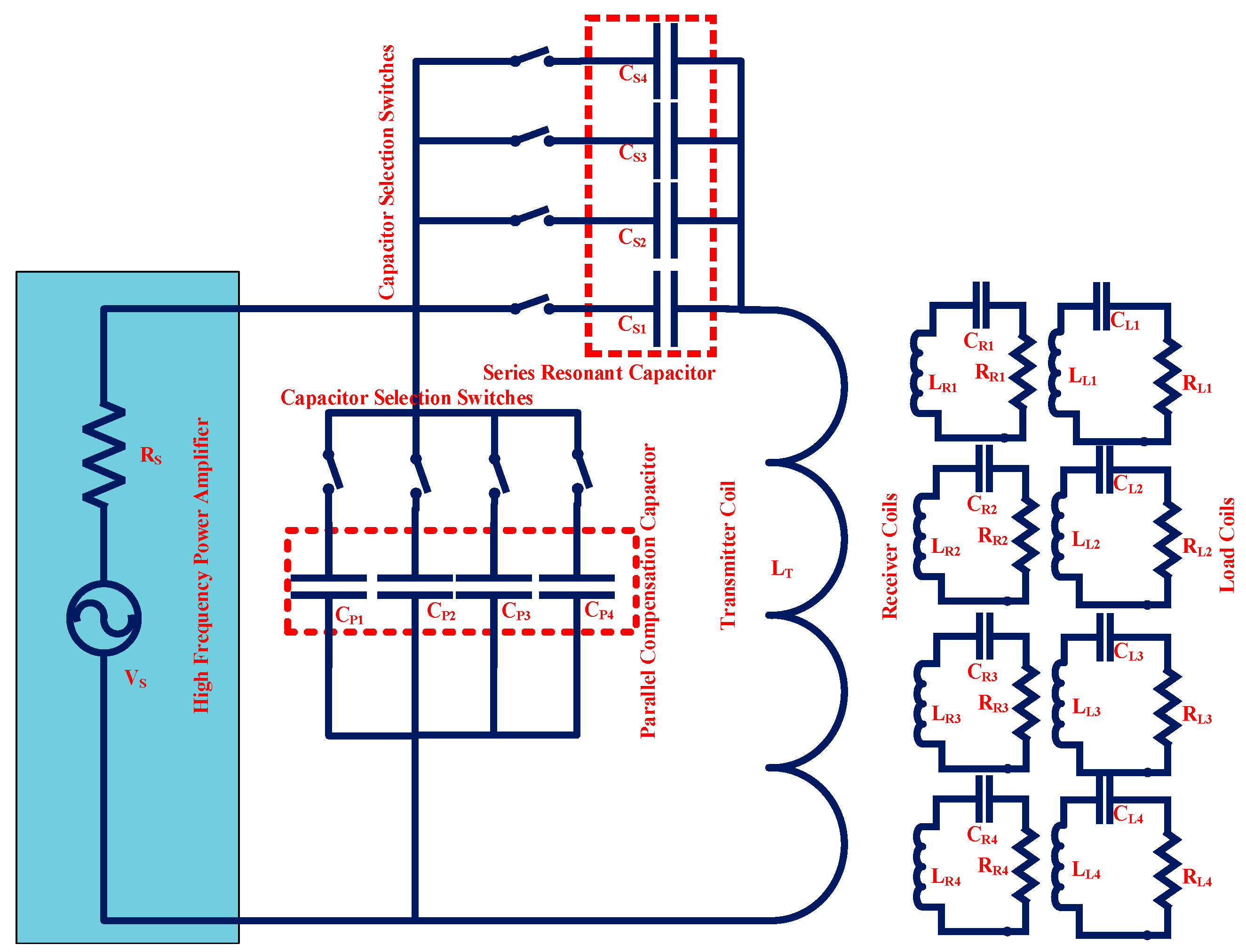
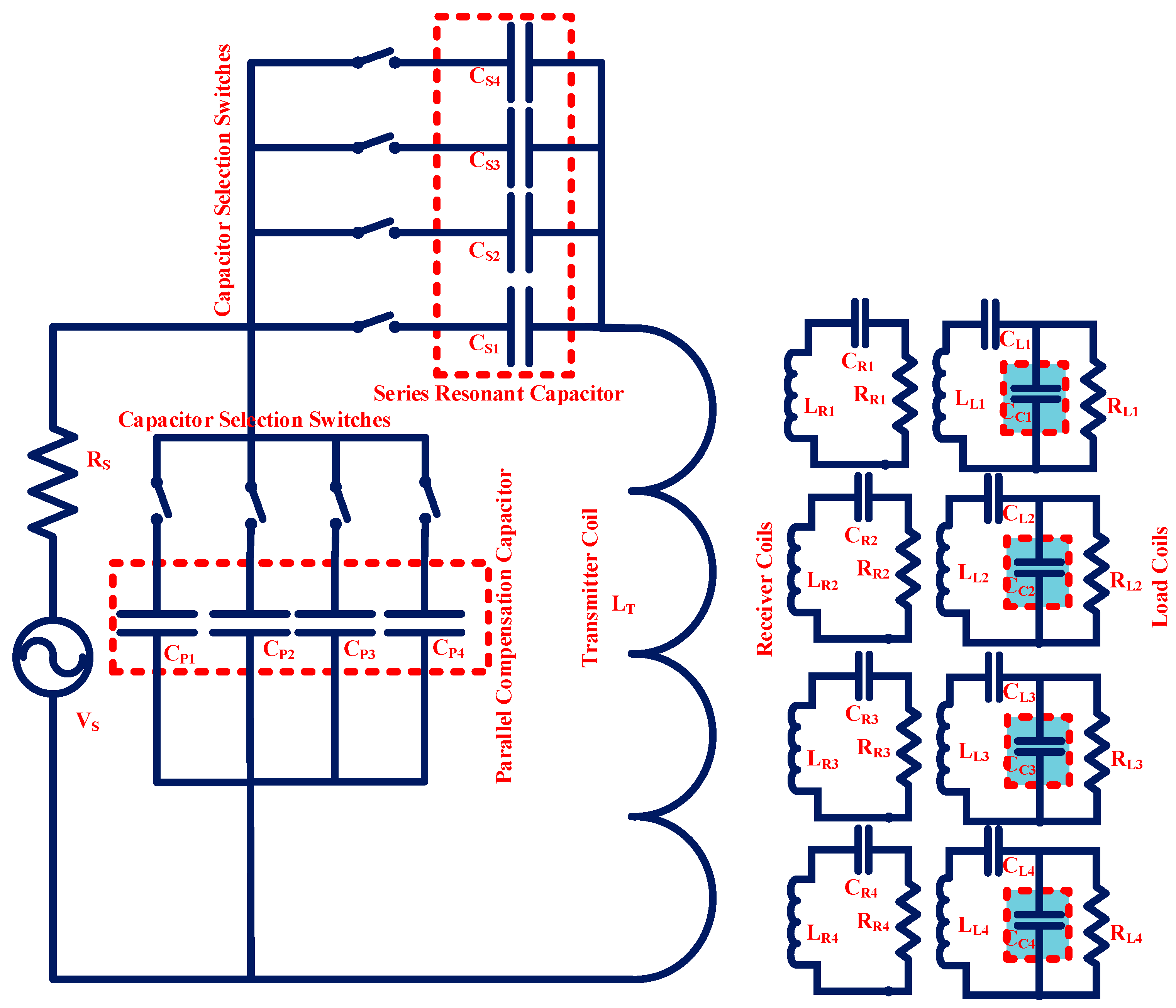
3.5. Overall System Design and Parameter Estimation
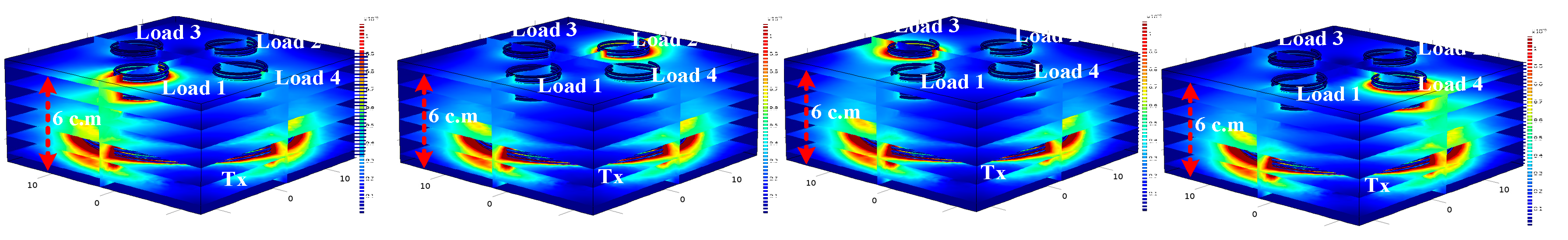
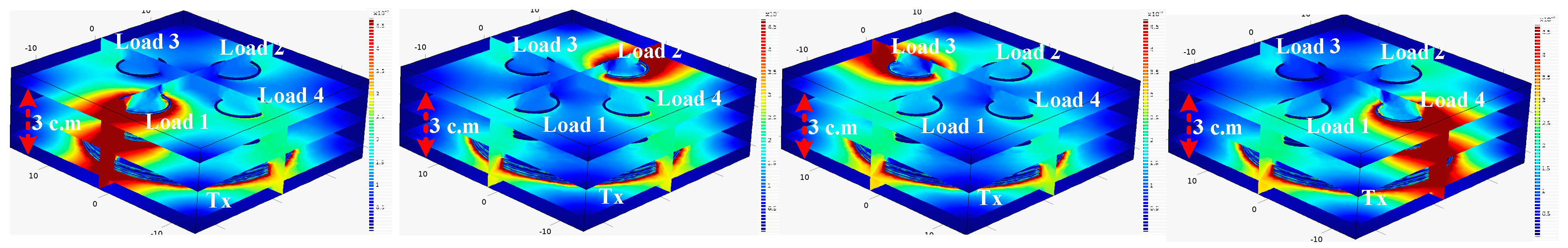
4. Finite Element Method Verification
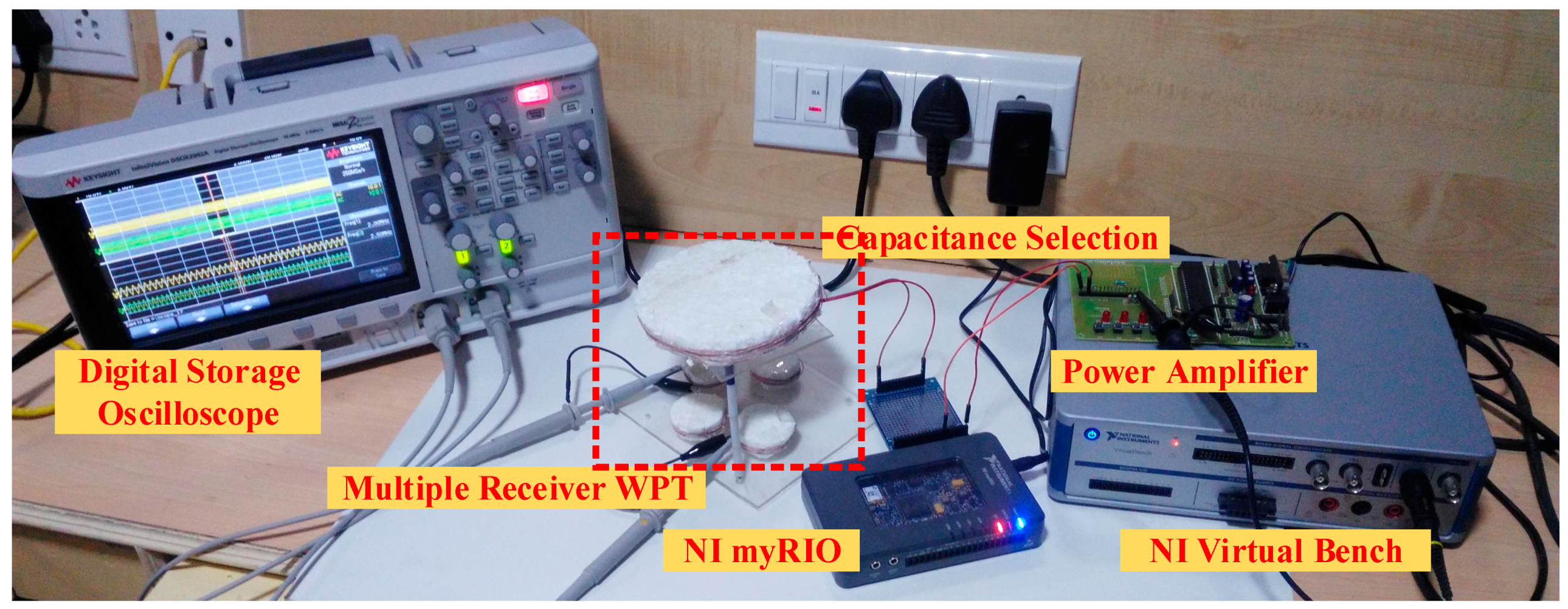
5. Experimental Verification
5.1. Selective Power Transfer at Static Load Condition
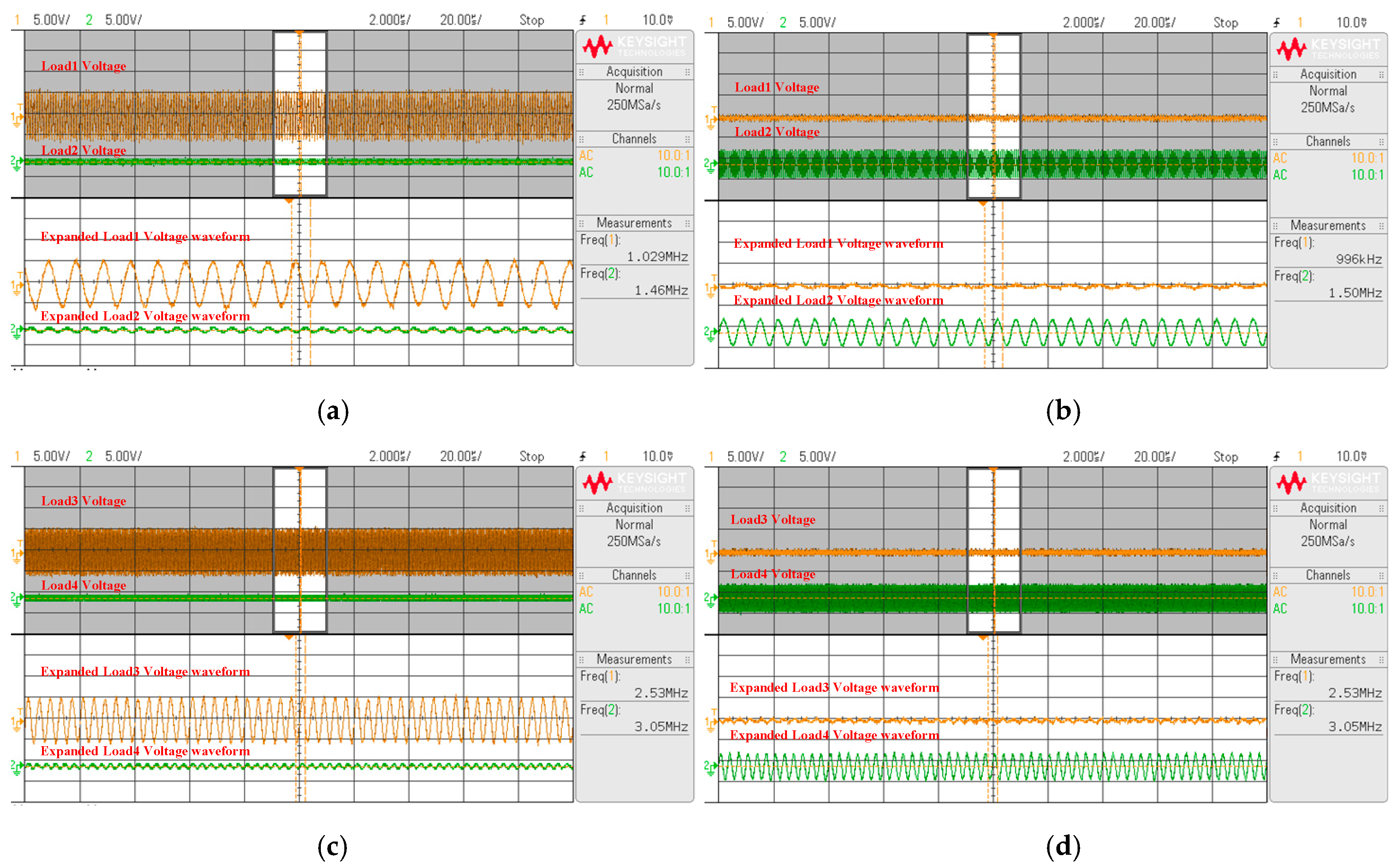
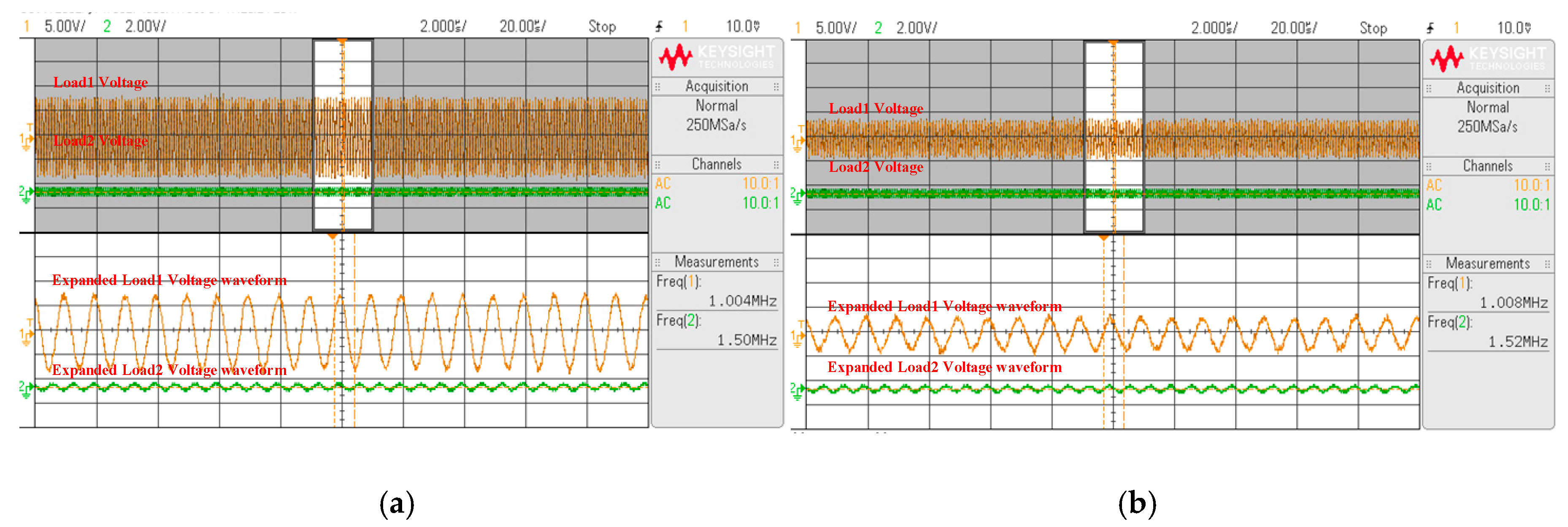
5.2. Identical Resonant Frequency Receivers
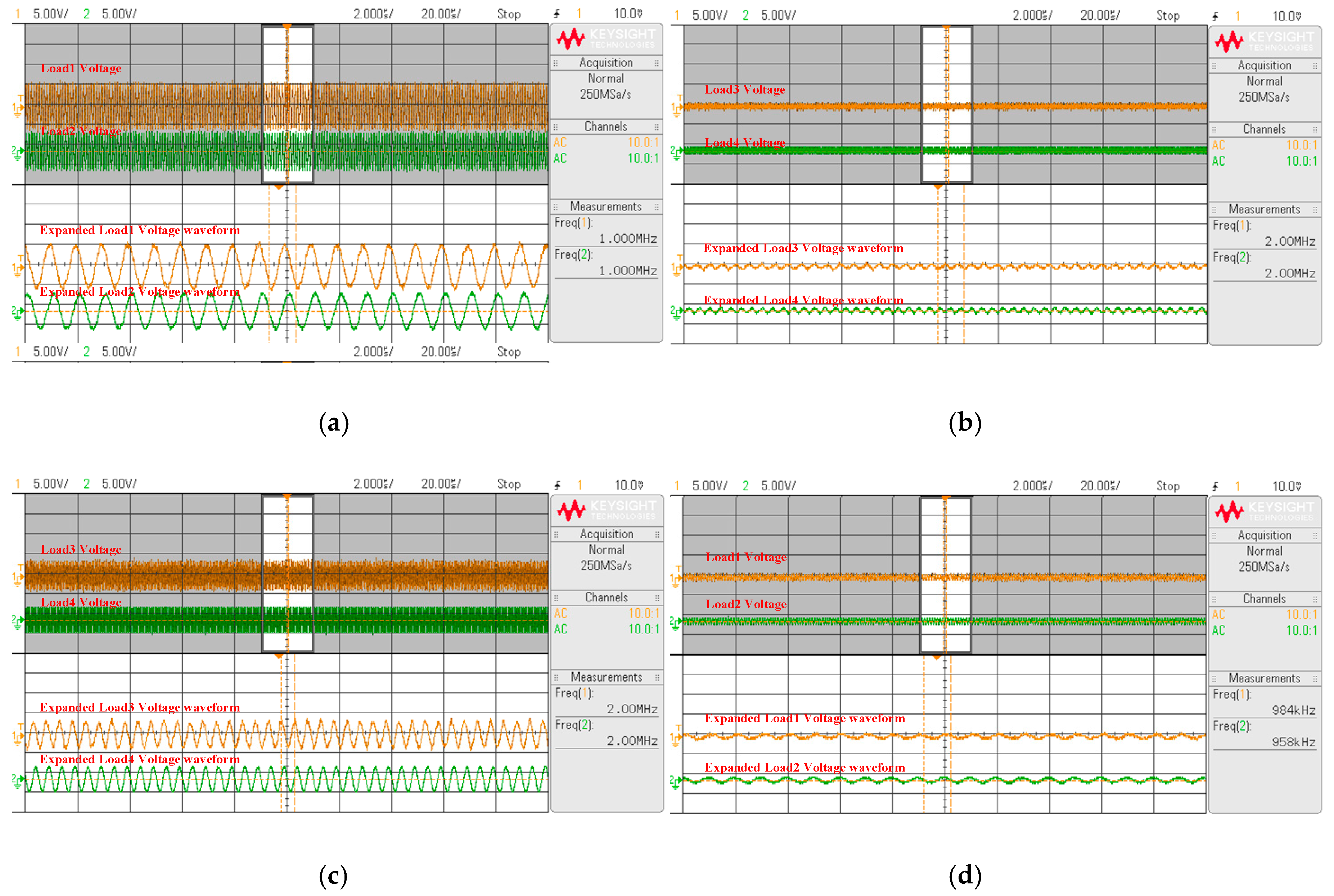
5.3. Dynamic Conditions
6. Conclusions
Author Contributions
Conflicts of Interest
References
- Jiang, C.; Chau, K.T.; Liu, C.; Lee, C.H.T. An Overview of Resonant Circuits for Wireless Power Transfer. Energies 2017, 10, 894. [Google Scholar] [CrossRef]
- Kim, J.G.; Wei, G.; Kim, M.H.; Jong, J.Y.; Zhu, C. A Comprehensive Study on Composite Resonant Circuit-based Wireless Power Transfer Systems. IEEE Trans. Ind. Electron. 2017, PP, 1. [Google Scholar] [CrossRef]
- Jawad, A.M.; Nordin, R.; Gharghan, S.K.; Jawad, H.M.; Ismail, M. Opportunities, and Challenges for Near-Field Wireless Power Transfer: A Review. Energies 2017, 10, 1022. [Google Scholar] [CrossRef]
- Huang, C.; Kawajiri, T.; Ishikuro, H. A 13.56-MHz Wireless Power Transfer System with Enhanced Load-Transient Response and Efficiency by Fully Integrated Wireless Constant-Idle-Time Control for Biomedical Implants. IEEE J. Solid-State Circuits 2017, PP, 1–14. [Google Scholar] [CrossRef]
- Narayanamoorthi, R.; Juliet, A.V.; Chokkalingam, B.; Padmanaban, S.; Leonowicz, Z.M. Class E Power Amplifier Design and Optimization for the Capacitive Coupled Wireless Power Transfer System in Biomedical Implants. Energies 2017, 10, 1409. [Google Scholar] [CrossRef]
- Dinis, H.; Colmiais, I.; Mendes, P.M. Extending the Limits of Wireless Power Transfer to Miniaturized Implantable Electronic Devices. Micromachines 2017, 8, 359. [Google Scholar] [CrossRef]
- Agarwal, K.; Jegadeesan, R.; Guo, Y.X.; Thakor, N.V. Wireless Power Transfer Strategies for Implantable Bioelectronics. IEEE Rev. Biomed. Eng. 2017, 10, 136–161. [Google Scholar] [CrossRef] [PubMed]
- Lu, Y.; Ma, D.B. Wireless Power Transfer System Architectures for Portable or Implantable Applications. Energies 2016, 9, 1087. [Google Scholar] [CrossRef]
- Ahn, D.; Mercier, P.P. Wireless Power Transfer with Concurrent 200-kHz and 6.78-MHz Operation in a Single-Transmitter Device. IEEE Trans. Power Electron. 2016, 31, 5018–5029. [Google Scholar] [CrossRef]
- Huang, S.; Li, Z.; Lu, K. Frequency splitting suppression method for four-coil wireless power transfer system. IET Power Electron. 2016, 9, 2859–2864. [Google Scholar] [CrossRef]
- Zhang, Y.; Zhao, Z.; Chen, K. Frequency-Splitting Analysis of Four-Coil Resonant Wireless Power Transfer. IEEE Trans. Ind. Appl. 2014, 50, 2436–2445. [Google Scholar] [CrossRef]
- Huang, R.; Zhang, B.; Qiu, D.; Zhang, Y. Frequency Splitting Phenomena of Magnetic Resonant Coupling Wireless Power Transfer. IEEE Trans. Magn. 2014, 50, 8600204. [Google Scholar] [CrossRef]
- Fu, M.; Yin, H.; Ma, C. Megahertz Multiple-Receiver Wireless Power Transfer Systems with Power Flow Management and Maximum Efficiency Point Tracking. IEEE Trans. Microw. Theory Tech. 2017, 65, 4285–4293. [Google Scholar] [CrossRef]
- Tan, L.; Guo, J.; Huang, X.; Wen, F. Output power stabilisation of wireless power transfer system with multiple transmitters. IET Power Electron. 2016, 9, 1374–1380. [Google Scholar] [CrossRef]
- Johari, R.; JKrogmeier, V.; Love, D.J. Analysis and Practical Considerations in Implementing Multiple Transmitters for Wireless Power Transfer via Coupled Magnetic Resonance. IEEE Trans. Ind. Electron. 2014, 61, 1774–1783. [Google Scholar] [CrossRef]
- Monti, G.; Dionigi, M.; Mongiardo, M.; Perfetti, R. Optimal Design of Wireless Energy Transfer to Multiple Receivers: Power Maximization. IEEE Trans. Microw. Theory Tech. 2017, 65, 260–269. [Google Scholar] [CrossRef]
- Tang, S.C.; Lun, T.L.T.; Guo, Z.; Kwok, K.W.; McDannold, N.J. Intermediate Range Wireless Power Transfer with Segmented Coil Transmitters for Implantable Heart Pumps. IEEE Trans. Power Electron. 2017, 32, 3844–3857. [Google Scholar] [CrossRef]
- Liu, X.; Wang, G. A Novel Wireless Power Transfer System with Double Intermediate Resonant Coils. IEEE Trans. Ind. Electron. 2016, 63, 2174–2180. [Google Scholar] [CrossRef]
- Huang, X.; Gao, Y.; Zhou, J.; Ma, J.; Zhang, J.; Fang, Y. Magnetic field design for optimal wireless power transfer to multiple receivers. IET Power Electron. 2016, 9, 1885–1893. [Google Scholar] [CrossRef]
- Lee, K.; Cho, D.H. Diversity Analysis of Multiple Transmitters in Wireless Power Transfer System. IEEE Trans. Magn. 2013, 49, 2946–2952. [Google Scholar] [CrossRef]
- Ng, W.M.; Zhang, C.; Lin, D.; Hui, S.R. Two- and Three-Dimensional Omnidirectional Wireless Power Transfer. IEEE Trans. Power Electron. 2014, 29, 4470–4474. [Google Scholar] [CrossRef] [Green Version]
- Chabalko, M.J.; Sample, A.P. Three-Dimensional Charging via Multimode Resonant Cavity Enabled Wireless Power Transfer. IEEE Trans. Power Electron. 2015, 30, 6163–6173. [Google Scholar] [CrossRef]
- Fu, M.; Zhang, T.; Ma, C.; Zhu, X. Efficiency and Optimal Loads Analysis for Multiple-Receiver Wireless Power Transfer Systems. IEEE Trans. Microw. Theory Tech. 2015, 63, 801–812. [Google Scholar] [CrossRef]
- Kim, Y.J.; Ha, D.; Chappell, W.J.; Irazoqui, P.P. Selective Wireless Power Transfer for Smart Power Distribution in a Miniature-Sized Multiple-Receiver System. IEEE Trans. Ind. Electron. 2016, 63, 1853–1862. [Google Scholar] [CrossRef]
- Cui, D.; Imura, T.; Hori, Y. Cross coupling cancellation for all frequencies in multiple-receiver wireless power transfer systems. In Proceedings of the 2016 International Symposium on Antennas and Propagation (ISAP), Okinawa, Japan, 24–28 October 2016; pp. 48–49. [Google Scholar]
- Lee, G.; Waters, B.H.; Mahoney, B.J.; Smith, J.R.; Park, W.S. An investigation of cross-coupling for magnetically coupled wireless power transfer. In Proceedings of the 2013 Asia-Pacific Microwave Conference Proceedings (APMC), Seoul, Korea, 5–8 November 2013; pp. 80–82. [Google Scholar]
- Fu, M.; Zhang, T.; Zhu, X.; Luk, P.C.K.; Ma, C. Compensation of Cross Coupling in Multiple-Receiver Wireless Power Transfer Systems. IEEE Trans. Ind. Inform. 2016, 12, 474–482. [Google Scholar] [CrossRef]
- Li, Y.; Mai, R.; Lu, L.; Lin, T.; Liu, Y.; He, Z. Analysis and Transmitter Currents Decomposition Based Control for Multiple Overlapped Transmitters Based WPT Systems Considering Cross Couplings. IEEE Trans. Power Electron. 2018, 33, 1829–1842. [Google Scholar] [CrossRef]
- Du, S.; Chan, E.; Wen, B.; Hong, J.; Widmer, H.; Wheatley, C. Wireless Power Transfer Using Oscillating Magnets. IEEE Trans. Ind. Electron. 2017, PP, 1. [Google Scholar] [CrossRef]
- Niu, W.; Gu, W.; Chu, J.; Shen, A. Frequency splitting patterns in wireless power relay transfer. IET Circuits Devices Syst. 2014, 8, 561–567. [Google Scholar] [CrossRef]
- Seo, D.W.; Lee, J.H. Frequency-Tuning Method Using the Reflection Coefficient in a Wireless Power Transfer System. IEEE Microw. Wirel. Compon. Lett. 2017, 27, 959–961. [Google Scholar] [CrossRef]
- Lyu, Y.L.; Meng, F.Y.; Yang, G.H.; Che, B.J.; Wu, Q.; Sun, L.; Erni, D.; Li, J.L.W. A Method of Using Nonidentical Resonant Coils for Frequency Splitting Elimination in Wireless Power Transfer. IEEE Trans. Power Electron. 2015, 30, 6097–6107. [Google Scholar] [CrossRef]
- Cha, H.K.; Park, W.T.; Je, M. A CMOS Rectifier With a Cross-Coupled Latched Comparator for Wireless Power Transfer in Biomedical Applications. IEEE Trans. Circuits Syst. II 2012, 59, 409–413. [Google Scholar] [CrossRef]
- Kang, S.H.; Choi, J.H.; Jung, C.W. Magnetic resonance wireless power transfer using three-coil system with single planar receiver for laptop applications. IEEE Trans. Consum. Electron. 2015, 61, 160–166. [Google Scholar] [CrossRef]
- Porto, R.W.; Brusamarello, V.J.; Müller, I.; Riaño, F.L.C.; De Sousa, F.R. Wireless power transfer for contactless instrumentation and measurement. IEEE Instrum. Meas. Mag. 2017, 20, 49–54. [Google Scholar] [CrossRef]


| Parameters | Tx | Rx1/Load1 | Rx2/Load2 | Rx3/Load3 | Rx4/Load4 |
|---|---|---|---|---|---|
| Frequency (MHz) | - | 1.0 | 1.5 | 2.0 | 3.0 |
| Inductance (µH) | 112.58 | 25.33 | 11.248 | 6.333 | 2.814 |
| Capacitance (nF) | - | 10 | 10 | 10 | 10 |
| Resistance (Ω) | 50.5 | 0.5/50.5 | 0.5/50.5 | 0.5/50.5 | 0.5/50.5 |
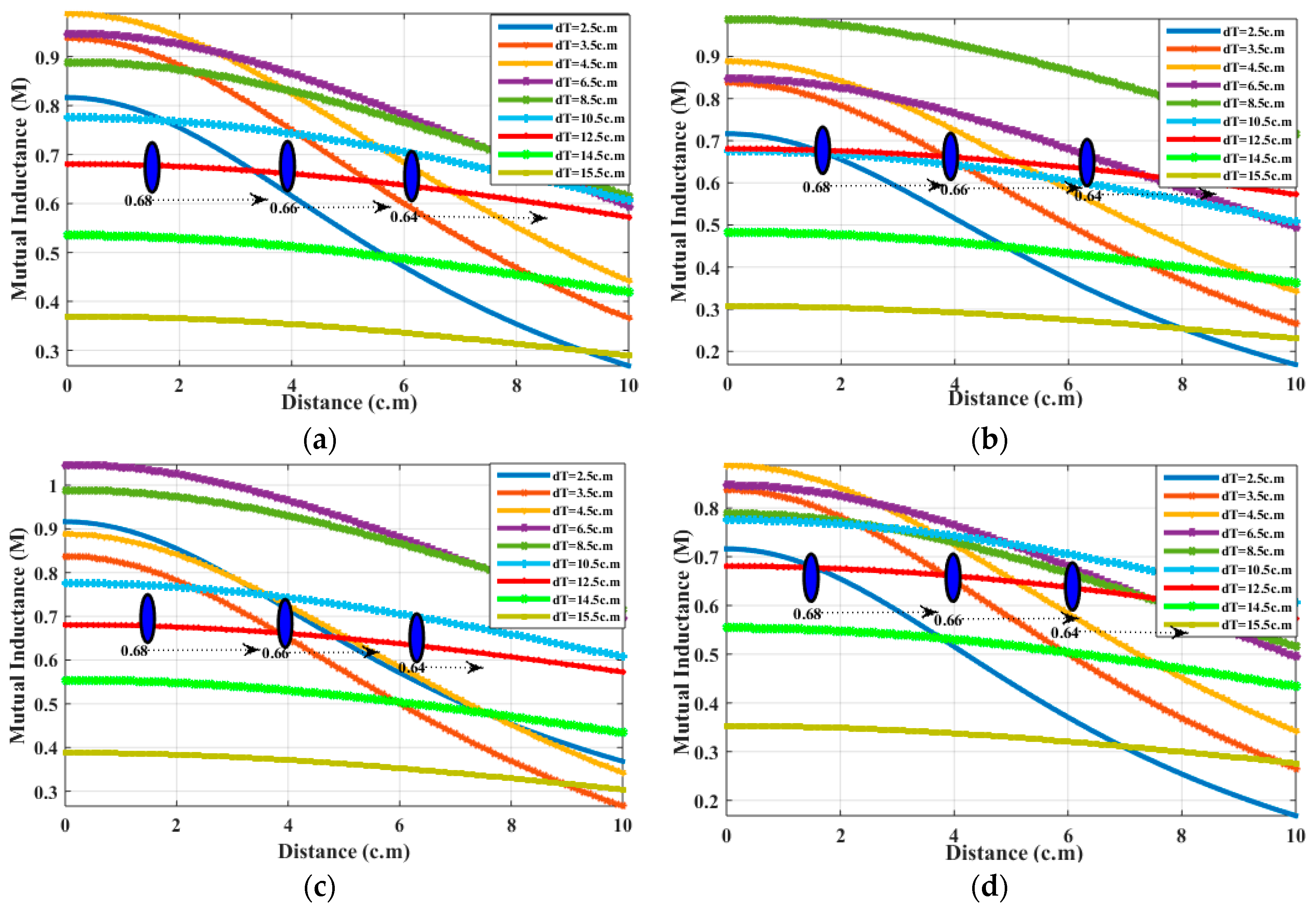
| Distance (c.m) | ||||||||||||||||
|---|---|---|---|---|---|---|---|---|---|---|---|---|---|---|---|---|
| Tx Dia (c.m) | 6.5 | 12.5 | 14.5 | 15.5 | 6.5 | 12.5 | 14.5 | 15.5 | 6.5 | 12.5 | 14.5 | 15.5 | 6.5 | 12.5 | 14.5 | 15.5 |
| 1.0 | 0.95 | 0.68 | 0.57 | 0.36 | 0.94 | 0.68 | 0.55 | 0.35 | 1.51 | 0.68 | 0.56 | 0.36 | 0.85 | 0.68 | 0.47 | 0.26 |
| 2.0 | 0.93 | 0.68 | 0.57 | 0.35 | 0.92 | 0.68 | 0.55 | 0.34 | 1.30 | 0.68 | 0.56 | 0.36 | 0.83 | 0.68 | 0.47 | 0.25 |
| 3.0 | 0.90 | 0.66 | 0.53 | 0.33 | 0.90 | 0.66 | 0.53 | 0.31 | 1.00 | 0.67 | 0.54 | 0.32 | 0.80 | 0.67 | 0.43 | 0.23 |
| 4.0 | 0.86 | 0.65 | 0.50 | 0.30 | 0.84 | 0.65 | 0.51 | 0.29 | 0.95 | 0.65 | 0.51 | 0.30 | 0.76 | 0.65 | 0.40 | 0.20 |
| 5.0 | 0.81 | 0.64 | 0.48 | 0.28 | 0.82 | 0.64 | 0.47 | 0.26 | 0.92 | 0.64 | 0.48 | 0.27 | 0.71 | 0.63 | 0.38 | 0.18 |
| 7.0 | 0.74 | 0.61 | 0.45 | 0.25 | 0.73 | 0.60 | 0.43 | 0.22 | 0.84 | 0.61 | 0.45 | 0.24 | 0.64 | 0.61 | 0.36 | 0.16 |
| 9.0 | 0.68 | 0.59 | 0.42 | 0.21 | 0.64 | 0.59 | 0.40 | 0.19 | 0.76 | 0.59 | 0.43 | 0.21 | 0.58 | 0.59 | 0.34 | 0.13 |
| 10.0 | 0.58 | 0.57 | 0.40 | 0.20 | 0.59 | 0.56 | 0.37 | 0.17 | 0.69 | 0.57 | 0.41 | 0.19 | 0.48 | 0.56 | 0.31 | 0.11 |
| Different Scenarios | Tx Coil Diameter (c.m) | Mutual Inductance | Compensating Capacitance at Tx (pF) | Compensating Capacitance at Load (pF) | |||||||||
|---|---|---|---|---|---|---|---|---|---|---|---|---|---|
| MTR1 | MTR2 | MTR3 | MTR4 | CLp1 | CLp2 | CLp3 | CLp4 | ||||||
| Scenario 1 | 12.5 | 0.68 | 0.68 | 0.68 | 0.68 | 20.2 | 9.13 | 5.72 | 2.21 | 6.71 | 8.42 | 11.23 | 14.11 |
| Scenario 2 | 12.5 | 0.63 | 0.63 | 0.55 | 0.55 | 20.2 | 9.13 | 5.72 | 2.21 | 6.42 | 8.13 | 10.45 | 13.91 |
| Scenario 3 | 12.5 | 0.68 | 0.64 | 0.55 | 0.54 | 20.2 | 9.13 | 5.72 | 2.21 | 6.71 | 8.22 | 10.45 | 13.84 |
| Scenario 4 | 12.5 | 0.61 | 0.66 | 0.59 | 0.51 | 20.2 | 9.13 | 5.72 | 2.21 | 6.32 | 8.36 | 11.11 | 13.31 |
| Parameters | Tx | Rx1/Load1 | Rx2/Load2 | Rx3/Load3 | Rx4/Load4 |
|---|---|---|---|---|---|
| Diameter (c.m) | 12.5 | 4.5/4.5 | 4/4 | 3.5/3.5 | 3/3 |
| Number of turns | 08 | 10 | 8 | 8 | 6 |
| Compensation capacitance (pF) | - | 6.71 | 8.42 | 11.23 | 14.11 |
| Wire AWG | 30 | 30 | 30 | 30 | 30 |
| Methods of Reference | No. of Tx | No. of Rx | No. of Relay | (MHz) | Remarks |
|---|---|---|---|---|---|
| Multiple Rx, Multiple Tx [15] | 2 | 2 | 0 | 1 MHz | Requires two Tx and analyzed under static condition |
| Selective Power Transfer [24] | 1 | 3 | 0 | 21.5 MHz to 23.5 MHz | Suitable for uniform power transfer and cross-coupling issue for identical Rx’s |
| Cross-Coupling Elimination [27] | 1 | 3 | 0 | 1 MHz | The uniform power distribution and frequency splitting elimination is not achieved |
| Dynamic Rx WPT [20] | 1 | 3 | 0 | 1 MHz | The cross-coupling and frequency splitting is not addressed |
| This Work | 1 | 4 | 1 | 1 MHz to 3 MHz | The cross-coupling, frequency splitting issue is addressed with selective power transfer |
© 2018 by the authors. Licensee MDPI, Basel, Switzerland. This article is an open access article distributed under the terms and conditions of the Creative Commons Attribution (CC BY) license (http://creativecommons.org/licenses/by/4.0/).
Share and Cite
R., N.; Juliet, V.; Padmanaban, S.; Mihet-Popa, L.; C., B. Frequency Splitting Elimination and Cross-Coupling Rejection of Wireless Power Transfer to Multiple Dynamic Receivers. Appl. Sci. 2018, 8, 179. https://doi.org/10.3390/app8020179
R. N, Juliet V, Padmanaban S, Mihet-Popa L, C. B. Frequency Splitting Elimination and Cross-Coupling Rejection of Wireless Power Transfer to Multiple Dynamic Receivers. Applied Sciences. 2018; 8(2):179. https://doi.org/10.3390/app8020179
Chicago/Turabian StyleR., Narayanamoorthi, Vimala Juliet, Sanjeevikumar Padmanaban, Lucian Mihet-Popa, and Bharatiraja C. 2018. "Frequency Splitting Elimination and Cross-Coupling Rejection of Wireless Power Transfer to Multiple Dynamic Receivers" Applied Sciences 8, no. 2: 179. https://doi.org/10.3390/app8020179