Bio-Inspired Optimal Control Framework to Generate Walking Motions for the Humanoid Robot iCub Using Whole Body Models


1
Optimization, Robotics & Biomechanics, Institute of Computer Engineering (ZITI), Heidelberg University, Berliner Str. 45, 69120 Heidelberg, Germany
2
Interdisciplinary Center for Scientific Computing (IWR), Heidelberg University, INF205, 69120 Heidelberg, Germany
*
Author to whom correspondence should be addressed.
Appl. Sci. 2018, 8(2), 278; https://doi.org/10.3390/app8020278
Submission received: 16 November 2017
/
Revised: 19 January 2018
/
Accepted: 6 February 2018
/
Published: 12 February 2018
(This article belongs to the Special Issue Bio-Inspired Robotics)
Abstract
:Bipedal locomotion remains one of the major open challenges of humanoid robotics. The common approaches are based on simple reduced model dynamics to generate walking trajectories, often neglecting the whole-body dynamics of the robots. As motions in nature are often considered as optimal with respect to certain criteria, in this work, we present an optimal control-based approach that allows us to generate optimized walking motions using a precise whole-body dynamic model of the robot, in contrast with the common approaches. The optimal control problem is formulated to minimize a set of desired objective functions with respect to physical constraints of the robot and contact constraints of the walking phases; the problem is then solved with a direct multiple shooting method. We apply the formulation with combinations of different objective criteria to the model of a reduced version of the iCub humanoid robot of 15 internal DOF. The obtained trajectories are executed on the real robot, and we carry out a discussion on the differences between the outcomes of this approach with the classic approaches.
1. Introduction
Humanoid robots have been designed and built for decades, inspired by nature and in particular human structure and behavior. The goal is to use humanoid robots in environments that are made for and populated by humans, either supporting the human in his/her activities if they are too heavy or too boring, or replacing him/her in situations that are too dangerous. Furthermore, replacing humans with respect to work in a space is a common target for humanoid robotics. Therefore, there is a general expectation that humanoid robots should be able to perform the same tasks and have the same motion capabilities as humans and, in the future, even outperform humans in these tasks.
Ever since the first appearance of humanoid robots, many of them have been equipped with legs. However, the bipedal locomotion capabilities of these robots are still far behind what humans are able to perform. To date, walking remains one of the major open challenges of bipedal humanoid robotics. The difficulty of achieving stable, dynamic and versatile walking for bipedal robots is due to many reasons: the anthropomorphic shape of the humanoid robot exhibits a high redundancy with respect to most motion tasks, but at the same time, it is also difficult to determine feasible solutions, since many of the joint angle combinations result in infeasible motions. Humanoids are generally underactuated with no direct actuators for the overall position and orientation in space, which have to be moved instead by a coordinated action of many other actuators considering feasibility. It should be noted that for most current humanoid robots, a typical human walking behavior is much too challenging in terms of speed, joint motion ranges, required torques and impacts. Humanoid locomotion also involves changing contacts with the environment, which have to be properly chosen. Stability control of humanoid locomotion is one of the biggest problems, since bio-inspired bipedal walking cannot be performed in a statically stable way, but must be dynamically stable. The precise definition of dynamic stability of human walking is still unknown, and up to now, many humanoid robots still apply the well-known Zero Moment Point (ZMP) criterion [1] instead, which is very convenient to use, but results in more conservative gaits.
Motion generation for humanoid robots can be divided into two main categories: motion remapping and model-based generation. In the first case, walking motions from humans are recorded via motion capturing systems, then they can be transferred to the robot by taking into account robot specific constraints such as physical constraints and stability criteria. The recorded motions can be first processed as motion primitives and then concatenated to generate complex motions, such as achieved on the robot HRP-2 (Humanoid Robotics Projects, Kawada) [2], or directly transferred to the robot by means of reduced models and adjustments of end effector positions, as achieved on the JAXON and CHIDORI robots [3]. In the case of model-based motion generation, the most common method is to use reduced models together with the ZMP criterion. Reduced models are for example the Linear Inverted Pendulum (LIPM) [4] or the table cart [5], which allowed many robots to achieve stable walking, such as on HRP-2 [6], by means of Nonlinear Model Predictive Control (NMPC), on the compliant humanoid robot CoMan [7] and iCub [8]. In all these cases, the whole-body posture is computed by means of inverse kinematics matching the desired end effector positions computed with the dynamics of the reduced models. The main reason for which reduced models are still widely used is because they allow for fast online control. However, it is known that due to the many assumptions that are introduced due to the use of such models, the whole-body dynamics of the robot is not well exploited, and the motions often appear over-constrained and not very natural.
Another, more bio-inspired way of motion generation is to use optimization, or to be more precise, optimal control, based on whole-body models of the robots. Optimality is often considered to be a guiding principle of nature, and movements that are performed frequently such as everyday motions or trained motions tend to be optimal with respect to some optimality criterion. By the use of mathematical optimization in the generation of motions for humanoid robots, this biological optimization process is mimicked. The optimization criteria used can be either biologically inspired (by analyzing the optimality criteria of humans or other biological systems, e.g., by inverse optimal control [9]), or technically motivated. In addition, optimization helps to solve the feasibility and the redundancy issues of walking. It generates motions that are feasible with respect to all constraints that can be formulated in a detailed whole-body model of the robot and of the motion task. From all redundant solutions of a particular task, it selects the one that is optimal with respect to the chosen optimization criterion. In addition, optimization techniques can be used to kinematically adjust humanoid motions to recorded human motions, taking the different geometry into account (see, e.g., [10]). See [11] for a general overview of optimization in the context of humanoids.
Optimal control has previously been used to generate challenging motions using whole-body models for robots such as HRP-2 [12,13,14,15,16,17,18]. In an approach that is situated between whole-body optimization and motion generation by reduced models, optimization of template models has been used for generating walking motion of humanoid robots in challenging scenarios [19]. Collocation has been a popular method to compute walking motions for humanoid robots using whole-body models and contact constraints, such as in [20,21], where motions could be obtained in a time in the range of minutes to hours.
In previous works, we have achieved the first walking motions on one of the most disseminated complex humanoid robots iCub [22], by means of the table cart model and ZMP criterion [8], allowing the robot to achieve walking on level ground and, for the first time, on slopes and stairs, with the aim of measuring the walking capabilities of iCub. In particular, this work has been performed on the reduced version of the iCub available in our lab with neither head and arms (named the HeiCub (iCub of Heidelberg University)), but the results are transferable to the full iCub models. We later improved the walking performances by means of a closed-loop control scheme based on NMPC, which allowed the robot to be able to change walking directions online [23].
In this work, instead, we want to use the whole-body dynamic model of the robot to generate walking motions on level ground. Similar to the setup of the problem for HRP-2 in [15], here, we formulate the optimal control problem for walking using the detailed model of the the humanoid robot iCub/HeiCub. In the optimal control problem, we set several objective functions and constraints to describe the hybrid dynamics of walking and to respect the physical constraints of the robot itself. In contrast to [20,21], the problem is solved using a direct multiple direct shooting method [24], which allows obtaining precise and accurate results and has been used previously to obtain open-loop stable robot motions [25]. The obtained motions are then transferred to the robot, and the outcomes are discussed with a comparison with the motions we had previously achieved on the same robot with reduced models. The main contributions of this paper consist of:
- Formulation of the whole-body dynamic model for walking problems for the humanoid robot iCub.
- Formulation of the optimal control problem for a complex walking sequence involving cyclic, as well as non-cyclic motion phases.
- The use of a direct multiple shooting method, which allows solving the equations of motion at a high precision at all times in the gait and to precisely take into account the kinematic and dynamic constraints of the robot.
- Implementation and experimental validation on the HeiCub humanoid, a reduced iCub, with computation of performance indicators as a comparison with motions generated using reduced models.
This paper is organized as follows: In Section 2, we give a description of the iCub humanoid robot and its reduced version HeiCub. Section 3 describes in detail the different walking phases involved in the optimal control problem, as well as the dynamics equations in all cases. In Section 4, we illustrate the optimal control problem formulation giving the details of states, controls, parameters, objective functions and constraints. Section 5 shows the numerical results and the software tools used, followed by the experimental results obtained on the robot in Section 6. The paper concludes in Section 7 with a final discussion of the work and conclusions, as well as possible future developments.
2. The (He)iCub Humanoid Robot
The iCub [22] is a humanoid robot designed and built by the Fondazione Istituto Italiano di Tecnologia (IIT) and distributed among more than 30 research institutions and universities all over the world. The robot was originally designed with the aim of conducting cognitive studies; therefore, it was meant to resemble a 3–4-year-old child. The latest version of the robot consists of a whole-body humanoid with head, arms and legs, for a total of 53 degrees of freedom (DOF), including dexterous hands.
The iCub is mostly known for its grasping [26,27] and balancing [28] capabilities, which have been widely exploited by several works in past and recent years, while in the first versions of iCub, the robot legs had weak actuators and small feet that did not allow the robot to perform walking, but only crawling. In the latest available version, the legs have been redesigned [29] inspired by the mechanical design of the CoMan humanoid robot, which has demonstrated several walking capabilities [30,31,32].
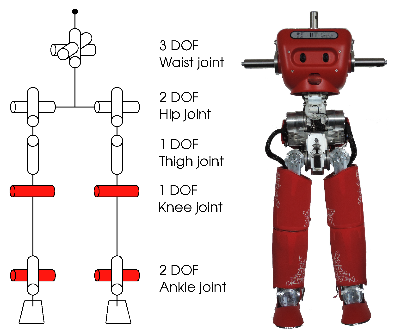
In the context of the European Project KoroiBot, IIT has delivered to Heidelberg University a reduced version of the standard iCub, consisting of 15 internal DOF: three in the torso and six in each leg, as shown in Figure 1. The robot is furthermore equipped with four Force Torque sensors (F/T), two in the upper legs and two in the feet. The robot has an on-board PC104 with a dual core, but has no battery; therefore, it needs to be connected to an external power supply by means of cables, which serve also as network communication cables, allowing one to use external computers to carry out bulky computations. The robot has also four custom Series Elastic Actuators (SEA) [33] with springs that can be unmounted to obtain rigid actuators. In the context of this paper, the springs are unmounted, and therefore, the joints are considered perfectly rigid.
The robot has a weight of 26.4 kg, and it is 0.97 m tall. The leg length from the hip axis is 0.51 m, and the feet are 0.2 m long and 0.1 m wide. The weight distribution of the robot is about 6 kg for the torso, 5 kg for the pelvis and 7.5 kg each leg. All the kinematic and dynamic parameters of the robot are described in a URDF (Unified Robot Description Format) file, which was extracted directly from the original CAD model. The hardware limitations, including joint limits, joint velocity limits and torque limits, are as in Table 1. Please note that the velocity and torque limits have been obtained via experiments; therefore, they are not perfectly precise, i.e., these limits might be conservative, as they are set to guarantee the safety of the robot.
To distinguish this robot from the standard iCub, we will use the name HeiCub (iCub of Heidelberg University) to refer to it from now on. The legs of HeiCub have the exact same mechanical design as any other standard iCub, and it also uses the same software infrastructure as the iCub. These features allow us to transfer control frameworks developed for the iCub to HeiCub and vice versa, by just adapting the number of DOF and the upper body structure.
3. Model and Dynamics
As during walking, different contacts are involved, we define walking as a hybrid dynamics system, where the dynamics switches according to contact conditions, i.e., hybrid and non-smooth dynamics. To have a precise description of the dynamics of walking, in the following, we first list the phases that involve the different contacts and then the dynamics equations that will be used in the optimal control problem.
3.1. Walking Phases
Different phases can be identified for a walking sequence. This is usually done also for human walking motion analysis [34], where the different feet contacts are described and the phases might change according to the walking environment [35]. Differently from humans, HeiCub has a rigid flat foot, common among humanoid robots. Therefore, the walking phases for such a humanoid are different from human walking, as we have to consider completely flat contacts between the feet and the ground.
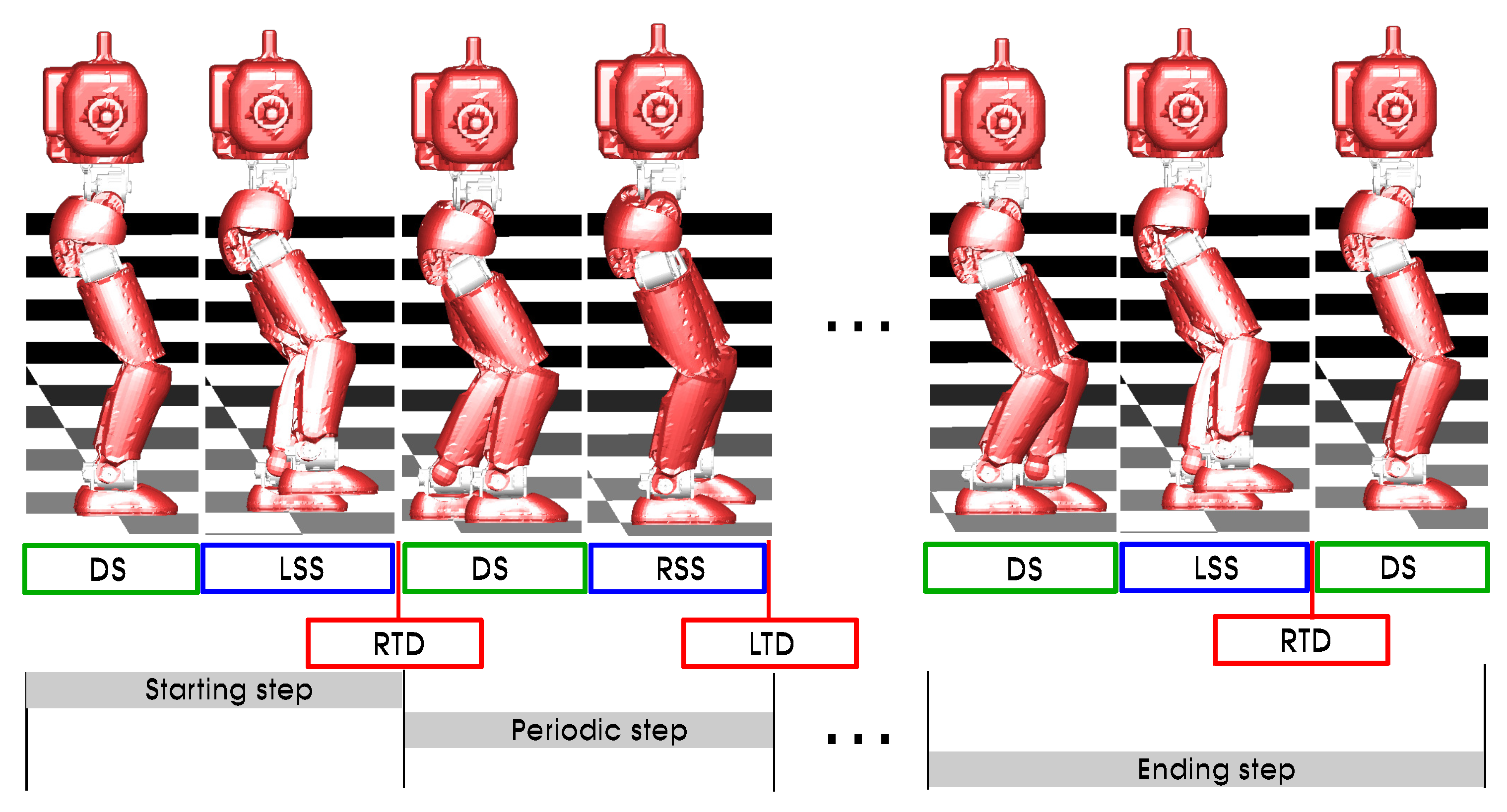
As shown in Figure 2, the walking sequence can be seen as three sub-sequences:
- Starting step, the robot starts from a complete stop (i.e., all velocities to zero) and takes the first step, leading to the periodic motion.
- Periodic steps, which are the steps that the robot can repeat during walking. In this case, we assume single-step periodic, i.e., the left and right leg configurations can be mirrored, as the robot is symmetric. The periodicity is enforced on touchdown.
- Ending step, the final step where the robot comes to a complete stop from the periodic motion.
It is to be noted that in this case, we assume that one step is enough to lead the motion into a periodic motion and to lead the motion to an end. This assumption might not be valid for every system and situation; however, we have verified that in the cases we considered for HeiCub in this paper, this assumption can be used. A further discussion is carried out in Section 7.
The walking phases involving different contacts are described as follows:
- DS: Double Support, where both feet are on the ground.
- LSS: Left Single Support, where the left foot is on the ground and the right leg swings to the next support location.
- RSS: Right Single Support, as for LSS, the right foot is on the ground and the left leg is swinging.
In addition, there are also two impacts that follow each of the single-support phases and precede the double-support phases:
- RTD: Right Touch Down, when the left foot is in single support and the right foot strikes the ground, we assume that when the foot of the robot touches the ground, it is completely flat.
- LTD: Left Touch Down, the left foot strikes the ground when the right foot is in single support.
To define a flat contact, it is enough to define three contact points on each of the feet, as shown in Figure 3.
Given the description of the walking phases, we illustrate in the following the dynamics equations based on few assumptions.
3.2. Dynamics
The robot is described with the generalized coordinates , where , with 15 internal DOF and six external DOF describing the floating base, with three translations along and three rotations about the same axis represented with Euler angles.
The dynamics of a rigid multi-body system such as a robot can be described by the equations of motion:
where the matrix is the joint space inertia matrix, is the joint acceleration vector, the Coriolis, centrifugal and gravitational term and are the joint torques. Given that the robot is a floating base system, the vector of joint torques is assumed to be:
where is the vector of active joint torques.
We introduce the following set of constraints due to contacts:
which depend on the walking phases, as previously described.
In our formulation, we assume that contacts are perfectly rigid and non-sliding and impacts are instantaneous and inelastic. Therefore, taking into account (3) in (1), we obtain:
where is the vector of external forces due to the contacts and is the contact Jacobian.
An additional set of equations for the contact constraints is obtained by differentiation twice of Equation (3):
Combining Equations (4) and (5), we obtain the following system of equations for unknown and :
where . This system describes the dynamics of the continuous phases of single and double supports, i.e., DS, LSS and RSS. In the case of DS, the number of contacts is six, i.e., both feet have flat contacts with the ground, while in the case of LSS and RSS, the number of contacts is three, i.e., only one foot has flat contact with the ground.
Due to the assumptions on the impacts, the dynamics describing the instantaneous change in the generalized velocities can be obtained by integrating Equations (4) and (5) over a time singleton. The following system of equations can be written for the unknown generalized velocities after the impact and the impulses at each constraint :
where are the generalized velocities before the impact, and the desired velocity of contact points after the impact, which is due to the previously-described assumptions. The system as in Equation (7) describes the dynamics of the impacts LTD and RTD as in Figure 2.
4. Optimal Control Problem
The optimal control problem is formulated to treat the hybrid dynamic system described in the previous section; therefore, it results in a multiple-phase optimal control problem, where each of the phases are as described in Figure 2.
The general formulation of a multiple phases optimal control problem can be described as follows:
subject to:
In the problem formulation, objective functions of Lagrangian type and/or Mayer type are minimized with respect to the states , the controls and the model parameters . These objective functions can be different for each phase, as described by the sum over the number of phases . The constraints of the optimal control problem are defined in Equation (9), where is the differential equation describing the phase j, with the duration of phase j being . The transition function between two consecutive phases is . The path constraints are represented by , and being the boundary conditions and point equality and inequality constraints.
In the case of the walking problem, the number of phases is , of which seven are continuous phases and three are the impacts, which are modeled as phases with zero time.
4.1. States, Controls and Parameters
The states of the optimal control problem are the generalized positions and velocities of the robot in the case of rigid actuation:
where ; which means that the right-hand sides of the differential states are:
where is a forward dynamics computation. The right-hand side of each continuous phase is described by the equations as in Equation (6) with specific sets of contacts as per Figure 2. The transition functions associated with state variable discontinuities consist of the impact dynamics equations as in Equation (7).
The controls are represented by the active joint torques:
Therefore, .
The set of parameters includes the step length and the step width, expressed in m. The former is left free to the optimization, while the latter is kept fixed to 0.14 m for the time being:
The step width is the distance between the feet at touchdown, i.e., when both feet are on the ground, and does not apply for the single-support phases when one of the legs is swinging.
The duration of each phase , and therefore also the total time T, is left free to the optimization to find for the best value for the specific parameters and objective functions.
4.2. Constraints
As we want to obtain feasible motions for an existing humanoid robot, boundary constraints need to be set according to the physical limits of the robot on:
- Joint angles range,
- Joint velocities,
- Torques.
Ground reaction forces and contact positions are checked according to the contact points of each phase by means of the contact points of each foot as described in Figure 3, modeled as equality and inequality constraints. Depending on the phase, the ground reaction forces have to be positive when the contact is established, and the positions have to be zero on z, e.g., during RSS, the right foot reaction forces have to be positive and the foot flat on the floor, while the left foot positions have to be above the floor level to avoid penetration issues.
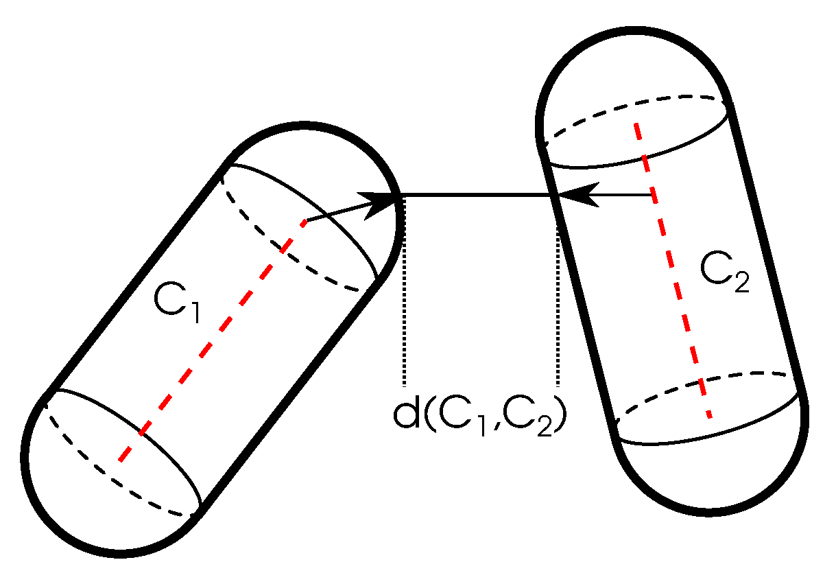
Collision avoidance also represents a key constraint that needs to be enforced in motion generation for robots. In this work, it is modeled as a set of constraints based on geometric capsules, i.e., cylinders with rounded caps [36], as shown in Figure 4. The cylinders approximate the limits of each of the links of the legs, such as the upper leg, the lower leg and the foot, for both legs. The distance between the capsules i and j is used as a constraint to avoid collision between links, i.e., , where i and j are couples of different links of the two legs.
Orientation constraints are enforced on the feet and torso of the robot only at the start and end of the phases as equality constraints, such that after touchdown, the feet are straight aligned and the torso upright with respect to the world reference frame.
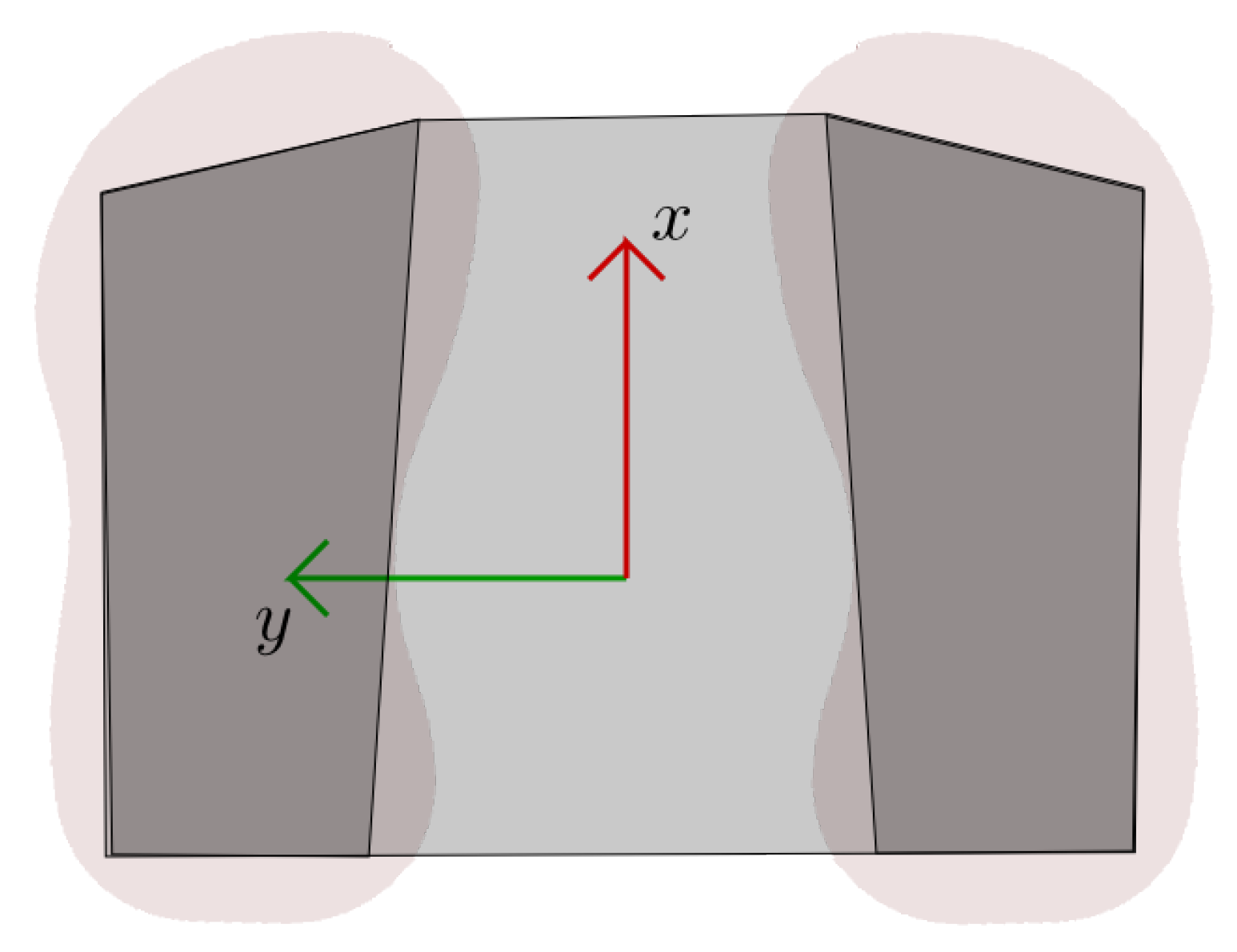
As the stability criterion, we use the ZMP, which we ensure lies inside the support polygon, which is approximated by a polygon that approximates the shape of the foot during single-support phases and an enlarged polygon including both feet and the area between the feet during double-support phases, as depicted in Figure 5. The ZMP is computed from the ground reaction forces using the whole-body model of the robot.
Periodicity constraints are enforced on the intermediate periodic step as depicted in Figure 2. We impose a one-step periodicity, i.e., at the end of the step, the state of the robot is mirrored with respect to the beginning, meaning that left and right legs have a mirrored configuration, as well as the torso, such that by mirroring the obtained periodic step, we can obtain a full sequence of multiple steps. The periodicity is imposed on states and controls .
The joint velocities are constrained to be zero at the beginning of the first phase and at the end of the last phase as equality constraints, to ensure that the motion starts from a complete stop and ends with a complete stop, i.e., .
4.3. Objective Functions
Different objective functions have been defined for the problem of walking, which can be combined by means of weighting factors:
- Minimization of joint torques squared, which is always included to ensure smooth torques (with small weighting factor):
- Minimization of absolute mechanical work:
- Minimization of joint accelerations squared in order to obtain smooth velocity trajectories (with small weighting factor):
- Torso orientation minimization (ort. min., which is sometimes also referred to as torso stabilization) in terms of torso movements with respect to the world reference:
The matrix is a weighting matrix that allows one to weight each joint differently, as not all joints have an equal contribution and an equal order of magnitude. For the time being, the same is used for all objective functions.
The reason for which the torso orientation minimization has been included as one of the objectives is that it has been observed that the torso performs large movements in order to compensate for the angular momentum, given that the robot does not have arms. Since the robot also has cameras on the torso, which faces toward the front, it is desired that the movements of the torso with respect to the world reference not be too large; this is similar to the necessity of head stabilization in many humanoid robots.
The above-listed objective functions can then be combined as one weighted objective:
The weighting factors serve to scale the contribution of each objective, but also to take into account the difference in order of magnitudes. Different combinations of the weighting factors are explored in the next section.
5. Results
In this section, we first briefly describe the software tools that have been used to achieve the results of the optimal control framework, then the numerical results are shown.
5.1. Software Tools
The multiple-phase optimal control problem is solved with the software package MUSCOD-II [37] of IWR (Interdisciplinary Center for Scientific Computing), Heidelberg University. The solution of the optimal control problem is carried out using the direct multiple-shooting method as described in [24], in which controls and states are discretized. The phase times are divided into intervals, over which a simple function (constant or linear) is chosen for the controls. State variables are parametrized with the multiple shooting method, which in this cases uses the same grid as the control discretization. From these two discretizations, we obtain a large, but structured NLP (Nonlinear Programming problem), which is solved using an adapted SQP (Sequential Quadratic Programming) method. The dynamics of the system is handled on all multiple shooting intervals in parallel with the NLP solution by means of an efficient integrator at a desired precision.
In this paper, we choose to use piecewise constant discretization for the controls, with 50 intervals for the single-support phases and 25 for the double-support phases, as they are usually shorter than the single-support phases. The number of shooting intervals is chosen the same as the control intervals.
The dynamics quantities are computed using the Rigid Body Dynamics Library (RBDL) [38], which allows for the computation of forward dynamics with contacts, as well as impact dynamics.
5.2. Numerical Results
We generated different motions with combinations of different optimality criteria. In particular, we have used the following combinations, which are summarized in Table 2:
- Minimization of joint torques, with a small weight on minimization of joint accelerations.
- Minimization of joint torques and torso orientation minimization, with a small weight on minimization of joint accelerations.
- Minimization of absolute work, with a small weight on minimization of joint torques and joint accelerations.
- Minimization of absolute work and torso orientation, with a small weight on minimization of joint torques and joint accelerations.
The computations have been carried out using MUSCOD-II and RBDL on a standard desktop PC with the i7 CPU running at 3.60 GHz with eight cores. For the whole sequence to be computed, the average time is about 12–15 h, due to the chosen high number of intervals.
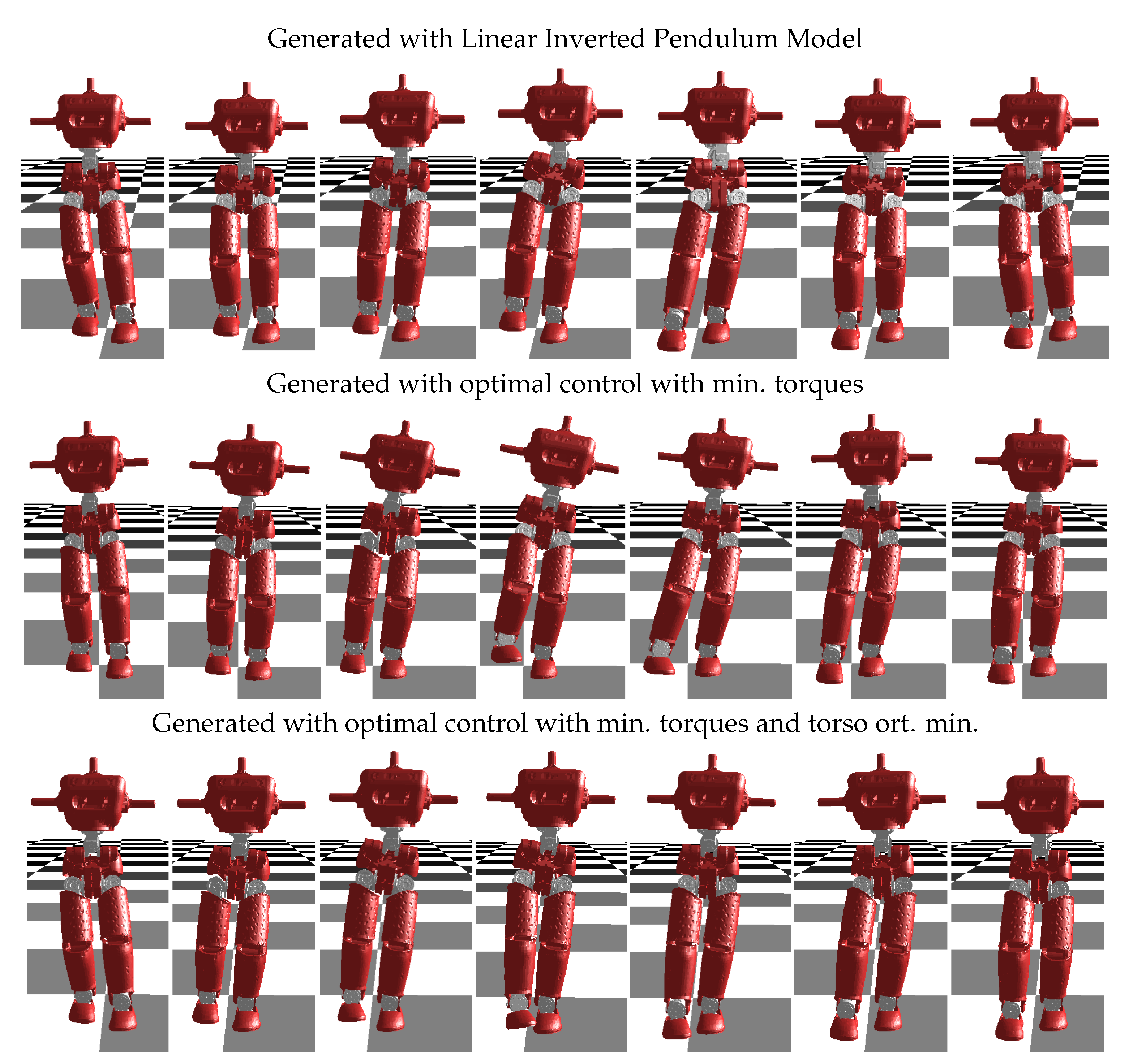
The box constraints on states and controls are set as per the hardware limits of the robot as in Table 1. The initial guess is generated from a sequence of walking motion obtained with the reduced models from our previous works and set as the same for all combinations of objectives considered, as setting the initial guesses all to zeros might lead to longer computation times in such a large and complex nonlinear optimization problem. We cannot ensure that the obtained results are completely independent of the initial guess, but the outcomes have shown that the resulting motions show differences with respect to the ones generated with reduced models. This can be seen in a more intuitive way from the example of a motion sequence of a single step shown in Figure 6. The first sequence is a motion generated with the 3D Linear Inverted Pendulum Model (LIPM), in this case, the whole-body motion was obtained applying inverse kinematics to the given center of mass (CoM) and feet trajectories from a pattern generator. In order to generate feasible trajectories, the orientations of feet and torso have been constrained with respect to the world reference frame. In contrast to the first sequence, the second sequence, which is generated with optimal control with minimization of torques (Case 1 in Table 2), shows a clear change in the orientation of both torso and swing foot. As also discussed in Section 4, the stabilization of the torso might be a desired feature; therefore, in the third sequence, it is possible to see how the torso is stabilized using the set of objectives as per Case 2 in Table 2.
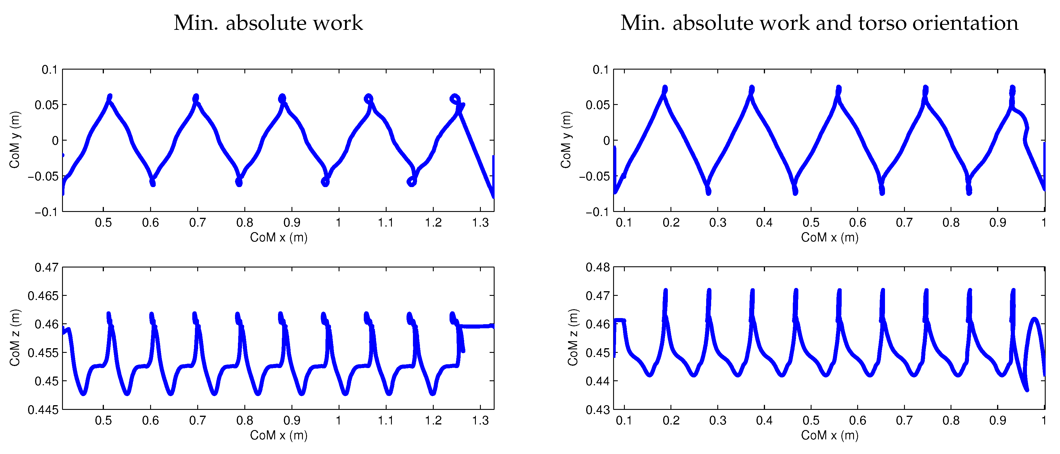
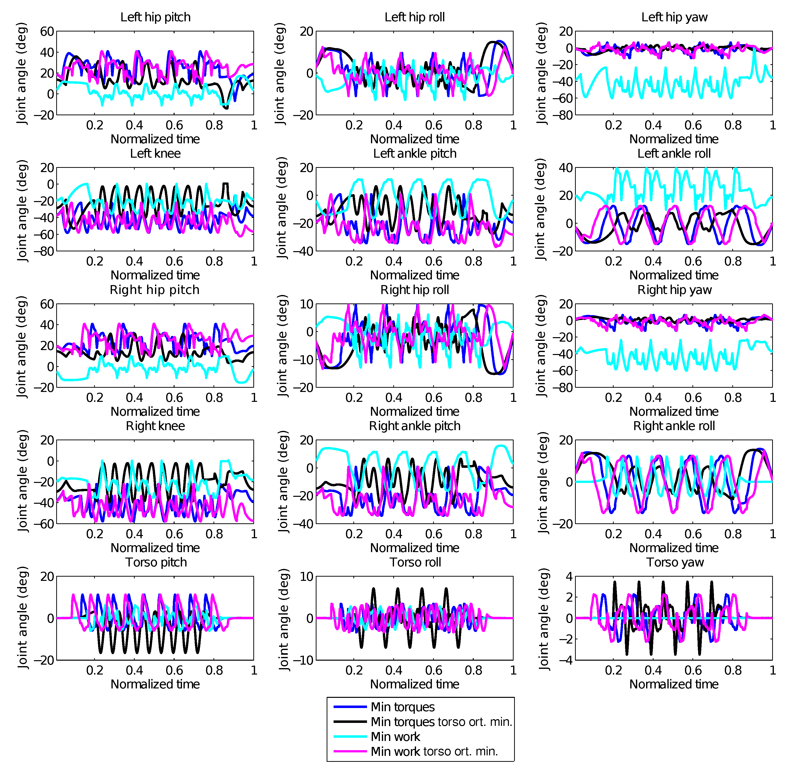
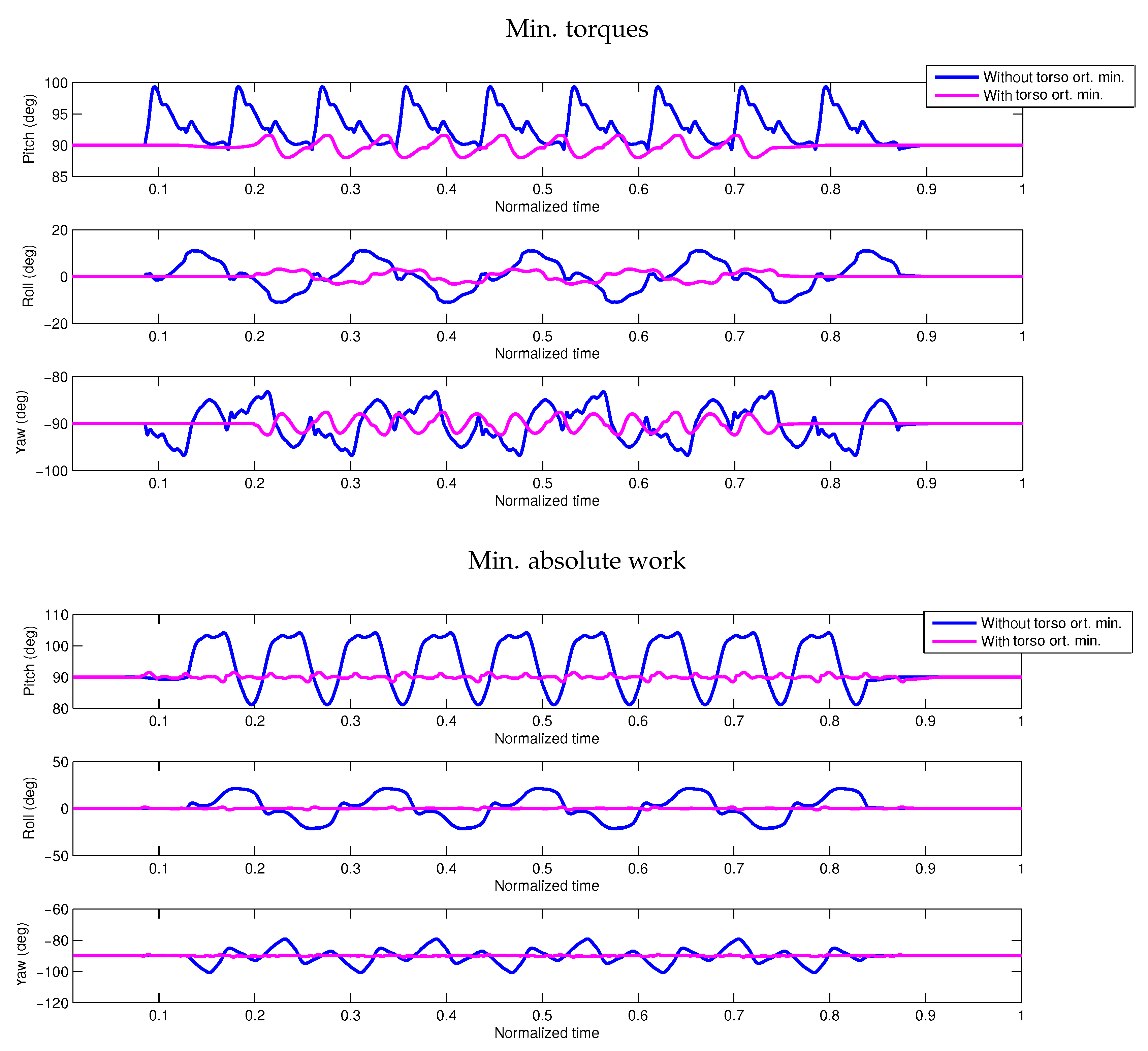
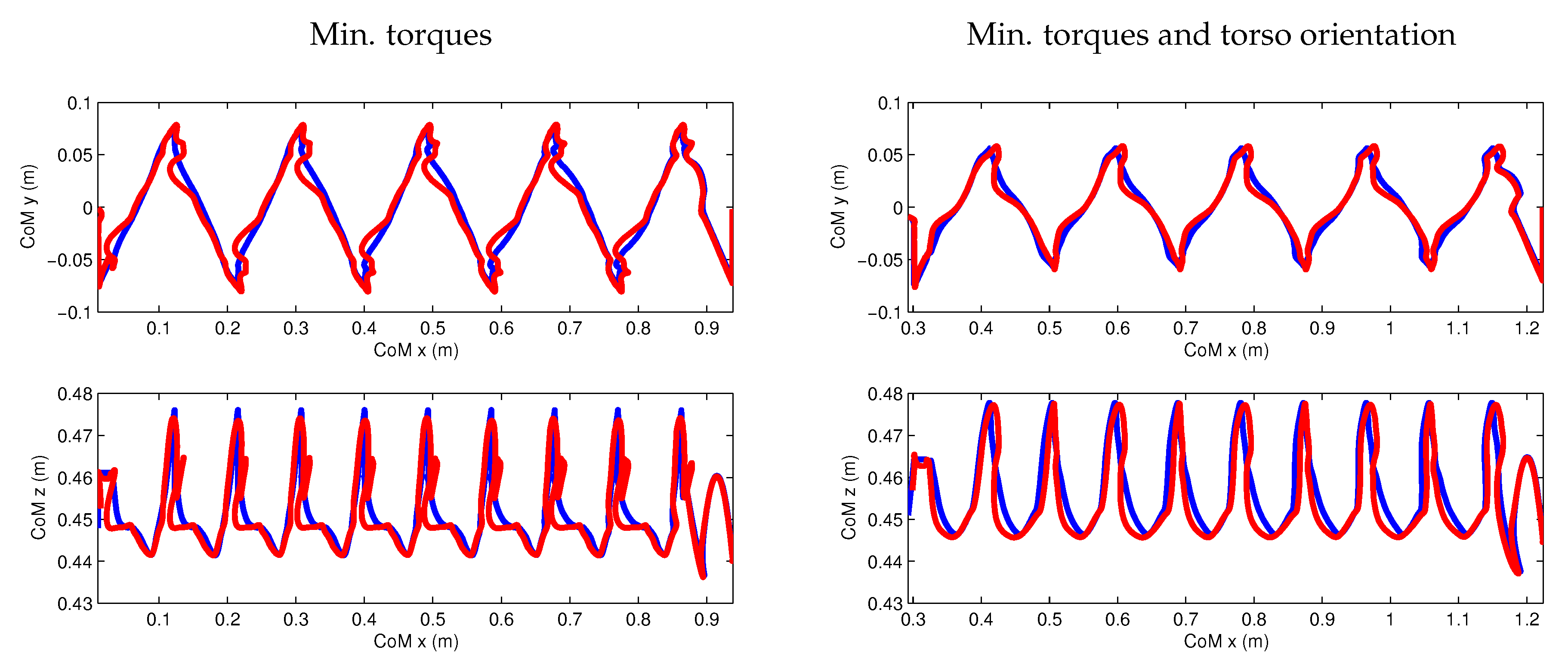
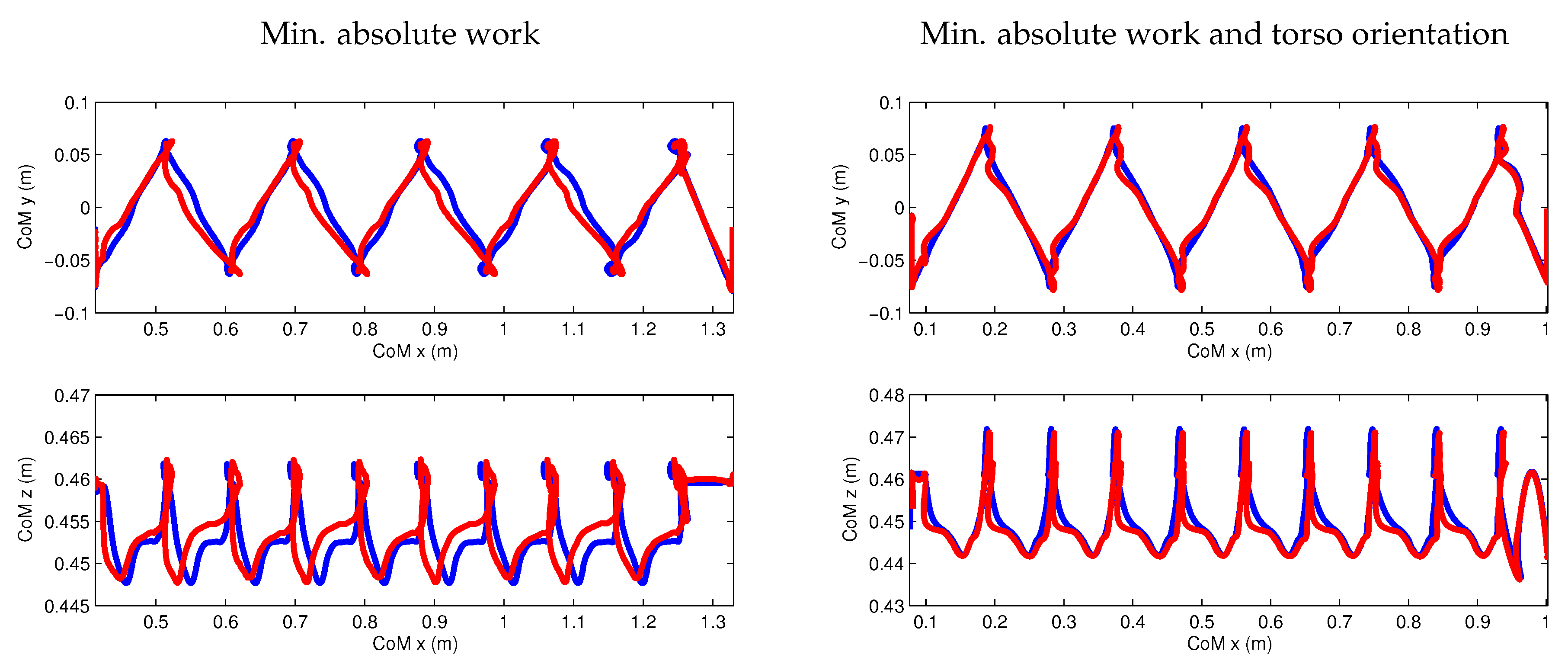
In order to show the results in a more consistent way, the intermediate periodic step has been concatenated into nine steps, resulting in a sequence of a total of 11 steps for each of the cases as listed in Table 2. The resulting CoM trajectories are shown in Figure 7, and the whole-body joint trajectories are shown in Figure 8. The effect of the torso orientation minimization can be seen in a clear way in Figure 9, which shows the orientation of the torso with respect to the world reference frame during the whole walking sequence.
From the results, with respect to methods based on reduced models, a major difference that can be observed is the variation in height of the CoM, which is usually kept fixed due to the linearization of the ZMP equations. Using optimal control instead, we have not introduced such a constraint, and as we can observe from Figure 8, the knee joint has big variations and reaches also completely stretched configurations. The CoM height variation presents however spikes when switching to the next step; these spikes are due to the impacts, which are set with zero velocity as per our assumptions in Section 3. In future work, they could be reduced by minimizing the impact forces. We can also observe that the CoM projection on the ground ( plane) is still very similar to what is usually obtained with the reduced models as in [8,23]. This is mainly due to mechanical design and restrictions of the robot itself, such as the rigid flat feet and also the missing arms. The reason for which the robot swings the torso without orientation minimization is to compensate for the angular momentum. If the robot had arms, they could be used to achieve angular momentum compensation, but this is not the case for HeiCub. As a matter of fact, we can observe from Figure 6 that when the torso orientation minimization is introduced, the robot takes steps with a smaller step width during the swing phase with respect to the case when there is no torso orientation minimization. From Figure 7 and Figure 8, we can also observe the differences between the motion obtained with minimization of torques and absolute work, where the latter shows a more constant variation in the CoM trajectory and the legs are turned inwards.
6. Experimental Validation
In order to test the obtained motion sequences on the robot, the periodic step has been concatenated to obtain a longer sequence of walking for nine periodic steps. The motions are executed on the robot by means of position control in open loop with closed loop joint angle tracking. This choice is due to the fact that torque control for walking on the iCub family of robots still cannot ensure good torque tracking, as the robot does not have joint torque sensors; the torques are estimated via force torque sensors that often incur in saturation issues at impacts and cannot therefore ensure precise torque tracking for motions such as walking.
The trajectories obtained from the optimal control framework are discretized as per the discretization grid chosen for MUSCOD-II, which does not correspond to the thread rate required by the robot controller. Due to the choice of letting the time be free in the optimization, it is not possible to choose a discretization grid that corresponds exactly to the thread rate. Furthermore, the number of shooting nodes would be too high for the problem to be solvable in a reasonable time. Therefore, all the trajectories have been interpolated with a spline interpolation in order to obtain the correct number of samples required by the robot controller. Furthermore, it is to be noted that currently on the robot, there is no proper implementation of the floating base estimation; therefore, the sliding effects that might occur during the execution of the motions are not compensated. The CoM trajectories of the robot are obtained with the computed floating based and the joint angle trajectories from the encoders.
The robot has executed all four obtained motions, proving the feasibility of the motions and of the periodicity constraints, as can be seen in the Supplementary Video S1. We can see the resulting CoM trajectories in red in Figure 10. We can observe from the results that the CoM trajectories could be followed closely by the robot; however, when the torso orientation minimization is not included, a bigger deviation can be observed in the height of the CoM trajectories in correspondence with the spikes; this is due to the impact forces as mentioned in the previous section. It seems however that the introduction of torso orientation minimization has a damping effect on the error when executed on the robot.
To compare in a more systematic way the outcomes of the optimal control framework on the robot with the results obtained in our previous works with reduced models, we computed the key performance indicators, which are illustrated in detail in the following section.
Key Performance Indicators
The Key Performance Indicators (KPIs) are a series of indicators developed in the European Project KoroiBot (http://www.koroibot.eu) designed to compare the performances of different methods applied on humanoid robots. These indicators are meant to compare the walking capabilities of the same humanoid robot with different control approaches and/or methodologies, and not to compare different robots, as it is highly difficult to compare robots that are very different in size and mechanical structure.
For the HeiCub, a subset of the KPIs has been defined in our previous works [8,23]. In the following, we give a brief explanation of the measured indicators, which were chosen based on quantities that are measurable from the robot sensors:
- Walking velocity :The maximum achieved walking velocity; in the case of motions generated with optimal control, this corresponds to the velocity of the resulting sequence.
- Walking timings and step period:Single- and double-support times of a single step, the whole duration of which is indicated as the step period. In the case of optimal control, we consider the timings of the periodic step.
- Cost of transport:The cost of transport is defined as a unitless quantity, where M is the total number of motors, and are the current and voltage measurements of the motor m, is the mass of the robot and d is the traveled distance.
- Froude number:where is the robot leg length. The Froude number is a dimensionless number used in fluid mechanics to characterize the resistance of an object moving through water. Alexander used it to characterize animal locomotion, given the that also legged locomotion is a dynamic motion in gravity [39]. A given Froude number can be assigned to a certain walking style. Running, for example, starts at a Froude number of approximately
- Precision of task execution:Expressed in terms of tracking errors. The root mean square error is computed by summing the squared difference between the measurement and the desired position over all points of the whole trajectory.
The KPIs computed for each of the combinations of objective functions as in Table 2 are reported in Table 3 for the whole sequence, while in Table 4, Table 5 and Table 6, a few KPIs referred to the three steps of the optimized sequence: starting step, periodic step and ending step. In these tables, we report also the ones obtained from previous works [8,23] for comparison purposes. As we can see from these tables, the cost of transport could be reduced with the minimization of torques, while the minimization of mechanical work does not show significant improvements in these indicators with respect to the reduced models. In particular, when minimizing work, the cost of transport is higher with respect to the LIPM model, which seems to contradict the wanted objective. It has to be noted that this might be due to the different formulations used for the objective function and the computation of the cost of transport. The cost of transport is computed with data from the robot motors, which could also have some measurement errors.
When stabilizing the torso orientation, the motion generated using optimal control outperforms the reduced model in walking speed as the double-support time is much shorter; as a matter of fact, also the cost of transport and Froude number are better in this case with respect to the other cases. A higher Froude number indicates basically faster walking both in terms of speed and covered distance; in fact, we can observe that in the case of minimizing torque and introducing torso orientation minimization, the Froude number is the highest, while in the case of minimum work only, it is quite low due to the longer step timings. Tracking errors, such as joint tracking and CoM tracking errors, appear to be overall smaller with respect the case of reduced models, with all objective function combinations. These errors are slightly bigger with the faster walking motion, i.e., the case with minimization of torques and torso orientation minimization, which are still smaller than the case of reduced models. In our objective functions, we did not aim at maximizing walking velocity, but rather left the optimization to find the best solution for the given objective; therefore, it was not expected that the walking speed would necessarily outperform the reduced models. The results however show that the robot can achieve faster walking within its physical limitations, which was not possible with the reduced models.
7. Discussion and Conclusions
In this paper, we have presented the first results of optimal control methods applied to whole-body models of an iCub robot for generating walking motions using a direct multiple shooting method. We have also described the underlying framework and model in much detail. In contrast to other approaches to motion generation, optimization is an all-at-once approach that determines all characteristics of a motion simultaneously to optimize a chosen performance criterion called the objective or cost function and to satisfy all important constraints related to the robot and the task description. For this research, we have focused on the HeiCub robot, which is a reduced version of the iCub with no head and no arms, but the same approach could be applied to the full iCub by just using the corresponding model, which is also available.
In our previous research, the HeiCub had already achieved walking, using methods based on reduced models such as the LIPM and the table cart, and these approaches also have been transferred to the full iCub. These experiences also allowed us to identify parameters and physical constraints that were now included in the optimal control problem formulations. Even though the simplified approaches allowed one to generate a variety of walking motions on level ground in different directions (forward, backward, sidewards) and up and down stairs and slopes, the motions showed some of the typical characteristics of walking based on simplified models, e.g., keeping the pelvis at (nearly) constant height, resulting in a less dynamic appearance of the gait. In addition, the weight distribution of the HeiCub robot violates some of the center of mass assumptions taken for the simple models (see Section 2), because its legs are comparatively heavy. Walking generation methods taking into account the precise mass distribution of the robot therefore seemed to be very promising to generate more suitable motions on the robot, especially since we already had positive experiences with such methods with generating squatting motions and simple push recovery steps for the same robot [40,41], as well as complex walking motions for other humanoid robots, such as HRP-2 [15].
The results of this first optimization study are very encouraging. We have shown that
- It is possible to formulate optimal control problems for the iCub/HeiCub robots that allow one to simultaneously generate periodic walking motions, as well as the necessary starting and stopping steps that take the robot from standing position to the periodic cycle, as well as from back to standing position. So far, only single starting and stopping steps have been included in the formulation, but it is straightforward to extend this to multiple steps, which may be required for faster walking.
- Different objective functions result in visibly different walking styles for the robot. In particular we have compared a minimization of torques squared and of absolute mechanical work, in both cases with and without a combined term on torso stabilization. A very small term on joint accelerations was present in all objective functions. Further objective functions are the subject of current research. The fact that we are able to generate walking in different styles in an automated way already presents a significant difference from the classical walking generation methods using the simple models for which all outcomes look very similar.
- The resulting motions are still not close to biological motion, but they have made significant progress in the right direction. In particular, the motions show variations in the height of the CoM. See the discussion below for making optimized walking motions more biological or “human-like”.
As discussed in the Introduction, optimization can be a very helpful tool to bring humanoid robots to their technical limits, i.e., to make the most out of given robot hardware. This requires that suitable optimization criteria targeting an improvement of performance be used, which has not been done so far in this study. In current research, we are also looking at step length, step frequency and walking speed maximization. The objective functions used in this study targeted the smoothness of motions, as well as measures of efficiency. We are also interested in using human-inspired criteria for generating humanoid motions. For this, we can rely on the results of inverse optimal control studies, which identify criteria underlying human motions from motion capture data. These criteria can then be applied to humanoid models in optimal control problem formulations as the one presented in this paper. We have demonstrated a similar approach based on simpler template models of human and humanoid walking in [19], also for the HeiCub, but it would be new to apply this concept of transferring bio-inspired optimization criteria to whole-body models of the HeiCub robot.
There are several characteristics of the robot and its inherent control approaches that limit the performance. The fact that the robot has no arms and all counteraction to the lower limb angular momentum has to be done by the torso already prevents it from acting in a fully-human-like manner. While humans exhibit a strongly stabilized head and torso while walking forward on flat ground, such a criterion induces strong limitations to the motion if no actions of the arms are possible. In this context, also the extension of the work to the full iCub model would be interesting to see how the arms are used for angular momentum compensation.
As discussed before, the HeiCub and iCub robots also have several limitations in the joint angles, the angular velocities and the joint torques that prevent them from coming close to human performance. In addition, the current foot shape and controllers impose that the robot, as most contemporary robots, walks with flat feet and cannot, e.g., have heel only or toe only contact as humans can, resulting in limited step lengths and step heights (the latter on stairs). The optimal control approach presented in this paper could also serve to generate walking motions with partial or more flexible foot contact, as soon as the hardware allows it. While optimization can help to exploit the capabilities of the robot hardware, it is best to simultaneously also improve the hardware to have an overall performance improvement.
As mentioned in Section 2, the robot is equipped with series elastic actuators. The model of the robot with a reduced number of DOF, but including elasticity has been used in optimal control frameworks for the generation of squat and push recovery motions [40,41]; the current framework for walking will be extended to include also the elasticity of the elastic actuators, which will be mounted for the experimental validations. The optimal control problem including elasticity is a larger nonlinear problem with respect to the one described in this work, which will require longer computation times. On the hardware side, a proper control for the SEA needs to be implemented.
In addition to the extensions already discussed, future work on whole-body optimal control of the HeiCub robot will also include more complex walking scenarios like stairs and slopes for which the approach based on simple models is even further from the real behavior than for motion on flat ground and for which many details of the motion such as the foot trajectories in the air had to be inserted manually. We expect that for these motions, the gain in performance and walking quality by the whole-body optimal control approach will be more significant than for walking.
The computation times for the method presented here are very long for multiple reasons. First, it should be noted that the whole-body dynamic equations for a complex multi-phase system have to be solved (and derivatives have to be computed) precisely in every optimization step. Second, the discretization chosen for the controls and the multiple shooting intervals in the present study is very accurate, and from the optimal control perspective, a much coarser grid would be possible without any problem. This was done in the attempt to get closer to the robots’ control intervals, but could also be solved by means of interpolation in the interest of higher efficiency. However what is most important is that solving such optimal control problems online each time the robot has to perform a motion can be avoided. In previous research, we developed an approach based on a combination of optimal control with movement primitives [18]. In this method, optimal control serves to generate multiple training data in an offline process on the basis of which movement primitives are learned. This takes some time, but is not time-critical and only has to be done once for a class of motions. New versatile motions can then be efficiently generated online, just using the movement primitives without the need to solve any optimal control problems. As has been demonstrated in the case of another robot, the resulting motions are close to optimal and dynamic feasibility and work well on the real system. We therefore expect this to be a very interesting approach for the iCub/HeiCub robot, which makes this a very important argument to further explore whole-body optimal control in the context of bio-inspired walking generation for these robots.
Supplementary Materials
The following are available online at https://www.mdpi.com/2076-3417/8/2/278/s1, Video S1: Experimental Results.
Acknowledgments
The work carried out in this paper was funded by the Heidelberg Graduate School of Mathematical and Computational Methods for the Sciences (HGS MathComp), founded by DFG Grant GSC 220 in the German Universities Excellence Initiative. We acknowledge financial support by Deutsche Forschungsgemeinschaft within the funding programme Open Access Publishing, by the Baden-Württemberg Ministry of Science, Research and the Arts and by Ruprecht-Karls-Universität Heidelberg. This work is based on work that was carried out for the European Project KoroiBot concluded in September 2016, which received funding from the European Union Seventh Framework Programme (FP7/2013) under Grant Agreement No. 611909. We wish to thank the Simulation and Optimization group of H. G. Bock at the Heidelberg University for providing the optimal control code MUSCOD.
Author Contributions
Yue Hu and Katja Mombaur jointly planned and designed the study and contributed to analyzing the results and writing the paper. Yue Hu has carried out the computations and the experiments.
Conflicts of Interest
The authors declare no conflict of interest. The funding sponsors had no role in the design of the study; in the collection, analyses or interpretation of data; in the writing of the manuscript; nor in the decision to publish the results.
References
- Vukobratović, M.; Borovac, B. Zero-moment point—Thirty five years of its life. Int. J. Humanoid Robot. 2004, 1, 157–173. [Google Scholar] [CrossRef]
- Mukovskiy, A.; Vassallo, C.; Naveau, M.; Stasse, O.; Soueres, P.; Giese, M.A. Adaptive synthesis of dynamically feasible full-body movements for the humanoid robot HRP-2 by flexible combination of learned dynamic movement primitives. Robot. Auton. Syst. 2017, 91, 270–283. [Google Scholar] [CrossRef]
- Ishiguro, Y.; Kojima, K.; Sugai, F.; Nozawa, S.; Kakiuchi, Y.; Okada, K.; Inaba, M. Bipedal Oriented Whole Body Master-Slave System for Dynamic Secured Locomotion with LIP Safety Constraints. In Proceedings of the IEEE International Conference on Intelligent Robots and Systems (IROS), Vancouver, BC, Canada, 24–28 September 2017; pp. 376–382. [Google Scholar]
- Kajita, S.; Kanehiro, F.; Kaneko, K.; Fujiwara, K.; Yokoi, K.; Hirukawa, H. A Realtime Pattern Generator for Biped Walking. In Proceedings of the IEEE International Conference on Robotics and Automation (ICRA), Washington, DC, USA, 1–15 May 2002; pp. 31–37. [Google Scholar]
- Kajita, S.; Kanehiro, F.; Kaneko, K.; Fujiwara, K.; Harada, K.; Yokoi, K.; Hirukawa, H. Biped walking pattern generation by using preview control of zero-moment point. In Proceedings of the IEEE International Conference on Robotics and Automation (ICRA), Taipei, Taiwan, 14–19 September 2003; Volume 2, pp. 1620–1626. [Google Scholar]
- Naveau, M.; Kudruss, M.; Stasse, O.; Kirches, C.; Mombaur, K.; Souères, P. A reactive walking pattern generator based on nonlinear model predictive control. IEEE Robot. Autom. Lett. 2017, 2, 10–17. [Google Scholar] [CrossRef]
- Li, Z.; Tsagarakis, N.G.; Caldwell, D.G. Walking trajectory generation for humanoid robots with compliant joints: Experimentation with COMAN humanoid. In Proceedings of the IEEE International Conference on Robotics and Automation (ICRA), Saint Paul, MN, USA, 14–18 May 2012; pp. 836–841. [Google Scholar]
- Hu, Y.; Eljaik, J.; Stein, K.; Nori, F.; Mombaur, K. Walking of the iCub humanoid robot: Implementation and performance analysis. In Proceedings of the IEEE-RAS International Conference on Humanoid Robots (Humanoids), Cancun, Mexico, 15–17 November 2016; pp. 690–696. [Google Scholar]
- Mombaur, K.; Clever, D. Inverse optimal control as a tool to understand human movement. In Geometric and Numerical Foundations of Movements; Laumond, J.P., Mansard, N., Lasserre, J.B., Eds.; Springer STAR Series: Berlin/Heidelberg, Germany, 2017. [Google Scholar]
- Ames, A.D. Human-inspired control of bipedal walking robots. IEEE Trans. Autom. Control 2014, 59, 1115–1130. [Google Scholar] [CrossRef]
- Mombaur, K. Humanoid Motion Optimization. In Humanoid Robotics—A Reference; Goswami, A., Vadakkepat, P., Eds.; Springer: Berlin/Heidelberg, Germany, 2017. [Google Scholar]
- Lengagne, S.; Vaillant, J.; Yoshida, E.; Kheddar, A. Generation of whole-body optimal dynamic multi-contact motions. Int. J. Robot. Res. 2013, 32, 1104–1119. [Google Scholar] [CrossRef]
- Miossec, S.; Yokoi, K.; Kheddar, A. Development of a software for motion optimization of robots— Application to the kick motion of the HRP-2 robot. In Proceedings of the IEEE International Conference on Robotics and Automation (ICRA), Kunming, China, 17–20 December 2006; pp. 299–304. [Google Scholar]
- Suleiman, W.; Yoshida, E.; Laumond, J.P.; Monin, A. On humanoid motion optimization. In Proceedings of the IEEE-RAS International Conference on Humanoid Robots (Humanoids), Pittsburgh, PA, USA, 29 November–1 December 2007; pp. 180–187. [Google Scholar]
- Koch, K.H.; Mombaur, K.; Souères, P. Optimization-based walking generation for humanoids. In IFAC-SYROCO 2012; Elsevier: Amsterdam, The Netherlands, 2012; Volume 45, pp. 498–504. [Google Scholar]
- Koch, K.H.; Mombaur, K.; Souères, P. Studying the Effect of Different Optimization Criteria on Humanoid Walking Motions. In Simulation, Modeling, and Programming for Autonomous Robots; Noda, I., Ando, N., Brugali, D., Kuffner, J.J., Eds.; Springer: Berlin/Heidelberg, Germany, 2012; Volume 7628, pp. 221–236. [Google Scholar]
- Koch, K.H.; Mombaur, K.; Souères, P.; Stasse, O. Optimization based exploitation of the ankle elasticity of HRP-2 for overstepping large obstacles. In Proceedings of the IEEE/RAS International Conference on Humanoid Robots (Humanoids 2014), Madrid, Spain, 18–20 November 2014; pp. 733–740. [Google Scholar]
- Clever, D.; Harant, M.; Mombaur, K.; Naveau, M.; Stasse, O.; Endres, D. Cocomopl: A novel approach for humanoid walking generation combining optimal control, movement primitives and learning and its transfer to the real robot HRP-2. IEEE Robot. Autom. Lett. 2017, 2, 977–984. [Google Scholar] [CrossRef]
- Clever, D.; Mombaur, K.D. An Inverse Optimal Control Approach for the Transfer of Human Walking Motions in Constrained Environment to Humanoid Robots. In Proceedings of the Robotics: Science and Systems, Ann Arbor, MI, USA, 18–22 June 2016. [Google Scholar]
- Posa, M.; Kuindersma, S.; Tedrake, R. Optimization and stabilization of trajectories for constrained dynamical systems. In Proceedings of the 2016 IEEE International Conference on Robotics and Automation (ICRA), Stockholm, Sweden, 16–21 May 2016; pp. 1366–1373. [Google Scholar]
- Hereid, A.; Cousineau, E.A.; Hubicki, C.M.; Ames, A.D. 3D dynamic walking with underactuated humanoid robots: A direct collocation framework for optimizing hybrid zero dynamics. In Proceedings of the 2016 IEEE International Conference on Robotics and Automation (ICRA), Stockholm, Sweden, 16–21 May 2016; pp. 1447–1454. [Google Scholar]
- Metta, G.; Natale, L.; Nori, F.; Sandini, G.; Vernon, D.; Fadiga, L.; Von Hofsten, C.; Rosander, K.; Lopes, M.; Santos-Victor, J.; et al. The iCub humanoid robot: An open-systems platform for research in cognitive development. Neural Netw. 2010, 23, 1125–1134. [Google Scholar] [CrossRef] [PubMed]
- Stein, K.; Hu, Y.; Kudruss, M.; Naveau, M.; Mombaur, K. Closed loop control of walking motions with adaptive choice of directions for the iCub humanoid robot. In Proceedings of the IEEE International Conference on Humanoid Robots (Humanoids), Birmingham, UK, 15–17 November 2017. [Google Scholar]
- Bock, H.; Plitt, K. A Multiple Shooting Algorithm for Direct Solution of Optimal Control Problems; Pergamon Press: Oxford, UK, 1984; pp. 243–247. [Google Scholar]
- Mombaur, K.; Longman, R.; Bock, H.; Schlöder, J. Open-loop stable running. Robotica 2005, 23. [Google Scholar] [CrossRef]
- Tikhanoff, V.; Pattacini, U.; Natale, L.; Metta, G. Exploring affordances and tool use on the iCub. In Proceedings of the IEEE-RAS International Conference on Humanoid Robots (Humanoids), Atlanta, GA, USA, 15–17 October 2013; pp. 130–137. [Google Scholar]
- Mar, T.; Tikhanoff, V.; Metta, G.; Natale, L. Self-supervised learning of grasp dependent tool affordances on the iCub Humanoid robot. In Proceedings of the IEEE International Conference on Robotics and Automation (ICRA), Seattle, WA, USA, 26–30 May 2015; pp. 3200–3206. [Google Scholar]
- Nori, F.; Traversaro, S.; Eljaik, J.; Romano, F.; Del Prete, A.; Pucci, D. iCub whole-body control through force regulation on rigid non-coplanar contacts. Front. Robot. AI 2015, 2, 6. [Google Scholar] [CrossRef]
- Parmiggiani, A.; Metta, G.; Tsagarakis, N. The mechatronic design of the new legs of the iCub robot. In Proceedings of the IEEE-RAS International Conference on Humanoid Robots (Humanoids), Osaka, Japan, 29 November–1 December 2012; pp. 481–486. [Google Scholar]
- Colasanto, L.; Tsagarakis, N.; Caldwell, D. A Compact Model for the Compliant Humanoid Robot COMAN. In Proceedings of the IEEE International Conference on Biomedical Robotics and Biomechatronics, Rome, Italy, 24–27 June 2012; pp. 688–694. [Google Scholar]
- Dallali, H.; Kormushev, P.; Li, Z.; Caldwell, D. On Global Optimization of Walking Gaits for the Compliant Humanoid Robot, COMAN Using Reinforcement Learning. Cybern. Inf. Technol. 2012, 12, 39–52. [Google Scholar] [CrossRef]
- Moro, F.L.; Tsagarakis, N.G.; Caldwell, D.G. Walking in the resonance with COMAN robot with trajectories based on human kinematic motion primitives (kMPs). Auton. Robot. 2014, 36, 331–347. [Google Scholar] [CrossRef]
- Tsagarakis, N.G.; Laffranchi, M.; Vanderborght, B.; Caldwell, D.G. A Compact Soft Actuator Unit for Small Scale Human Friendly Robots. In Proceedings of the International Conference on Robotics and Automation (ICRA), Kobe, Japan, 2–17 May 2009; pp. 4356–4362. [Google Scholar]
- Felis, M.; Mombaur, K.D.; Berthoz, A. An Optimal Control Approach to Reconstruct Human Gait Dynamics from Kinematic Data. In Proceedings of the IEEE-RAS 15th International Conference on Humanoid Robots (Humanoids), Seoul, Korea, 3–5 November 2015. [Google Scholar]
- Hu, Y.; Mombaur, K. Analysis of human leg joints compliance in different walking scenarios with an optimal control approach. In Proceedings of the 6th IFAC International Workshop on Periodic Control Systems (PSYCO 2016), Eindhoven, The Netherlands, 29 June–1 July 2016; Volume 49, pp. 99–106. [Google Scholar]
- Ketchel, J.; Larochelle, P. Collision detection of cylindrical rigid bodies for motion planning. In Proceedings of the IEEE International Conference on Robotics and Automation (ICRA), Orlando, FL, USA, 15–19 May 2006; pp. 1530–1535. [Google Scholar]
- Leinweber, D.; Bauer, I.; Bock, H.; Schloeder, J. An efficient multiple shooting based reduced SQP strategy for large-scale dynamic process optimization. Part I: Theoretical aspects. Comput. Chem. Eng. 2003, 27, 157–166. [Google Scholar] [CrossRef]
- Felis, M.L. RBDL: An efficient rigid-body dynamics library using recursive algorithms. Auton. Robot. 2017, 41, 495–511. [Google Scholar] [CrossRef]
- Alexander, R.M. Principles of Animal Locomotion; Princeton University Press: Princeton, NJ, USA, 2003. [Google Scholar]
- Hu, Y.; Nori, F.; Mombaur, K. Squat Motion Generation for the Humanoid Robot iCub with Series Elastic Actuators. In Proceedings of the IEEE RAS & EMBS International Conference on Biomedical Robotics and Biomechatronics (BioRob), Singapore, 26–29 June 2016; pp. 207–212. [Google Scholar]
- Hu, Y.; Mombaur, K. Optimal Control Based Push recovery Strategy for the humanoid robot iCub with Series Elastic Actuators. In Proceedings of the IEEE/RSJ International Conference on Intelligent Robots and Systems (IROS), Vancouver, BC, Canada, 24–28 September 2017; pp. 5842–5852. [Google Scholar]
Figure 1.
The HeiCub (iCub of Heidelberg University) humanoid robot. In red, the series elastic actuators, which are not considered in the context of this work.
Figure 1.
The HeiCub (iCub of Heidelberg University) humanoid robot. In red, the series elastic actuators, which are not considered in the context of this work.

Figure 2.
Walking phases of HeiCub. DS = Double Support, LSS = Left Single Support, RSS = Right Single Support, LTD = Left Touch Down, RTD = Right Touch Down. The whole sequence can be seen as three sub-sequences. The periodic step can be repeated for a desired number of times that do not need to be further modeled.

Figure 3.
Feet shapes of the HeiCub robot. Three points are defined for contact modeling on each foot.
Figure 3.
Feet shapes of the HeiCub robot. Three points are defined for contact modeling on each foot.

Figure 4.
Collision avoidance with rounded caps. The distance between the two is calculated as d.

Figure 5.
Approximation of the support area of the foot. The darker grey zones delimit the support areas for single support cases. The lighter grey zone changes according to the positions of the feet.
Figure 5.
Approximation of the support area of the foot. The darker grey zones delimit the support areas for single support cases. The lighter grey zone changes according to the positions of the feet.

Figure 6.
Example sequences of one step motions from using the reduced model, the whole-body model minimizing torques and the whole-body model with torso orientation minimization.
Figure 6.
Example sequences of one step motions from using the reduced model, the whole-body model minimizing torques and the whole-body model with torso orientation minimization.

Figure 7.
Center of mass trajectories of a full sequence with nine periodic steps combinations of objectives as in Table 2.
Figure 7.
Center of mass trajectories of a full sequence with nine periodic steps combinations of objectives as in Table 2.


Figure 8.
Joint angle trajectories of all the 15 DOF of the robot, obtained for the four combinations of objective functions. Time is normalized for all trajectories for comparison purposes. It is to be noted that torso orientation minimization does not mean reduction of the movements of the torso joints, but the orientation w.r.t. the world reference.

Figure 9.
Torso orientation trajectories for the two cases of minimization of torques and absolute work. The orientation is expressed with respect to the world reference frame. The nominal reference (torso upright) is [90, 0, −90]. Time is normalized for all trajectories for comparison purposes.
Figure 9.
Torso orientation trajectories for the two cases of minimization of torques and absolute work. The orientation is expressed with respect to the world reference frame. The nominal reference (torso upright) is [90, 0, −90]. Time is normalized for all trajectories for comparison purposes.

Figure 10.
[Hardware experiment result.] Center of mass trajectories obtained on the robot (in red) with all four combinations of objective functions as in Table 2.
Figure 10.
[Hardware experiment result.] Center of mass trajectories obtained on the robot (in red) with all four combinations of objective functions as in Table 2.


Table 1.
HeiCub joint limits.
| Joint | Range Limits (deg) | Velocity Limits (deg/s) | Torque Limits (Nm/s) |
|---|---|---|---|
| l_hip_pitch, r_hip_pitch | [−33, 100] | [−100, 100] | [−50, 50] |
| l_hip_roll, r_hip_roll | [−19, 90] | [−150, 150] | [−50, 50] |
| l_hip_yaw, r_hip_yaw | [−75, 75] | [−150, 150] | [−50, 50] |
| l_knee, r_knee | [−100, 0] | [−150, 150] | [−50, 50] |
| l_ankle_pitch, r_ankle_pitch | [−36, 27] | [−150, 150] | [−50, 50] |
| l_ankle_roll, r_ankle_roll | [−24, 24] | [−150, 150] | [−50, 50] |
| torso_pitch | [−20, 60] | [−150, 150] | [−50, 50] |
| torso_roll | [−26, 26] | [−150, 150] | [−50, 50] |
| torso_yaw | [−50, 50] | [−150, 150] | [−50, 50] |
Table 2.
Combination of objective functions. Minimization of torques and joint accelerations is always included with small weighting factors to ensure smooth trajectories.
Table 2.
Combination of objective functions. Minimization of torques and joint accelerations is always included with small weighting factors to ensure smooth trajectories.
| Objectives | ||||
|---|---|---|---|---|
| 1 | 1 | 0 | 0 | |
| 2 | 1 | 0 | 10 | |
| 3 | 1 | 0 | ||
| 4 | 1 | 10 |
Table 3.
[Hardware experiment result.] Key Performance Indicators (KPIs) measured for all 4 combinations of objective functions, in comparison with results with reduced models. The support times and step period refer to the ones of the periodic step. NMPC, Nonlinear Model Predictive Control.
Table 3.
[Hardware experiment result.] Key Performance Indicators (KPIs) measured for all 4 combinations of objective functions, in comparison with results with reduced models. The support times and step period refer to the ones of the periodic step. NMPC, Nonlinear Model Predictive Control.
| KPIs | Cart-Table | NMPC (LIPM) | Min Torques | Min Torques and Torso ort. | Min Work | Min Work and Torso ort. |
|---|---|---|---|---|---|---|
| (m/s) | 0.037 | 0.065 | 0.053 | 0.079 | 0.043 | 0.053 |
| (s) | 1.5/1.0 | 0.6/0.6 | 1.06/0.98 | 0.7/0.37 | 1.06/1 | 0.8/0.8 |
| step period (s) | 2.5 | 1.2 | 2.04 | 1.07 | 2.06 | 1.6 |
| Cost of Transport | 4.27 | 2.99 | 2.69 | 1.97 | 3.32 | 3.09 |
| Froude Number | 0.017 | 0.029 | 0.024 | 0.035 | 0.019 | 0.024 |
| Joint error (deg) | 1.45 | 1.21 | 1.27 | 1.29 | 1.11 | 0.9 |
| CoM error (cm) | 0.61 | 0.44 | 0.29 | 0.31 | 0.39 | 0.29 |
Table 4.
[Hardware experiment result.] Key Performance Indicators (KPIs) for the starting step.
| KPIs | Cart-Table | NMPC (LIPM) | Min Torques | Min Torques and Torso ort. | Min Work | Min Work and Torso ort. |
|---|---|---|---|---|---|---|
| Cost of Transport | 3.99 | 2.54 | 2.49 | 2.30 | 2.56 | 2.67 |
| Joint error (deg) | 1.35 | 1.12 | 1.19 | 1.22 | 1.08 | 0.9 |
| CoM error (cm) | 0.59 | 0.42 | 0.25 | 0.28 | 0.36 | 0.27 |
Table 5.
[Hardware experiment result.] Key Performance Indicators (KPIs) for the periodic step. Note that in the case of motions obtained with the cart-table and NMPC, no explicit periodicity constraints were introduced, so the data are approximated on an intermediate step that would correspond to a periodic step.
| KPIs | Cart-Table | NMPC (LIPM) | Min Torques | Min Torques and Torso ort. | Min Work | Min Work and Torso ort. |
|---|---|---|---|---|---|---|
| Cost of Transport | 4.33 | 3.10 | 2.89 | 1.90 | 3.31 | 3.19 |
| Joint error (deg) | 1.65 | 1.20 | 1.37 | 1.39 | 1.20 | 1.0 |
| CoM error (cm) | 0.63 | 0.46 | 0.31 | 0.35 | 0.40 | 0.32 |
Table 6.
[Hardware experiment result.] Key Performance Indicators (KPIs) for the ending step.
| KPIs | Cart-Table | NMPC (LIPM) | Min Torques | Min Torques & Torso ort. | Min Work | Min Work & Torso ort. |
|---|---|---|---|---|---|---|
| Cost of Transport | 4.05 | 2.64 | 2.54 | 2.20 | 2.61 | 2.62 |
| Joint error (deg) | 1.35 | 1.15 | 1.20 | 1.20 | 1.08 | 0.85 |
| CoM error (cm) | 0.61 | 0.43 | 0.26 | 0.30 | 0.38 | 0.27 |
© 2018 by the authors. Licensee MDPI, Basel, Switzerland. This article is an open access article distributed under the terms and conditions of the Creative Commons Attribution (CC BY) license (http://creativecommons.org/licenses/by/4.0/).
Share and Cite
MDPI and ACS Style
Hu, Y.; Mombaur, K. Bio-Inspired Optimal Control Framework to Generate Walking Motions for the Humanoid Robot iCub Using Whole Body Models. Appl. Sci. 2018, 8, 278. https://doi.org/10.3390/app8020278
AMA Style
Hu Y, Mombaur K. Bio-Inspired Optimal Control Framework to Generate Walking Motions for the Humanoid Robot iCub Using Whole Body Models. Applied Sciences. 2018; 8(2):278. https://doi.org/10.3390/app8020278
Chicago/Turabian StyleHu, Yue, and Katja Mombaur. 2018. "Bio-Inspired Optimal Control Framework to Generate Walking Motions for the Humanoid Robot iCub Using Whole Body Models" Applied Sciences 8, no. 2: 278. https://doi.org/10.3390/app8020278
Note that from the first issue of 2016, this journal uses article numbers instead of page numbers. See further details here.