Experiment and Simulation Investigation on the Characteristics of Diesel Spray Impingement Based on Droplet Impact Phenomenon

Abstract
:1. Introduction
2. Experiment
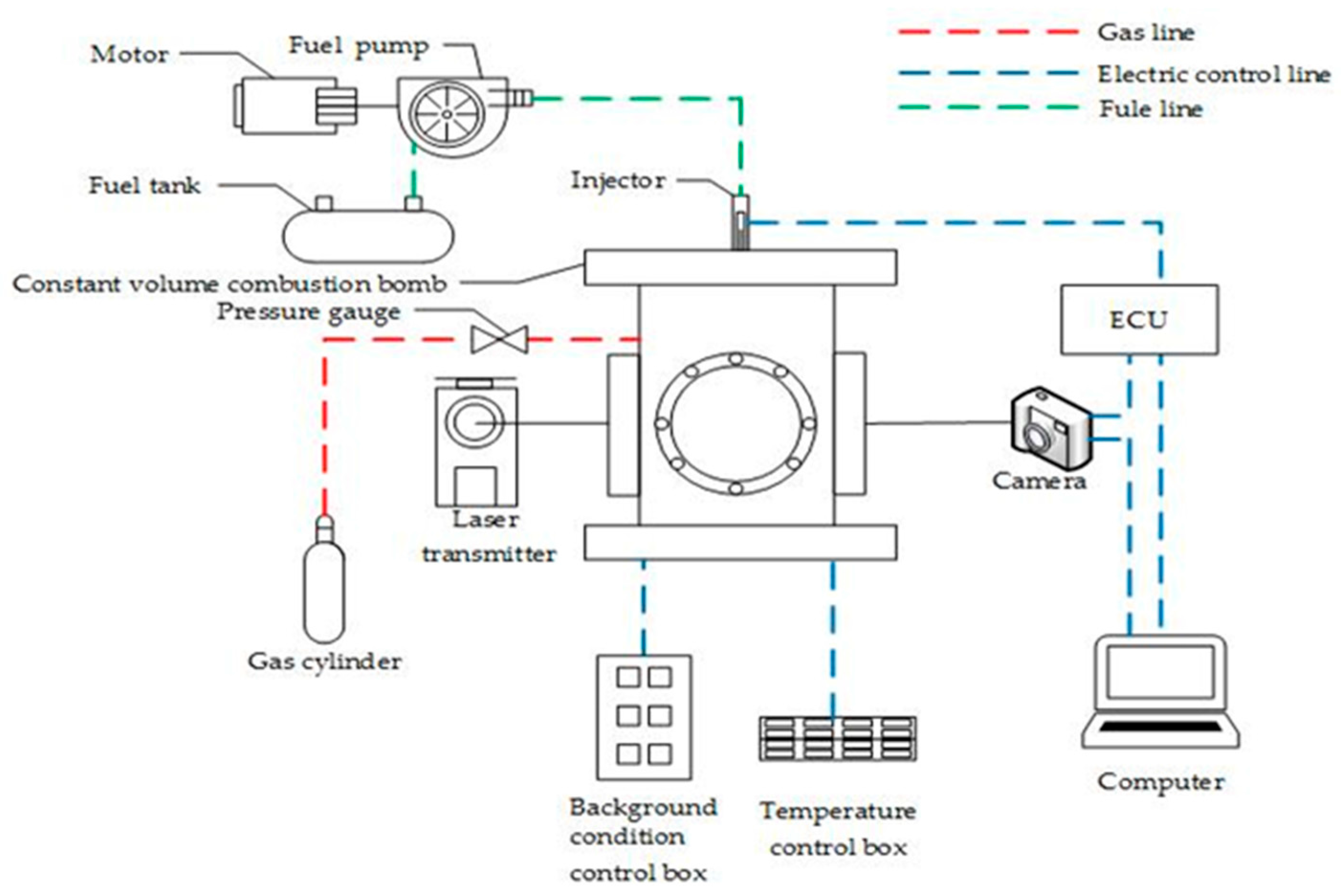
2.1. Experimental Apparatus and Procedures
2.2. Experimental Conditions
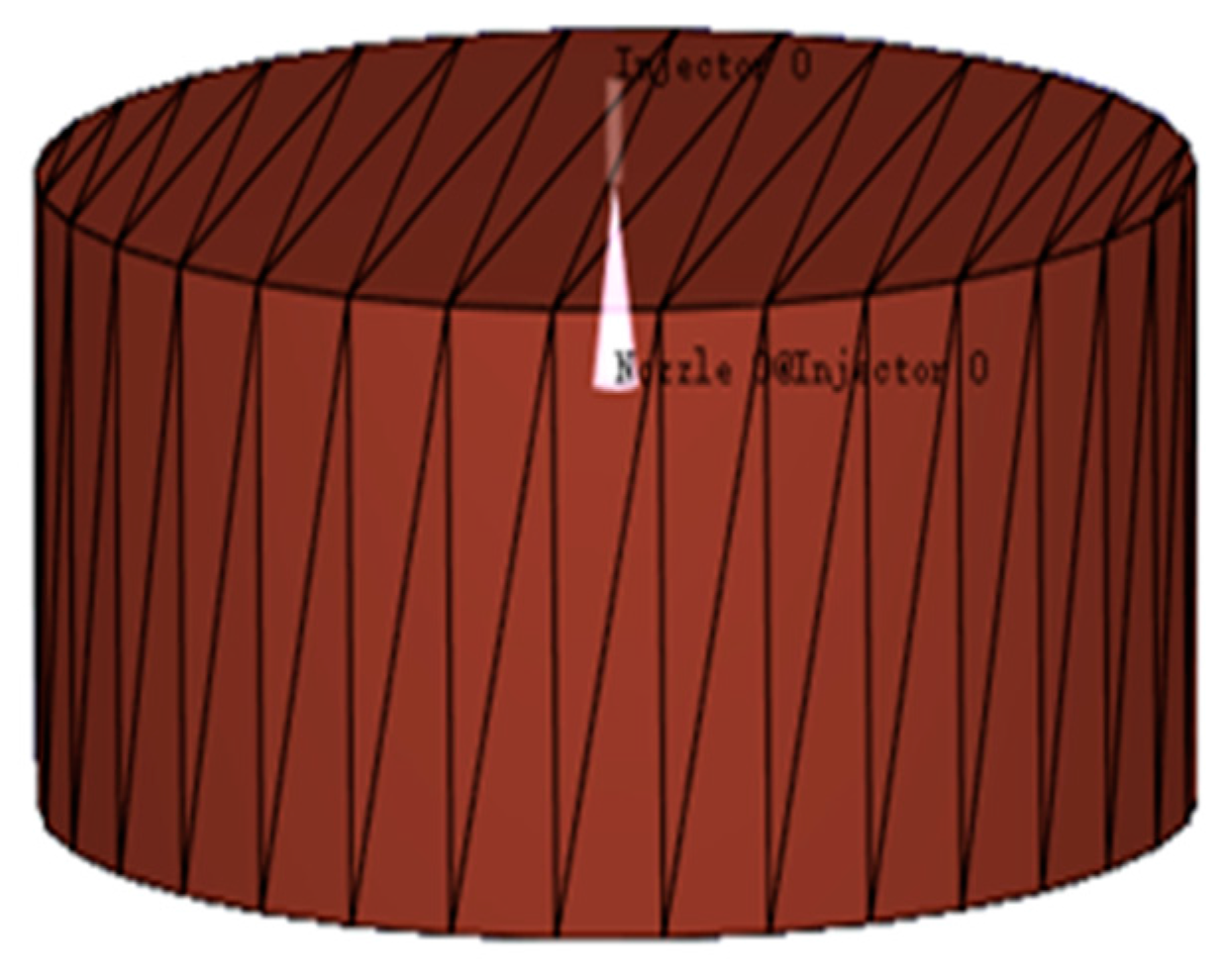
3. Simulation
3.1. Spray-Wall Impingement Parameter Definitions
3.2. Spray-Wall Characteristics of the Empirical Calculation
3.3. Impingement oil Film Spread Modes
3.4. Calculation
4. Results and Discussion
4.1. Spray Process
4.2. Spray Height
4.3. Spray Radius
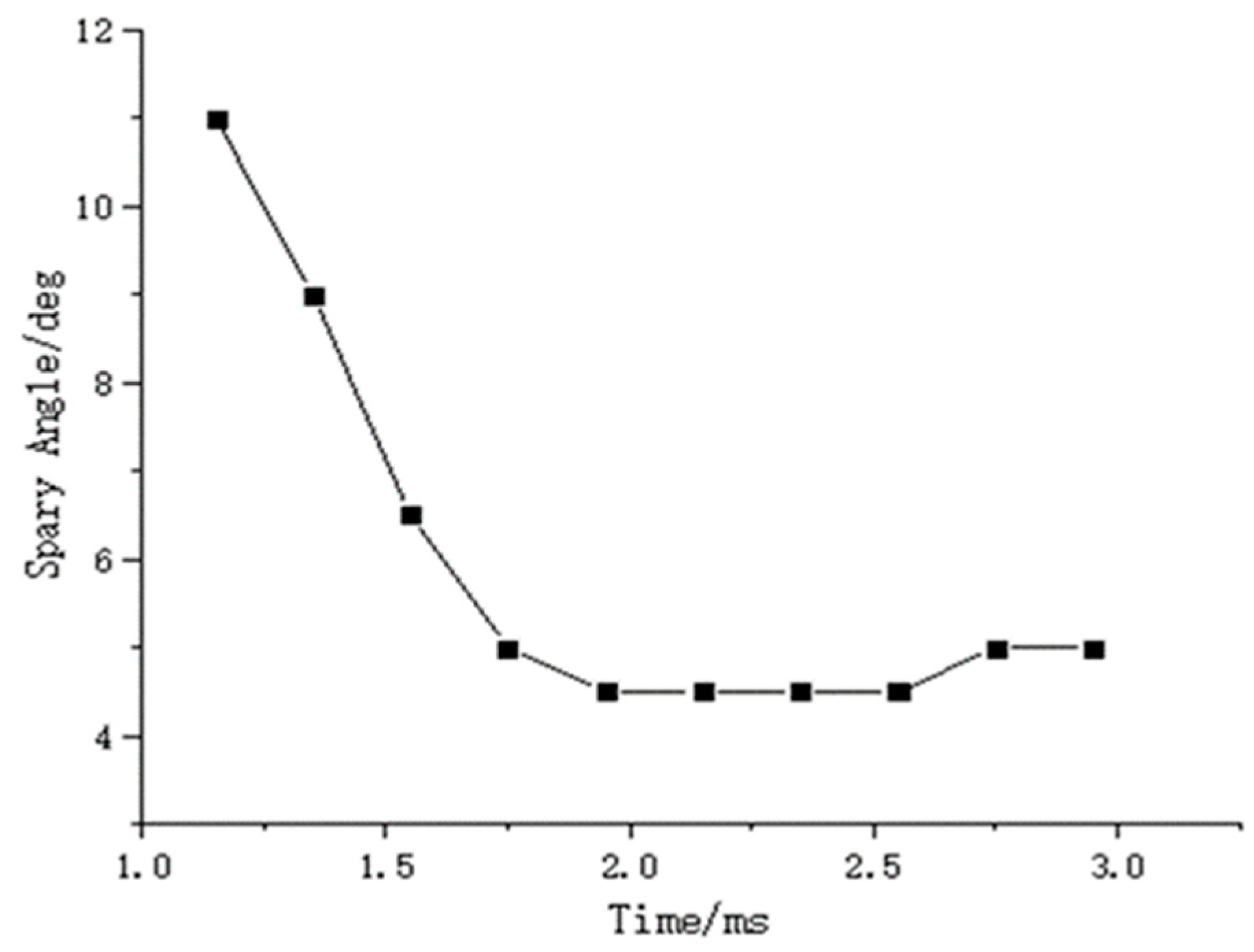
4.4. Spray Angle
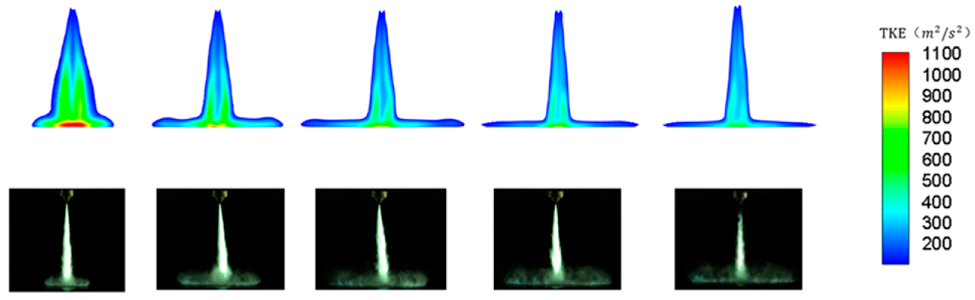
4.5. TKE Distribution
5. Conclusions
Acknowledgments
Author Contributions
Conflicts of Interest
References
- Zhu, X.; Zhao, L.; Zhao, Z.; Ahuja, N.; Naber, J.; Lee, S.Y. An Experimental Study of Diesel Spray Impingement on a Flat Plate: Effects of Injection Conditions. In Proceedings of the Ofilass-European 2017, 28th Conference on Liquid Atomization and Spray Systems, Valencia, Spain, 6–8 September 2017. [Google Scholar]
- Wang, Y.; Yang, S.; Li, B.; Zhang, Z.; Xu, J. Experiment on impingement spray characteristics of multi-hole injector in gasoline direct injection engine. J. Jiangsu Univ. 2013, 34, 390–394. [Google Scholar]
- Wei, M.R.; Liu, F.; Wen, H.; Liu, Y.C.; Zhang, Y.S. Numerical simulation and experimental research of DME spray wall-impingement. Chin. Intern. Combust. Eng. Eng. 2009, 78, 408–418. [Google Scholar]
- Kong, H.; Luo, H.; Zhang, Q.; Keiya, N. Experimental research on spray and impingement characteristics of direct injection gasoline engine. J. Yanshan Univ. 2017, 41, 13–20. [Google Scholar]
- Liu, Y.; Jia, X.; Pei, P.; Yong, L.U.; Li, Y.I.; Yan, S. Simulation and Experiment for Oxygen-enriched Combustion Engine Using Liquid Oxygen to Solidify CO2. Chin. J. Mech. Eng. 2016, 29, 188–194. [Google Scholar] [CrossRef]
- Mao, L.W.; Su, W.H.; Pei, Y.Q. Study on fuel distribution of diesel spray flat wall impingements. Neiranji Gongcheng/Chin. Intern. Combust. Eng. Eng. 2016, 37, 98–104. [Google Scholar]
- Mao, L.; Su, W.; Pei, Y. Quantitative study of impingement characteristics of diesel spray. J. Combust. Sci. Technol. 2015, 21, 521–529. [Google Scholar]
- Wang, J.G.; Wang, X.R.; Liu, J.T.; Wang, X. Effect of Injection Pressure and Ambient Pressure on Diesel Spray Characteristics. Veh. Power Technol. 2017, 2, 38–43. [Google Scholar]
- Du, W.; Lou, J.; Yan, Y.; Bao, W.; Liu, F. Effects of Injection Pressure on Diesel Sprays in Constant Injection Mass Condition. Appl. Therm. Eng. 2017, 121, 234–241. [Google Scholar] [CrossRef]
- Zama, Y.; Odawara, Y.; Furuhata, T. Experimental investigation on velocity inside a diesel spray after impingement on a wall. Fuel 2017, 203, 757–763. [Google Scholar] [CrossRef]
- Payri, R.; Salvador, F.J.; Morena, J.D.L.; Pagano, V. Experimental investigation of the effect of orifices inclination angle in multihole diesel injector nozzles. Part 2—Spray characteristics. Fuel 2018, 213, 215–221. [Google Scholar] [CrossRef]
- Song, E.; Li, Y.; Dong, Q.; Fan, L.; Yao, C.; Yang, L. Experimental research on the effect of shock wave on the evolution of high-pressure diesel spray. Exp. Therm. Fluid Sci. 2018, 93, 235–241. [Google Scholar] [CrossRef]
- Yu, S.; Yin, B.; Jia, H.; Wen, S.; Li, X.; Yu, J. Theoretical and experimental comparison of internal flow and spray characteristics between diesel and biodiesel. Fuel 2017, 208, 20–29. [Google Scholar] [CrossRef]
- Payri, R.; Gimeno, J.; Bracho, G.; Vaquerizo, D. Study of liquid and vapor phase behavior on Diesel sprays for heavy duty engine nozzles. Appl. Therm. Eng. 2016, 107, 365–378. [Google Scholar] [CrossRef]
- Roy, S.P.; Cai, J.; Modest, M.F. Development of a multiphase photon Monte Carlo method for spray combustion and its application in high-pressure conditions. Int. J. Heat Mass Transfer 2017, 115, 453–466. [Google Scholar] [CrossRef]
- Algayyim, M.S.J.; Wandel, A.P.; Yusaf, T.; Hamawand, I. The impact of n-butanol and iso-butanol as components of butanol-acetone (BA) mixture-diesel blend on spray, combustion characteristics, engine performance and emission in direct injection diesel engine. Energy 2017, 140, 1074–1086. [Google Scholar] [CrossRef]
- Pastor, J.V.; García-Oliver, J.M.; García, A.; Pinotti, M. Effect of laser induced plasma ignition timing and location on Diesel spray combustion. Energy Convers. Manag. 2017, 133, 41–55. [Google Scholar] [CrossRef]
- Li, F.; Yi, B.; Fu, W.; Song, L.; Liu, T.; Hu, H.; Lin, Q.Z. Experimental study on spray characteristics of long-chain alcohol-diesel fuels in a constant volume chamber. J. Energy Inst. 2018, in press. [Google Scholar] [CrossRef]
- Wang, Y.; Bo, L.; Li, Y.; Feng, C. Experiment and simulation of spray impingement for gasoline direct injector. J. Jiangsu Univ. 2011, 32, 410–415. [Google Scholar]
- Liu, J.; Bao, G.; Du, H.; Wang, Z.; Xu, B. Experimental study on spray and impingement characteristics of acidic oil biodiesel. J. Chin. Agric. Mech. 2016, 37, 161–165. [Google Scholar] [CrossRef]
- Pandal, A.; García-Oliver, J.M.; Novella, R.; Pastor, J.M. A computational analysis of local flow for reacting Diesel sprays by means of an Eulerian CFD model. Int. J. Multiph. Flow 2018, 99, 257–272. [Google Scholar] [CrossRef]
- Payri, R.; Viera, J.P.; Wang, H.; Malbec, L.M. Velocity field analysis of the high density, high pressure diesel spray. Int. J. Multiph. Flow 2016, 80, 69–78. [Google Scholar] [CrossRef]
- Yu, H.; Liang, X.; Shu, G.; Wang, Y.; Zhang, H. Experimental investigation on spray-wall impingement characteristics of n-butanol/diesel blended fuels. Fuel 2016, 182, 248–258. [Google Scholar] [CrossRef]
- Wang, X.; Han, Z.; Su, W. Numerical study of the impact on high-pressure and evaporating spray behavior of nozzle cavitation at typical diesel engine conditions. Int. Commun. Heat Mass Transfer 2017, 81, 175–182. [Google Scholar] [CrossRef]
- Detection, G.; Isolation, V. Reduced kinetic mechanisms of diesel fuel surrogate for engine CFD simulations. Combust. Flame 2015, 162, 3991–4007. [Google Scholar]


| Injection Conditions | Parameters | Environmental Conditions | Parameters |
|---|---|---|---|
| Fuel | Diesel | Environmental Gas | Nitrogen |
| Spray mass/mg | 25 | Ambient pressure/MPa | 1 |
| Injection pressure/MPa | 40 | Ambient temperatures/K | 723.15 |
| Injection time/ms | 4 | Hit the wall angle/(°) | 90 |
| Nozzle type | single hoe | Nozzle wall distance/mm | 40 |
| Nozzle diameter/mm | 0.26 | - | - |
| Fuel injector model | LISA |
| Evaporation model | Frossling model |
| Collision model | O’Rourke droplet collision model |
| Injection temporal type | sequential |
| Turbulence model | Reynolds Averaged N-S,RNG k- |
| C51 | C52 | C53 | Cμ | η0 | β |
|---|---|---|---|---|---|
| 1.42 | 1.68 | −1.0 | 0.0845 | 4.38 | 0.012 |
© 2018 by the authors. Licensee MDPI, Basel, Switzerland. This article is an open access article distributed under the terms and conditions of the Creative Commons Attribution (CC BY) license (http://creativecommons.org/licenses/by/4.0/).
Share and Cite
Liu, Y.; Xiang, Q.; Li, Z.; Yao, S.; Liang, X.; Wang, F. Experiment and Simulation Investigation on the Characteristics of Diesel Spray Impingement Based on Droplet Impact Phenomenon. Appl. Sci. 2018, 8, 384. https://doi.org/10.3390/app8030384
Liu Y, Xiang Q, Li Z, Yao S, Liang X, Wang F. Experiment and Simulation Investigation on the Characteristics of Diesel Spray Impingement Based on Droplet Impact Phenomenon. Applied Sciences. 2018; 8(3):384. https://doi.org/10.3390/app8030384
Chicago/Turabian StyleLiu, Yongfeng, Qi Xiang, Zhijun Li, Shengzhuo Yao, Xingyu Liang, and Fang Wang. 2018. "Experiment and Simulation Investigation on the Characteristics of Diesel Spray Impingement Based on Droplet Impact Phenomenon" Applied Sciences 8, no. 3: 384. https://doi.org/10.3390/app8030384