
Turbo Coded OFDM Combined with MIMO Antennas Based on Matched Interleaver for Coded-Cooperative Wireless Communication


College of Electronic and Information Engineering, Nanjing University of Aeronautics and Astronautics, Nanjing 210016, China
*
Author to whom correspondence should be addressed.
Information 2017, 8(2), 63; https://doi.org/10.3390/info8020063
Submission received: 22 April 2017
/
Revised: 2 June 2017
/
Accepted: 6 June 2017
/
Published: 13 June 2017
(This article belongs to the Section Information and Communications Technology)
Abstract
:A turbo coded cooperative orthogonal frequency division multiplexing (OFDM) with multiple-input multiple-output (MIMO) antennas scheme is considered, and its performance over a fast Rayleigh fading channel is evaluated. The turbo coded OFDM incorporates MIMO (2 × 2) Alamouti space-time block code. The interleaver design, and its placement always plays a vital role in the performance of a turbo coded cooperation scheme. Therefore, a code-matched interleaver (CMI) is selected as an optimum choice of interleaver and is placed at the relay node. The performance of the CMI is evaluated in a turbo coded OFDM system over an additive white Gaussian noise (AWGN) channel. Moreover, the performance of the CMI is also evaluated in the turbo coded OFDM system with MIMO antennas over a fast Rayleigh fading channel. The modulation schemes chosen are Binary Phase shift keying (BPSK), Quadrature phase shift keying (QPSK) and 16-Quadrature amplitude modulation (16QAM). Soft-demodulators are employed along with joint iterative soft-input soft-output (SISO) turbo decoder at the destination node. Monte Carlo simulated results reveal that the turbo coded cooperative OFDM system with MIMO antennas scheme incorporates coding gain, diversity gain and cooperation gain successfully over the direct transmission scheme under identical conditions.
1. Introduction
As there is an explosive increase in the utilization of wireless mobile communication, the demand for high-speed data rates among the users of 3G and 4G wireless mobile communications has increased considerably. The need to achieve a reliable communication at high data rates is challenging and is an important part of the problem in today’s rapidly developing world. The performance of high-speed wireless communication systems is limited by harsh variation in the signal strength by the phenomena commonly known as fading. Using a diversified signal processing technique in which the same signal appears in multiple instances in time, frequency or antennas that fade independently can reduce the harsh effects of fading. In recent years, a relatively new technique has emerged known as cooperative communication in a wireless system. The basic idea of this technique is that two or more than two mobile users share the same information and cooperatively communicate the information signal at a common destination. The authors in [1,2] proved, by performing rigorous information theoretic analysis, that the cooperation technique leads to higher data rate as compared to a non-cooperative counterpart. In this context, in order to exploit spatial diversity, some repetitive algorithms such as “decoded and forward (DF)” and “amplify and forward (AF)” were developed for improving the bit error rate (BER) but at the cost of reduced spectral efficiency [3]. After a year or so the same authors in [3] published a paper [4] in which they conceived the idea of user cooperation in space-time domain and developed the distributed space time coding protocol that fully exploits spatial diversity among cooperating users. After that, a slightly different framework has emerged in the literature commonly known as coded cooperation [5]. In this technique, instead of only repeating information bits, each user transmits an extra redundancy for its cooperating partner. Later this technique was also developed for multiple cooperating users [6]. The distributed coded cooperation scheme based in turbo code was originally investigated in [7]. Moreover, there has been a plethora of research on wireless cooperative communication systems using massive relays. The authors in [8] investigated the performance analysis of coded cooperation communication in cluster of relays. The authors in [9] implemented the classical Reed Muller code [10] in coded cooperation scenario over multiple relays.
In broadband wireless communication, OFDM is an effective technique that mitigates the effect of inter-symbol interference (ISI) and offers high spectral efficiency. The combination of OFDM with MIMO antennas has been very famous over the last two decades as it effectively exploits spatial and frequency diversities in frequency selective MIMO channels [11]. In order to get more benefit in terms of spatial and temporal diversities the authors in [12] have considered an application of an amplify and forward protocol in OFDM system. In [13] authors have analyzed the performance of MIMO-OFDM system in relay-assisted user-cooperative wireless communication. A coded OFDM based on time division multiple access scheme in cooperative wireless communication was investigated in [14]. This scheme is similar to the previously coded cooperative schemes [5] in which a source node broadcasts all its subcarrier towards both destination and partner user (relay) in first half of the code word in a first time slot. After successfully decoding, the partner user will re-transmit all the subcarriers to the destination in second half of the code word in a second time slot. Recently an author in [15] has investigated the performance of the OFDM system based on decode and forward cooperative communication using multiple relays over time dispersive fading channels.
Many researchers have focused their attention on developing better cooperative strategies in order to make a practical wireless standard for future wireless communication systems. Nevertheless, there has not been much work reported in the literature that exploits the basic structure of the channel code to enhance diversity through coded-cooperation. More specifically, in case of turbo code, employing good interleavers design always plays a critical role in enhancing the overall bit error rate (BER) performance of the code in a coded cooperation wireless system [16]. A plethora of research has already been done in designing suitable interleaver in [17]. Furthermore, it has been found in [18] that CMI qualifies to be an optimum choice of interleaver. The area of distributed turbo coded cooperation in a fast Rayleigh fading channels using OFDM associated with Alamouti space time block code (STBC) with code matched interleaver at the relay have been unexplored to date. This paper aims to investigate the above scenario. To the best of our knowledge the closest work to our manuscript lies in [18], where the authors proposed a modified code matched interleaver for distributed turbo coded cooperative non-OFDM systems using single antenna at each node and employed binary phase shift keying (BPSK) as the only modulation technique. However, the literature [18] did not consider the distributed turbo coded OFDM with multiple antennas at each cooperating node. It has also not considered higher-order modulation in its design. Therefore, addressing these matters are the main motivation and contribution of this manuscript.
The remaining part of the manuscript is organized as follows. Section 2 presents the basic theory of turbo coded OFDM with MIMO antennas. Section 3 discusses the brief overview of CMI. Section 4 primarily deals with proposed turbo coded OFDM with MIMO antennas scheme in cooperative scenario. Joint iterative SISO decoding for turbo coded cooperative OFDM is explained in Section 5. In Section 6, the BER performance comparison of CMI with uniform random interleaver (RI) for turbo coded OFDM with different modulation techniques over AWGN channel are discussed. Furthermore, turbo coded OFDM with MIMO (2 × 2) antennas over fast Rayleigh fading channels under different modulation schemes are also discussed. Monte Carlo simulated results of turbo coded-OFDM with MIMO (2 × 2) antennas in cooperation with different modulation schemes under CMI are presented and discussed in this section. Finally, the paper comes to an end with the conclusion drawn in Section 7.
2. Turbo Coded OFDM with MIMO (2 × 2)
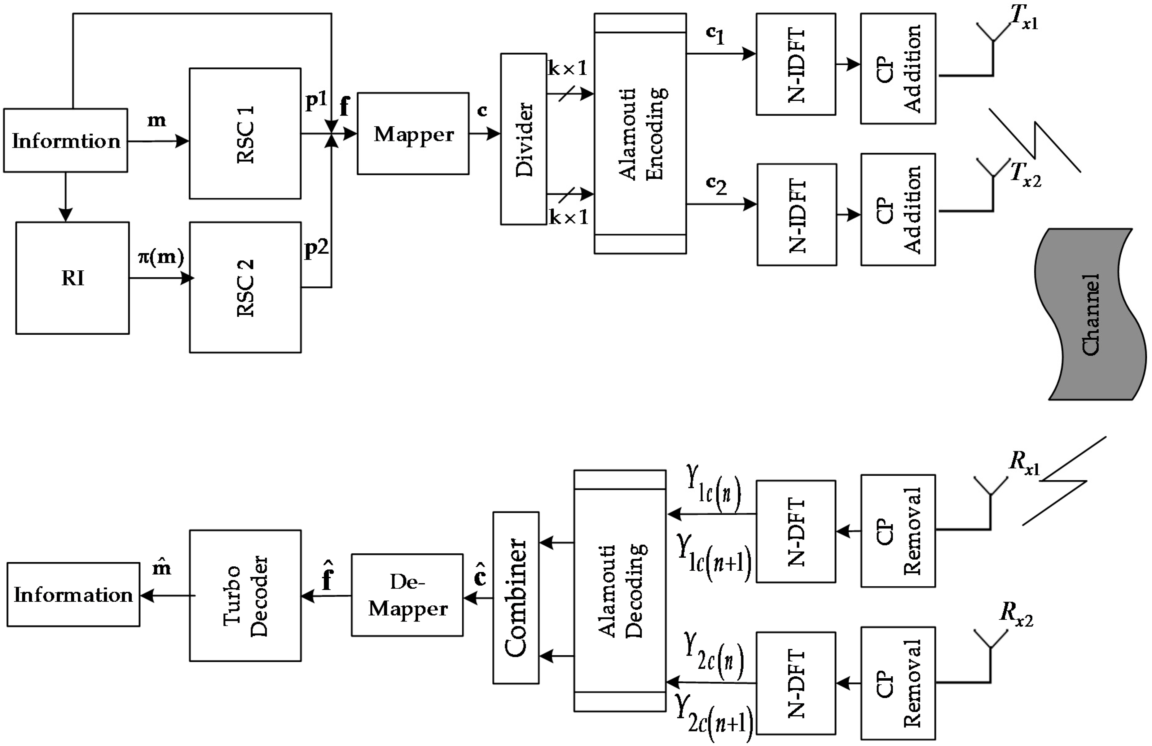
The turbo coded OFDM based on MIMO antennas is depicted in Figure 1. The information sequence of bits m is passed through recursive convolutional encoder-1 (RSC-1) that forms the parity sequences of bits p1. At the same time, information sequences of bits m are also fed into recursive systematic convolutional encoder-2 (RSC-2) via random interleaver (RI) that gives parity sequence of bits p2. The interleaver rearranges the information bits according certain design criteria. The purpose of the interleaver is to de-correlate the information bit sequence so that an iterative decoding, i.e., based on exchange of extrinsic information between the constituent decoders, can be applied [19]. The two corresponding parities sequences of bits along with information bits form the encoded turbo frame f. The encoded sequences of bits in turbo encoded frame f are mapped into a mapper that generates digitally modulated complex symbols c, i.e., QPSK, 16 QAM etc. Then, Alamouti encoding [20] is applied to obtain the two parallel encoded signals and . At time slot 1 and 2 (i.e., and where T is OFDM symbol time) and are sent in two parallel paths, respectively. Then N-point inverse discrete Fourier transform (IDFT) operation is applied to these sequences of symbols, which transforms the corresponding signal in time-domain. Finally, a cyclic prefix is appended to get corresponding OFDM symbols, which are transmitted with the antenna and antenna respectively via fast frequency selective Rayleigh fading channel H. The insertion of a cyclic prefix transforms the linear convolution operation into circular convolution operation. A well-known property of the DFT is that circular-convolution in time-domain results in multiplication in frequency-domain. Moreover, it is assumed that channel entries do not change for two consecutive Alamouti space-time block codes. Therefore, the channel qualifies to be called a fast Rayleigh fading channel. Also, the transmitter does not know the about channel entries and receiver has a full knowledge about channel H.
The received signal after removal of cyclic prefix and N-DFT operation at time slot 1 and time slot 2 are modeled as follows:
where the operator “” denotes the circular convolution. and are the corresponding frequency domain representation of and respectively. The subscript c of , , and represents the combined received signal at receive antenna1 , receive antenna2 in time slot-1 and time slot-2 respectively. The terms such as , , and are the noise terms of antenna of receive antenna1 , receive antenna2 in time slot 1 and time slot 2 respectively. Thus, the received signal vectors are obtained in Equations (1)–(8). Moreover, represents channel impulse response from transmit antenna1 to the received antenna1 , represents channel impulse response from transmit antenna1 to the received antenna2 , represents channel impulse response from transmit antenna2 to the received antenna1 and represents channel impulse response from transmit antenna2 to the received antenna2 . Subsequently , , and are diagonal matrix whose diagonal entries are DFTs of the corresponding channel impulse response. Now the Alamouti STBC decoding in frequency domain is given as follows:
The estimated signals i.e., and are combined to get the signal . The signal is given as input to the de-mapper that performs the corresponding demodulation process to obtain the estimated sequence of soft bits . Finally, joint turbo decoding is performed to get final estimation of information sequences . The details of joint turbo decoding will be discussed in the subsequent section of this manuscript.
3. Code Matched Interleaver (CMI)
The performance of any coded-cooperative system depends on the construction of a better code at the destination node. A code is better or not it depends on its distance spectrum properties, which will directly affect its error capability. Turbo code is considered to be a better code mainly because of good distance properties and its convenient structure that can be effectively deployed in cooperative scenarios due to its particular distributive nature in its encoding scheme. Once the turbo code is distributed for coded cooperation, the interleaver is usually placed in the relay node, which is situated near to the destination. Furthermore, if the relay has to contribute in obtaining a better code at the destination then it must generate high weight code words. The high weight code words can only be generated if the interleaver is well capable of breaking the low weight code words into high weight code words. The only interleaver that fully accomplishes this task is the code-matched interleaver (CMI) [17]. The CMI interleaver matches the distance spectrum of the constituent code. At low to medium SNR regime (0–3 dB) the interleaver size plays an effective role in improving the performance of the turbo code. However, at medium to high SNR regime (3–8 dB), the spectral lines of constituent encoders determine the performance the turbo code. CMI eliminates the first few spectral lines of distance spectrum thereby causing an increase in its code free distance . As a result, the code performance at high SNR regime is improved considerably.
In distributed turbo code, the performance of iterative decoders is also a crucial factor that affects the BER performance of the cooperative communication. The effective exchange of extrinsic information in the iterating decoding is heavily dependent on free distance of the turbo code. The lower free distance will degrade the performance of iterative decoding in cooperative communication at the destination. At high SNR, the BER curve saturates and becomes flat. This action is called an “error floor” [21]. CMI breaks the low weigh information code word that would have formed if any other interleaver might have used. Thus, CMI causes a lower error floor region (due to the minimum free distance). The details of the construction of CMI are presented in [17]. However, we briefly discuss the construction of CMI in this section.
Let us consider two identical 4-state recursive systematic convolutional encoders each having a generator matrix where is feed forward polynomial and is feedback polynomial. The information sequence is encoded by RSC-1 that results in pair, where is the parity sequence. After the interleaving the information sequences , the interleaved information sequence is passed to RSC-2 that generates pair, where is another parity sequence. Let be the weight of the information sequence and likewise and be the weights of the corresponding parity sequences produced by RSC-1 and RSC-2 respectively. Then, the net weight of the turbo code can be written as follows
The low weight-2 input sequence, which is responsible for low weight code word can be represented by the following polynomial equation:
where k1 = 1, 2, 3, … is a positive integer, α is the minimum distance between “1”s in weight-2 information sequence , is the time delay, = 1, 2, 3 …. The interleaved information can also be represented in polynomial form.
where k2 = 1, 2, 3, … is a positive integer, is the time delay, such that = 1, 2, 3 …. Let be the minimum parity check sequence generated by a weight-2 input sequence. Then the weight of j-th parity bit sequence is given as follows:
where = 1, 2, 3, 4 …, j = 1, 2. The net weight of the turbo code generated by weight-2 input sequences is given as:
Suppose that the positions of “1”s in weight-2 information sequence are denoted by , . The information sequence after passing through interleaver scrambles the bits. The new position of “1”s becomes as shown in Figure 2.
Let’s take the most damaging case for weight-2 information sequence as
This case is the worst case because spacing between the consecutive two “1”s between the original and the interleaved sequences are both multiple of . This will cause the interleaved information sequence still divisible by RSC-2 that will eventually result in low parity weight sequences. Thus, the net weight of turbo code word will be lowered and will decrease the overall performance of turbo code. Therefore, to prevent this worst-case scenario to happen, the interleaver must meet the following design mapping criteria:
However, not all the weight-2 input sequences are bad only those weight-2 input pattern that produce low weight code words that severely affects the BER performance should be removed in the interleaver design. Therefore a parameter, commonly known as threshold is usually defined where represents weight-2 or weight-4 sequences. If the weight of the code word lies outside the threshold value , then that particular weight-2 sequence is not considered as bad pattern and interleaver must not remove that input pattern. The details of threshold are presented in [16]. The value of threshold varies for each turbo code. Applying threshold to Equation (13) we obtain the following inequality
Thus, the weight-2 information sequence is considered to be a bad sequence if it satisfies (17) and (20) simultaneously. The weight-3 information sequences, which result in low weight turbo code word is effectively removed by using S random constraint condition. The design steps of S-random interleaver are well formulated in [21]. We also consider a weight-4 sequence, which usually produces low weight parity sequence that degrades the performance of overall turbo code. A weight-4 sequence becomes weight-2 error pattern after interleaving which also produces bad weight code word. By same procedure, as weight-2 sequence, the new weight generated by weight-4 input sequence can be expressed as follows:
Suppose that the positions of “1”s are represented by , , and for weight-4 information sequence where, as . The information sequence is passed through an interleaver then positions of “1”s in the interleaved sequence is denoted by and . The scenario is depicted in Figure 3. The worst case for weight-4 information sequence is given as follow:
OR
However such a bad scenario can be avoided if the interleaver incorporates the following mapping criterion
OR
As mentioned earlier that not all the weight-2 sequences are bad, the same is the case with weight-4 sequences. There are such a weight-4 sequences which does not satisfy (23) but still they are not considered as bad sequences. Similarly, there is a threshold parameter in given [16]. Applying this parameter to the weight-4 input sequences results in the following inequality
The weight-4 sequence will only be classified as bad weight-4 sequence if and only if it satisfies both the inequality (23) and (25) simultaneously. Otherwise weight-4 sequence will not degrade the performance of turbo code. The effect of input sequence with input weight w > 4 on over all turbo code performance is very negligible. Therefore, we will not consider them in the interleaver design.
A four–state turbo code having two identical recursive systematic convolutional encoders each with generator polynomial is considered in this manuscript. The values of threshold parameters such as , and are found in [21]. The parameters values are and . The weight-2 information sequence that causes minimum parity sequence is given as (…010010…). The parity sequence that is produced by considered weight-2 information sequences by RSC-1 is given as (…011110…). The value of and is considered for this specific code. To design CMI all the design mapping criteria that were aforementioned in this section must be taken into an account.
4. Turbo Coded OFDM with MIMO Antennas in Cooperation
The concept of wireless communication based on three terminal networks using OFDM over frequency selective fading channels can be found in the excellent tutorial survey article detailed in [22]. The three terminals are source-S, relay-R, and destination-D, as shown in Figure 4.
The whole code is divided in two codes C1 and C2. C1 is placed at source-S and C2 is placed in relay-R. The relay-R is mostly located near to destination-D. The whole transmission from source-S to destination-D is accomplished in two time slots. In first time slot the source-S encodes the information sequence of bits through code C1 and broadcast it towards both relay-R and destination-D. After, the corresponding de-modulation, the relay-R receives the signal in first time slot. The relay-R decodes the information sequence. Usually this decoding is assumed to be an ideal decoding due to the assumption that source-S to relay-R channel is completely noiseless. Moreover, the Relay-R encodes the information sequences with other code C2 and re-transmits them to the destination-D through a Rayleigh fading channel in second time slot after modulation. Finally, the received signals from the source-S and relay-R are demodulated by soft input soft output SISO demodulator and is estimated using joint iterating decoding employed at the destination-D.
The way the turbo code is structured makes it suitable for its deployment in coded cooperative scenario. Turbo code is disturbed to source-S and relay-R in such way that the cooperation between theses nodes takes place. It forms an important class of cooperative communication commonly known as distributed turbo codes (DTC) [5].
The turbo coded OFDM with MIMO antennas are deployed in a cooperation communication scenario as shown in the Figure 5. The scheme completes the transmission of one turbo coded OFDM frame in two time slots. The source-S node consists of 1/2 rate RSC-1 encoder, mapper, OFDM block and Alamouti STBC. The information sequence of bits is applied to RCS-1 encoder that transforms the information sequences of bits into coded sequences of bits q. The coded sequence of bits q consists of information sequence of bits and parity sequence of bits . The coded sequences of bits q are mapped into complex symbols a using different constellations such as BPSK, QPSK and 16QAM. The coded symbols a takes the form of RSC-1 encoded OFDM symbols as they are passed through OFDM block by incorporating N-point IDFT and appending cyclic prefix. The RSC-1 encoded OFDM symbols are given as input to Alamouti Space time block code. Alamouti encoding [20] is applied to RSC-1 encoded OFDM symbols that will result in two parallel sequences and . These two Alamouti code words are broadcasted over the radio frequency (RF) channel towards both relay-R and destination-D. The signal received at the destination D during the first time slot is modelled as
where
is the Alamouti space time code word, is the channel matrix between source-S and destination node. The channel matrix is assumed to be a Rayleigh fading channel whose entries are independent and identically distributed (I.I.D) complex Gaussian random variables with zero mean and variance ½ per dimension. is the complex Gaussian noise matrix whose entries are modelled as I.I.D complex Gaussian random variables with zero mean and variance N0/2 per dimension. The channel entries remain static during the transmission of one complete Alamouti STBC. Therefore, the channel qualifies to be called as fast Rayleigh fading channel. At the same time, in first time slot the signal received at the relay-R is modeled as
where is the Alamouti space time code word and channel matrix and Gaussian noise matrix defined similarly as and respectively. The received signal is decoded using Alamouti decoding [19].
The signal is passed through OFDM decoder and corresponding soft demodulator to estimate the original information sequence . The estimated information sequence may or may not be same as original information sequence . It depends upon the source-S to relay-R channel. The estimated information sequence is interleaved by CMI that permutes the estimated information sequence in an optimum way. The relay-R encodes the interleaved estimated information sequence using RSC-2 encoder. The RSC-2 encoded sequences of parity bits are mapped into digital modulator to obtain the complex digital modulated symbols b. The RSC-2 encoded symbols b is delivered to OFDM block which takes N point IDFT and appends a cyclic prefix to form RSC-2 encoded OFDM symbol . The resulted RSC-2 encoded OFDM symbol is again given as input to Alamouti STBC which results in two parallel sequences and . These two Alamouti code words are propagated towards destination-D according to Alamouti encoding scheme [20]. The signal received at the destination-D during the second time slot is modelled as follows as:
where and are channel matrix and Gaussian noise matrix respectively and are defined similarly as and .
The received signals and are delivered to Alamouti STBC decoder and OFDM demodulator in their respected time slots. OFDM demodulator takes N-point DFT and removes the cyclic prefix to form the complex symbols. These complex symbols are digitally demodulated by SISO demodulator. SISO demodulator produces log likelihood ratios (LLRs) for each of the received coded bits. These soft bit LLRs for first and second time slot are given an input to joint iterative turbo decoder, which iterates for a desired number of iterations and pass the updated LLRs to the slicer. The term joint here refers to the fact the decoding of the signals and are performed together rather than decoding each of the received signal separately. The joint iterative turbo decoding for the proposed scheme is comprehensively discussed in the subsequent section of the manuscript. In the end the slicer performs the hard decoding operation on each received soft bit to recover the original transmitted sequence of information bits .
The source-S node transmits M1 code word bits (RSC-1 encoded OFDM code word) during first time slot to decoder 1 (as it corresponds to the RSC-1 encoder at the source-S) and relay-R node transmits M2 code word bits (RSC-2 encoded OFDM code word) during the second time slot to decoder 2 (as it corresponds to the RSC-2 encoder at the relay-R). The total code word bits reach at the destination during one complete transmission is M = M1 + M2. Thus, the code rate for the proposed scheme is given as follows:
where is 1/3 for the proposed coded cooperative scheme.
5. Joint Iterative Decoding for the Proposed Scheme
The joint iterative SISO turbo decoding for the proposed scheme is depicted in the Figure 6. The design of SISO de-mapper for iterative turbo codes has been reported in [18]. The joint decoder is primarily composed of two different SISO decoders, one for each recursive systematic convolutional encoder. Each SISO decoder accepts three inputs and delivers one output. The input of the SISO decoder consists of LLRs of information bit, parity bits and LLRs of a priori information bits and it outputs an extrinsic information and for systematic and parity received bits, respectively.
In first time slot, the soft de-mapper produces LLRs , these LLRs are soft-demodulated sequence of bits that corresponds to information and parity sequence of bits, after OFDM and Alamouti space time block encoding, which were initially originated from source node by RSC-1 encoder. The de-multiplexer divides the LLRs into two distinct streams such as sequence of information bit LLRs and sequence of parity bit LLRs . These LLRs are delivered to SISO decoder 1 as its both inputs that generates extrinsic information sequence of bits . The extrinsic information sequence of systematic bits is passed to CMI. This interleaved extrinsic information bits is given as a-priori input to SISO-decoder-2.
In second time slot, the second soft de-mapper outputs the soft LLRs . These LLRs are soft-bits that correspond to parity bits of RSC-2 encoder, which were transmitted from relay node. SISO-decoder-2 produces extrinsic information such as and that corresponds to sequence of information and parity bits, respectively. The extrinsic information of information bits is de-interleaved and is given back to SISO-decoder-1 while the extrinsic information of parity bits is ignored. The extrinsic information of corresponding information sequence of bits are interchanged between the constituent SISO-turbo decoders for a desired number of iterations. Finally, the extrinsic information and are added in summer block and is provided to the slicer through a de-interleaver. The slicer will perform hard decoding operation to estimate the information sequence of bits that completes the transmission process.
6. Results and Discussion
This section discusses the Monte Carlo simulated results of turbo coded OFDM with MIMO antennas scheme in cooperation over fast Rayleigh fading channels. The performance of CMI has been evaluated under turbo coded OFDM with MIMO (2 × 2) scheme over fast Rayleigh fading channels. Moreover, the performance of CMI has also been evaluated in turbo coded OFDM scheme over AWGN channel. For a fair comparison among the proposed schemes, the code rate is kept constant as 1/3. The generator matrix is taken as . The turbo decoding algorithm is chosen as Log-MAP for all the simulations. The length of CMI is taken as 1024 bits, which are used, in coded-cooperative schemes. For all coded-cooperative simulations, the S-R channel is assumed to be perfect . Moreover, the relay-R node is placed near to the destination node therefore it has been given 1 dB additional gain in SNR over source-S node. It has assumed that channel response is already known at the destination-D. The delay spread of fast Rayleigh fading channels is taken as 9 bits. Furthermore, the channel remains constant for two consecutive OFDM frames. The size N of OFDM block is chosen as 64, and 15 percent of the N samples are used as the cyclic prefix. The modulation schemes chosen in all the simulation are BPSK, QPSK, and 16QAM. Moreover, signal constellation with gray mapping in employed in all the simulations.
6.1. Performance Comparison between CMI and RI for Turbo Coded OFDM in AWGN Channel
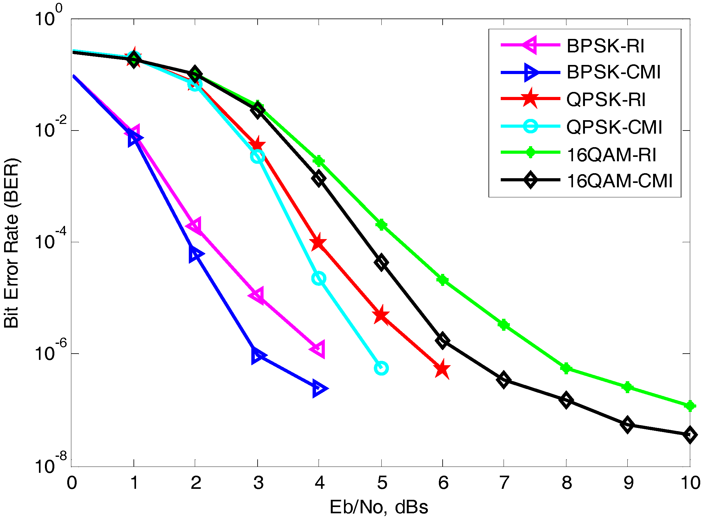
The CMI is designed for turbo coded OFDM scheme. The size of interleaver L is taken as 256 bits. The joint turbo decoding iterations are taken as four in all the simulated results in order to have a fair comparison. The bit error rate (BER) performance of turbo coded OFDM scheme over AWGN channel is estimated by Monte Carlo simulations as shown in Figure 7. The CMI is compared with RI over different modulation schemes such as BPSK, QPSK and 16QAM. It is evident from Figure 7 that a CMI interleaver not only improves the performance of code in medium to high SNR regime but also lowers the bit “error floor” performance significantly. Comparing the simulation results for four-state turbo coded OFDM in BPSK modulation scheme it was observed that the CMI achieves an improvement of 1-dB relative to RI at BER of 10−6. Similarly it was observed that CMI out performs its counterpart RI by 1-dB for the same BER in case of QPSK modulation. In the case of 16QAM, the gap between CMI and RI widens as the SNR increases. This gap widens to its maximum value at the BER of 8 × 10⁻⁸. At this BER the CMI achieves a gain of 1.5 dB relative to its counterpart RI. Moreover, an error floor performance has been improved considerably in the case of CMI. Furthermore, it is also observed that as the order of modulation increases, the BER performance decreases significantly. As seen from the figure a low-order modulation such as BPSK is more resilient and can tolerate a large amount of noise interference as compared to high-order modulation such as 16QAM which is more sensitive against bit errors, it can only be useful when the SNR is sufficiently high and the communication system is bandwidth efficient.
6.2. Performance Comparison between CMI and RI for Turbo Coded OFDM with MIMO (2 × 2) Antennas in Fast Rayliegh Fading Channels
The performance CMI is also analyzed and evaluated under turbo coded OFDM in MIMO antennas scheme over fast Rayleigh fading channels. The said scheme incorporates two transmit antennas at the source-S terminal and two receive antennas at the destination-D terminal. The interleaver size L is taken as 1024 bits. The decoding iteration is taken as four in all the simulated results. The BER performance of turbo coded OFDM in MIMO antennas scheme with CMI and RI is simulated over a fast Rayleigh fading channel as shown in Figure 8. The performance of the selected CMI is evaluated on turbo coded OFDM with MIMO (2 × 2) scheme. The digital modulation techniques are chosen as BPSK, QPSK, and 16QAM. Comparing the simulation results for 4-state turbo coded OFDM with MIMO (2 × 2) in BPSK modulation scheme it has been seen that the CMI achieves an improvement of 1.2 dB relative to RI at BER of 10−7 over fading channels.
Both the interleavers achieve “error floor”. However, in the case of CMI, the error floor performance has been improved significantly. Similarly, the BER performance of the considered scheme incorporating CMI outperforms RI in QPSK modulation over fading channels. It was observed that CMI performs better especially in medium to high SNR regime (3–6 dB) as compared with its counterpart RI. In this case, CMI achieves 1 dB gain in SNR relative to RI at the BER of 10−6. Moreover, the waterfalls region exhibits steeper slope. This is due to fact that CMI ensures that no short cycle events occur. In the case of 16QAM a similar behavior was observed. An interesting observation is seen from the Figure 8 that the BER performance of the proposed scheme with CMI always decreases rapidly with the increasing SNR. This is due to the fact the CMI increases the minimum free distance of the turbo code which eventually results in the reduced error floor of the code.
6.3. Performance Comparison of Turbo Coded OFDM with MIMO (2 × 2) Antennas in Coded Cooperation
The Monte Carlo simulated results of turbo coded OFDM with MIMO (2 × 2) scheme in cooperation is shown in Figure 9. In coded cooperation the relay-R has been given an additional gain of 1 dB relative to source-S. The S-R channel is assumed to be an ideal channel i.e., complete noise less channel. The CMI of length L = 1024 bits is applied to both cooperation and noncooperation (turbo coded OFDM with MIMO (2 × 2)) schemes. The code rate for both the compared schemes are kept as 1/3.
The turbo coded cooperative OFDM with MIMO (2 × 2) scheme in BPSK outperforms its counterpart non-cooperative scheme under identical conditions as expected. The proposed cooperative scheme in BPSK achieves a significant gain of 1.5 dB at BER of 2 × 10⁻⁸ over its non-cooperation counterpart. Both the schemes effectively reach their error floor region due to the insertion of the CMI. However, the proposed cooperation scheme with the CMI reaches the error floor at BER of 9 × 10⁻⁸ which signifies its improvement in error floor region. Similarly, the turbo coded cooperative OFDM with MIMO (2 × 2) scheme with QPSK modulation performs better than its counterpart in non-cooperative scheme. The proposed cooperative scheme achieves 1 dB gain in SNR at the BER of 5 × 10⁻⁷ relative to non-cooperative scheme with QPSK modulation. The proposed cooperative scheme in 16QAM modulation achieves 1 dB gain in SNR relative to its counterpart non-cooperative scheme. The BER curve of the cooperation scheme exhibits steeper behavior than those of non-cooperation scheme. The performance can be further improved with an increase in the SNR. The improvement in BER is due to the fact the large diversity gain has achieved in the proposed cooperation scheme that contributes to the low bit error performance as the SNR increases.
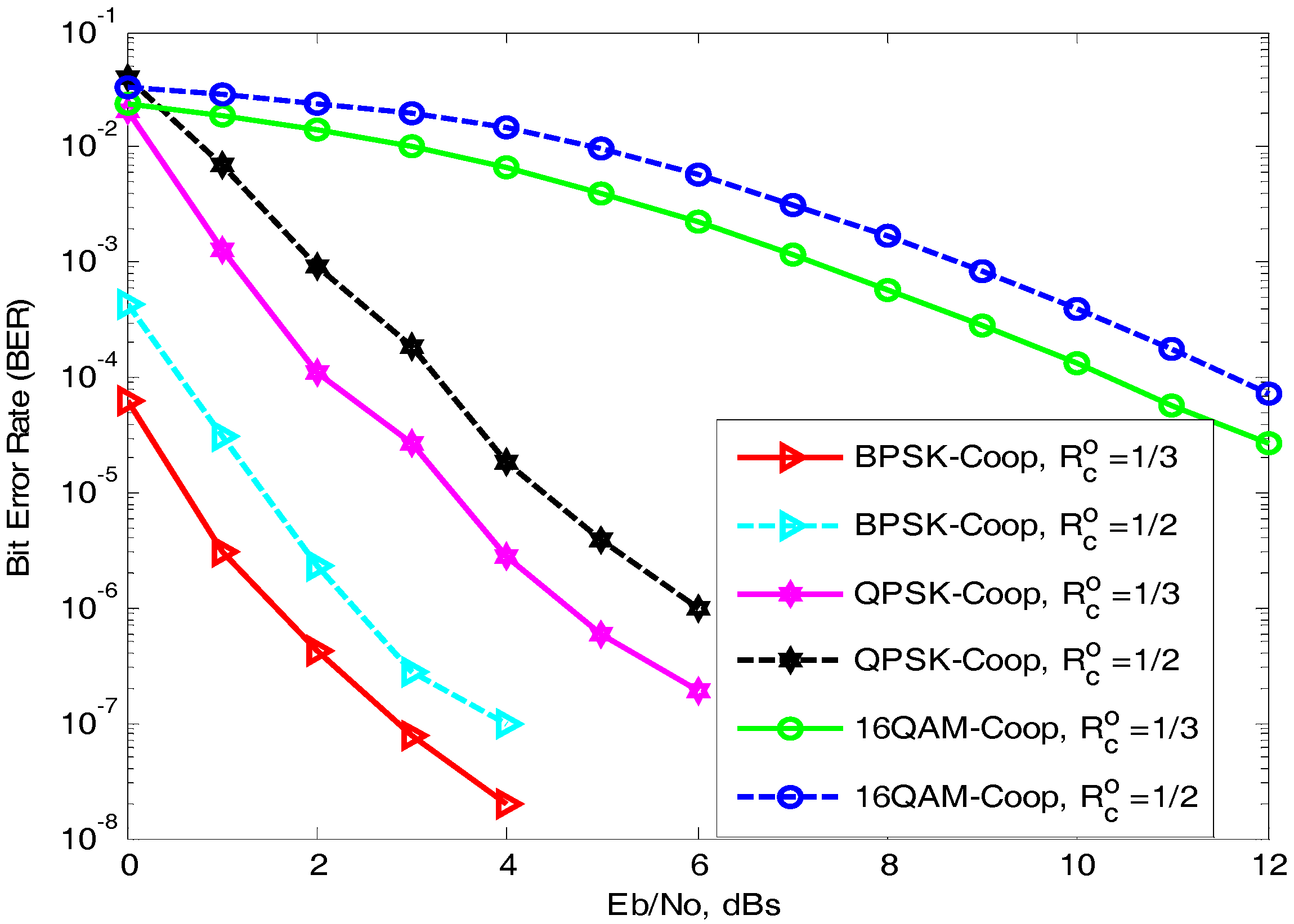
The Figure 10 presents Monte Carlo simulated BER performance comparison of our proposed coded cooperative scheme under different code rates. More specifically, the CMI-based turbo coded cooperative OFDM with MIMO (2 × 2) antennas scheme is punctured to achieve the half code rate i.e., . Thus, the BER performance of our coded cooperative scheme reduces roughly by 1 dB. As in the case of punctured coded cooperative scheme, the puncturing operation takes only one parity bit at a time and discards other parity bit [16]. Therefore, the BER performance of punctured turbo coded cooperative OFDM with MIMO antennas scheme is reduced significantly. However, by reducing the code rate the overall latency and the bandwidth of the transmission system is improved.
7. Conclusions
In this paper, we analyzed a scheme for high data rate wireless communication system. The considered scheme incorporates turbo coded OFDM with Alamouti STBC. A CMI is specially deployed to further enhance the turbo code performance. The performance of the CMI is analyzed and evaluated on the turbo coded OFDM with MIMO antennas scheme. Furthermore, the selected scheme is effectively extended in cooperative communication scenarios. The scheme in cooperative communication incorporates coding gain, diversity gain, multiplexing gain and cooperation gain successfully. The Monte Carlo simulated result validates the performance of proposed scheme in cooperative communication scenario. Moreover, the performance of the proposed cooperation scheme can be further improved by employing multiple relays. Massive antennas at the destination can be deployed to further reduce probability of errors. Therefore, deploying higher STBCs in the distributed cooperative diversified manner is practical and is a promising feature for future generation wireless communication systems.
Acknowledgments
The authors would like to thank the anonymous reviewers for their precious suggestions, comments and reviews that help in improving the quality of this manuscript.
Author Contributions
Rahim Umar conceived the idea. He developed the mathematical models and performed the Monte Carlo simulations. Fengfan Yang checked the mathematical model and the simulated results. Shoaib Mughal revised the manuscript. All authors have read and approved the final version of manuscript before its first submission to a journal.
Conflicts of Interest
The authors declare no conflict of interest.
References
- Sendonaris, A.; Erkip, E.; Aazhang, B. User cooperation diversity. Part I. System description. IEEE Trans. Commun. 2003, 51, 1927–1938. [Google Scholar] [CrossRef]
- Sendonaris, A.; Erkip, E.; Aazhang, B. User cooperation diversity. Part II. System description. IEEE Trans. Commun. 2003, 51, 1939–1948. [Google Scholar] [CrossRef]
- Laneman, J.N.; Tse, D.N.; Wornell, G.W. Cooperative diversity in wireless networks: Efficient protocols and outage behavior. IEEE Trans. Inf. Theory 2004, 50, 3062–3080. [Google Scholar] [CrossRef]
- Laneman, J.N.; Wornell, G.W. Distributed space-time-coded protocols for exploiting cooperative diversity in wireless networks. IEEE Trans. Inf. Theory 2003, 49, 2415–2425. [Google Scholar] [CrossRef]
- Hunter, T.E.; Nosratinia, A. Diversity through coded cooperation. IEEE Trans. Wirel. Commun. 2006, 5, 283–289. [Google Scholar] [CrossRef]
- Zummo, S.A. Performance analysis of coded cooperation diversity in wireless networks. Wirel. Commun. Mobile Comput. 2007, 7, 473–481. [Google Scholar] [CrossRef]
- Zhang, Z.; Duman, T. Capacity-approaching turbo coding for half-duplex relaying. IEEE Trans. Commun. 2007, 55, 1895–1906. [Google Scholar] [CrossRef]
- Wang, D.; Hao, L. Performance analysis for cooperative relay communication. Wirel. Pers. Commun. 2013, 71, 1619–1631. [Google Scholar] [CrossRef]
- Ejaz, S.; Yang, F.; Xu, H.; Zhang, S. Jointly optimized multiple Reed-Muller codes for wireless half-duplex coded-cooperative network with joint decoding. EURASIP J. Wirel. Commun. Netw. 2015, 14, 115–754. [Google Scholar] [CrossRef]
- Ejaz, S.; Yang, F. Jointly Optimized Reed-Muller Codes for Multi-Level Multi-Relay Coded-Cooperative VANETS. IEEE Trans. Veh. Technol. 2016, 1–8. [Google Scholar] [CrossRef]
- Su, W.; Safar, Z.; Olfat, M.; Liu, K.R. Obtaining full-diversity space-frequency codes from space-time codes via mapping. IEEE Trans. Signal Process 2003, 51, 2905–2916. [Google Scholar] [CrossRef]
- Yatawatta, S.; Petropulu, A.P. A multiuser OFDM system with user cooperation. In Proceedings of the 2004 Asilomar Conference on Signals, Systems and Computers, Pacific Grove, CA, USA, 7–10 November 2004; pp. 319–323. [Google Scholar] [CrossRef]
- Mheidat, H.; Uysal, M.; Al-Dhahir, N. Distributed space-time block coded OFDM for relay-assisted transmission. In Proceedings of the 2006 IEEE International Conference on Communications, Istanbul, Turkey, 11–15 June 2006; pp. 4513–4519. [Google Scholar] [CrossRef]
- Lin, J.C.; Stefanov, A. Cooperative coding for OFDM systems. Wirel. Pers. Commun. 2007, 43, 123–139. [Google Scholar] [CrossRef]
- Agarwal, A.; Varshney, N.; Jagannatham, A.K. Performance analysis of multi-relay selective DF based OFDM cooperative systems over time selective links with imperfect CSI. In Proceedings of the IEEE Region 10 Conference, Marina Bay Sands, Singapore, 22–25 November 2016; pp. 3220–3223. [Google Scholar] [CrossRef]
- Soliman, T.H.; Yang, F.; Ejaz, S. Interleaving gains for receive diversity schemes of distributed turbo codes in wireless half–duplex relay channels. Radioengineering 2015, 24, 481–488. [Google Scholar] [CrossRef]
- Feng, W.; Yuan, J.; Vucetic, B.S. A code-matched interleaver design for turbo codes. IEEE Trans. Commun. 2002, 50, 926–937. [Google Scholar] [CrossRef]
- Ejaz, S.; Yang, F. Turbo codes with modified code matched interleaver for coded-cooperation in half-duplex wireless relay networks. Frequenz 2015, 69, 171–184. [Google Scholar] [CrossRef]
- Benedetto, S.; Montorsi, G. Unveiling turbo codes: Some results on parallel concatenated coding schemes. IEEE Trans. Inf. Theory 1996, 42, 409–428. [Google Scholar] [CrossRef]
- Alamouti, S.M. A simple transmit diversity technique for wireless communications. IEEE J. Sel. Areas Commun. 1998, 16, 1451–1458. [Google Scholar] [CrossRef]
- Perez, L.C.; Seghers, J.; Costello, D.J. A distance spectrum interpretation of turbo codes. IEEE Trans. Inf. Theory 1996, 42, 1698–1709. [Google Scholar] [CrossRef]
- Zhang, J.; Yang, L.; Hanzo, L.; Gharavi, H. Advances in Cooperative Single-Carrier FDMA Communications: Beyond LTE-Advanced. IEEE Commun. Surv. Tutorials 2015, 17, 730–756. [Google Scholar] [CrossRef]
Figure 1.
Block diagram of turbo coded OFDM with MIMO (2 × 2) antennas.

Figure 2.
Weight-2 information sequence is mapped to weight-2 information sequence with similar pattern after permuted through interleaver.
Figure 2.
Weight-2 information sequence is mapped to weight-2 information sequence with similar pattern after permuted through interleaver.
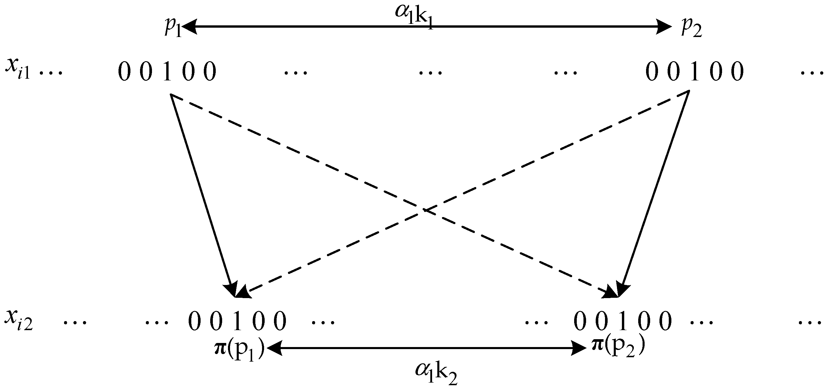
Figure 3.
Weight-4 information sequence is mapped to weight-4 information sequence with similar pattern after permuted through interleaver.
Figure 3.
Weight-4 information sequence is mapped to weight-4 information sequence with similar pattern after permuted through interleaver.
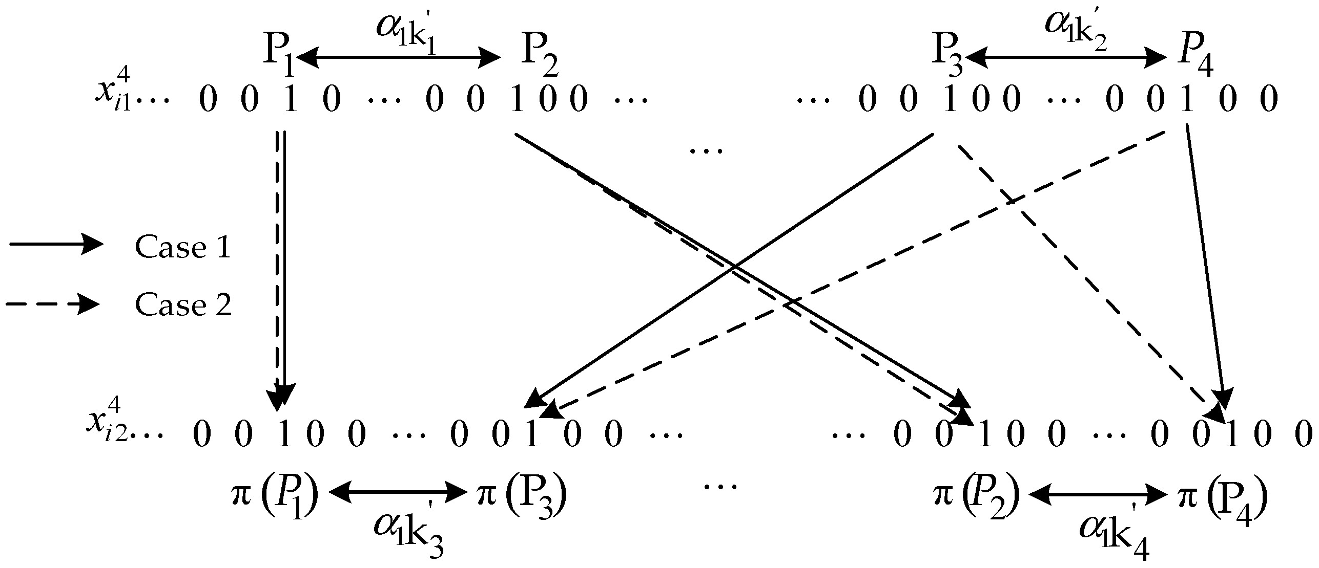
Figure 4.
Three-terminal coded-cooperation communication model.
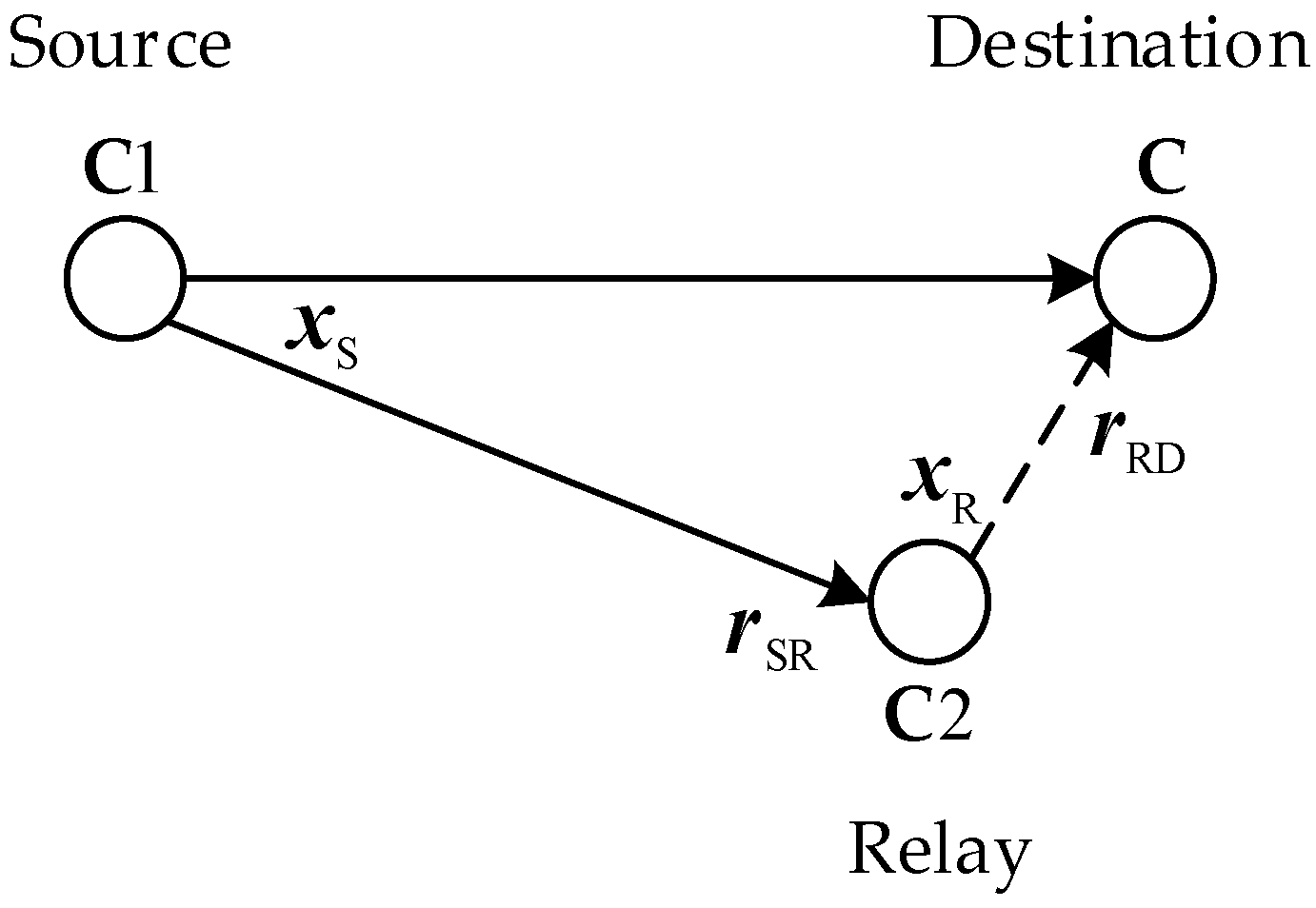
Figure 5.
Distributed turbo coded OFDM with MIMO (2 × 2) antennas.
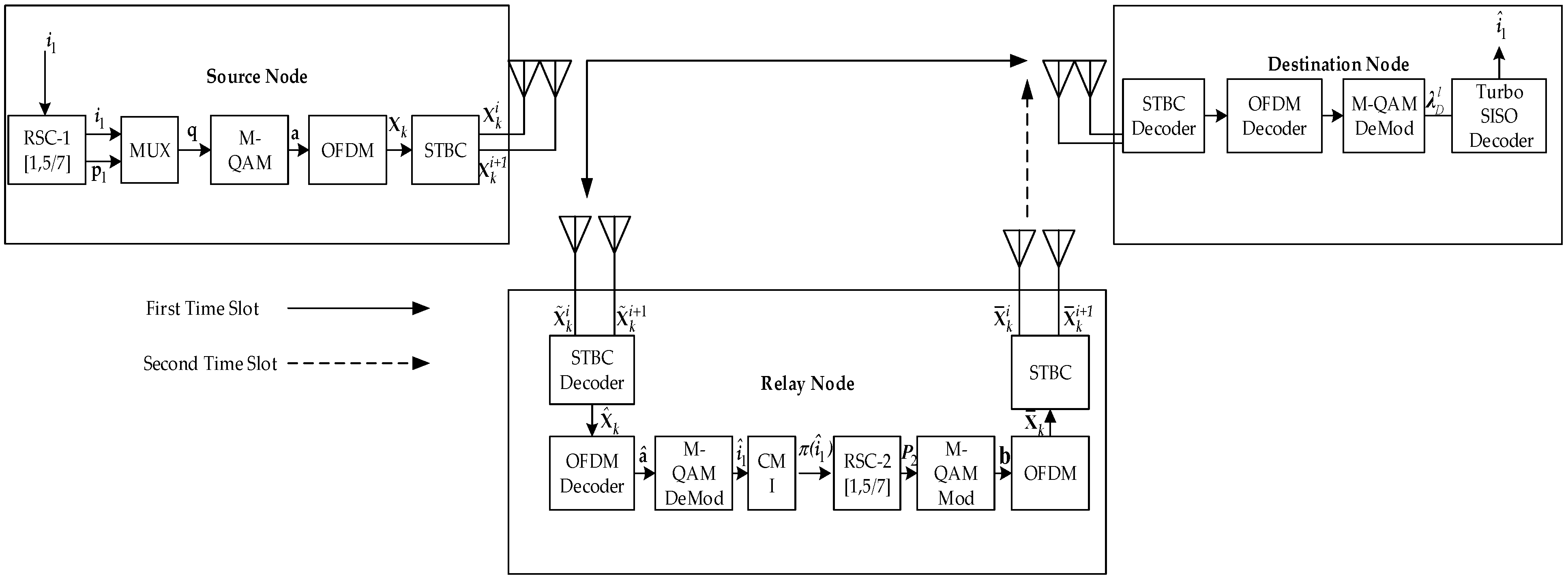
Figure 6.
Joint iterative SISO decoding for turbo coded OFDM with MIMO (2 × 2) antennas.
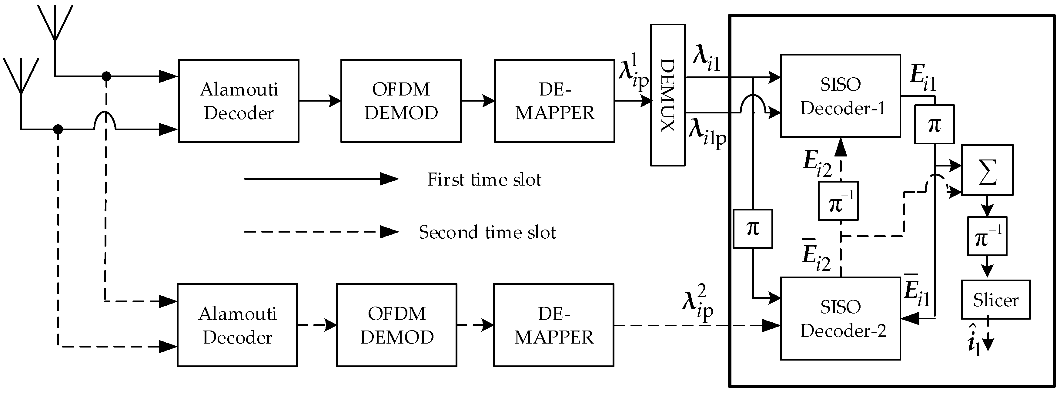
Figure 7.
BER performance of turbo coded OFDM in AWGN channel, L = 256 and four decoding iterations.
Figure 7.
BER performance of turbo coded OFDM in AWGN channel, L = 256 and four decoding iterations.

Figure 8.
BER performance of turbo coded OFDM with MIMO (2 × 2) antennas over Rayleigh fast fading channel, L = 1024 and four decoding iterations.
Figure 8.
BER performance of turbo coded OFDM with MIMO (2 × 2) antennas over Rayleigh fast fading channel, L = 1024 and four decoding iterations.
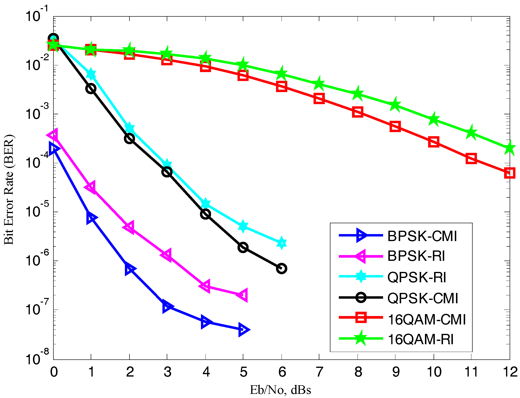
Figure 9.
BER performance of turbo coded OFDM with MIMO (2 × 2) antennas in coded-cooperation and non-cooperation based on CMI, L = 1024, four decoding iterations.
Figure 9.
BER performance of turbo coded OFDM with MIMO (2 × 2) antennas in coded-cooperation and non-cooperation based on CMI, L = 1024, four decoding iterations.
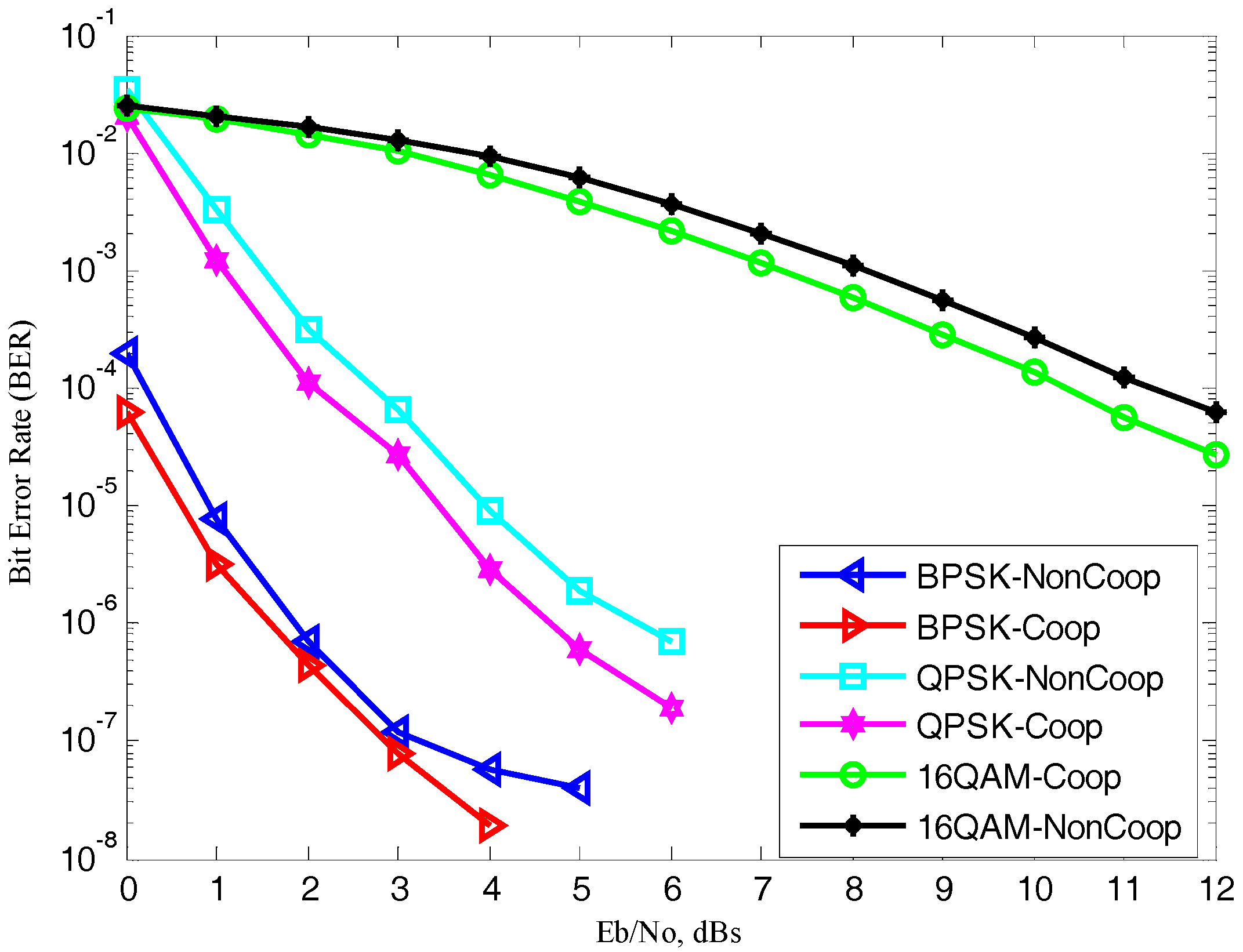
Figure 10.
BER performance of turbo coded OFDM with MIMO (2 × 2) antennas in coded-cooperation under different code rates, based on CMI, L = 1024, four decoding iterations.
Figure 10.
BER performance of turbo coded OFDM with MIMO (2 × 2) antennas in coded-cooperation under different code rates, based on CMI, L = 1024, four decoding iterations.
© 2017 by the authors. Licensee MDPI, Basel, Switzerland. This article is an open access article distributed under the terms and conditions of the Creative Commons Attribution (CC BY) license (http://creativecommons.org/licenses/by/4.0/).
Share and Cite
MDPI and ACS Style
Umar, R.; Yang, F.; Mughal, S. Turbo Coded OFDM Combined with MIMO Antennas Based on Matched Interleaver for Coded-Cooperative Wireless Communication. Information 2017, 8, 63. https://doi.org/10.3390/info8020063
AMA Style
Umar R, Yang F, Mughal S. Turbo Coded OFDM Combined with MIMO Antennas Based on Matched Interleaver for Coded-Cooperative Wireless Communication. Information. 2017; 8(2):63. https://doi.org/10.3390/info8020063
Chicago/Turabian StyleUmar, Rahim, Fengfan Yang, and Shoaib Mughal. 2017. "Turbo Coded OFDM Combined with MIMO Antennas Based on Matched Interleaver for Coded-Cooperative Wireless Communication" Information 8, no. 2: 63. https://doi.org/10.3390/info8020063
Note that from the first issue of 2016, this journal uses article numbers instead of page numbers. See further details here.