Article

Reinforcement Systems for Carbon Concrete Composites Based on Low-Cost Carbon Fibers

Institute of Lightweight Engineering and Polymer Technology, Technische Universität Dresden, Holbeinstraße 3, 01307 Dresden, Germany
*
Author to whom correspondence should be addressed.
Fibers 2018, 6(3), 56; https://doi.org/10.3390/fib6030056
Submission received: 13 July 2018 / Revised: 31 July 2018 / Accepted: 6 August 2018 / Published: 8 August 2018

Abstract

:
Carbon concrete polyacrylonitrile (PAN)/lignin-based carbon fiber (CF) composites are a new promising material class for the building industry. The replacement of the traditional heavy and corroding steel reinforcement by carbon fiber (CF)-based reinforcements offers many significant advantages: a higher protection of environmental resources because of lower CO2 consumption during cement production, a longer lifecycle and thus, much less damage to structural components and a higher degree of design freedom because lightweight solutions can be realized. However, due to cost pressure in civil engineering, completely new process chains are required to manufacture CF-based reinforcement structures for concrete. This article describes the necessary process steps in order to develop CF reinforcement: (1) the production of cost-effective CF using novel carbon fiber lines, and (2) the fabrication of CF rebars with different geometry profiles. It was found that PAN/lignin-based CF is currently the promising material with the most promise to meet future market demands. However, significant research needs to be undertaken in order to improve the properties of lignin-based and PAN/lignin-based CF, respectively. The CF can be manufactured to CF-based rebars using different manufacturing technologies which are developed at a prototype level in this study.

1. Introduction

In civil engineering, in particular, today’s challenges are very clear against the background of the global scarcity of resources and energy [1,2]. For example, approximately 10% of the world’s total energy consumption is needed for the construction and dismantling of buildings. In addition, current buildings only have a limited lifetime of approximately 40 to 80 years. In particular, the estimated 120,000 bridges in Germany with ages of 40 to 50 years present increased safety risks [3,4,5]. The economic damage caused by diversions and traffic jams caused by bridge crossing restrictions alone is currently estimated at 2 billion euros per year in Germany [6]. A lot of these resource and energy problems can be reduced to the use of steel reinforced concrete as the dominant building material of the 20th century [7,8,9,10]. Reinforced concrete is resource-intensive, polluting, heavy, and, above all, susceptible to corrosion. The use of alternative materials like concrete reinforced with carbon fibers offers an enormous potential for saving resources and energy [11,12,13].
So-called carbon concrete composites (C3) are a new material class which is characterized by a rod-like or textile reinforcement made from carbon fibers that are embedded in a special fine-grained concrete matrix. Compared to conventional reinforced concrete, carbon or glass fiber reinforced concrete structures are more durable and resource-saving [14]. Due to their low weight, their outstanding mechanical properties and, in particular, their corrosion resistance, the use of reinforcing materials made of fiber reinforced plastics (FRP) is becoming increasingly important [8,15]. Currently, these materials are mainly used in highly corrosive structures (e.g., bridges), especially in the USA and in Canada [16,17]. Overall, however, the market volume of fiber reinforced concrete is still relatively small. For that reason, there are still no specific legal requirements or standards for the use of this material.
A large number of fiber-based reinforcements of different qualities, designs, and materials are already available on the market [18,19,20,21,22,23,24,25,26,27,28,29,30,31,32,33,34,35]. A distinction has to be made between a flat textile reinforcement manufactured with different textile technologies and a rod-shaped reinforcement mainly produced by pultrusion technology [36,37]. Due to the almost complete automation capability and a continuous feasibility of those two technologies, the processes of reinforcement manufacturing are characterized by very high productivity and correspondingly by low individual part costs. This results in a high application potential with significant added value.
On the one hand, due to the good mass-related mechanical properties of carbon fibers in particular, a significantly lower use of reinforcing material is necessary. On the other hand, unlike steel reinforcement, carbon fiber-based reinforcement is resistant to corrosion, so the reinforcement does not have to be protected from environmental influences. This saves a considerable proportion of concrete cross-section which is not statically necessary but only used for preventing steel to corrode in conventional reinforced concrete structures. Depending on the application, this is, for example, an approximately 30% saving on beam-shaped girders and as much as approximately 40% saving on concrete volume for plate-shaped floor elements. Further to the resource and energy-reducing effects, there are other economic and design advantages. As a result, significantly more filigree load-bearing structures with greater design freedom can be realized due to the smaller possible cross-section dimensions. This allows new architectural fields to be opened up for mass production. In addition, there are also many advantages for construction site production [28]. Due to the considerable reduction in mass, prefabricated parts, for example, can be transported more effectively to the construction site or assembled on the construction site with smaller cranes and with lower energy consumption [9,29,30].
However, the great potential of C³ can only be increased and exploited when the single processes of the C³ manufacturing chain (Figure 1)—from carbon fiber manufacturing to carbon concrete composite production—are fully understood on the one hand and industrialized on the other hand. Established manufacturing processes such as common carbon fiber lines, pultrusion, or modern concrete technology should therefore be preferred.
However, current fiber development is mainly focused on applications in the automotive sector and the aerospace industry. In contrast to the carbon fiber manufacturing process and concrete technology, the manufacturing process of carbon fiber rebars with an adapted geometry profile is not yet industrialized. Besides the manufacturing cost issue, the special requirements for the mechanical and functional properties of carbon fiber reinforced rebars, such as high stiffness or chemical resistance, have not yet been sufficiently met with commercial carbon fibers [36].
Pultrusion technology has become the technology of choice to produce carbon fiber rods with a constant cross-section. Additionally, the first very promising solutions for the adaptation of this technology to manufacture reinforcement for high-strength fine concrete structures already exist [38]. However, the so-called carbon fiber rebar profiling is not yet fully understood and is therefore the subject of ongoing research. To ensure the necessary positive or non-positive bonding effect between the carbon fiber reinforcement structure and the concrete, the rebars must be profiled. This profiling is usually called functionalization in civil engineering. Although there are currently some approaches for profiling continuous fiber reinforced rod structures, the methods available on the market to date still show strong deficits. The current approaches to functionalize fiber based rebars are shown in Figure 2.
One existing profiling approach is based on the constriction of the uncured rod structures using so-called auxiliary elements (e.g., technical yarn) in a continuous production process [37]. These auxiliary elements on one hand are used for shaping and are removed after curing (tight wrapped) and on the other hand are used as the additional reinforcement profile (soft wrapped). An even simpler solution is to sand of the bars for a better connection to the concrete. Due to their shape, the resulting profiles realized by these three approaches have frequently varying fiber volume contents, which has disadvantages from mechanical (e.g., uneven stress efforts under external loads) and production engineering points of view (e.g., hardening cracks due to uneven shrinkage). In addition, there are profiled composite fiber rebars available on the market, based on standard pultrusion rods with a constant cross-section, in which the profile is produced in cured condition by a mechanical finishing step (e.g., milling) [37]. However, this procedure frequently cuts the reinforcing fibers. The tensile strengths of milled rebars are still relatively high. The mechanical performance of those rebars embedded in concrete, however, is relatively bad, especially under cyclic loads, since remaining parts of the milled profiles fail due to shear at lower stress levels. Beyond that, valuable and expensive carbon fiber material is removed during the milling process and ends up unused as garbage. The wear in the milling tools additionally makes this functionalization approach unattractive for use in large series production in the construction industry.
Thus, the two major drawbacks of the current C3 manufacturing technology are addressed in this paper: the need to develop carbon fibers which are tailored to the specifications of civil engineering applications and the efficient manufacturing of functionalized carbon fiber-based rebars. Suitable manufacturing devices are described within that study. The first results for rebar properties are given against benchmark values.

2. Tailored Carbon Fibers

In order to use carbon fibers (CF) and carbon fiber reinforced plastics (CFRP) as reinforcement of concrete, the mechanical properties of steel have to reach a minimum requirement in order to replace it. The minimum stiffness requirements of CFRP-based reinforcement systems can be calculated by a simple rule of mixtures taking typical fiber volume contents either for thermoset matrix systems (typically approximately 60%) or for thermoplastic matrices (typically approximately 45%) into account. The requirements for the stiffness properties of suitable carbon fibers resulting from such a simple calculation results in a CF stiffness of approximately 350 GPa as lower limit for use in a typical thermoset based CFRP reinforcement (with epoxy matrix). The limit according to tensile strength is calculated in a similar way. To reach the required tensile strength value of approximately 500 MPa of reinforcement steel with CRFP, the carbon fibers need to have a tensile strength of approximately 830 MPa for thermoset matrix systems. The required lower limits for the calculated Young’s modulus and tensile strength are shown in Figure 3. Figure 3 summarizes the stiffness and strength properties of commercially available CF based on different raw materials and of research data for stiffness and strength that is published in the literature. It can be stated that the stiffness requirements for CF which result from a direct steel replacement with CFRP defined by the minimum Young’s modulus are already met today by both industrially available and experimental-scientific CF. However, candidate CFs for a concrete reinforcement are either based on polyacrylonitrile (PAN) or on pitch.
Beyond their stiffness and strength characteristics, CFRP reinforcement additionally needs to fulfill other mechanical requirements. In this context, the cyclic material behavior under earthquake loads and the thermo-mechanical behavior in the event of a fire are especially significant. A drawback of the currently available carbon concrete composites is the limited temperature resistance of the CF reinforcements. The present reinforcement applications develop their full performance capacity up to temperatures of approximately 80 °C. Such a temperature resistance is absolutely sufficient for the use of C3 in bridges or as a subsequent strengthening of existing civil engineering constructions. However, in new building constructions, the load case of fire with temperatures of up to 500 °C must be taken into account. For such temperature loads, additional fire protection measures are necessary for C3, which increases the manufacturing costs and thus hinders a broad application of C3. Some publications, like references [40,41,42,43], describe the issue mentioned above. However, there is still a relatively large research need in that field.
Due to the existing high cost pressure in civil engineering, a special focus in the given context additionally has to be set to the manufacturing costs and the availability of the CF. Depending on the production conditions in different countries (e.g., price for raw material, energy costs) and the desired mechanical properties, the production of PAN-based CF causes costs between 10 and 20 €/kg [44,45], whereas high-modulus, pitch-based CF, mostly used for aerospace applications, costs about 70 €/kg [46]. In contrast, the manufacturing cost for reinforcement steel is currently about 0.84 €/kg [47]. Global crude steel production in 2015 was estimated to 1623 million tons. More than half of the capacity was used as structural steel in the building industry, of which 44% was used as reinforcement steel (approximately 357 million tons, see references [48,49]). The production capacity of CF is much lower. The carbon fiber industry specified an annual global theoretical production capacity of 136.5 thousand tons for CF based on PAN and pitch in 2016 [50]. The expected production capacities were not achieved because of lower plant efficiencies, so only 63.5 thousand tons of CF could be produced in 2016 [50]. However, a CF-demand of approximately 160–215 million tons would be needed for a full replacement of reinforcement steel by CF. This CF amount cannot be reached by any means so far. A strong need for low-cost CFs which are specifically tailored to the needs of the building industry on the one hand and a massive increase of CF production capabilities on the other hand is the obvious conclusion based on the simple considerations above.

2.1. CF Based on Polyacrylonitrile (PAN) and Pitch

The production capacities of conventionally produced PAN-CF have so far been limited by the high production times of the sub-process steps, especially oxidative stabilization. Intensive research in the field of plasma-assisted stabilization [51] has shown that the treatment times can be reduced by 75% which leads to an increase in production capacities. Since the existing manufacturing facilities can be easily modified to apply this technology, a short time to market is expected from a process engineering point of view.
Current industrially available CF are produced from copolymers consisting of polymerized acrylonitrile (AN) and various comonomers or carboxylic acids (e.g., methacrylic acid, itaconic acid) which are only produced to a limited extent. AN is conventionally produced in the Sohio process by catalytic oxidation of propene and ammonia under air. Since AN is the raw material for many other products, such as nylon, resins, rubbers, styrene, paints, and cosmetics in addition to CF production, intensive research is currently being conducted into alternative synthesis routes for AN production from biomass. Some routes have already been successfully carried out but are still associated with excessively high costs due to low sales levels [52].
For the production of CF on the basis of AN, AN is first polymerized together with comonomers, dissolved, and spun into precursor fibers. These precursor fibers are then processed to CF in the thermomechanical conversion steps—stabilization and subsequent carbonization under inert gas [53]. Oxidative stabilization and the crosslinking reactions under oxidative atmosphere (air), respectively, are necessary to thermally stabilize the thermoplastic, thermal-degradative polymeric precursor. Three reaction mechanisms—cyclization, dehydrogenation and oxidation—take place in the temperature range from 200 °C to 300 °C to cross-link and form a ladder structure. Introduced comonomers can positively influence the reaction kinetics of the three reaction mechanisms by side reactions catalyzed by the functional groups of the comonomers which can lower the starting temperature of the cyclization mechanisms and thus accelerate the reaction rate. Furthermore, alternative treatment methods, such as plasma treatment or electron beam stabilization, are being tested in order to reduce the duration and energy consumption of the stabilization. The subsequent process step—carbonization—comprises the thermal treatment of the stabilized precursor fibers in a temperature range of 400 °C to 1500 °C under inert gas, at which carbon yields of up to 92% and a Young’s modulus of 400 GPa can be achieved because of the formation of turbostratic carbon phases [54].
A higher Young’s modules of PAN-based CF—up to 750 GPa—can be achieved during graphitization at up to 3000 °C under inert gas, since the turbostratic crystallites are aligned in the longitudinal fiber direction. Alternatively, pitch-based CF exhibit Young’s moduli with maximum values of up to 965 GPa (K1100) (see reference [55]). These reaction mechanisms, either during oxidative stabilization, carbonization or graphitization, can be influenced by process parameters, such as the temperature, heating rate, residential time, and stretching ratio, and further influence the resulting properties, e.g., a high Young’s modulus and stiffness of the CF, which has been investigated in different studies (see, e.g., reference [56]).
The stiffness properties of PAN-based CF significantly exceed those of steel. However, besides the mechanical properties, the manufacturing costs have to be taken into account. To reduce the costs for CF, alternatively synthesized (polypropylene, polyethylene, polyethyleneoxide) and processed bio-based polymers (lignin, cellulose, glucose) are being tested. However, since the properties of the resulting CF are far from reaching those of PAN-based CF without cost-intensive preparation and there are still no process lines for the mass production of bio-based CF, CF will continue to be produced from PAN in the near future.

2.2. CF Based on Lignin Blended Precursor Fibers

The limited availability and the relatively high costs of the high-tech PAN copolymers make the search for alternative precursors, such as lignin, cellulose or nanomodified homopolymers of polyacrylonitrile, highly interesting. Lignin macromolecules are stored in plant cell walls and cause lignification there. Up to 30% of the plant dry matter consists of lignin, making it the world’s most abundant biopolymer after cellulose. With its high concentration of aromatic compounds and a high carbon content of over 60%, lignin is particularly suitable for CF production as an alternative precursor [57]. Due to its availability, lignin also has the potential to reduce possible availability bottlenecks for the building industry. Tt is reported in reference [58] that 147.5 thousand tons of high-purity lignin are available for annual CF-production. Moreover, the global pulp production is estimated to produce 70 million tons of low-purity lignin, of which less than 2% is currently isolated for material use [59] and thus would be available as raw material for carbon fiber production as well. In addition to availability and sustainability aspects, lignin-based CFs offer the possibility of reducing production costs by approximately 50%, as both the costs of the raw material and the energy costs for oxidative stabilization can be reduced [57,60]. However, it has to be considered that lignin has to be conditioned before further processing.
In order to achieve the required properties of the resulting CF, the lignin needs to be purified in further process steps for use as a raw material. However, the mechanical properties of purely lignin-based CF—with a maximum Young’s modulus of 100 GPa and tensile strength of 1000 MPa and below—do not yet meet the aforementioned requirements [61] (see Figure 3). Due to the high molecular inhomogeneity of lignin, the requirements for the use of purely lignin-based CF as concrete reinforcement cannot yet be met because of the formation of defects in the atomic structure and the formation of pores during the thermal treatment of lignin-based precursors, which results in an increase in porosity and thus decreases the mechanical properties [62].
An additional approach to reduce the costs of the raw material is to blend PAN and lignin. By using copolymers, such as aromatic carbons (e.g., naphthalene and anthracene [63] or nitrogen-containing lignin derivatives [64]), lignin-blend-based CFs already reach Young’s moduli of up to 270 GPa (see Figure 3). However, the manufacturing costs of such fibers are most likely higher because of additional process steps. The relationship between the increase in porosity and the reduction in mechanical properties is not linear; rather, it is like a parabolic relationship for lower lignin concentrations and like a hyperbolic curve for more than 15 weight% of lignin [65]. This allows the substitution of a certain proportion of PAN by lignin with fewer defects and subsequently, without significant loss of Young’s modulus. In addition, the reactivity of lignin-PAN-based polymer systems can be increased by the addition of lignin and its functional groups, thus reducing the activation energy for PAN cyclization and oxidation [66]. Thus, the reaction time can be reduced, which reduces the energy consumption of the stabilization and consequently, the production costs. PAN/lignin-based CF can therefore be identified as a promising medium-term option for civil engineering. However, further research efforts for CF based on lignin-blends are needed in order to achieve the mechanical properties at a reasonable cost.
Scientific investigations regarding the manufacturing of lignin-based and PAN/lignin-based CF have mostly been carried out in laboratory tests in a batch process so far. In contrast to such batch processes, a continuous carbon fiber production chain to manufacture tailored carbon fibers was developed within this study as a first step on the way to increasing the manufacturing efficiency and thus decreasing the manufacturing costs (see Figure 4). The CF production chain is located at the Research Center Carbon Fibers Saxony (RCCF) which was founded by the Institute of Lightweight Engineering and Polymer Technology (ILK) and the Institute of Textile Machinery and High Performance Material Technology (ITM).
In a preliminary step, polymer compositions are tested using conventional PAN regenerative resources, such as lignin, and various additives, such as graphene, in order to specifically influence the mechanical properties of the resulting CF. The raw materials are then spun into precursor fibers in a wet spinning plant at the ITM. By varying the process parameters such as the solvent concentration of the spinning solution, the solvent concentration of the coagulation bath, the spinning speed, the turbulence and the distortion of the precursor fiber, the fiber properties, such as the cross-linking and orientation of the polymers as well as the diameter and surface quality of the precursor fiber, can already be influenced [67]. In the next process step, the spun precursor fibers are first oxidatively stabilized in the stabilization line before carbonization in a low-temperature and subsequently, high-temperature furnace. The process parameters are also deliberately varied during these process steps in order to meet special requirements for the properties of the resulting CF. This is achieved through separately adjustable temperature zones in the furnaces, the residence time in the furnaces, and the stretching of the fiber during treatment steps. During the thermochemical conversion from the precursor fiber to the CF, dust particles from the ambient air can lead to inhomogeneities in the atomic structure which can lead to deterioration of the resulting properties. To avoid this influence, the stabilization and carbonization lines are installed in an ISO 8 class clean room. Extensive batch tests made it possible to define the relevant process parameters in advance [62]. Subsequently, the fiber surface is functionalized in the next step by oxifluorination to improve the adhesion between the fiber and the concrete matrix [68]. The mechanical properties (Young’s modulus, tensile strength, etc.) and the morphology of the tailored fibers (porosity, defects on the nanoscale, microscale, mesoscale, and macroscale) are determined either within the RCCF or by partners within the Dresden Concept Network (Dresden Center for Nanoanalytics DCN, Leibniz Institute for Polymer Research (IPF), Fraunhofer IKTS and IWS). The tailored carbon fibers are then manufactured either to textile reinforcement or to rod-like structures (see Section 3).

3. Concepts for CF Rebars

3.1. Design Possibilities

In order to design CF rebars, firstly, their profile of requirements needs to be specified. All types of concrete show high compressive strengths and low tensile strengths at the same time. However, the transfer of tensile and compressive loads is essential in many structures, especially in structures with spanning function, like ceiling elements or bridges. To support concrete in the tensile domain, elements made of materials with high tensile strengths are used. Because the support ideally has to be in the direction of the stress trajectories, the optimum supporting shapes are thin structures with load carrying capability in the axial direction. Fiber reinforced composites are predestinated for the load case.
Optimal and efficient lightweight structures made of fiber reinforced composites or hybrid materials are usually designed in an interactive and not in an iterative way [70]. Thus, the subsequent manufacturing technology has to be considered in the very early design stages because the shape of the reinforcement is strongly affected by the manufacturing technology. Composite materials allow a wide variety of shapes and, in contrast to metallic materials, also adapt the material by varying the orientation of the fibers and the fiber volume content.
Starting from the function of rod-shaped reinforcing structures, firstly, suitable design guidelines were established. The ratio between the contact shell surface and the cross-section has to be as large as possible in order to secure an optimum load transfer and thus a high stress effort in the reinforcing material. Stress peaks at the interface between concrete and reinforcement have to be minimized and the decrease of shear stresses in the reinforcement cross section has to be as low as possible. Furthermore, the contact shell surface has to be profiled for a defined and predictable load transfer according to the reinforcing guidelines.
The realization of the design guidelines mentioned above is possible using different design approaches—starting from the global rod cross section design to cross-section variation up to a local realization of the functionalization (see Figure 5). On Level Zero (design of the cross-section), an optimization starting from a compact full cross-section to closed hollow cross-sections up to open thin-walled or small-sized thin-walled cross-sections can be performed. On Level One (global functionalization), variations of the cross-section may be introduced as well as an axial rotation of the cross-section geometry with the exception of a circular geometry. A Level Two functionalization which is locally realized on the rebar enables a design on the smallest scale. This local functionalization can be realized via bores, indentations, shapings, and radial ribs. Each type of functionalization may be independently implemented and also combined with others. Additionally, further functional elements may be used as inserts or attachments.

3.2. Manufacturing Engineering Solutions

The design possibilities shown above can be realized with different multistep manufacturing technologies. A combination of different technologies is additionally possible (see Figure 5). The functionalized CF rods are produced starting from a primary forming process involving reforming, material joining, and material separation.
The used fiber and matrix materials do not only affect the final properties of the rebars but also the technical realization of the manufacturing process. The developed carbon fibers can be processed with all common composite manufacturing technologies. They therefore have no significant influence on the choice of the manufacturing technology. In contrast, the choice of the matrix material—thermoset or thermoplastic—has a strong impact especially on whether the forming process is suitable. Currently, reinforcing bars with thermoset matrix systems are more common. However, they are not very flexible for subsequent shaping or adjustment in order to use the rebars as an anchoring element or to reinforce curved concrete structures. In that context, thermoplastic based rebars offer a higher degree of design freedom due to their subsequent formability. To secure a high manufacturing efficiency, having a few basic material combinations is beneficial as well as a low number of preferably continuous process steps. The thermoplastic matrix system Polyamide 6 (PA6) combined with different carbon fibers is therefore the focus of this study.
Pultrusion technology was chosen for the manufacture of straight rods with unidirectional continuous reinforcement, since it is the most predestinated and popular technology for such profiles. Novel developments have shown that bent and curved profile geometries can be manufactured in a continuous process [71,72]. Axial surface contouring can be realized in a downstream process step. As mentioned above, such a functionalization is a necessary condition for the use of CF rebars as reinforcement. Surface contouring has already been studied several times, e.g., in references [73,74,75,76]. Glass fibers and thermoset matrices are the primary focuses of these publications.
The basis for pultrusion-based rod manufacturing is the use of pre-impregnated fiber materials. If no commercial pre-impregnated fibers are available, the impregnation may be realized using an upstream injection device. Table 1 summarizes different manufacturing possibilities to realize the design possibilities shown in Figure 5. All manufacturing possibilities were analyzed within that study. The examples shown in Table 1 are subdivided according to the particular manufacturing technologies and their combinations, respectively. For the sake of clarity, only basic technology combinations are shown.

4. Manufacturing Studies for CF Rebars

In closed cooperation with experts from industrial and scientific civil engineering, preferred options for CF rebars were chosen using the classification of the manufacturing concepts shown above. Prototype manufacturing processes based on the developed concepts were tested. In order to further develop those processes to serial processes, only efficient continuous processes were realized. Reference rods without any functionalization were additionally manufactured to evaluate a possible degradation of the axial mechanical properties due to the functionalization step. Those reference rods were partially also used as a preform for the functionalized rods. Five different design-manufacturing-options were chosen for realization: winding-forming with semi-finished tapes, contour-milling, form-pressing, forming with helix pultrusion, and the introduction of additional elements (see Table 2).
For the winding-forming process, a semi-finished carbon fiber reinforced thermoplastic rod-like tape is melted on the surface for optimum adhesion. The molten thermoplastic CF tapes are then spirally placed on the rod. The solidification of the wound functionalization has to take place within the shaping die in order to guarantee a reproducible functionalization shape. The tape has to be pressed against the rod preform to achieve the correct shape of the wounded structure. For that purpose, the shaping die has to have a minimum temperature of 30 K below the melting point of the matrix of 220 °C. An optimization of this process and a determination of the best process parameters were performed using a multitude of manufacturing tests to achieve a stable manufacturing process with reproducible rebar end products.
The contour milling of the functionalization with mostly spiral contour is a commonly used process for fiber reinforced rebars. However, current studies have only focused thermoset rebars. Due to its wide distribution, unilateral milling is also adopted for thermoplastic rebars here. All-round milling manufacturing of the functionalization is realized by a relative rotation between the preform and milling head at room temperature without any cooling of the cutting tool and the rod.
The non-functionalized reference rod is also used as a basis for the functionalization by form-pressing. For that purpose, the reference rod is melted on the surface but not completely molten through. This pre-molten rod is then placed into the warm stamping tool and the outer contour is pressed into the rod. The optimum process parameters with respect to form-pressing quality and duration as well as adhesion to the shaping die have been determined in manufacturing studies. Namely, the rod should be heated on the surface to approximately 10 K above the matrix melting point and the pressing jaws to approximately 50 K below the melting point. By this means, the form-pressing process is finished after five seconds. For a transfer of this process to a continuous manufacturing, the shaping die can be designed as a circumferential press element chain.
The process of thermo-activated pinning [77] of plate-like thermoplastic composite structures has been adapted as another rod functionalization possibility. In this process, a heated metal pin is radially pushed through the rod while the thermoplastic matrix is locally heated. This procedure enables a direct connection of the pin and the rod. An additional load-adapted design can be realized when a link is placed or sprayed on the pin.
The novel technology of helix pultrusion was developed and implemented in order to realize profiled reinforcing rods with an axial undercut. Using relative rotational movement between the entry and exit of the forming element, this novel technology enables defined variable fiber orientation in axial direction of the pultruded rod. The axial undercut functionalization is realized as a thread-like contour. However, this contouring is performed without forcing the fibers into a given form, like in the winding-forming process, which guarantees an optimum load-adapted fiber orientation in the axial direction.
The achievable fiber orientation has a major influence on the mechanical properties of the rebars. Hence, the fiber orientation was determined for all rebar types using typical non-destructive testing (NDT) methods see, e.g., references [78,79] for possible experimental procedures. The rebars (RefNoFuc), (WindForm), and (ContMill) showed a more or less purely axial fiber orientation in the load-bearing cross-section. Local imperfections and thus local axial fiber reorientations were caused by the pressing-in of the contour for the (FormPres) rebar and by the displacement of the fibers during the insertion of the additional elements for the (ThermPin) rebar. Figure 6 shows the evaluation of the fiber orientation in a (HelixPul) CF rebar using computer tomography measurements. The fiber orientation was investigated layer by layer with full CT scans starting from the central axis of the rebar. Within the CT image analysis, cylinders with a defined diameter were placed around the central axis, and the shell surface is shown as girthed area in Figure 6. An axial fiber orientation was proven in the (HelixPul) rebar except for the very edge regions where a fiber undulation was determined, as expected.

5. Experimental Determination of the Mechanical Properties of Functionalized CF Rebars

To evaluate the mechanical properties of the rebar types and the influence of the manufacturing process on the properties, comparative tensile tests were carried out with the rebars. The comparison was made using the determined strengths since strain measurements to determine the Young’s modulus are highly questionable due to the varying outer geometry of the different rebar types. Beyond that, rebars have to be characterized with respect to their tensile strengths according to civil engineering standards [80].
Only the load-bearing cross-section (AS)—the projected continuous cross-sectional area without functionalized areas (AF)—of the specimen geometries was taken into account for the determination of the strengths. Table 3 shows the load bearing cross sections (AS) and the non-applicable part of the functionalization areas (AF) for all rebar types. For the reference rebars without functionalization, the entire cross-section was taken into account for strength determination. Due to the rotationally shifted introduced additional pins in the (ThermPin) configuration, a projected load bearing cross-section could not be determined. Thus, in this configuration, the projected load bearing cross-section was defined as the cross-section in the area of the additional pin.
The basis for the evaluation of the manufacturing process influence on the strengths was a classical material characterization of the virgin composite material. Thermoplastic pre-impregnated tape preforms (SGL-CF-PA6-Tape) made from carbon fibers (SIGRAFIL C T50-4.0/240-T140) and Polyamide 6 were manufactured to plates with unidirectional reinforcement and a fiber volume content (FVC) of 0.45. Standard specimens (dimensions: 250 mm × 20 mm × 1.4 mm) were cut from those plates, and standard tensile tests according to DIN EN ISO 527-4 were performed. Table 4 summarizes the determined relevant parameters.
The functionalized CF rebar prototypes were tested until total tensile failure in the axial direction. A simple clamping device for specimens with cylindrical geometry can be used for a quick material characterization. This device is based on the experience gained in references [81,82] and enables a continuous load introduction into the specimen with minimized stiffness peaks via increasing tightening torques. However, for cross-section geometries that deviate from a circular cross section, a special clamping device to fix the specimens in the testing machine needed to be developed. In particular, for the rods manufactured by helix pultrusion, an inversely segmented cone potting device has proved to be very suitable. This device was designed and manufactured based on the results published in reference [83]. Using increasing cone angles between the single cone segments, even an increasing clamping in the direction of the end of the rod can be realized. Stress peaks and stiffness jumps can be prevented using this modified device. Both clamping systems are shown in Figure 7.
Six specimens were manufactured and tested for every functionalization type. The axial loads at total failure were measured and the strengths were determined using the methodology described above. The determined tensile strengths are shown in Figure 8.
It was found that all tested CF rebars had significantly higher tensile strengths than conventional reinforcing steel rods (B500S with 525 MPa [84]). This strength increase emphasizes the high potential of CF rebars as concrete reinforcement. As expected, the specimens with the smallest deviation from a purely unidirectional fiber orientation showed the smallest strength decrease compared to the reference rebar. However, for a final assessment of the load bearing capacity of all functionalized rods, pull-out tests of the rebar out of a concrete specimen need to be additionally performed. In the case of a purely axial fiber orientation without any further fiber support between the functionalization and the load bearing cross section, the shear strength of the matrix material alone will determine the load bearing capacity in such a pull-out test. It has to be expected that early shear failure without using the full load bearing capacity of the whole cross section will appear in the load introduction area for the winding-forming and the contour milling type rebars. This must lead to a revaluation of the load bearing capacity after a pull-out test series.

6. Conclusions

The novel material carbon concrete composite offers very promising possibilities for civil engineering applications. In order to eliminate the current drawback of the C³ technology on its way to series production:
  • The manufacturing of carbon fibers is tailored to the specifications of the buildingindustry; and
  • The subsequent efficient production of functionalized carbon fiber rods, manufacturing studies was conducted within this study. The study showed the following findings and results:
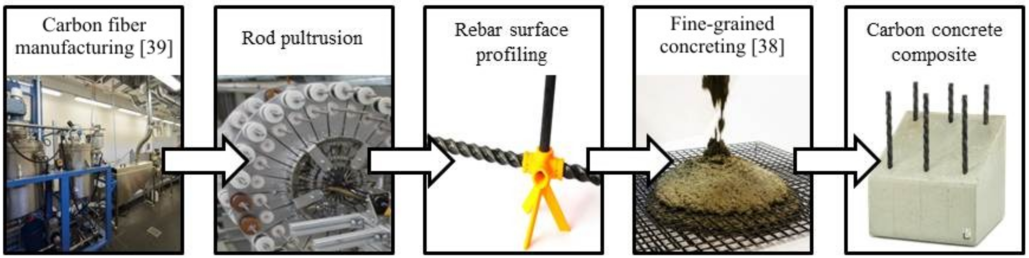
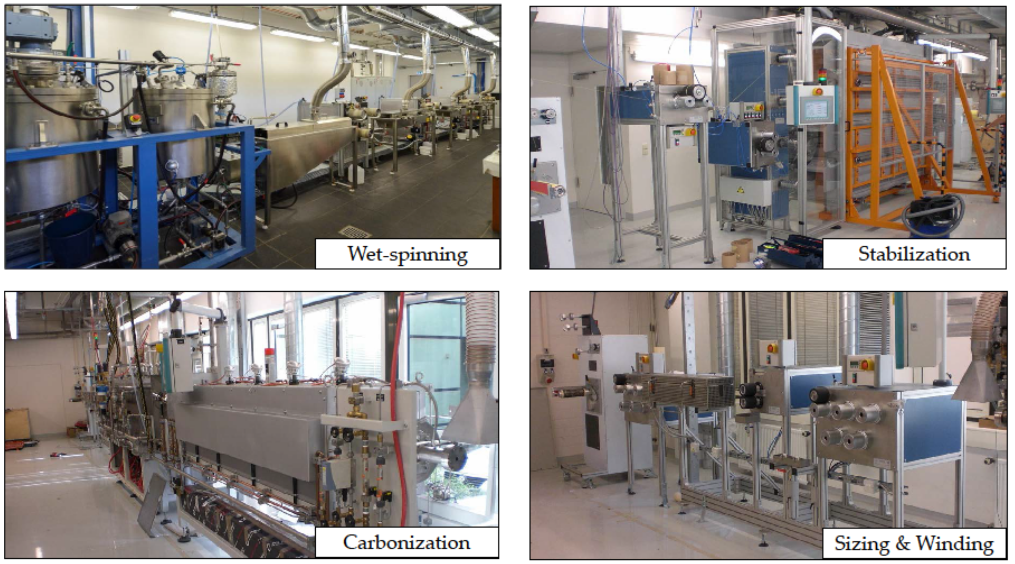
    • A carbon fiber manufacturing line containing precursor development, precursor fiber spinning, stabilization, carbonization, and oxyfluorination was put into operation. This novel process will enable the development of low-cost carbon fibers, either based on lignin or lignin-blend precursor systems. Further tests have to prove that such carbon fibers fulfill all property requirements on the one hand and can be further manufactured to CF rebars at reasonable costs on the other hand.
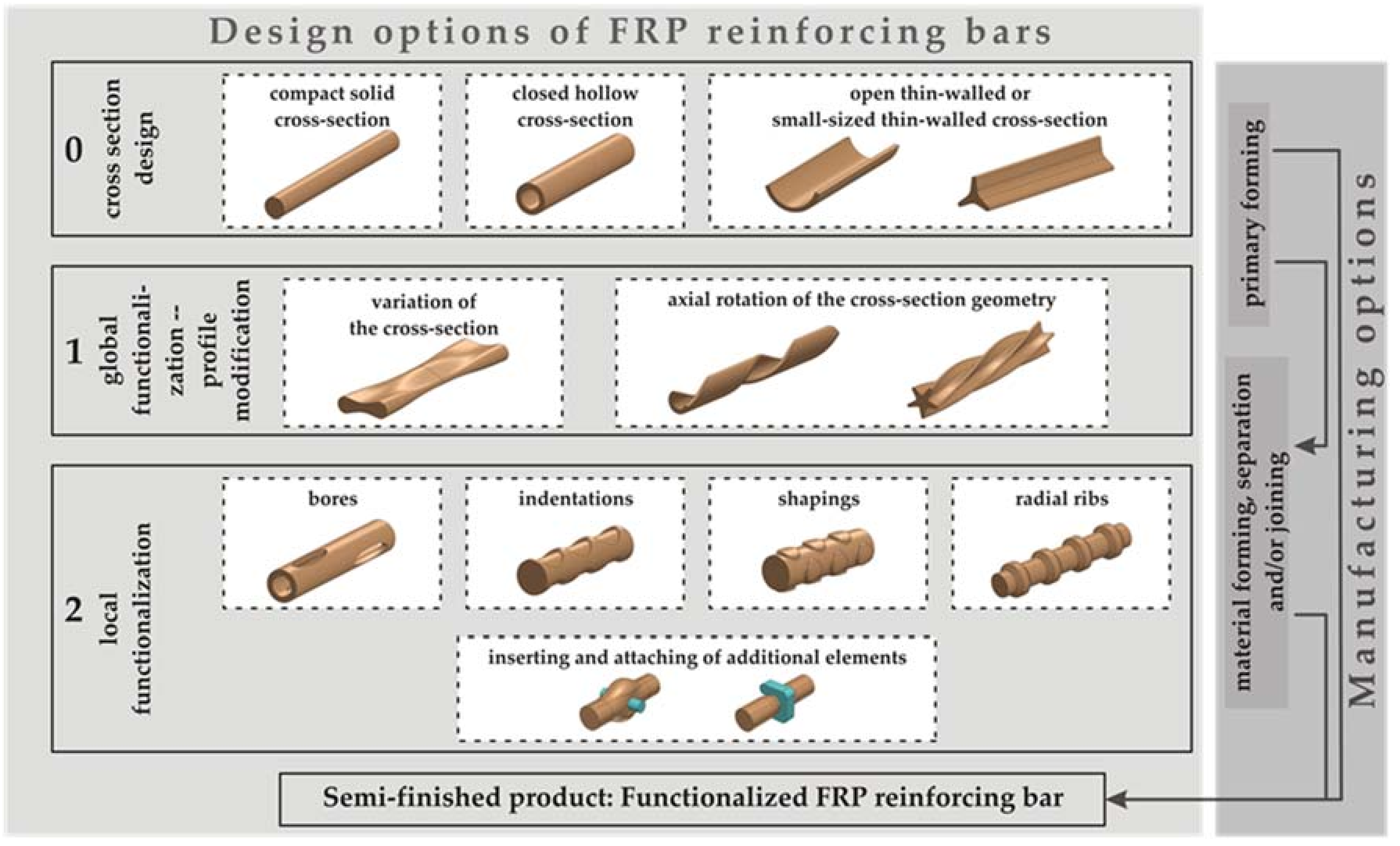
    • A design system for such rebars was developed that contains a multitude of design variants which can be used for further design studies on the component level. The design system also provides an overview of possible subsequent production processes. Thus, a solid basis for a systematic rebar development as a design tool was created.
    • Identified manufacturing processes were developed and implemented on a prototype level in order to realize different rebar variants. They enabled the evaluation of the production process efficiency and formed the basis for the prototypical production of a sufficient number of rebars with a different functionalization.
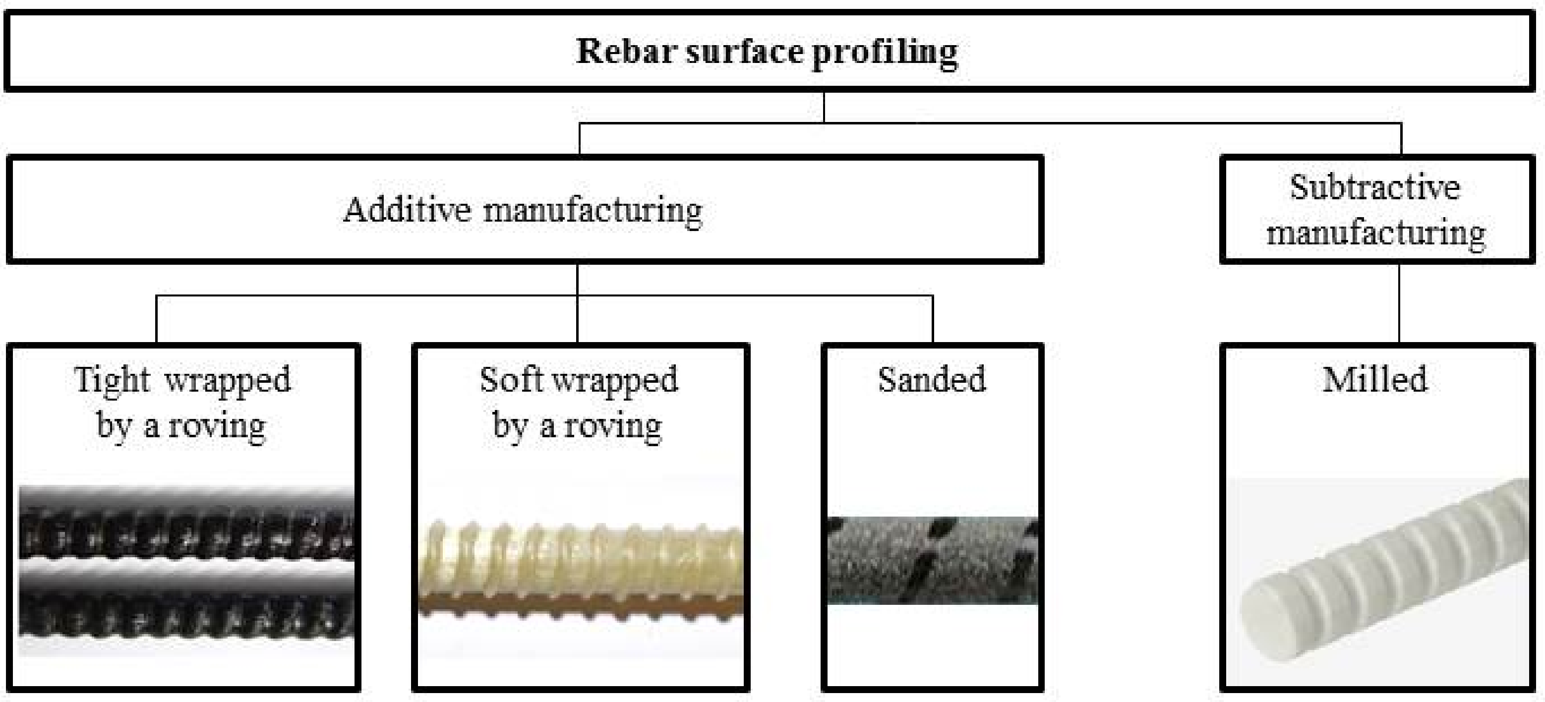
    • Five different manufacturing processes to realize different surface geometry profiles were developed. Especially the so-called helix pultrusion—as a manufacturing process for the production of rebar structures with surface profiling in one single mold step—was identified to be efficient enough to be successfully integrated into an industrialized reinforcement manufacturing process. At the same time, the helix pultrusion process still offers design freedom with regard to surface contours and fiber orientation and thus enables an even greater optimization potential for the reinforcement rod design.
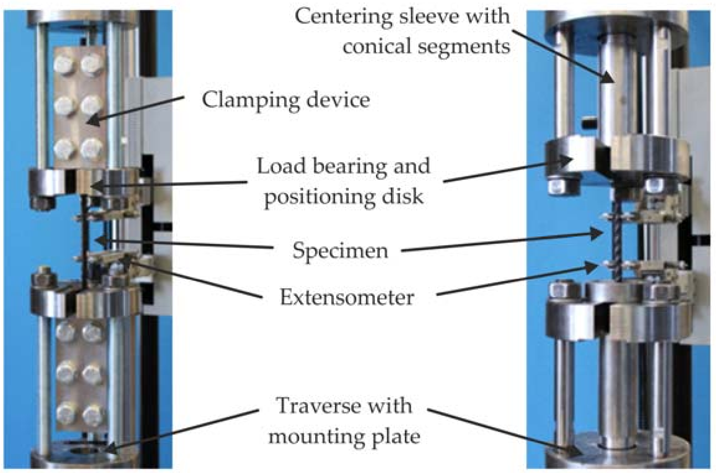
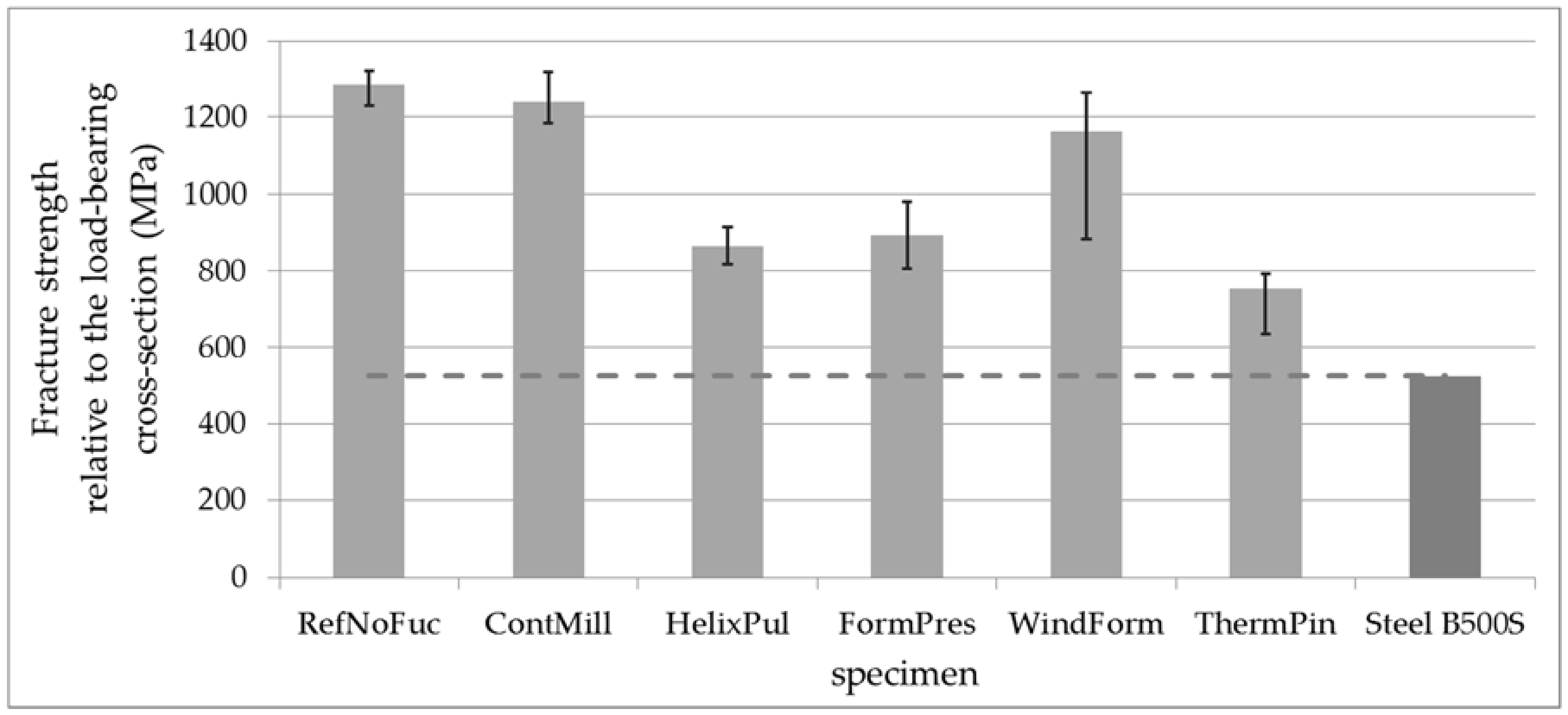
    • The manufactured rebar prototypes were tested with regard to their load-bearing capacity by means of an especially developed novel clamping system. Compared to the characteristic material properties of the basic material which was experimentally characterized with standard specimens, an assessment was made as to how large the material property degradation was due to the manufacturing process. It was found that the properties of all CF-polyamide rebars with different functionalization are high enough for an immediate use as reinforcement since significantly higher strengths than conventional steel rebars were achieved.
    • However, both an optimization of the manufacturing process with respect to the rebar properties and a verifying pull-out test of the rebars out of a concrete matrix may be conducted to finally prove the suitability of the novel production technologies.

Author Contributions

R.B. evaluated the results, wrote and revised the paper. M.T. and D.W. performed the rebar development and wrote Section 3, Section 4 and Section 5. D.S.W. and B.R. performed the carbon fiber development and wrote Section 2. H.J. revised the paper and contributed to the research topic.

Funding

This research was funded by the Federal Ministry of Education and Research (projects B1, V1.1 and V1.2) within the Carbon Concrete Composites (C3) Cluster and by Deutsche Forschungsgemeinschaft (DFG) grant number 397206246.

Acknowledgments

The authors gratefully acknowledge the financial support by funding agencies mentioned above. Beyond that, the authors appreciate the support of the RCCF partners Chokri Cherif, Iris Kruppke, Mirko Richter and Nguyen Hoai An Tran and the DRESDEN concept colleagues Xinliang Feng and Martin Lohe within the carbon fiber development.

Conflicts of Interest

The authors declare no conflict of interests.

References

  1. Kahnt, A.; Schladitz, F.; Tietze, M.; Scheerer, S.; Curbach, M. Carbon concrete—A high-performance material with great efficiency potential. Detail 2016, 4, 302–308. [Google Scholar]
  2. Kahnt, A.; Schladitz, F.; Tietze, M.; Lieboldt, M.; Curbach, M. C3-carbonbeton—Eine materialkombination für die zukunft des bauens artikel. BWI BetonWerk Int. 2016, 6, 22–28. [Google Scholar]
  3. Curbach, M.; Offermann, P.; Hankers, C.H.R. Carbon Concrete Composite: Mit Carbonbeton die Zukunft des Bauens Einleiten. Available online: http://tudalit.de/wp-content/uploads/2016/02/TUDALIT9.pdf (accessed on 24 April 2018).
  4. Lieboldt, M.; Schladitz, F.; Curbach, M. Mit carbon concrete composite C3 neue dimensionen des bauens gestalten. Dresdner Transferbrief 2014, 21, 4–5. [Google Scholar]
  5. Curbach, M.; Scheerer, S. Carbon im brückenbau. In Bauingenieur-VDI-Jahresausgabe 2014/2015; Springer: Düsseldorf, Germany, 2015; pp. 109–118. [Google Scholar]
  6. Ilg, P.; Hoehne, C.H.; Guenther, E. High-performance materials in infrastructure: A review of applied life cycle costing and its drivers—The case of fiber-reinforced composites. J. Clean. Prod. 2015, 112, 926–945. [Google Scholar] [CrossRef]
  7. Scheerer, S.; Schladitz, F.; Curbach, M. Textile reinforced concrete—From the idea to a high performance material. In Proceedings of the FERRO-11 and 3rd ICTRC in Aachen, Aachen, Germany, 7–10 June 2015; Rilem Publications S.A.R.L.: Bagneux, France, 2015. [Google Scholar]
  8. Frenzel, M.; Curbach, M. Designing textile-reinforced structural concrete elements under bending stress—Theoretical basics and practical application. In Proceedings of the 60th BetonTage Ulm, Neu-Ulm, Germany, 23–25 February 2016; BFT International: Neu-Ulm, Germany, 2016; pp. 180–182. [Google Scholar]
  9. Tietze, M.; Schladitz, F.; Kahnt, A.; Curbach, M. Modular building solutions with carbon reinforced concrete. In Proceedings of the IABSE Conference—Bridges and Structures Sustainability—Seeking Intelligent Solutions, Guangzhou, China, 8–11 May 2016; IABSE: Guangzhou, China, 2016. [Google Scholar]
  10. Schladitz, F.; Tietze, M.; Lieboldt, M.; Curbach, M. Carbon and concrete—The future of construction? In Proceedings of the IABSE Conference—Bridges and Structures Sustainability—Seeking Intelligent Solutions, Guangzhou, China, 8–11 May 2016; IABSE: Guangzhou, China, 2016. [Google Scholar]
  11. Tietze, M.; Kahnt, A.; Schladitz, F. Marktpotenzial von Carbonbeton—Prognosen zur Substitution von Stahl Durch Carbon. Available online: http://tudalit.de/wp-content/uploads/2016/02/TUDALIT13.pdf (accessed on 24 April 2018).
  12. Scheerer, S. Was ist textilbeton? Eine kurze einführung in das thema. In Beton-und Stahlbetonbau Spezial; Wiley Online Library: New York, NY, USA, 2015; Volume 110, pp. 4–7. [Google Scholar]
  13. Erhard, E.; Weiland, S.; Lorenz, E.; Schladitz, F.; Beckmann, B.; Curbach, M. Anwendungsbeispiele für textilbetonverstärkung. In Beton-und Stahlbetonbau Spezial; Wiley Online Library: New York, NY, USA, 2015; Volume 110, pp. 74–82. [Google Scholar]
  14. Spelter, A.; Rempel, S.; Will, N.; Hegger, J. Prüfkonzept zur untersuchung des dauerstandsverhaltens von textilbewehrtem beton. Bauingenieur 2017, 92, 364–369. [Google Scholar]
  15. Rempel, S.; Will, N.; Hegger, J.; Beul, P. Filigrane bauwerke aus textilbeton. In Beton-und Stahlbetonbau Spezial; Wiley Online Library: New York, NY, USA, 2015; Volume 110, pp. 83–93. [Google Scholar]
  16. Newhook, J.; Svecova, D. Reinforcing concrete structures with fiber reinforced polymers. In Design Manual No.3, version 2; Isis Canada Corporation: Winnipeg, MB, Canada, 2006. [Google Scholar]
  17. Nanni, A. ACI440.1R-03 Guide for the Design and Construction of Concrete Reinforced with FRP Bars; American Concrete Institute: Farmington Hills, MI, USA, 2003. [Google Scholar]
  18. Aslan, F.R.P.; Hughes Brothers Inc. Rebar Aslan 100 Series Product Data Sheet, Glass Fiber Reinforced Polymer (GFRP). Available online: http://aslanfrp.com/Aslan100/Resources/Aslan100a.pdf (accessed on 1 June 2018).
  19. FiReP Rebar Technology Gmbh. Homepage. Available online: http://de.firepworld.com/products/firep-rebar (accessed on 1 June 2018).
  20. Concrete Protection Products Inc. Homepage. Available online: http://www.fiberglassrebar.com/mat_properties.html (accessed on 1 June 2018).
  21. Schöck Bauteile Gmbh. Technische Information Schöck ComBAR. Available online: http://www.schoeck.de/upload/documents/flashbook/de/combar_/technische_information_schoeck_combar_13-05-10_4442/index.html (accessed on 11 June 2014).
  22. Shanghai Xuyao Fiberglass Reinforcement Products CO., Ltd. Homepage. Available online: http://www.21frp.com/ (accessed on 11 June 2014).
  23. Malnati, P. A hidden revolution: FRP rebar gains strength. Compos. Technol. 2011, 12, 25–29. [Google Scholar]
  24. Composite Rebar Technologies. Homepage. Available online: http://www.hollowrebar.com/Technology/Technology.html (accessed on 1 June 2018).
  25. Dost Kimya Endüstriyel Hammaddeler San. Tic. Ltd. Şti. Homepage. Available online: http://www.dostkimya.com/en/product-browser/dost-rebar-reinforcement/32 (accessed on 11 June 2014).
  26. Pultrall Inc. Homepage. Available online: http://www.pultrall.com/en (accessed on 11 June 2014).
  27. Fortec Stabilization Systems: Datenblatt: Fortec Carbon Bars. Available online: http://www.fortecstabilization.com/datasheets/FortecCarbonBars.pdf (accessed on 11 June 2014).
  28. Rossi, M.; Kirmse, S. Ideas, projects and models for the first building in carbon concrete composite. In Proceedings of the International Design Workshop, Leipzig, Germany, 25–29 September 2017. [Google Scholar]
  29. Schladitz, F.; Ritter, S.; Kahnt, A.; Tietze, M.; Curbach, M.; Lieboldt, M. Herstellung von Fertigteilen aus Textilbeton. Patent DE201510100438, 13 January 2015. [Google Scholar]
  30. Hegger, J.; Geßner, S.T. Bridges with non-metallic reinforcement—International examples. In Proceedings of the 60th BetonTage Ulm, Ulm, Germany, 23–25 February 2016; BFT International: Neu-Ulm, Germany, 2016; pp. 16–18. [Google Scholar]
  31. Monolithic. Available online: http://www.monolithic.org/stories/basalt-fiber-rebar (accessed on 11 June 2014).
  32. Smarter Building Systems. Available online: http://www.smarter-building-systems.com/ (accessed on 11 June 2014).
  33. Sudaglass Fiber Technology Inc. Available online: http://www.sudaglass.com/rods.html (accessed on 11 June 2014).
  34. Vulkan Europe, BV. Available online:. Available online: http://www.vulkan-europe.com/eng (accessed on 11 June 2014).
  35. Solidian Gmbh. Die solidian GmbH und die CG TEC GmbH beschließen kooperation im bereich textiles bauen. Pressemitteilung, 4 July 2014. [Google Scholar]
  36. Böhm, R. Low-cost carbon fibres and novel carbon fibre reinforcement for carbon concrete composites. In Proceedings of the FIBRALSPEC Final Event, Athens, Greece, 29 November 2017. [Google Scholar]
  37. Thieme, M.; Wohlfahrt, D.; Böhm, R.; Gude, M. Design and manufacturing of novel thermoplastic CFRP rods for carbon concrete composites. In Proceedings of the 18th European Conference on Composite Materials, Athens, Greece, 24–28 June 2018. [Google Scholar]
  38. Schneider, K.; Butler, M.; Mechtcherine, V. Carbon concrete composites C³—Nachhaltige bindemittel und betone für die Zukunft. In Beton-und Stahlbetonbau; Wiley Online Library: New York, NY, USA, 2017; p. 112. [Google Scholar]
  39. Cherif, C.; Hund, R.-D. Carbon impact of chemical processing, machinery, equipment and precursor materials on customized fibres. In Proceedings of the 1th International Colloquium on Tailored Carbon Fibres, Dresden, Germany, 3–4 May 2018. [Google Scholar]
  40. Wang, Y.C.; Kodur, V. Variation of strength and stiffness of fibre reinforced polymer reinforcing bars with temperature. Cem. Concr. Compos. 2005, 27, 864–874. [Google Scholar] [CrossRef]
  41. Bisby, L.A.; Williams, B.K.; Kodur, V.K.R.; Green, M.F.; Chowdhury, E.U. Fire performance of FRP systems for infrastructure: A state of the art report. In Research Report 179 of the National Research Council Canada; Conseil National de Recherches Canada: Ottawa, ON, Canada, 2005. [Google Scholar]
  42. Bisby, L.A.; Kodur, V.K.R. Evaluating the fire endurance of concrete slabs reinforced with FRP bars: Considerations for a holistic approach. Compos. Part B 2007, 38, 547–558. [Google Scholar] [CrossRef]
  43. Max, D. Eigenschaften und Abbrandverhalten Vonfaserverbundwerkstoffen, Speziell Kohlefaserverbundwerkstoffen (CFK), Sowie Erforderliche Maßnahmen; Forschungsbericht 177; Karlsruher Institut für Technologie (KIT): Karlsruhe, Germany, 2015. [Google Scholar]
  44. Gil, A.S.; Visotsky, D.; Mears, L.; Summers, J.D. Cost estimation model for PAN based carbon fiber manufacturing process. J. Manuf. Sci. Eng. 2016, 139. [Google Scholar] [CrossRef]
  45. Ellringmann, T.; Wilms, C.H.; Warnecke, M.; Seide, G.; Gries, T.H. Carbon fiber production costing: A modular approach. Text. Res. J. 2015, 86, 178–190. [Google Scholar] [CrossRef]
  46. Shama, R.N.; Simha, T.G.A.; Rao, K.P.; Ravi, K.G.V.V. Carbon Composites Are Becoming Competitive and Cost Effective; Infosys: Bengaluru, India, 2017. [Google Scholar]
  47. Research Concepts Ltd. Homepage. Available online: https://www.stahlpreise.eu (accessed on 19 June 2018).
  48. U. S. Department of Commerce. Global Steel Report. Global Steel Report; International Trade Administration: Washington, DC, USA, 2016.
  49. Steel in Buildings and Infrastructure. Homepage. Available online: https://www.worldsteel.org/steel-by-topic/steel-markets/buildings-and-infrastructure.html (accessed on 19 June 2018).
  50. Sauer, M.; Kühnel, M.; Witten, E. Market Developments, Trends, Outlook and Challenges; Composites market report; AVK: Frankfurt, Germany, September 2017. [Google Scholar]
  51. Kim, S.-Y.; Lee, S.; Park, S.; Mu, J.O.S.; Lee, H.-S.; Joh, H.-I. Continuous and rapid stabilization of polyacrylonitrile fiber nundles assisted by atmospheric pressure plasma for fabricating large-tow. Carbon 2015, 94, 412–416. [Google Scholar] [CrossRef]
  52. Grasselli, R.K.; Trifirò, F. Acrylonitrile from biomass: Still far from being a sustainable process. Top. Catal. 2016, 59, 1651–1658. [Google Scholar] [CrossRef]
  53. Jäger, H.; Cherif, C.H.; Kirsten, M.; Behnisch, T.; Wolz, D.S.; Böhm, R.; Gude, M. Influence of processing parameters on the properties of carbon fibers—An overview. Materialwiss. Werkstofftech. 2016, 47, 1044–1057. [Google Scholar] [CrossRef]
  54. Frank, E.; Steudle, L.M.; Ingildeev, D.; Spörl, J.M.; Buchmeiser, M.R. Carbon fibers: Precursor systems, processing, structure and proberties. Angew. Chem. Int. Ed. 2014, 53, 5262–5298. [Google Scholar] [CrossRef] [PubMed]
  55. Chae, H.G.; Newcomb, B.A.; Gulgunje, P.V.; Liu, Y.; Gupta, K.K.; Kamath, M.G.; Lyons, K.M.; Ghoshal, S.; Pramanik, C.; Giannuzzi, L.; et al. High strength and high modulus carbon fibers. Carbon 2015, 93, 81–87. [Google Scholar] [CrossRef] [Green Version]
  56. Jäger, H.; Behnisch, T.; Wolz, D.; Gude, M.; Böhm, R. Thermal treatment of carbon fibers up to 2700 K and impact on carbon fibers and related polymer composites properties. In Proceedings of the 16th World Textile Conference AUTEX, Ljubljana, Slovenia, 8–10 June 2016. [Google Scholar]
  57. Mainka, H.; Täger, O.; Körner, E.; Hilfert, L.; Busse, S.; Edelmann, F.T.; Herrmann, A.S. Lignin—An alternative precursor for sustainable and cost-effective automotive carbon fiber. J. Mater. Res. Technol. 2015, 4, 283–296. [Google Scholar] [CrossRef]
  58. Milbrandt, A.; Boot, S. Carbon fiber from biomass. In Clean Energy Manufactoring Analysis Center (CEMAC); National Renewable Energy Laboratory: Golden, CO, USA, 2016. [Google Scholar]
  59. Orbis Research. Global lignin products market-segmented by product type, source, application and geography—Trends and forecasts. In Rendering Conscientious Research; Global Information Inc.: Hartford, CT, USA, 2017–2022. [Google Scholar]
  60. Huang, X. Fabrication and properties of carbon fibers. Materials 2009, 2, 2369–2403. [Google Scholar] [CrossRef]
  61. Zhang, M. Carbon Fibers Derived from Dry-Spinning of Modified Lignin Precursors. Ph.D. Thesis, Clemson University, Clemson, SC, USA, 2016. [Google Scholar]
  62. Richter, B.; Wolz, D.S.A.; Böhm, R.; Jäger, H.; Richter, M.; an Tran, N.H.; Cherif, C.; Härtel, P.; Boenke, T.; Dörfler, S.; et al. Thermomechanical conversion during stabilization of Lignin/PAN blended precursor and their effect on porosity. In Proceedings of the World Conference on Carbon, Madrid, Spain, 1–6 July 2018. [Google Scholar]
  63. Ziyu, Z. Process Method for Preparing Intermediate Phase Lignin and Carbon Fibers Thereof. Patent CN103451777A, 18 December 2013. [Google Scholar]
  64. Wohlmann, B.; Stüsgen, S. Schmelzbares Ligninderivat und Daraus Hergestellte Ligninderivatfaser. Patent WO2013144123A1, 3 October 2013. [Google Scholar]
  65. Dong, X.; Lu, C.H.; Zhou, P.; Zhang, S.H.; Wangbc, L.; Li, D. Polyacrylonitrile/lignin sulfonate blend fiber for low-cost carbon fiber. RSC Adv. 2015, 53, 42259–42265. [Google Scholar] [CrossRef]
  66. Liu, H.C.; Chien, A.T.; Newcomb, B.A.; Davijani, A.A.B.; Kumar, S. Stabilization kinetics of gel spun polyacrylonitrile/lignin blend fiber. Carbon 2016, 101, 382–389. [Google Scholar] [CrossRef]
  67. Richter, M.; Hund, R.D.; Cherif, C.; Wolz, D.S.; Böhm, R.; Jäger, H.; Romani Vazquez, A.; Shaygan Nia, A.; Lohe, M.R.; Feng, X. Polyacrylonitrile fibers containing thin-layer graphene particles as precursors for CF. In Proceedings of the World Conference on Carbon, Madrid, Spain, 1–6 July 2018. [Google Scholar]
  68. Kruppke, I. Entwicklung von Methoden zur Realisierung von Maßgeschneiderten Adhäsionseigenschaften von Faserbasierten Hochleistungswerkstoffen für Composites. Ph.D. Thesis, TU Dresden, Dresden, Germany, 2018. [Google Scholar]
  69. Gude, M. Carbon fibre research in Dresden. In Proceedings of the 1st International Colloquium on Tailored Carbon Fibres, Dresden, Germany, 3–4 May 2018. [Google Scholar]
  70. Hufenbach, W.; Helms, O. Konstruieren von strukturbauteilen aus faser–kunststoff–verbunden. In Pahl/Beitz Konstruktionslehre–Methoden und Anwendung Erfolgreicher Produktentwicklung, 8th ed.; Feldhusen, J., Grote, K.-H., Eds.; Springer: Berlin, Germany, 2013; pp. 648–664. [Google Scholar]
  71. Jansen, K. Machines for radius, curves and frames. In Proceedings of the 13th World Pultrusion Conference, Prague, Czech Republic, 3–4 March 2016. [Google Scholar]
  72. Christmann, B. Gekrümmte bauteile für den leichtbau. MM–Maschinenmarkt. Ind. Mag. 2016, 47, 64–65. [Google Scholar]
  73. Henke, M.; Fischer, O. Formoptimierte filigrane stäbe aus UHPC und korrosionsfreier CFK-bewehrung für variable räumliche stabtragwerke. In Leicht Bauen mit Beton: Forschung im Schwerpunktprogramm 1542, Förderphase 1; DFG: Bonn, Germany, 2014; pp. 48–59. [Google Scholar]
  74. Achillides, Z. Bond Behaviour of FRP Bars in Concrete. Ph.D. Thesis, Centre of Cement and Concrete, Department of Civil and Structural Engineering, The University of Sheffield, Sheffield, UK, 1998. [Google Scholar]
  75. Malvar, L.J. Tensile and bond properties of GFRP reinforcing bars. ACI Mater. J. 1995, 92, 276–285. [Google Scholar]
  76. Niewels, J. Zum Tragverhalten von Betonbauteilen mit Faserverbundkunststoff-Bewehrung. Ph.D. Thesis, Fakultät für Bauingenieurwesen, Rheinisch-Westfälischen Technischen Hochschule Aachen, Aachen, Germany, 2008. [Google Scholar]
  77. Hufenbach, W.; Böhm, H.; Kupfer, R.; Pohl, M.; Hornig, A. Thermoactivated pinning—An innovative technology for the joining of fibre-reinforced thermoplastic composites. In Joining Plastics—Fügen von Kunststoffen; DVS Media: Eltville, Germany, 2014; Volume 8, pp. 184–189. [Google Scholar]
  78. Bohm, R.; Stiller, J.; Behnisch, T.; Zscheyge, M.; Radloff, S.; Gude, M.; Hufenbach, W. A quantitative comparison of the capabilities of in situ computed tomography and conventional computed tomography for damage analysis of composites. Compos. Sci. Technol. 2015, 110, 62–68. [Google Scholar]
  79. Hufenbach, W.; Richter, H.; Langkamp, A.; Bohm, R. Application of acoustic emission analysis for damage investigations in fibre and textile reinforced composites. In Proceedings of the 1st Conference on Damage in Composite Materials, Stuttgart, Germany, 18–19 September 2006; NDT.net: Bad Breisig, Germany, December 2006; Volume 11. No. 12. [Google Scholar]
  80. Betonstahl—Teil 3: Betonstabstahl, Prüfungen, DIN 488-3:1984-09. Available online: http://www.rosmetiz.ru/upload/files/gosts/din%20488-2.pdf (accessed on 9 May 2018).
  81. Schmidt, J.W.; Bennitz, A.; Täljsten, B.; Pedersen, H. Development of mechanical anchorage for CFRP tendons using integrated sleeve. J. Compos. Constr. 2010, 14, 397–405. [Google Scholar] [CrossRef]
  82. Ye, Y.; Guo, Z. Experimental investigation on the anchorage performance of clamping anchors for carbon fiber reinforced polymer rods. Adv. Sci. Lett. 2011, 4, 922–926. [Google Scholar] [CrossRef]
  83. Horvatits, J. Vergussverankerung für spannglieder mit kohlenstofffaserverbundwerkstoff, dissertation. In Fakultät für Bauingenieurwesen; Technische Universität Wien: Vienna, Austria, 2008. [Google Scholar]
  84. Betonstahl—Teil 1: Stahlsorten, Eigenschaften, Kennzeichnung, DIN 488-1:2009-08. Available online: http://www.rosmetiz.ru/upload/files/gosts/din%20488-2.pdf (accessed on 9 May 2018).
Figure 1. Process chain for the manufacturing of carbon concrete composites (reproduced with permission from [38,39]).
Fibers 06 00056 g001
Figure 2. State-of-the-art approaches for rebar functionalization (rebar profiling).
Fibers 06 00056 g002
Figure 3. Tensile strength vs. Young’s modulus of different carbon fibers.
Fibers 06 00056 g003
Figure 4. Novel Research Center Carbon Fibers Saxony (RCCF) carbon fiber process chain for tailored carbon fibers [69].
Fibers 06 00056 g004
Figure 5. Design and manufacturing options for CF rebars with different geometry profiles.
Fibers 06 00056 g005
Figure 6. CT-based measurement of the fiber orientation in CF rebars produced by helix pultrusion.
Fibers 06 00056 g006
Figure 7. Specimen clamping—inversely segmented cone potting clamping (left), clamping plate fixation (right).
Fibers 06 00056 g007
Figure 8. Comparison of the load bearing capacity of the functionalized CF rods compared to the non-functionalized reference rod and conventional steel rebars.
Fibers 06 00056 g008
Table 1. Manufacturing scheme for different functionalization possibilities of CF rods.
Primary forming and separating processing Fibers 06 00056 i001
Contour milling
Fibers 06 00056 i002
Drilling
Primary forming and reforming processing Fibers 06 00056 i003
Form-pressing
Fibers 06 00056 i004
Out-displacing and penetrating
Primary forming and material joining Fibers 06 00056 i005
Injection forming
Fibers 06 00056 i006
Winding, braiding
Primary forming as the only process step Fibers 06 00056 i007
In-situ rolling
Fibers 06 00056 i008
Thread forming, helix pultrusion
Table 2. Overview of realized manufacturing technologies and functionalization.
FunctionalizationManufacturingFunctionalized CF Rod
Reference
(no Functionalization)
(RefNoFuc)
Fibers 06 00056 i009 Fibers 06 00056 i010
Winding-forming by means of semi-finished tape
(WindForm)
Fibers 06 00056 i011 Fibers 06 00056 i012
Contour milling of functionalization
(ContMill)
Fibers 06 00056 i013 Fibers 06 00056 i014
Form-pressing of functionalization
(FormPres)
Fibers 06 00056 i015 Fibers 06 00056 i016
Primary forming only with helix pultrusion
(HelixPul)
Fibers 06 00056 i017 Fibers 06 00056 i018
Out-displacing and penetrating of cylindrical elements
(ThermPin)
Fibers 06 00056 i019 Fibers 06 00056 i020
Table 3. Load-bearing cross-sections of the individual rebar variants.
(RefNoFuc)(ContMill)(HelixPul)(FormPres)(WindForm)(ThermPin)
Fibers 06 00056 i021 Fibers 06 00056 i022 Fibers 06 00056 i023 Fibers 06 00056 i024 Fibers 06 00056 i025 Fibers 06 00056 i026
AS = 50.3 mm2AS = 32.2 mm2AS = 41.9 mm2AS = 41.3 mm2AS = 50.3 mm2AS = 34.6 mm2
-AF = 19.1 mm2AF = 26.1 mm2AF = 8.9 mm2AF = 19.1 mm2AF = 92.1 mm2
Table 4. Determined mechanical properties of the basic material (SGL-CF-PA6-Tape with fiber volume content 0.45).
Mechanical PropertySGL-CF-PA6-Tape (FVC 0.45)
Young’s modulus, E1 (GPa)101.6
Tensile strength, R1 (MPa)1290
Fracture strain, A1 (%)1.1

