A Magnetic Microrobot with in situ Force Sensing Capabilities


School of Mechanical Engineering, Purdue University, 585 Pudue Mall, West Lafayette, IN 47907, USA
*
Author to whom correspondence should be addressed.
Robotics 2014, 3(2), 106-119; https://doi.org/10.3390/robotics3020106
Submission received: 13 January 2014
/
Revised: 23 March 2014
/
Accepted: 27 March 2014
/
Published: 8 April 2014
(This article belongs to the Special Issue The Frontiers of Micro and Nanorobotic Systems)
Abstract
:This paper presents a proof-of-concept prototype of a micro force sensing mobile microrobot. The design consists of a planar, elastic mechanism serving as computer vision-based force sensor module, while the microrobot body is made from a magnetic layer driven by a magnetic field. From observing the deformation of the elastic mechanism, manipulation forces can be determined. The deformation is tracked by a CCD camera attached to an optical microscope. This design is validated through experimental tests with a micromachined prototype. The preliminary results verify this first microrobot prototype is indeed capable of in situ force sensing. This concept can be scaled down further for next generation designs and can be designed for real biomedical applications on microscale.
1. Introduction
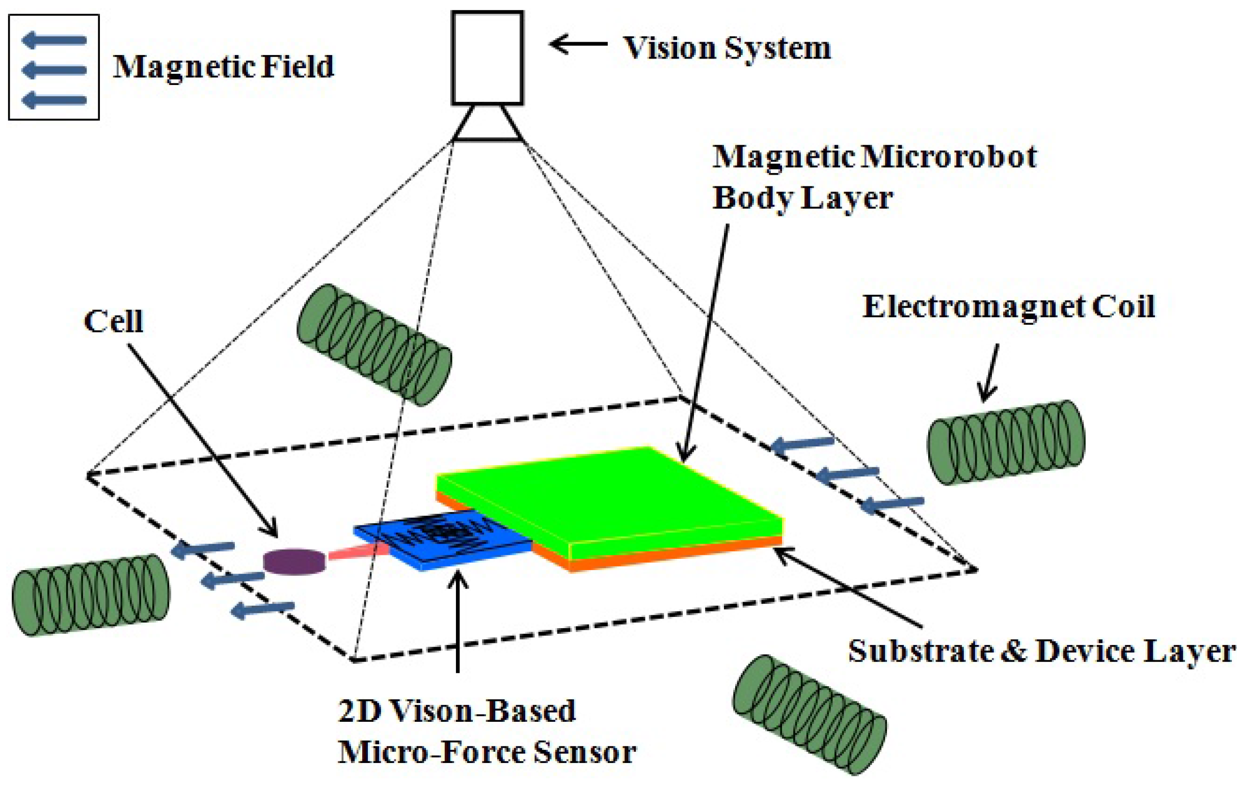
Untethered mobile robots on microscale have emerged as one of the new frontiers in intelligent automation systems only since the last decade. They have shown potential in biomedical applications, such as in biological processes at cellular level and in vivo medical tasks. The microscale robot agents provide attractive working modes due to their small size [1]. At the same time, the limited footprint also makes it challenging to carry function modules on board, such as the power for actuation and in situ sensing. However, the real advantages of microrobot system can only be utilized if it possesses high resolution sensing functions [2]. Therefore, it is desired to incorporate force sensing functionality into a microscale robotic system for biomedical applications. Additionally, micro-force interactions on real biomedical single cell manipulations are still underexplored. When manipulating biological cells, the typical forces ranges are at the micro-Newton (μN) level or lower. Therefore, the goal of our work in this paper is to come up with a wireless mobile micro device that incorporates a micro force sensing module on board (Figure 1), which is able to send force feedback information in situ.
Figure 1.
The concept system of the micro-Force Sensing Mobile Microrobot (μFSMM). The vision-based micro force sensor end-effector is connected with a magnetic base. The base is driven by a series of electromagnetic coils. Deformation of vision-based force sensor is observed with the vision system.

2. Related Work
For wireless mobile microrobots, actuation itself is challenging due to the constraint space for power storage. Electrical [3] and thermal [4] energy have been applied to power microrobots, which are based electrostatic attraction and laser heating, respectively. These designs require an engineered working surface that is not always available in practical biomedical applications. Thereafter, magnetic actuation has routinely been applied in microrobotic systems.
There are various magnetic microrobot systems that have been developed successfully. In fluid media, a micro spiral magnetic structure can swirl forward with a rotating magnetic field [5]. On the dry surface, devices made of asymmetric magnetic hammers, named “MagMite" [6] and “PolyMite" [7], are able to translate with an oscillating magnetic field. The micro agent made of pure neodymium-iron-boron magnetic block [8] can translate in a rocking (stick-slip) mode with pulsing magnetic field signals. The ball shape [9] and rod shape (“RodBot") [10] prototypes have also been fabricated to roll on surfaces. Tumbling locomotion has also been realized through a microscale magnetic microrobot [11,12]. Driving the magnetic microrobot directly by magnetic field gradients has also been conducted successfully [13,14]. The magnetic assembly named “OctoMag" has been manipulated in five dimensions of freedom. On the smaller scale, Martel et al. [15] have used an MRI scanner to actuate a hydrogel-based shrinkable micro agent mixed with magnetic particles.
Various micro force sensors based on microelectromechanical systems (MEMS) have been developed to derive information used for cellular force measurements [16]. Indirect force measurement methods have been applied such as piezoresistive principle [17,18], strain gauge [19,20] and capacitance-based force measurement [21,22]. In [17], the micro force is sensed by the silicon cantilever beam deposited with resistors based on the piezoresistive effect. In [19], an orthotweezers system has been developed for automated microassembly. Beyeler et al. [22] have developed six-axis force-torque sensor consisting of microfabricated comb capacitors with micro-Newton (μN) and nano-Newton-meter (nN · m) resolution. Koch et al. [23] have fabricated and tested a compliant surface-micromachined spring which is able to measure forces as small as 1 pico-Newton (pN). The common feature of these devices are complicated structures and fabrication process. They are also usually not compatible with working in fluidic environments. Moreover, the auxiliary drive electronics will clutter the workspace, when being used for microscale biomedical applications. However, a vision based force sensor is suitable for the applications in limited workspace. A vision based computational force sensor for elastically deformable objects is presented in [24]. Greminger et al. [25] present a method to visually measure the force distribution the contour data in the image of linearly elastic object. On the microscale, optics are used to sense contact forces in [26,27]. For single cell study, polydimethylsiloxane (PDMS) microbeams have been used to sense one dimensional micro-scale forces [28,29].
This paper presents the micro-Force Sensing Mobile Microrobot (μFSMM, Figure 1), which couples a two-dimensional (2D) vision based micro force sensor with a magnetic mobile microrobot. This wireless micro agent owns mobility and in situ force sensing function at the same time, that is preferable to the biomedical applications on microscale. It is the first truly microscale mobile robot with onboard sensing capabilities. The design, modeling, prototyping, preliminary calibration and testing of this first μFSMM are presented accordingly.
3. Micro-Force Sensing Mobile Microrobot (μFSMM) Design
The target application for the μFSMM is force controlled biological cell manipulation (Figure 1). Therefore, a 2D elastic end-effector mounting on a magnetic microrobot body is desirable. The end-effector, that serves as the vision based micro force sensor, is based on our previous work in [30]. The tip of the end-effector is designed with a point contact in an effort to reduce surface contact, and therefore stiction, with the cell being manipulated. Furthermore, the micro force sensor needs to have a resolution which ranges from μN down to nN level for this application. Therefore, the vision based micro force sensor has a maximum threshold of stiffness, corresponding to the vision system being utilized.
3.1. Design Specifications
In order to meet the function requirements, the design parameters are evaluated by the constraints imposed by our present vision system and electromagnetic microrobot testbed. The observing vision system consists of a CCD camera (FL3-FW-14S3C, www.ptgrey.com) and zoom imaging lens (VZM 330i, www.edmundoptics.com). The imaging parameters are summarized in Table 1. Therefore, assuming a pixel tracking accuracy of ±1 for the sensor deformation, the micro force sensor needs to deflect more than Δmin ≈ 4 μm at maximum magnification or 15 μm at minimum magnification. (Note that the accuracy of vision based sensing not only relies on the image resolution, but also on the robustness and accuracy of the feature tracking algorithm utilized.)

| Camera sensor size (mm) | 7.60 (H) × 6.20 (V) |
| Pixels | 1, 360 (H) × 1, 024 (V) |
| Primary magnification (PMAG) | 0.75 X − 3 X |
| Field of view (FOV, mm) | 10.13 (H) × 8.27 (V) at 0.75 X |
| 2.53 (H) × 2.07 (V) at 3 X | |
| Measurement accuracy (μm) | 14.9 (H) × 16.2 (V) at 0.75 X |
| 3.7 (H) × 4.0 (V) at 3 X |
Note: (1) H and V stands for horizontal and vertical directions of imaging view, respectively. (2) The pixel error is assumed as ±1 for a high contrast image.
As the first generation of this μFSMM prototype design, the agent is designed at a large scale for easy prototyping, but the feature sizes are still at the microscale with the total footprint no larger than the smallest field of view (FOV, 2.53 mm × 2.07 mm) of vision system. Thereafter, the magnetic microrobot has an area of 1.5 mm × 1.0 mm for evaluation of its magnetic force exerting capabilities. The first generation agent magnetic base is prototyped with nickel foil whose thickness is about 25 μm. The electromagnetic coil testbed [11] utilized is able to produce a magnetic field with flux intensity (B) greater than 50 mT within the workspace and a field gradient (∇B) greater than 1.5 T · m−1. Thus, the typical magnetic force Fm is evaluated at 50% power as:
where Vm is the magnetic volume and M is the magnetization of the nickel body. Thereafter, the required maximum stiffness Kmax of the proposed 2D elastic micro force sensor corresponds to the condition where this magnetic force value Fm results in the minimum deflection Δmin = 4 μm detected by the vision system. That is calculated based on:
where the acting force F = Fm, the deflection of the micro force sensor Δ = Δmin = 4 μm. Therefore, the maximum stiffness Kmax equals to 0.014 N/m.
3.2. Micro Force Sensor Design
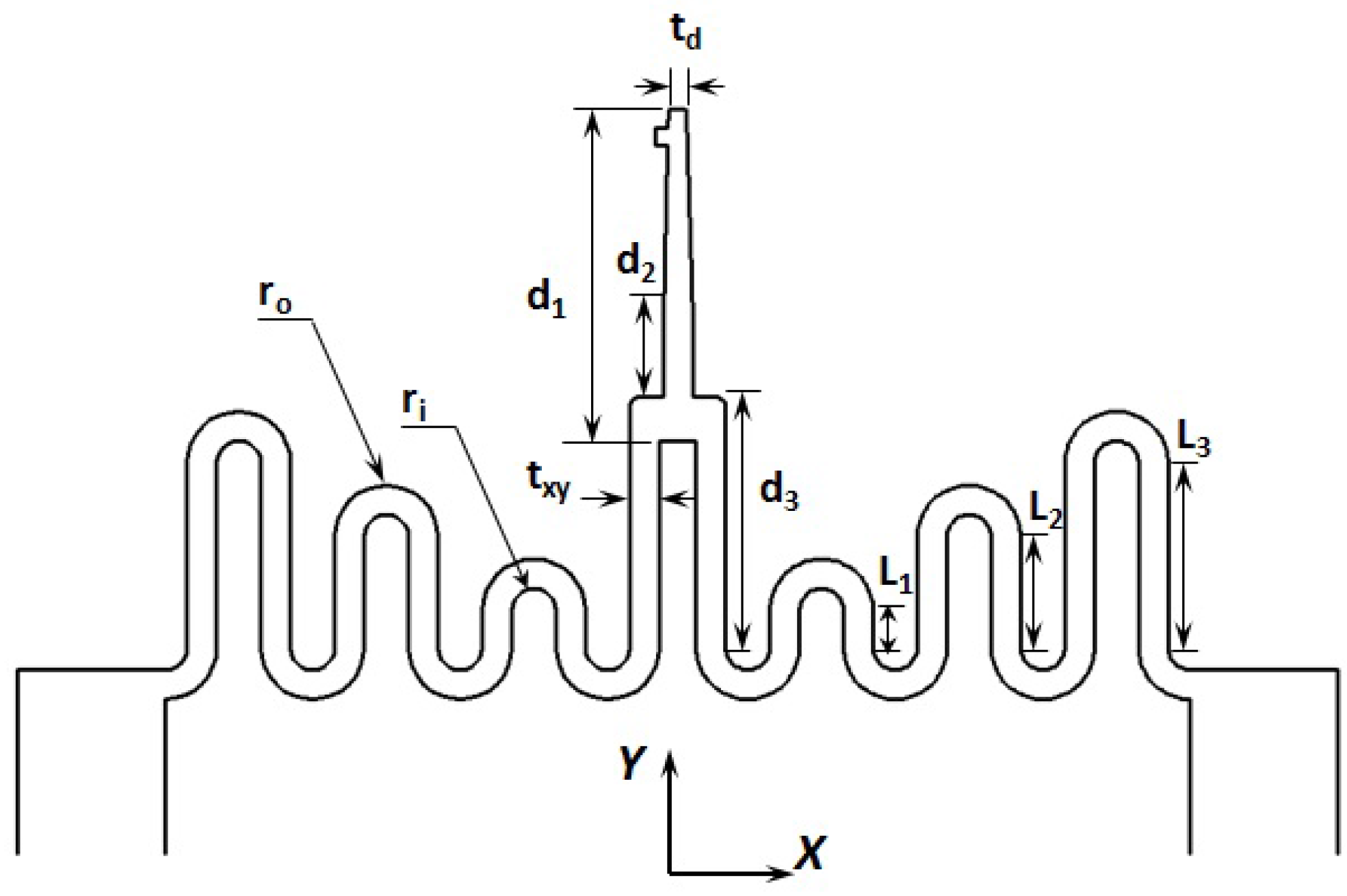
The micro force sensor end-effector is essentially a two-dimensional low stiffness spring [30]. The general topology for the design is shown in Figure 2. The suspended structure of multiple spring beam geometries are designed for low stiffness in both lateral (X) and transverse (Y) directions. The geometric parameters of fourteen candidate designs (P1 − P14) in [30] range as following: n : 1 − 4; L1 = 30 − 300 μm; L2 = 125 − 250 μm; L3 = 125 − 250 μm; L4 = 125 − 250 μm; d1 = 250 − 450 μm; d2 = 50 − 100 μm; d3 = 200 − 590 μm, where n is the number of springs on each symmetric side relative to Y axis.
Figure 2.
Diagram of the micro force sensor end-effector of the μFSMM. The probe length and spring length are variable for tuning the device stiffness [30].
Figure 2.
Diagram of the micro force sensor end-effector of the μFSMM. The probe length and spring length are variable for tuning the device stiffness [30].

The material of the micro force sensor is selected as polydimethylsiloxane (PDMS) due to its small Young’s modulus, as low as hundreds of KPa. In addition, PDMS is compatible with biological applications [31]. After the geometry is chosen, the stiffness of each design is numerically evaluated through finite element analysis (FEA) models in COMSOL software (www.comsol.com). Design candidates that meet the stiffness design requirement (K ≤ 0.014 N/m) for the μFSMM system are selected for further investigation.
3.3. Mobile Microrobot Design
In fluidic environments, the mobile agent needs to overcome the resistance which is generated by pressure gradients and friction drag on the object surface. When the agent is small compared to the environment, the pressure gradient can be treated as zero and the fluid drag Fd only depends on the friction on the agent surfaces due to the motion in fluid. Therefore, the requirement of mobility for the μFSMM can be expressed as:
where Fm is the magnetic driving force evaluated as Equation (1). Considering the μFSMM as a 2D flat plate, the fluid drag force Fd can be evaluated through the drag coefficient Cd as [32]:
where ρ is mass density of the fluid media, v is flow velocity, S is the total surface area in contact with the fluid and Re is the Reynolds number as Re = vL/v. ν is the kinematic viscosity of the fluid media and L can be treated as the length of the microrobot. Equation (4) is valid only if the microrobot is translating in a laminar flow. Due to the small inertia, the microscale robot has a low Reynolds number, which indicates the laminar flow domain. Thereafter, the mobility requirement for the μFSMM agent can be assessed as:
where the acting magnetic force can be evaluated in Equation (1). For quantitative estimation, assume the magnetic volume is Lm × Lm × tm, the dimension to the total device is L × L × t and t/L = 1/10, Lm/L = 2/3, where L is the length and t is the thickness. In addition, assume the microrobot works in water environment, where ρ = 1 × 10³ kg/m3, ν = 1.0 cSt = 1 × 10⁻⁶ m2/s, and the set translation velocity is αL, which means the microrobot travels α times of body length per second. Let α = 2 and plug Equation (1) and Re into Equation (5), we can evaluate the required thickness of magnetic layer as:
which means in the above working environment, the minimum thickness of the nickel magnetic layer for a 1 mm device is about 7 μm. Equation (6) indicates that this requirement is related to the fluid properties, the available magnetic field, the desired mobility and the body length of the μFSMM microrobot.
4. Prototype Fabrication
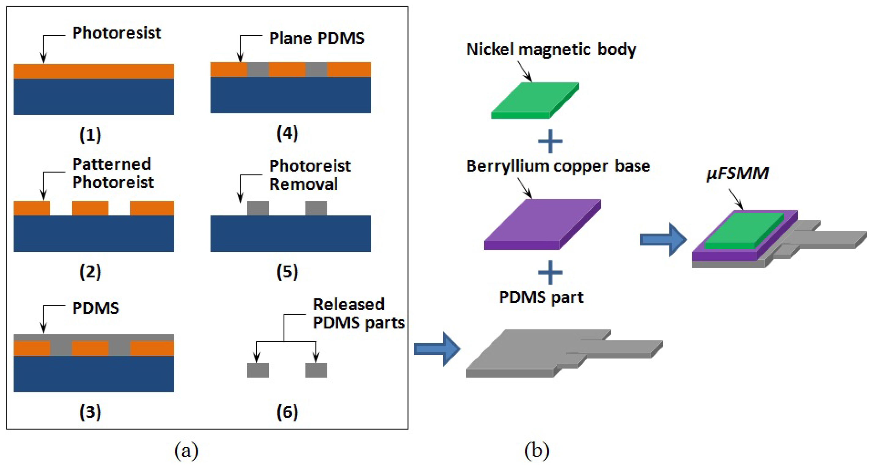
The μFSMM prototype is fabricated through multiple step surface micromachining process and subsequent assembly (Figure 3). As shown in Figure 3a, in order to manufacture the PDMS micro force sensor, a mold made of negative photoresist (KMPR 1050, MicroChem, www.microchem.com) is patterned at first in step (1) and (2). The thickness of the mold is customized in the spin coat process in step (1), which determines the resultant thickness of the micro force sensor. For easy releasing of the force sensor part, the patterned photoresist mold is then exposed to CF4 plasma for 1 min. PDMS (Sylgard 184, www.dowcorning.com) mixed with base:cure ratio of 12.5:1 (by mass) is then filled in the mold by a spin coating process (step (3)). After curing, the overflowed PDMS layer is planed down (step (4)) either by dry etching with CO2 laser or wet etching with a solution of tetrabutylammonium fluoride (TBAF) in N-methylpyrrolidinone (NMP) (3:1; v/v; NMP/75% TBAF in water). Discussion of these two techniques are presented in [30]. Afterwards, the photoresist mold is dissolved in Remover PG bath (step (5)) and the PDMS part is released in step (6).
After the individual PDMS part is released, a beryllium copper base is epoxied to the base section of the PDMS force sensor. The base layer is used to strengthen the device and helps the attachment with magnetic body layer. The overall body length of the fabricated prototype is around 2.5 mm. Based on Equation (6), the required thickness of the magnetic layer is about 16 μm. Therefore, a customized 25 μm thick nickel foil (www.alfa.com) is attached to the previous subassembly. This nickel layer serves as the magnetic microrobot body, which makes it possible to drive the whole assembly by the magnetic field gradients.
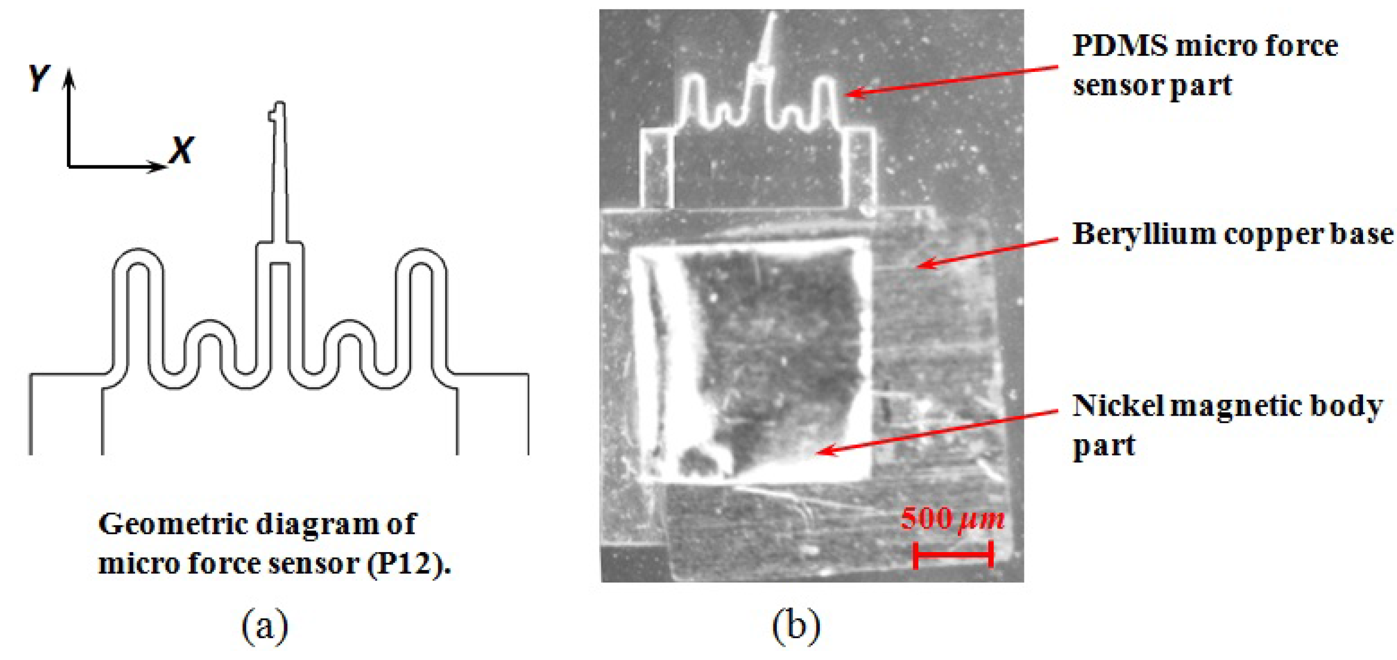
One example prototype is shown in Figure 4. This prototype corresponds to the P12 design configuration in [30] and is depicted in Figure 4a. The fabrication result shows clean cut of the geometry. The device was fabricated with a larger thickness for better mechanical strength, because the soft workpiece is easy to bend and crash during the handling and transportation. In addition, thicker part is also easier for the releasing process after the fabrication. The stiffness of the micro force sensor will be analyzed and calibrated in the following section.
Figure 3.
The fabrication process of μFSMM prototype. (a) The microfabrication process of the micro force sensor. (b) Assembly of integrated prototype.
Figure 3.
The fabrication process of μFSMM prototype. (a) The microfabrication process of the micro force sensor. (b) Assembly of integrated prototype.

Figure 4.
Example of μFSMM prototyping result. (a) The design diagram of corresponding micro force sensor. (b) Photograph of final resulting assembly.
Figure 4.
Example of μFSMM prototyping result. (a) The design diagram of corresponding micro force sensor. (b) Photograph of final resulting assembly.

5. Calibration
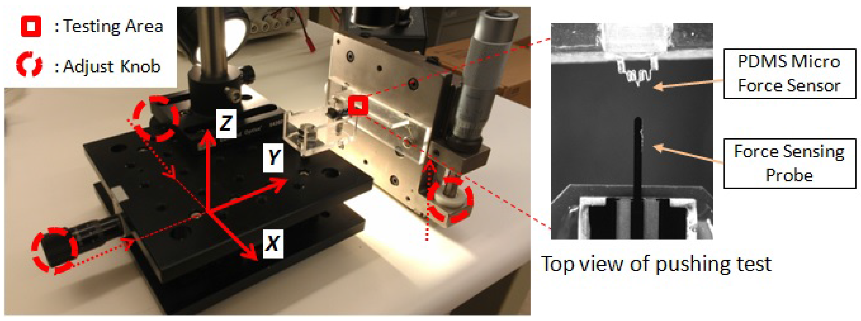
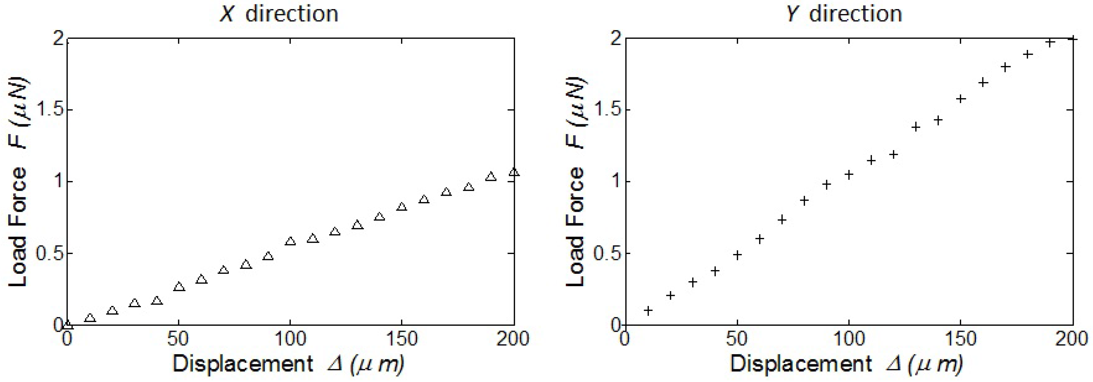
The prototype is experimentally calibrated with a micro force sensing probe (FT-S1000, FemtoTools, Zurich, Switzerland) as shown in Figure 5. The micro force sensing probe is able to sense the force in the range of ±1, 000 μN and with resolution of 0.05 μN at 10 Hz sampling frequency. The μFSMM prototype is set along X and Y directions with tip right against the force sensing probe. Therefore, the traveled distance of the micro force sensing probe is also the deflection of the micro force sensor on μFSMM. Both tests along X and Y direction are repeated three times, and the average of the results are plotted in Figure 6. The standard deviations of the stiffness are 3.0 × 10⁻⁴ N/m and 3.7 × 10⁻⁴ N/m on the X and Y directions, respectively. For both results of simulation and measurement, the stiffness in X direction is lower than that in Y direction. From the summarized stiffness results of the micro force sensor (Table 2), it is noted that the experimentally tested stiffness is higher than the simulation result of original design. The result shows that the thicker fabricated device layer will increase the stiffness as expected, but does meet the design requirement.
Figure 5.
The experimental setup for the calibration of micro force sensor. The position of micro force sensor and force sensing probe is adjusted by linear motion stages with resolution under 20 μm.
Figure 5.
The experimental setup for the calibration of micro force sensor. The position of micro force sensor and force sensing probe is adjusted by linear motion stages with resolution under 20 μm.

Figure 6.
The experimental calibration of the micro force sensor part on μFSMM. The micro force sensing probe pushes the tip of PDMS part at low speed (0.01 mm/s). The stiffness of the PDMS force sensor is fitted with the test results as Kx ≈ 0.00534 N/m, Ky ≈ 0.0105 N/m.
Figure 6.
The experimental calibration of the micro force sensor part on μFSMM. The micro force sensing probe pushes the tip of PDMS part at low speed (0.01 mm/s). The stiffness of the PDMS force sensor is fitted with the test results as Kx ≈ 0.00534 N/m, Ky ≈ 0.0105 N/m.

| Kx (N/m) | Ky (N/m) | |
|---|---|---|
| Design criteria | 0.014 | 0.014 |
| FEA-design parameters | 0.0012 | 0.0070 |
| Experimental measurements | 0.0053 | 0.0105 |
6. Characterization
6.1. Mobility
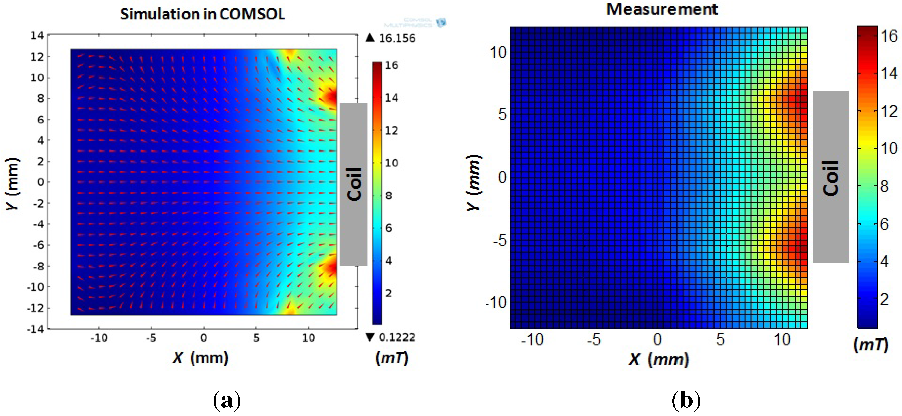
The fundamental purpose of this μFSMM design is to serve as a mobile microrobot. Therefore, the mobility of this magnetic assembly is tested with the electromagnetic coil system which is described in [11]. Before inducing the 2D motion of μFSMM agent by the side coils of the coil system, the produced magnetic field on the horizontal plane is analyzed through FEA model in COMSOL software (Figure 7a). The coil is able to produce straight magnetic field in the central area of workspace. The magnetic field is also verified with measurements using Gauss meter (GM1-ST, AlphaLab Inc., West Salt Lake City, UT, USA). The field strengths are measured at the grid points of 5 × 5 isometric mesh of the workspace and the field is interpolated based on the measurements, as shown in Figure 7b.
Figure 7.
The magnetic field actuating the μFSMM microrobot. (a) The FEA model using COMSOL software for a single coil. (b) The magnetic field measurements at discrete points in workspace using Gauss meter. Both input currents are 1.0 A in the coil.
Figure 7.
The magnetic field actuating the μFSMM microrobot. (a) The FEA model using COMSOL software for a single coil. (b) The magnetic field measurements at discrete points in workspace using Gauss meter. Both input currents are 1.0 A in the coil.
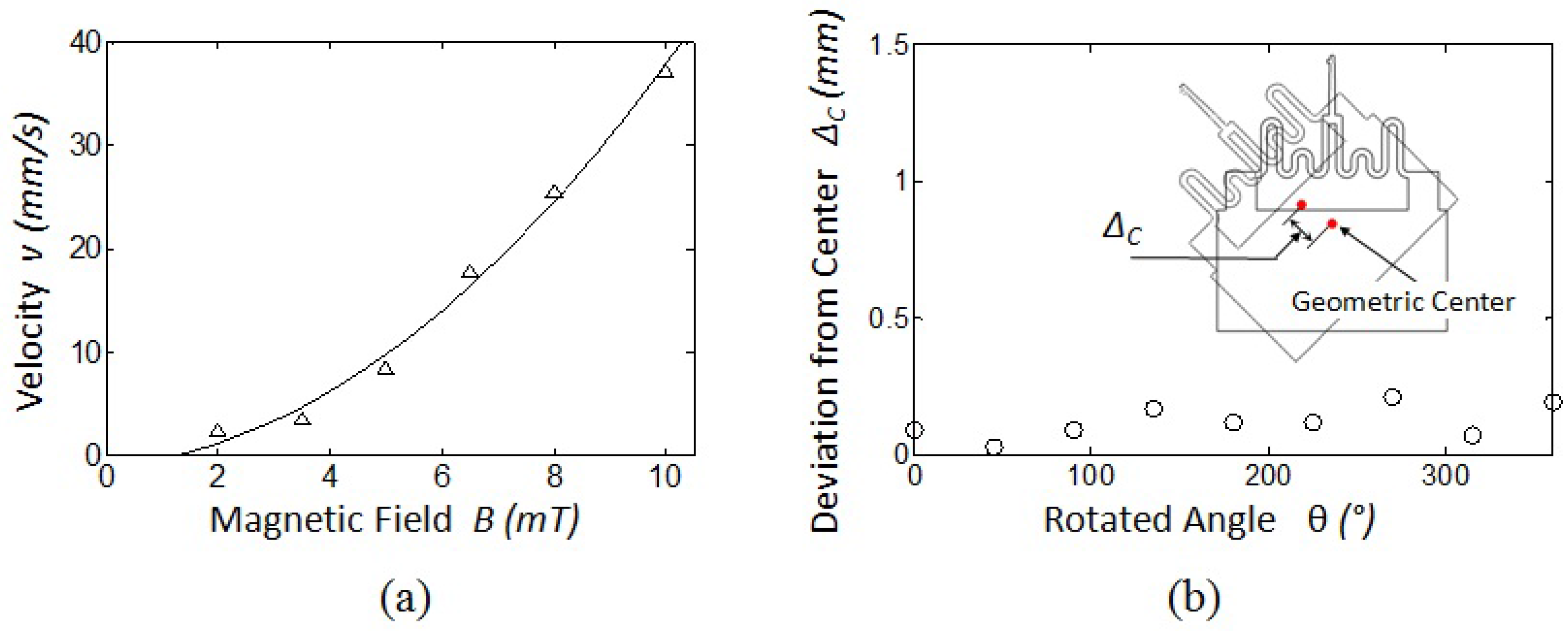
With the electromagnetic coil drive system, this P12 μFSMM prototype (Figure 4) is able to translate in DI water with current input as low as 0.05 A. A series of translation tests are conducted under increasing magnetic field flux intensities, where the average velocities during translations are shown in Figure 8a. The microrobot demonstrates good mobility with low magnetic field intensity levels. The agent has also been rotated under a rotating magnetic field signal. The deviation of the geometric center point from its original position has been recorded in Figure 8b. The small deviation shows stable controllability of the orientation of the μFSMM agent.
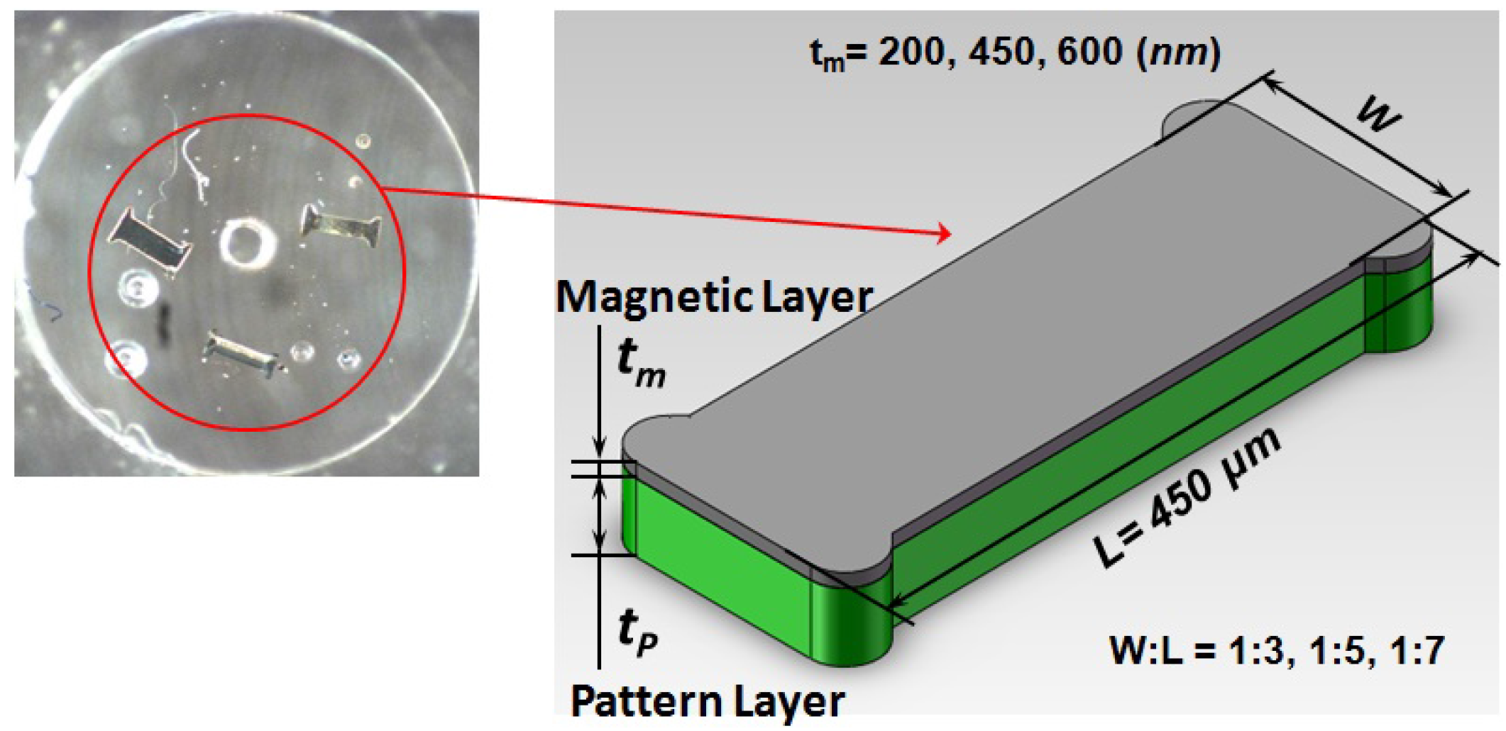
Moreover, the eventual μFSMM is targeting biomedical tasks on the microscale, where the robot is required to own a footprint at the μm level. The mobility of such a microscale magnetic structure has been tested using the microscale I-bar shaped prototype (Figure 9). The outline of this planar structure is patterned through an SU-8 photoresist layer and magnetic layer made of nickel by physical vapor deposition. The rectangular geometry of this agent is varied to investigate its affects on mobility in a fluid environment, where the linear motion results in DI water are summarized in Table 3. It shows that thicker magnetic layer leads to faster speed, which indicates the magnetic volume plays a significant role for the mobility. For the same magnetic volume, the larger aspect ratio of the rectangular shape has better mobility. This is indicated by increasing velocity results on the main diagonal in Table 3. These rules can serve as reference for the future design of a fully microscale μFSMM agent.
Figure 8.
The results of the mobility tests for the μFSMM prototype. (a) Linear translation velocity vs. magnetic field flux intensity. (b) The deviation of geometric center point when the prototype is rotated with 360°.
Figure 8.
The results of the mobility tests for the μFSMM prototype. (a) Linear translation velocity vs. magnetic field flux intensity. (b) The deviation of geometric center point when the prototype is rotated with 360°.

Figure 9.
The design of I-bar shape micro magnetic agent. The inset photograph shows the fabricated prototypes.
Figure 9.
The design of I-bar shape micro magnetic agent. The inset photograph shows the fabricated prototypes.

| Velocity | (mm/s) | ||
|---|---|---|---|
| tm (nm) | AR 1:3 | AR 1:5 | AR 1:7 |
| 200 | 1.55 | 1.29 | 1.10 |
| 400 | 4.70 | 4.27 | 3.64 |
| 600 | 10.24 | 9.21 | 6.02 |
Note: (1) AR means the aspect ratio for W : L. (2) The motion tests are conducted in DI water environment. The input current is 0.5 A and the magnetic field is 2 mT.
6.2. Calibration of Input Current to Force Relationship
The purpose of this μFSMM design is to couple a micro force sensing end-effector with a mobile microrobot. In practical microrobot applications, the blocking force acting on the robot body is due to the motion/momentum of the mobile microrobot. In the scenario of our magnetic mobile microrobot system, the sensed micro force corresponds to the current input into the electromagnetic drive coil. The sensed blocking force depends on the motion of μFSMM agent, which relies on the magnetic field generated by the drive coil. Therefore, with a calibrated micro force sensor, the in situ force can be derived through the current input into the drive coil. This relation is examined here with the prototype calibrated in previous section (Ky = 0.0105 N/m).
The microrobot assembly is powered with a known current input and driven against an obstacle (wall), which blocks the agent in the Y direction. The blocking force can be evaluated by the exerting magnetic force, which depends on the derived magnetic field due to the current input. The resultant deflection is recorded and the corresponding blocking force is then backed out based on the known stiffness of the micro force sensor. Therefore, the acting force on the magnetic mobile microrobot can be calibrated with the vision based micro force sensor.
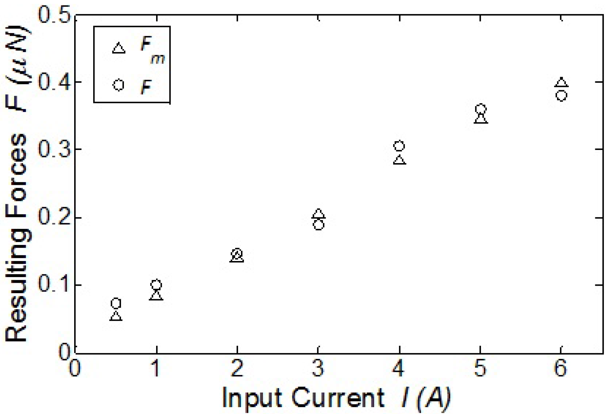
A series of calibration tests have been conducted with increasing current input I: 0.5A, 1.0A, 2.0A, 3.0A, 4.0A, 5.0A, 6.0A. After the producing magnetic field is assessed with simulation and measurement, the exerting magnetic force is calculated with Equation (1). At the same time, the corresponding force is also calculated by the resultant deflection of PDMS micro force sensor with known stiffness. The series of resulting forces are compared in Figure 10. The maximum differential is 0.021 μN (≈ 5% error), which shows good consistency between driving the magnetic microrobot and the micro force sensing. Because the acting force is proportional to the current input, this linear relation can be fitted according to the calibration result with force sensor (Figure 10) as F (μN) = 0.0634 × I (A), where F is the acting force and I is the input current.

7. Conclusions and Future Work
This paper describes a micro force sensing mobile microrobot (μFSMM). It is the first mobile microrobot with in situ force sensing capabilities. The micro force sensing module is realized through a 2D vision based compliant mechanism end-effector made of PDMS, which is able to detect the forces at low μN down to nN levels. This micro force sensor module is experimentally tested with a micro force sensing probe. A magnetic layer is attached to the micro force sensor which serves as drive part of the microrobot assembly. The sensed force is also calibrated against the acting magnetic force. This builds up the relation between the micro force and the current input to the electromagnetic coil for the magnetic microrobot drive system.
The work presented here only includes the preliminary analysis and prototyping as a proof-of-concept. Comprehensive experimentation is required before real biomedical applications for this μFSMM design can be realized. The calibration is needed mainly due to the errors generated during the fabrication process. Although the manufactured prototype still meets the design requirement, the deviation of geometric parameters will increase the stiffness of the micro force sensor. Moreover, the eventual μFSMM agent is intended to own a footprint at μm level. Therefore, it is critical to control the accuracy of the fabrication process. In addition to the PDMS micro force sensor end-effector, the magnetic drive part also needs precise fabrication methods at the microscale, such as the photolithography process proposed in [11], or physical and chemical etching process to outline the magnetic volume. This is also important because magnetic volume determines the acting force on the microrobot, which requires delicate calibration. Nevertheless, this proof-of-concept work presented here proves the possibility of incorporating a force sensing function in the magnetic microrobot system that is desirable for biomedical tasks at the microscale.
Acknowledgements
The authors gratefully acknowledge the support of NSF IIS Award # 1149827.
Authors Contributions
David Cappelleri came up with the idea for creating a magnetic microrobot with a vision-based micro-force sensor. The magnetic microrobot body design is based on the work of Wuming Jing. The vision-based micro-force sensor design is based on the work of Cappelleri. Both authors equally contributed to the fabrication process design and fabrication of the prototypes. Jing performed the calibration and characterization analysis and wrote the paper.
Conflicts of Interest
The authors declare no conflict of interest.
References
- Dong, L.; Nelson, B.J. Robotics in the small, part 2: Nanorobotics. IEEE Robot. Autom. Mag. 2007. [Google Scholar] [CrossRef]
- Fatikow, S.; Rembold, U. Microsystem Technology and Microrobotics; Springer: New York, NY, USA, 1997. [Google Scholar]
- Donald, B.R.; Levey, C.G.; McGray, C.D.; Paprotny, I.; Rus, D. An Untethered, Electrostatic, Globally Controllable MEMS Micro-Robot. J. Microelectromech. Syst. 2006, 15, 1–15. [Google Scholar] [CrossRef]
- Sul, O.J.; Falvo, M.R.; Taylor, R.M.; Washburn, S.; Superfine, R. Thermally actuated untethered impact-driven locomotive microdevices. Appl. Phys. Lett. 2006. [Google Scholar] [CrossRef]
- Zhang, L.; Abbott, J.; Dong, L.; Kratochvil, B.E.; Bell, D.; Nelson, B.J. Artificial bacterial flagella: Fabrication and magnetic control. Appl. Phys. Lett. 2009, 94, 064107:1–064107:3. [Google Scholar] [CrossRef]
- Frutiger, D.R.; Vollmers, K.; Kratochvil, B.E.; Nelson, B.J. Small, Fast, and Under Control: Wireless Resonant Magnetic Micro-agents. Int. J. Robot. Res. 2010, 29, 613–636. [Google Scholar] [CrossRef]
- Tung, H.W.; Frutiger, D.R.; Pan�, S.; Nelson, B.J. Polymer-Based Wireless Resonant Magnetic Microrobots. In Proceedings of the IEEE International Conference on Robotics and Automation (ICRA), St. Paul, MN, USA, 14–18 May 2012.
- Pawashe, C.; Floyd, S.; Sitti, M. Modeling and experimental characterization of an untethered magnetic micro-robot. Int. J. Robot. Res. 2009, 28, 1077–1094. [Google Scholar] [CrossRef]
- Jiang, G.L.; Guu, Y.H.; Lu, C.N.; Li, P.K.; Shen, H.M.; Lee, L.S.; Yeh, J.A.; Hou, M.T.-K. Development of rolling magnetic microrobots. J. Micromech. Microeng. 2010, 20, 085042. [Google Scholar] [CrossRef]
- Tung, H.W.; Peyer, K.E.; Sargent, D.F.; Nelson, B.J. Noncontact manipulation using a transversely magnetized rolling robot. Appl. Phys. Lett. 2013, 103, 114101. [Google Scholar] [CrossRef]
- Jing, W.; Pagano, N.; Cappelleri, D.J. A novel micro-scale magnetic tumbling microrobot. J. Micro-Bio Robot. 2013, 8, 1–12. [Google Scholar] [CrossRef]
- Jing, W.; Pagano, N.; Cappelleri, D. A Tumbling Magnetic Microrobot with Flexible Operating Modes. In Proceedings of the IEEE International Conference on Robotics and Automation (ICRA), Karlsruhe, Germany, 6–10 May 2013.
- Abbott, J.J.; Ergeneman, O.; Kummer, M.; Hirt, A.M.; Nelson, B.J. Modeling Magnetic Torque and Force for Controlled Manipulation of Soft-Magnetic Bodies. IEEE Trans. Robot. 2007, 23, 1247–1252. [Google Scholar] [CrossRef]
- Kummer, M.; Abbott, J.J.; Kratochvil, B.E.; Borer, R.; Sengul, A.; Nelson, B.J. OctoMag: An Electromagnetic System for 5-DOF Wireless Micromanipulation. IEEE Trans. Robot. 2010, 26, 1006–1017. [Google Scholar] [CrossRef]
- Tabatabaei, S.N.; Lapointe, J.; Martel, S. Shrinkable Hydrogel-Based Magnetic Microrobots for Interventions in the Vascular Network. Adv. Robot. 2011, 25, 1049–1067. [Google Scholar] [CrossRef]
- Sun, Y.; Nelson, B. MEMS for cellular force measurements and molecular detection. Int. J. Inf. Acquis. 2004, 1, 23–32. [Google Scholar] [CrossRef]
- Li, X.; Su, D.; Zhang, Z. A novel technique of microforce sensing and loading. Sens. Actuators A: Phys. 2009, 153, 13–23. [Google Scholar] [CrossRef]
- Gnerlich, M.; Perry, S.F.; Tatic-Lucic, S. A submersible piezoresistive MEMS lateral force sensor for a diagnostic biomechanics platform. Sens. Actuators A: Phys. 2012, 188, 111–119. [Google Scholar] [CrossRef]
- Hoover, A.; Fearing, R. Rapidly prototyped orthotweezers for automated microassembly. In Proceedings of the IEEE International Conference on Robotics and Automation (ICRA), Roma, Italy, 10–14 April 2007.
- Perez, R.; Chaillet, N.; et al. Fabrication, modeling and integration of a silicon technology force sensor in a piezoelectric micro-manipulator. Sens. Actuators A: Phys. 2006, 128, 367–375. [Google Scholar] [CrossRef] [Green Version]
- Beyeler, F.; Nelid, A.; Oberti, S.; Bell, D.J.; Sun, Y.; Dual, J.; Nelson, B.J. Monolithically Fabricated Microgripper With Integrated Force Sensor for Manipulating Microobjects and Biological Cells Aligned in an Ultrasonic Field. J. Microelectromech. Syst. 2007, 16, 7–15. [Google Scholar] [CrossRef]
- Beyeler, F.; Muntwyler, S.; Nelson, B.J. A Six-Axis MEMS Force? Torque Sensor With Micro-Newton and Nano-Newtonmeter Resolution. J. Microelectromech. Syst. 2009, 18, 433–441. [Google Scholar] [CrossRef]
- Koch, S.J.; Thayer, G.E.; Corwin, A.D.; de Boer, M.P. Micromachined piconewton force sensor for biophysics investigations. Appl. Phys. Lett. 2006, 89, 173901. [Google Scholar] [CrossRef]
- Wang, X.; Ananthasuresh, G.; Ostrowski, J. Vision-based sensing of forces in elastic objects. Sens. Actuators A: Phys. 2001, 94, 142–156. [Google Scholar] [CrossRef]
- Greminger, M.; Nelson, B. Vision-based force measurement. IEEE Trans. Pattern Anal. Mach. Intell. 2004, 26, 290–298. [Google Scholar] [CrossRef] [PubMed]
- Jeong, K.H.; Keller, C.; Lee, L. Direct force measurements of biomolecular interactions by nanomechanical force gauge. Appl. Phys. Lett. 2005, 86, 193901. [Google Scholar] [CrossRef]
- Ioppolo, T.; Kozhevnikov, M.; Stepaniuk, V.; Otugen, M.V.; Sheverev, V. Micro-optical force sensor concept based on whispering gallery mode resonators. Appl. Opt. 2008, 47, 3009–3014. [Google Scholar] [CrossRef] [PubMed]
- Sasoglu, F.; Bohl, A.; Layton, B. Design and microfabrication of a high-aspectratio pdms microbeam array for parallel nanonewton force measurement and protein printing. J. Micromech. Microeng. 2007, 17, 623–632. [Google Scholar] [CrossRef]
- Liu, X.; Kim, K.; Zhang, Y.; Sun, Y. Nanonewton force sensing and control in microrobotic cell manipulation. Proc. Robot.: Sci. Syst. iv@ 2009, 28, 1065–1076. [Google Scholar]
- Cappelleri, D.J.; Piazza, G.; Kumar, V. A two dimensional vision-based force sensor for microrobotic applications. Sens. Actuators A: Phys. 2011, 171, 340–351. [Google Scholar] [CrossRef]
- Sia, S.K.; Whitesides, G.M. Microfluidic devices fabricated in Poly(dimethylsiloxane) for biological studies. Electrophoresis 2003, 24, 3563–3576. [Google Scholar] [CrossRef] [PubMed]
- Fox, R.W.; McDonald, A.T. Introduction to Fluid Mechanics; John Wiley & Sons, Inc.: Hoboken, NJ, USA, 1992. [Google Scholar]
© 2014 by the authors; licensee MDPI, Basel, Switzerland. This article is an open access article distributed under the terms and conditions of the Creative Commons Attribution license (http://creativecommons.org/licenses/by/3.0/).
Share and Cite
MDPI and ACS Style
Jing, W.; Cappelleri, D. A Magnetic Microrobot with in situ Force Sensing Capabilities. Robotics 2014, 3, 106-119. https://doi.org/10.3390/robotics3020106
AMA Style
Jing W, Cappelleri D. A Magnetic Microrobot with in situ Force Sensing Capabilities. Robotics. 2014; 3(2):106-119. https://doi.org/10.3390/robotics3020106
Chicago/Turabian StyleJing, Wuming, and David Cappelleri. 2014. "A Magnetic Microrobot with in situ Force Sensing Capabilities" Robotics 3, no. 2: 106-119. https://doi.org/10.3390/robotics3020106