3.1. Review of Aerodynamic Characteristics of Corrugated Wing through Visualization
The fact that dragonfly wings are corrugated is well known, and by using the profile data for Lesser Emperors given in [
9], we attempted to clarify the two-dimensional flow around the wings of the Lesser Emperor by using the original visualization method by using aluminum powder. As shown in [
8], we found that the dragonfly’s corrugated wing plays an important role in producing lift and stability during flight for Reynolds (Re.) numbers between 2000 and 7000. An actual dragonfly seems to glide in around Re.2000 in calm condition, but the flow phenomena in a higher Re. number condition is interesting from the view point of application, so the experiment was achieved to maximum Re. flow in which our visualization technique is effective.
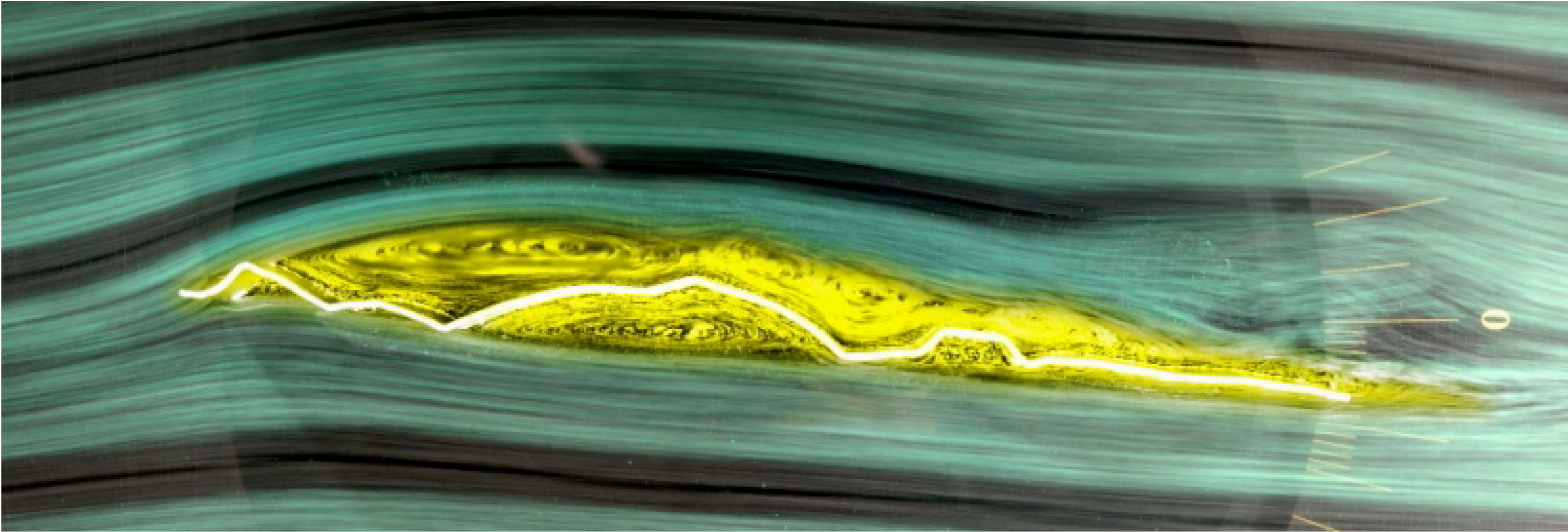
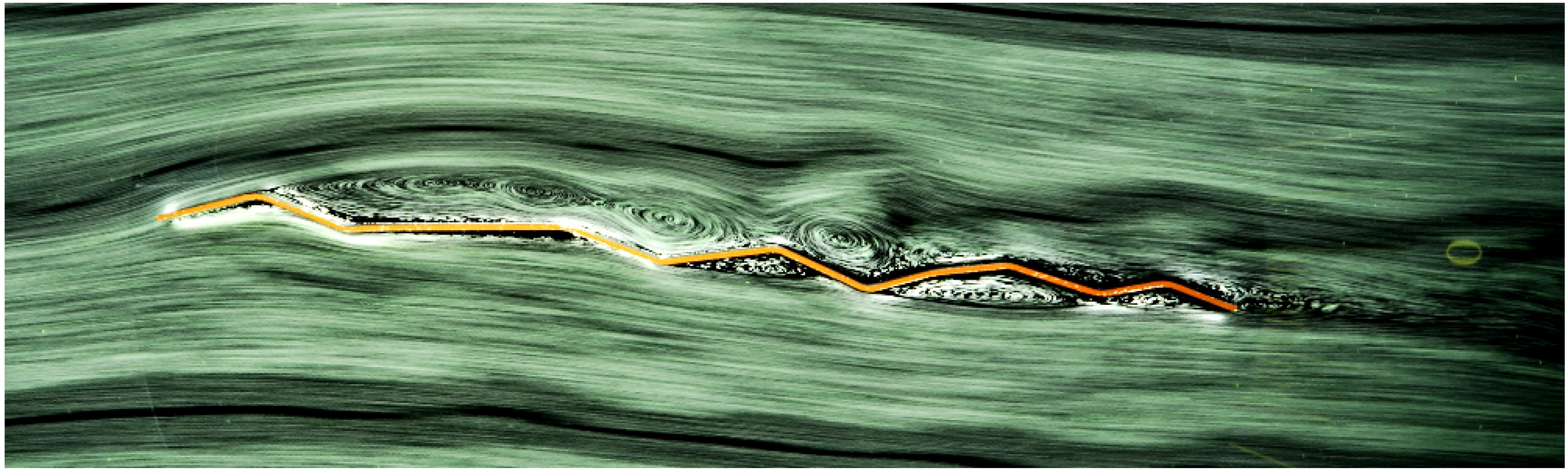
The two-dimensional flow experiments showed that in gliding flight, the dragonfly produces vortex trains on the upper surfaces of their corrugated wings, which blow off congested air that forms due to the viscosity at the upper surfaces. The result is streamline airflow around the corrugated wing. The typical airflow pattern of a dragonfly is shown in
Figure 2 where the yellow area denotes vortex flow.
Figure 2.
Flow around a Lesser Emperor’s wing at Re.7000 (hind wing, 75% half-span section, angle of attack is 5°).
Figure 2.
Flow around a Lesser Emperor’s wing at Re.7000 (hind wing, 75% half-span section, angle of attack is 5°).
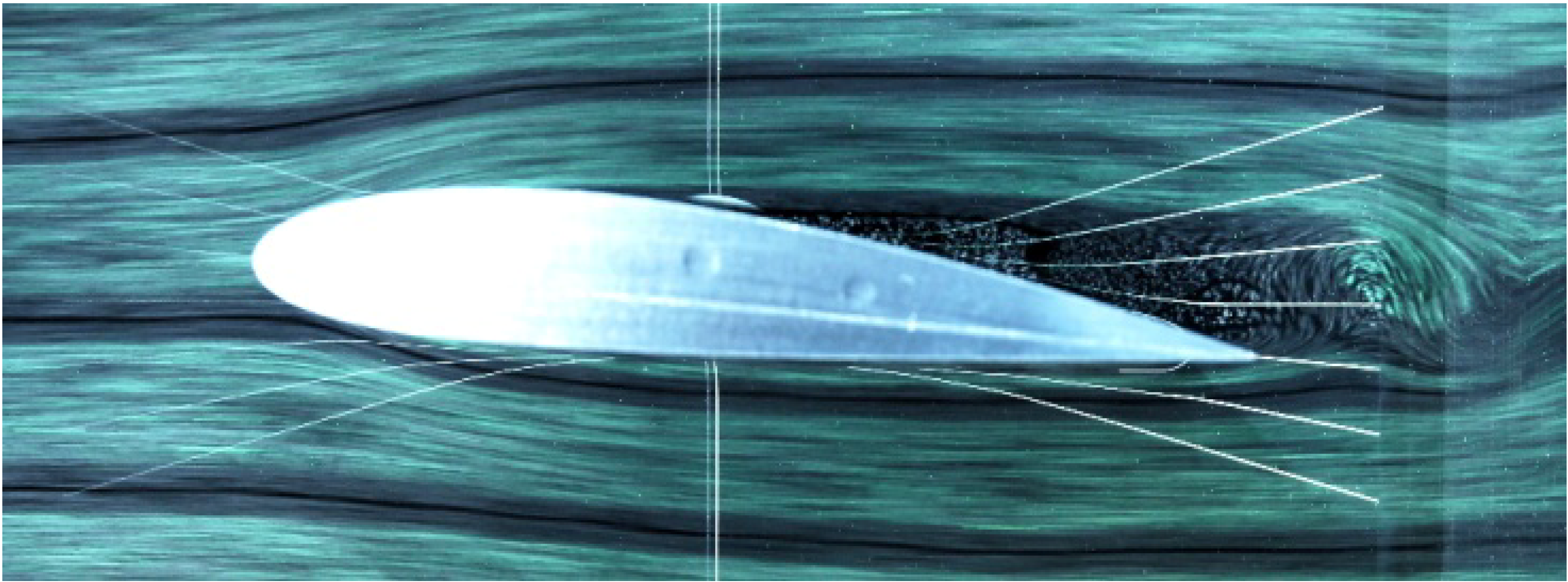
The flow around NACA 4418 is shown in
Figure 3, in which the Re. number is 7000 and the angle of attack is 5°.
Figure 3.
Flow around NACA4418 wing (angle of attack is 5°).
Figure 3.
Flow around NACA4418 wing (angle of attack is 5°).
The difference between this wing and the dragonfly wing is notable. In low Re. number flow, the growth of the congested area is especially apparent on the upper surface of NACA 4418, generating undesirable flow pattern characteristics and ultimately reducing lift. On the other hand, the congested flow on the dragonfly wing is blow away by the vortex train and reforms the streamline airfoil shape so as to generate lift.
The modeled 2-D wing is not identical to an actual dragonfly’s 3-D wing, but flow around the 2-D wing gives enough information when application to fixed wing flying object is considered.
Now, it is apparent that NACA 4418 is not suitable to low Re. number flight, but it is possible to improve by using thinner streamlined wing [
9]. Aerodynamic characteristics of thin curved plate seem not inferior to corrugated wing as far as the polar curve is considered [
9].
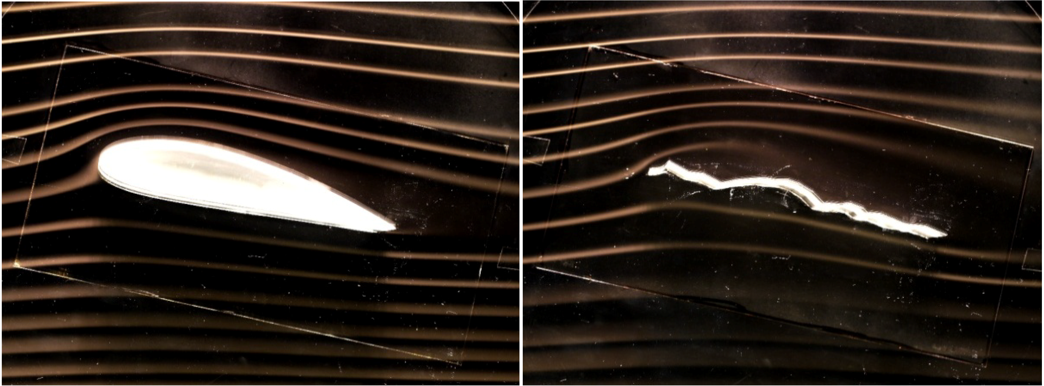
To understand the behaviors of wings in turbulent condition, we set the curved plate wing and corrugated wing in a steady flow, and once the condition of the congested region has stabilized, we rapidly accelerated the wing and observed the resulting change in airflow. In the case of the curved plate wing, half of the grown congested area was blown off by the acceleration and the shape of the streamline flow changed. In the case of the corrugated wing, however, the shape of the streamline did not change at all, but the strength of vortices increased to compensate for the accelerated flow [
8]. The flow mechanism for a curved plate wing is shown schematically in
Figure 4.
Figure 4.
Schematic diagram of wing acceleration effect.
Figure 4.
Schematic diagram of wing acceleration effect.
The actual flight of such a wing is complicated, because after accelerating the congested area grows again to a steady state, resulting in pilots being unable to understand the aerodynamic situation as they cannot see the change in air flow.
Figure 4 suggests that for the curved plate wing or a thin streamlined wing with a positive camber, it is very difficult to manage this unstable aerodynamic behavior. The corrugated wing, however, is unaffected by these changes of circumstance and is able to maintain steady flight. This suggests that fixed wing robots with corrugated wings are able to fly in turbulent air at low Re. numbers in the same way that conventional aircraft fly at high Re. numbers. The Re. number in the above experiment was 7000 but the Re. number expected in the actual flights of developed robots is in the order of tens of thousands and it remains some degree of discrepancy in Re. number.
As a means of precaution against unexpected behavior, we tried to visualize the flow using a wind tunnel generating smoke streamlines with a Re. number of 70,000 (
Figure 5). The flow did not deteriorate and we did not find any critical phenomena. We concluded that in the region of 7000 to 70,000, the performance of the corrugated wing may degrade gradually but does not show any abrupt change.
For reference, the flow around NACA 4418 was found to drastically improve at the Re. number of 70,000, and produces a better flow pattern than the corrugated wing (
Figure 6).
Figure 5.
Flow around a Lesser Emperor’s wing at Re.70,000 (hind wing, 75% half span section, angle of attack is 5°, photo does not show pure 2D section of wing).
Figure 5.
Flow around a Lesser Emperor’s wing at Re.70,000 (hind wing, 75% half span section, angle of attack is 5°, photo does not show pure 2D section of wing).
Figure 6.
Flow around NACA4418 and Lesser Emperor’s wing at Re.70,000 (angle of attack is 13°, photo does not show pure 2D section of wing).
Figure 6.
Flow around NACA4418 and Lesser Emperor’s wing at Re.70,000 (angle of attack is 13°, photo does not show pure 2D section of wing).
The outcome of these experiments encouraged us to try to make a flying robot with corrugated wings for flight at Re. numbers in the order of tens of thousands. At this stage, special fluid dynamics for measuring lift, drag, and moments was not required because it is sufficient to know the best position for the center of gravity and to use statically stable characteristics for each aircraft configuration to achieve flight.
We obtained the profile of the Wandering Glider’s wing through 3-D digital microscopy and tried the flow visualization for the wandering glider. The shape of the Wandering Glider’s wing is very different to that of the Lesser Emperor’s. However, there were few differences in the flow pattern and vortex train generation processes (
Figure 7), thus, the corrugated wings of the Lesser Emperor and Wandering Glider were chosen for the first dragonfly mimetic corrugated wing flying robots to find comparative merits and demerits.
Figure 7.
Flow around Wandering Glider’s wing at Re.7000 (forewing, 75% half span section, angle of attack is 5°).
Figure 7.
Flow around Wandering Glider’s wing at Re.7000 (forewing, 75% half span section, angle of attack is 5°).
3.2. Preliminary Mimetic Study of Dragonfly Gliding at Low Re. Numbers
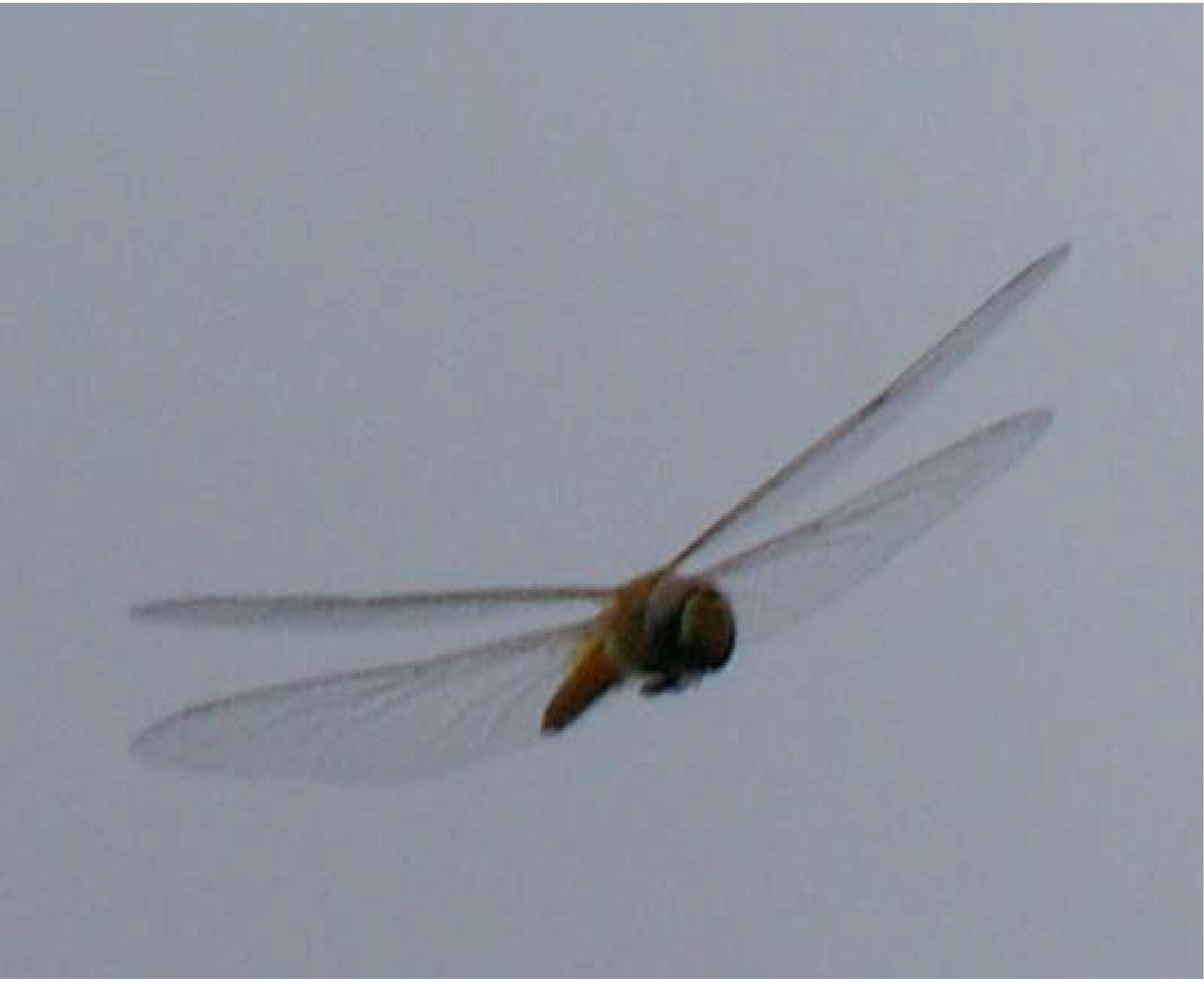
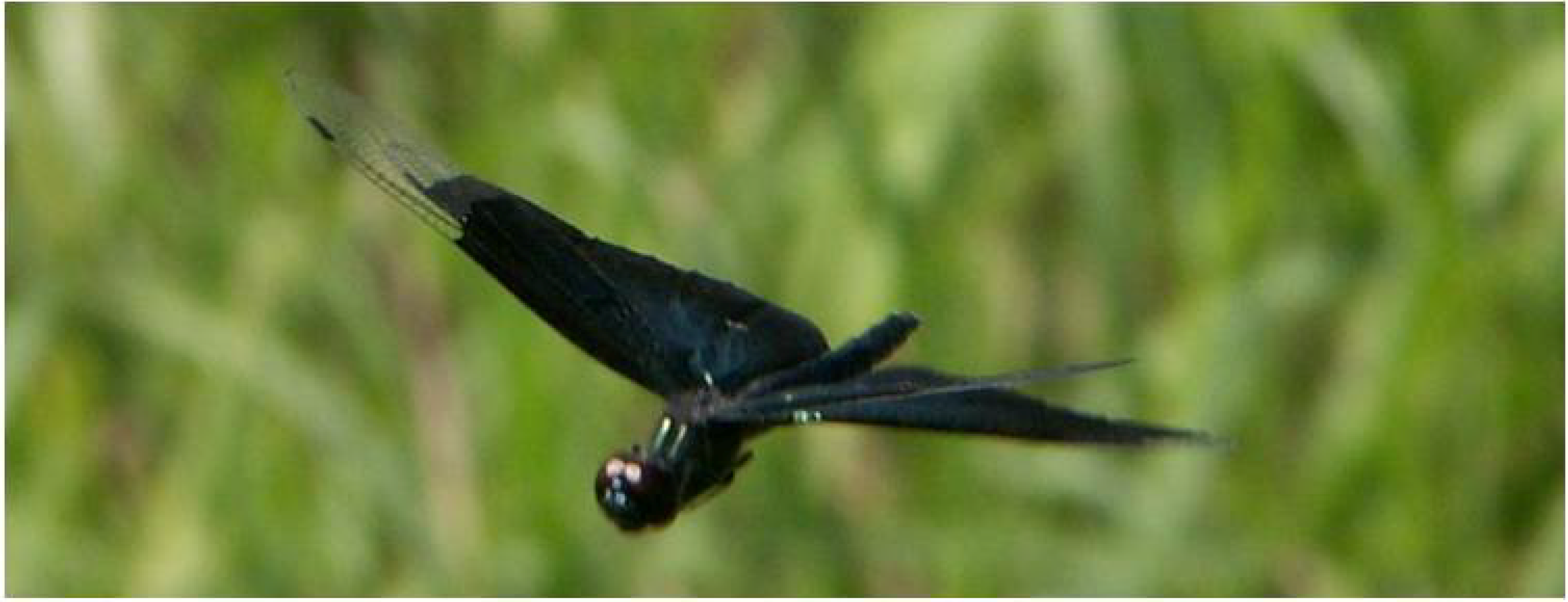
Photographs show that when gliding dragonflies use around 15° of forewing dihedral angle and either the same order for their hind wing or none at all (
Figure 8 and
Figure 9).
Figure 8.
A Wandering Glider gliding.
Figure 8.
A Wandering Glider gliding.
Figure 9.
A Rhyothemis fuliginosa gliding.
Figure 9.
A Rhyothemis fuliginosa gliding.
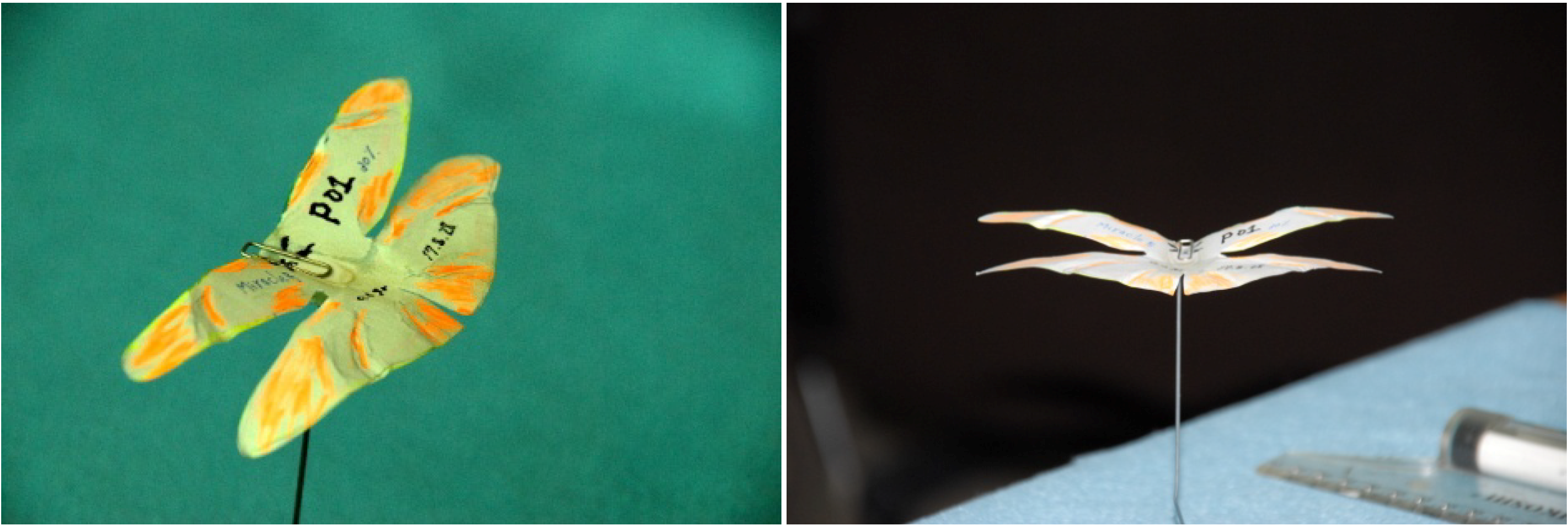
We made aircrafts, 12 cm in wing-span, using copying paper that consist of only wing and no fuselage applying general outline we have got about dragonfly (
Figure 10). At this stage, 3-D mimetics was intended. It weighed 0.6 g and showed remarkable straight flight tendency and the robustness to deformation with passage of time. Even after half a year of leaving, the plane in
Figure 10 flew straight without any adjustment work. A normal thin paper airplane is very subtle to deformation of the wing and delicate adjustment is required in each flight. This led us to further investigation of dragonfly’s gliding ability.
Figure 10.
Dragonfly paper plane without fuselage.
Figure 10.
Dragonfly paper plane without fuselage.
Considering the technical difficulty of 3-D mimetics of real dragonfly’s wings, we decided to investigate the effect of paper aircraft having corrugated but uniform wing section. To realize the tail boom of dragonfly, we had to make up sized airplanes of 15 cm in wing span and around 2.5 g in weight (
Figure 11).
Wing section profiles of the aircraft in
Figure 11 are different to dragonflies. This is one of artificial models obtained from flow visualization test at Re.2000 (
Figure 12), but later it is replaced with a dragonfly-like section because of its toughness to high speed and turbulences.
Figure 11.
Dragonfly paper plane having head and fuselage and catapult.
Figure 11.
Dragonfly paper plane having head and fuselage and catapult.
Figure 12.
.Flow around simplest corrugated wing at Re.2000.
Figure 12.
.Flow around simplest corrugated wing at Re.2000.
The aspect ratio was made to be the same as that of a gliding dragonfly, and the position of the center of gravity and the mounting angle of the hind wing were determined through flight experiments. The mounting angle used for the wings of normal tailless airplanes was equated for the case of twin wings, like those of a dragonfly, to the hind wing leading edge is lower than trailing edge. The best performance was achieved with 30% whole wings chord position of center of gravity, wherein the chord is the distance from the leading edge of the forewing to the trailing edge of the hind wing, and achieved at the 15° of the leading edge lower installation angle of the hind wing.
Flight testing of best 15 cm span model revealed that the dihedral forewing and horizontal hind wing configuration achieved a lift-drag ratio of 6, which is better than the configuration in which both wings have a non-zero dihedral angle. Thus, we adopted this configuration as standard for gliding models thereafter. Experiments with wing-only models in outdoor conditions suggested that the effect of wind is too strong for stable flight.
A paper aircraft with a head and fuselage achieved more stable flight compared to the wing-only model. The addition of a head and fuselage changes the balance of the moment of inertia of the flying object.
The mass distribution of the paper plane with no fuselage was wide, whereas those with a head and fuselage had an almost square distribution. The later models have the potential to resist the large rolling moments induced by gusts. When the moment of inertia around the principal axis is divided into moments large, medium, and small in magnitude, and when they start to rotate, it is known that the rotating motion around the axis having the medium size of moment of inertia diverges for almost every configuration [
10]. This information leads us to conclude that, for small-sized fixed-wing flying robots for outdoor use, we have to adopt the cruciform configuration of dragonflies, to avoid unstable dynamic movement about the rolling axis, because the rolling movements caused by gusts are far more significant than those of conventional large-sized aircraft. Foregoing discussion leads us to the design principle that the basic configuration of small fixed-wing aircraft with corrugated wings should have cruciform mass distribution.
The outdoor flying tests of paper aircraft with tandem corrugated wings and a head and tail showed superior robustness to side-on gusts compared to the wing-only type, as expected. New differences between the corrugated wing and the curved wing were found for the cruciform configuration through catapult flight tests against wind produced by a fan.
The latter aircraft was blown upwards or turned suddenly when it approached the fan, but the corrugated wing aircraft was able to maintain a straight flight until getting very close. This makes apparent an additional advantage of the corrugated wing.
3.3. Remotely Controlled Flying Robot with a Single Corrugated Wing
Ultra-lightweight flying toys with single wings that are controllable using infrared rays were easily realizable at the time we have started research. The next step in our experiment was in successfully exchanging the toy’s fuselage and wing with a single corrugated wing.
All the structural parts were manufactured by university students through this research. These models were mainly used to confirm the flight performance of corrugated wing in rather large Re. numbers than that of paper aircraft or of flow visualization experiment.
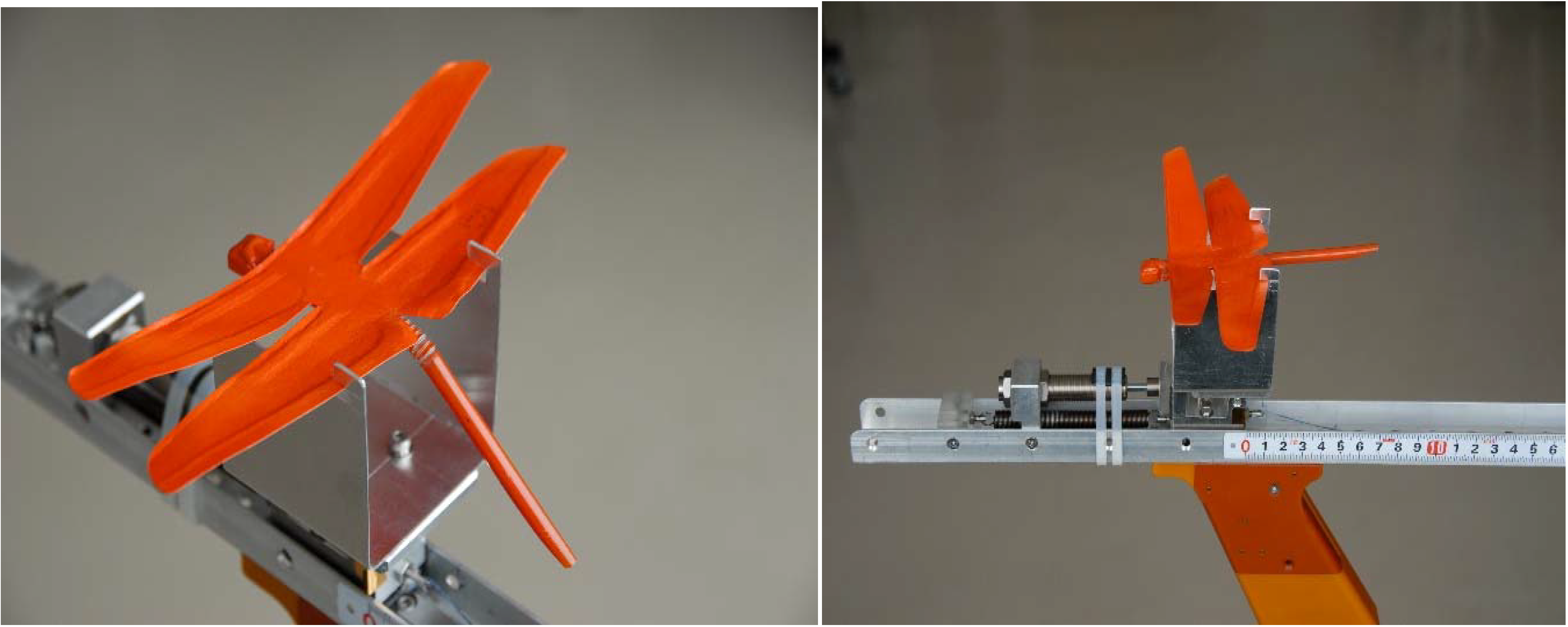
The span of the prototype robot was 18 cm and the mass was 4 g. The single pusher propeller and rudder configuration of the original model remained intact. The periphery of the wing was a CFRP frame and the inner surface of the wing was made from thin but rigid Japanese paper which allowed us to form the corrugated profile. Position of the center of gravity was set at nearly 30% of longest wing chord. We prepared two types of wing section, Lesser Emperor’s and Wandering Glider’s profiles at the 75% half unit span. The Lesser Emperor’s model was shown in
Figure 13. The black part of structure was made of CFRP and the white part of wing is made of Japanese paper. Base data of the wing section is digitalized on CATIA, and after the mold is machined, a heating and decompression device (1 atm. on gauge) was used for final CFRP forming.
Figure 13.
Ultra-light RC flying robot with a single corrugated wing.
Figure 13.
Ultra-light RC flying robot with a single corrugated wing.
Longitudinal stability was ensured by adopting the tail up reflection of the wing. The main experiment was conducted in a wide lecture room at NBU that was 10 m2 in size and 3 m in height.
Both wing types showed almost same flying characteristics for pilots. Lesser Emperor’s wing (
Figure 2) has larger maximum height (5% of chord) than that (3% of chord) of Wandering Glider’s wing (
Figure 7) and the position of maximum height is near the center chord, and is considered to have healthy structure for rough operation by pilots and selected as our standard wing section for robot.
The prototype robot showed surprising stability at the speed of 4 m/s. The chord length referenced Re. number was around 14,000 and, although it differed from that investigated using the water tunnel, the influence of the Re. number difference was not apparent. Two-channel remote control flying robots do not have control around the pitching axis so it is normal for such robots to exhibit oscillatory attitude immediately after changing altitude. The corrugated wing model, however, did not show any oscillatory movement and was easily able to fly close to the ceiling or desktops.
Figure 14.
RC flying robot hitting a balloon.
Figure 14.
RC flying robot hitting a balloon.
A flight speed of 4 m/s is relatively high for flight in the above mentioned lecture room, which would causes pilots difficulty if the airplane did not have excellent dynamic stability. However, it was possible to pilot the prototype robot into a balloon moored in the room.
Figure 14 shows the balloon-hitting trajectory of the robot digitally pasted over frames of the recorded video. This experiment confirmed the stability of the corrugated wing and suggested the flying robot was ready for outside testing. Since the infrared control system is too sensitive to sunlight for outdoor use, we developed a radio controlled flying robot.
3.4. Remotely Controlled Dragonfly Shaped Flying Robot with Corrugated Wings
The experimental model used for the flight tests had tandem wings like a dragonfly of which the wingspan was 27 cm and the mean chord was 3.5 cm. The total wing area was 189 cm2 and the mass was around 20 g.
The position of the center of gravity was around 30% of whole wing chord, which means the distance from the leading edge of the forewing to the trailing edge of the hind wing.
The installation angles of the wing to fuselage were determined using the results of the paper airplane experiments. Pusher type counter rotating propellers were installed under both forewings. Fortunately, propeller position between forewing and hind wing gives propellers a high lift generating function. Prop wash activates the dispirited upper surface flow of the hind wing in a high angle of attack and produce high lift and delays stall of the hind wing.
Velocity control was achieved by the collective operation of the rotational speed of both propellers and yawing was achieved by the differential operation of the propellers.
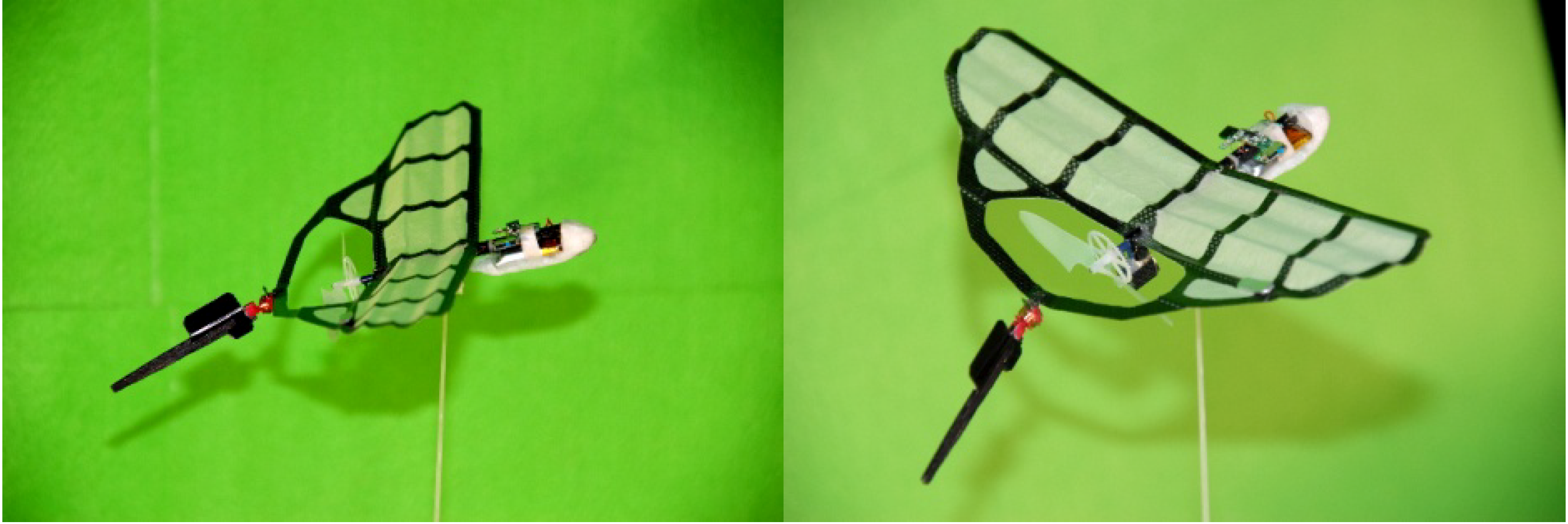
The command and control system and the power driving system were cannibalized from a flying toy (X-TWIN PRO STORM by Silverlit). Static thrust of both propellers was 18 g. The wing profile of the Lesser Emperor at 75% half unit span was adopted with a forewing dihedral angle of 15° and a horizontal hind wing. The early model of the wing was made from CFRP, which weighed 25 g, and was later improved to a periphery CFRP structure with a thin plastic film inner surface to reduce the weight to 17 g (
Figure 15). Fuselage structure, including the nose, was made of Japanese cypress considering experimental convenience and the nose was covered by EPP (expanded polypropylene).
Figure 15.
Dragonfly shaped RC flying robot with corrugated wings.
Figure 15.
Dragonfly shaped RC flying robot with corrugated wings.
Structure is simple and sturdy and born many times of unintentional collision shocks.
The battery (200 mAh, 5.47 g) was installed on the cypress bar just under the hind wing and control circuit board for radio control was attached to nose part of the cypress and covered by EPP.
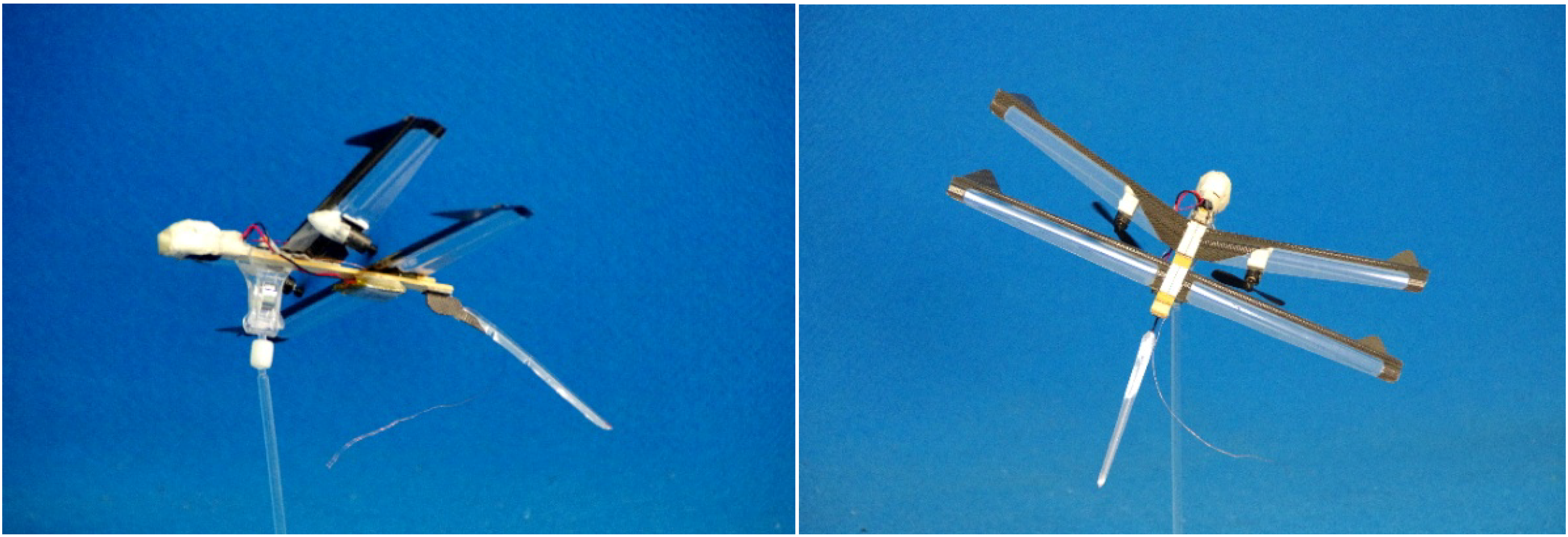
Forward facing delta winglets installed on the leading edges of the wing tips generated strong tip vortices and delayed stall.
The relatively large ventral fin under hind wing is attached when continuous high angle of attack flight is necessary and it was effective to attenuate the rolling oscillation occurring at a high angle of attack (
Figure 16).
The angle of the tail to the wing’s lower surface was made adjustable. It was mainly the university gymnasium that was used for indoor flight and the university athletic track and field on hilly terrain that was used for outdoor flight. This field receives a northerly wind during almost every day from Setonaikai Bay, located two miles north of the track. The dragonfly configured flying robot showed excellent stability, as expected. The speed at level flight was 6 m/s with the configuration of easiest control, obtained by adjusting the position of the center of gravity. The chord based Re. number was 14,000, the same as that for the former single winged ultra-lightweight flying robot. The fact that this robot encountered no problems in steep descents may indicate that corrugated wings were able to maintain the vortex chain and its effects up to an Re. number of 20,000.
Figure 16.
Dragonfly shaped RC flying robot for high angle of attack.
Figure 16.
Dragonfly shaped RC flying robot for high angle of attack.
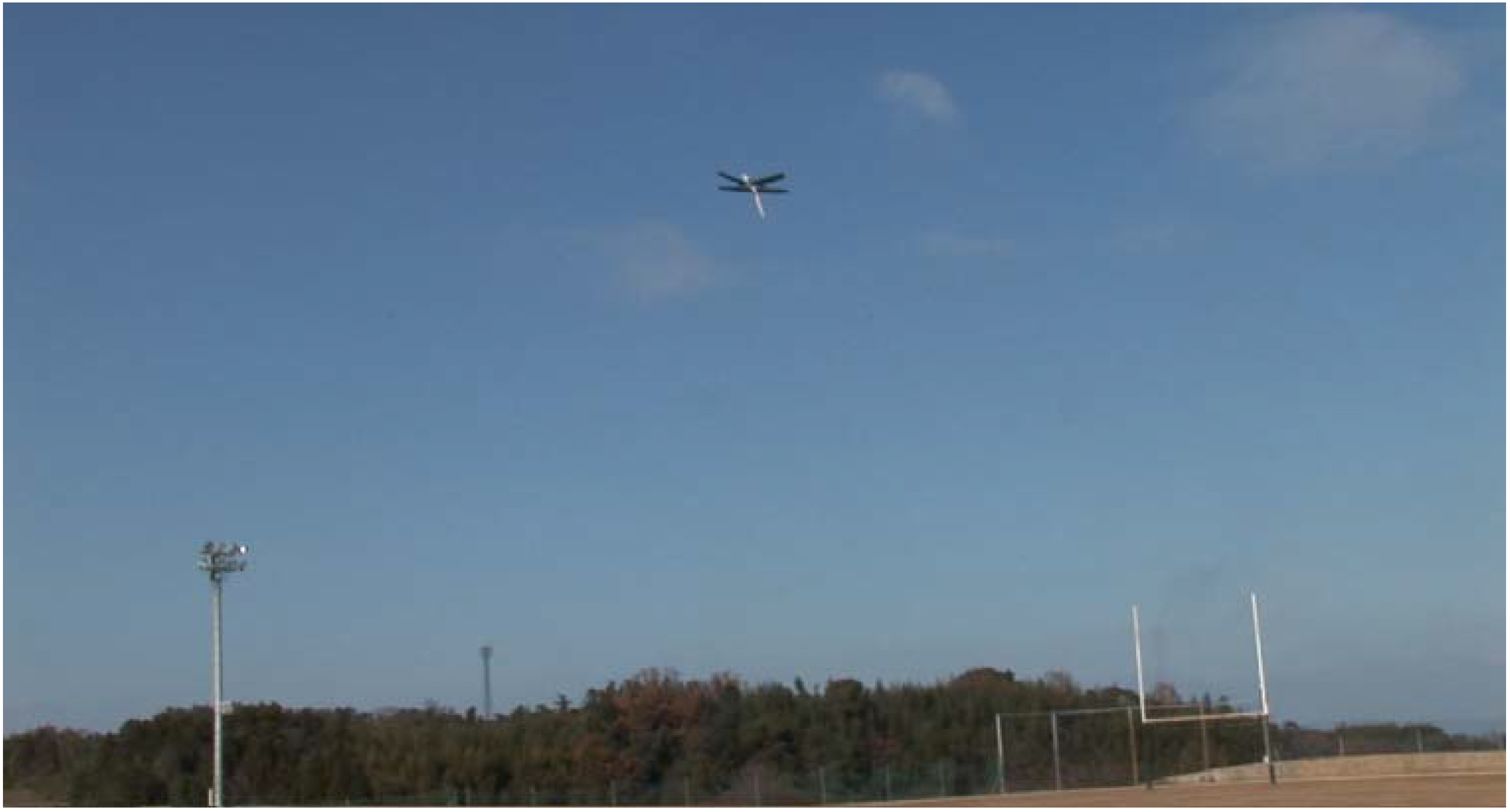
In indoor flight, the pilot was able to fly as desired using a two-channel control from low speed to relatively high speed. Both loops and pulling up near the ground were easy for skilled pilots. In outdoor flight, the robots kept their high flight stability, but it was necessary to set the center of gravity somewhat forward to decrease the angle of attack, since the change of angle of attack in outdoor flight due to the gusts and turbulence was far greater than that in indoor conditions. A flight over the track and field area is shown in
Figure 17. We found that if the tail was fitted at a greater angle to the wings (tail down), the robot seems to have increased stability. It is possible that the nose down moment induced by the bending of the tail reduces the angle of attack and lowers the likelihood of stalling. Furthermore, the tail-down configuration restricts the rolling movements of the robot caused by side-on gusts and alleviates the descent tendency by lift loss accompanied with rolling.
Figure 17.
Flying dragonfly robot over the NBU field.
Figure 17.
Flying dragonfly robot over the NBU field.
Forward facing delta winglets installed on the leading edges of the wing tips were expected to delay stall by their strong tip vortex.
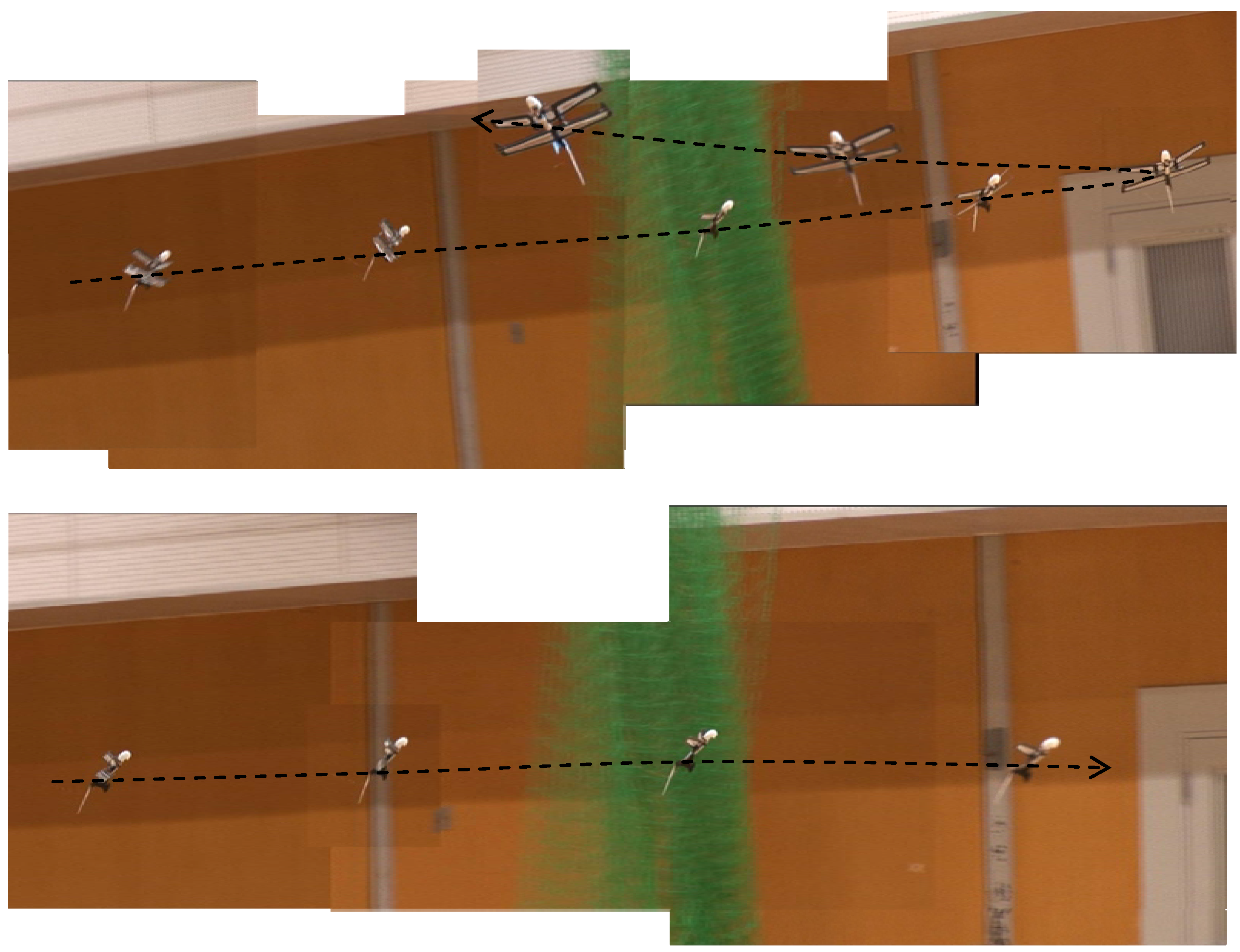
The dragonfly-shaped robot with this delta winglet was able to achieve controlled flight at an angle of attack of 40°.
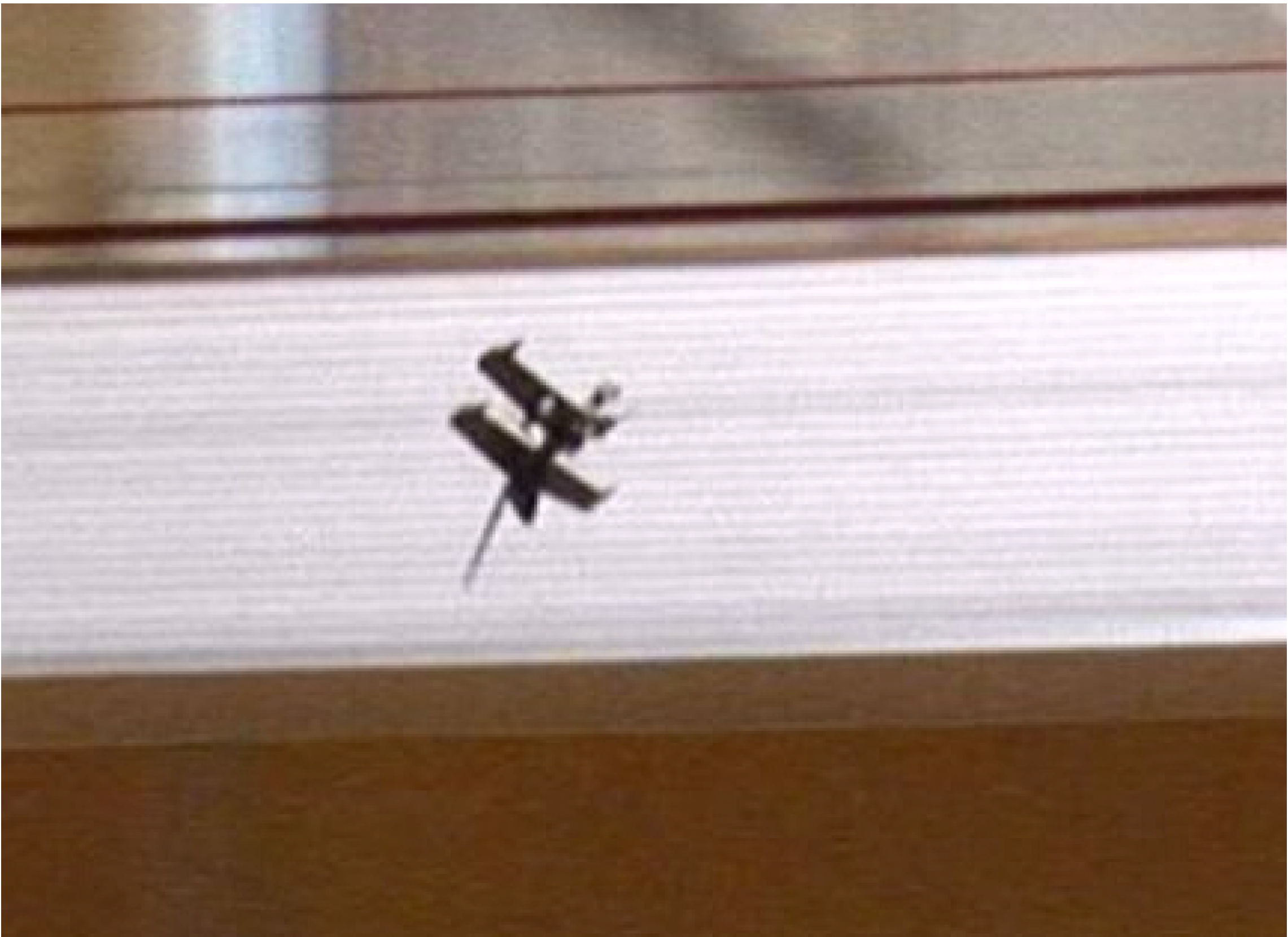
Figure 18 shows the robot turning at high angles of attack.
Figure 18.
Controlled flight of dragonfly shaped robot in the gymnasium (angle of attack is 40°).
Figure 18.
Controlled flight of dragonfly shaped robot in the gymnasium (angle of attack is 40°).
It is worthwhile to note that the rectangular plan formed dragonfly wings accept these simple high lift devices with minimum loss of weight or performance.
This image was made in the same way as that shown in
Figure 14. As would be expected, partial stalling was unavoidable and rocking behavior was exhibited, but total loss of control did not occur. The flight speed at this attack configuration as obtained by a speed gun was 2.2 m/s, meaning the dragonfly shaped flying robot was able to operate with normal controllability up to a lift coefficient (
CL) of 3.6 for the whole airplane.
The fact that the aircraft, which has a relatively large aspect ratio, attains a high
CL such as 3.6, suggests that dragonfly gliding mimetics has great potential. Not only is the dragonfly robot capable of flight at high angles of attack, but it also allows us to select a wide range of
CL which can be used to extend the flight time. The maximum flight time of fixed wing aircraft is greatest when
![Robotics 03 00163 i001]()
is maximized (where
CD is drag coefficient), which clearly requires the highest possible value of
CL. The main drive system was cannibalized from a toy aircraft of the same size, with which one of the developed dragonfly robots, in which the weight was 23 g, attained a flight time of 13 min and 30 s, although the original toy aircraft’s maximum flight time was around 10 min as written in the manual. In this flight, the flight speed was 5 m/s, and
CL was calculated to be 1.5, a result not easily achieved by conventionally configured aircraft in which it is difficult to install a stall prevention system.
It is noteworthy that the dragonfly-shaped robot has good compatibility with artificial devices, such as propellers and delta winglets. For example, the dragonfly robot did not lose altitude even when entering a forewing stall, since the propwash always flows over some area of the hind wings, meaning the hind wings never enter a full stall. Thus, if a forewing-stall does occur, the continuing hind wing lift produces a nose down pitching movement, allowing quick recovery and little loss of altitude. This is extremely valuable in outdoor flight because weak turbulence causes high angles of attack for low speed flying objects. These merits are considered to be achieved by the configuration of rectangular wings in a tandem arrangement.
A summary of the superiorities of the dragonfly flying robot is given below. Controlled flight over the track and field when the wind speed was less than 4 m/s was possible. Even with a wind speed of 6 m/s, it was possible to hover like a kite for at least 3 s if the wind flow was uniform. As will be explained later, we found that a cruciform configuration in which the forewings have a dihedral angle and the hind wings have an anhedral angle is the most resistant to rolling into sideslip. This configuration also shows considerably good flight characteristics and does not easily lose altitude in turns or with side-on wind, making it suitable for low-level flying. This configuration does not require a large fin installed in the middle of the body to stabilize the robot, a feature that was previously considered necessary to maintain controllability at high angles of attack.
This cruciform dragonfly robot has now become the standard for gliding mimetics in MFRL.


 is maximized (where CD is drag coefficient), which clearly requires the highest possible value of CL. The main drive system was cannibalized from a toy aircraft of the same size, with which one of the developed dragonfly robots, in which the weight was 23 g, attained a flight time of 13 min and 30 s, although the original toy aircraft’s maximum flight time was around 10 min as written in the manual. In this flight, the flight speed was 5 m/s, and CL was calculated to be 1.5, a result not easily achieved by conventionally configured aircraft in which it is difficult to install a stall prevention system.

