Article

Deployment Environment for a Swarm of Heterogeneous Robots

Interdisciplinary Robotics, Intelligent Sensing and Control (RISC) Laboratory, School of Engineering, University of Bridgeport, Bridgeport, CT 06604, USA
*
Author to whom correspondence should be addressed.
Robotics 2016, 5(4), 22; https://doi.org/10.3390/robotics5040022
Submission received: 8 June 2016 / Revised: 10 September 2016 / Accepted: 26 September 2016 / Published: 26 October 2016

Abstract

:
The objective of this work is to develop a framework that can deploy and provide coordination between multiple heterogeneous agents when a swarm robotic system adopts a decentralized approach; each robot evaluates its relative rank among the other robots in terms of travel distance and cost to the goal. Accordingly, robots are allocated to the sub-tasks for which they have the highest rank (utility). This paper provides an analysis of existing swarm control environments and proposes a software environment that facilitates a rapid deployment of multiple robotic agents. The framework (UBSwarm) exploits our utility-based task allocation algorithm. UBSwarm configures these robots and assigns the group of robots a particular task from a set of available tasks. Two major tasks have been introduced that show the performance of a robotic group. This robotic group is composed of heterogeneous agents. In the results, a premature example that has prior knowledge about the experiment shows whether or not the robots are able to accomplish the task.

1. Introduction

Cooperative multi-agent robotic systems have been shown to be fault-tolerant in that a robot can take over the task of a failing one. It has been proven that a single robot with multiple capabilities cannot necessarily complete an intended job using the same time and cost as multiple robotic agents. Different robots, each with its own configuration, are more flexible, robust, and cost-effective. Moreover, the desired tasks may be too complex for one single robot, whereas they can be effectively done by multiple robots [1,2,3]. Modular robotic systems have been shown to be robust and flexible in the tasks of localization and surveillance [4,5], and reconnaissance [6]. Such properties are likely to become increasingly important in real-world robotics applications.
Decentralization means that the algorithm does not require access to the full global state and all control computations are done locally. However, to command large groups of robots, it is also essential to include an element of centralization to allow humans to interact and task the team. Our paper is based on the premise that there is a lack of software packages that provide control for the different platforms of robots individually and allow concurrent control of heterogeneous robotic teams. Our objective is to develop algorithms that can provide coordination between heterogeneous agents, besides building central software to track these agents. Such system design is motivated by our interest in multi-robot control for the deployment of potentially large numbers of cooperating robots with applications such as persistent navigation, localization, mapping, and object transportation.
In the following section we provide a short analysis of existing swarm deployment environments. In Section 3 we present a deployment software package for obtaining decentralized control that can provide interesting collective behaviors dedicated to different tasks/applications with a new collective and mobile reconfigurable robotic system. We do not consider the particular hardware or infrastructure of each swarm agent, as our focus is on building control mechanisms that allow the system to operate several simple heterogeneous agents. In Section 4 we evaluate the proposed software framework in simultaneous localization and mapping (SLAM) and human rescue applications. Finally, Section 5 presents a summary of the work and draws some conclusions.

2. Related Work

A comprehensive investigation and evaluation of the present multi-robotic systems (MRS) has been thoroughly discussed in our previous work [7]. In that survey we organized and classified 10 swarm robotics systems and their corresponding behavioral algorithms into a preliminary taxonomy. We concluded that several algorithms have been developed to run on swarms of robots. These algorithms varied in complexity. Some provided basic functionality, such as leader following, while others exhibited complex interactions between the team of robots such as bidding on tasks according to arbitrary rules. Many early approaches in the literature concentrated on behavior-based techniques, wherein several desired behaviors are prescribed for each agent and the final control is derived by weighing the relative importance of each behavior. On the other hand, recently researchers have begun to take a system controls perspective and analyze the stability of multiple robot agents. Other important hardware aspects of the current modular swarm robotic systems such as self-reconfigurability, self-replication, self-assembly, cost and miniaturization with robustness, flexibility, and scalability were thoroughly analyzed in our other work [8].
In robotic control environments, a graphical application software such as MobileEyes [9] and the C++ based software URBI [10] are available as open source systems. URBI provides GUI (Graphical User Interface) packages that aim to make a compatible code for different robots, and simplify the process of writing programs and behaviors for these robots. URBI works by incorporating sensor data to initiate commands to the robot. URBI packages, however, provide no abstractions. Therefore, they do not allow for separating the controlling system from the rest of the system. For example, a control system might be intimately tied to a particular type of robot and laser scanner.
The Player/Stage proposed by Gerkey et al. [11] also produces tools for simulating the behavior of robots without actual access to the robots’ hardware and environment. Its two main products are the Player robot server, a networked interface to a collection of hardware device drivers, and Stage, a graphical, two-dimensional device simulator. The player/Stage is basically designed to support research in multi-robot systems through the use of socket-based communication. The player/Stage is an open-source software that is available to be downloaded online on UNIX-like platforms. However, running this software requires a variety of prerequisite libraries and each library requires another set of libraries. It has never been easy to understand how the system communicates with the actual robots. Player/Stage mainly supported robotic platforms such as RWI/iRobot, Segway, Acroname, Botrics, and K-Team robots.
Nebot et al. were more interested in developing cooperative tasks among teams of robots [12]. Their proposed architecture allowed teams of robots to accomplish tasks determined by end users. A Java-based multi-agent development system was chosen to develop their proposed platform. Zhang et al. [13] proposed a software platform comprised of a central distributed architecture that runs in a network environment. Their system is composed of four parts, namely a user interface, a controlling center, a robot agent, and an operating ambient making up the platform top-down.
Another script-based robot program is Pyro [14]. Pyro, short for Python Robotics, is a robotics programming environment written in the Python programming language. Programming robot behaviors in Pyro is accomplished by programming high-level general-purpose programs. Pyro provides abstractions for low-level robot specific features, much like the abstractions provided in high-level languages. The abstractions provided by Pyro allow robot control programs written for small robots to be used to control much larger robots without any modifications to the controller. This represents an advancement over previous robot programming methodologies in which robot programs were written for specific motor controllers, sensors, communications protocols, and other low-level features. Kulis et al. [15] proposed a software framework for controlling multiple robot agents by creating a Distributed Control Framework (DCF). DCF is an agent-based software architecture that is entirely written in Java and can be deployed on any computing architecture that supports the Java Virtual Machine. DCF is specifically designed to control interacting heterogeneous agents. DCF uses a high-level platform-independent programming language for hybrid control called MDLE (Motion Description Language Extended).
Elkady et al. [16] have developed a framework that utilizes and configures modular robotic systems with different task descriptions. Their main focus was designing a middleware that is customized to work with different robotic platforms through a plug-and-play feature that allows for automatic detection and auto-reconfiguration of the attached standardized components installed on each robot according to the current system configurations. Therefore, the authors’ solution is to deal with the abstraction layers residing between the operating system rather than software applications. A similar system hierarchy is used in Mobile-R [17], where the system is capable of interacting with multiple robots using Mobile-C library [18], an IEEE Foundation for physical agents’ standard compliant mobile agent systems. Mobile-R provides deployment of a network of robots with offline and online dynamic task allocation. The control strategy structure and all sub-components are dynamically modified at run-time. Mobile-R provides some packages to enhance system capabilities like artificial neural networks (ANNs), genetic algorithms (GAs), vision processing, and distributed computing. The system was validated through a real world experiment involving a K-Team Khepera III mobile robot and two virtual robots simulated using the Player/Stage system.
Gregory et al. [19] proposed an application software built in JAVA to operate heterogeneous multi-agent robots for the sake of educational purposes named MAJIC (Multi-Agent Java Interface Controller). The system provides basic components for user interaction that enable the user to add/remove robots change the robotic swarm configuration, load Java scripts into robots, and so on.
In ASyMTRe-D [20], the authors’ approach is based on schemas such as perceptual and motor schemas. Inputs/outputs of each schema create what it is called semantic information that is used to generate coalitions. Tasks are assigned to the robot with the highest bid. Bids are calculated according to the costs of performing different tasks. A set of tasks is allocated to coalitions. Coalition values are calculated based on the task requirement and robot capabilities. Execution of tasks is monitored and the process of allocation repeats itself until each individual task is completed. During run-time their novel protocol ASyMTRe-D is executed. This protocol manipulates calculated coalition values to assist in completing tasks. Authors do not mention the dynamical tasks and ways of task reassignment. Additionally, they do not discuss fault tolerance, flexibility, robustness, and how the system reacts to any robot failure.
In the Symprion/Replicator project [21], what determines the behavior of an agent or group of agents is the HDRC (Hormone Driven Robot Controller), which contains a configuration for the robot itself, and a software controller called Genome that runs a utility-based allocation algorithm. Frontier-based task allocation, such as in MinPos [22], is another approach to the frontier allocation problem and is based on the distribution of robots among the frontiers.

3. Methodology

We developed an environment to utilize robots that have different modular design and configuration of sensory modules and actuators. The system will be implemented as a GUI interface to reduce efforts in controlling swarm robotic systems. The proposed application offers customization for robotic platforms by simply defining the available sensing devices, actuation devices, and required tasks. A task is a general mission assigned to a group of robots instead of one (e.g., painting a wall). The main purpose for designing this framework is to reduce the time and complexity of the development of robotic software and maintenance costs, and to improve code and component reusability. Usage of the proposed framework obviates the need to redesign or rewrite algorithms or applications when there is a change in the robot’s platform or operating systems, or the introduction of new functionalities.
UBSwarm environment is a high-end interface used for distributing algorithms to heterogeneous robotic agents. One of the key features of UBSwarm is configuring special programs that act as middleware to gain control over the agent’s parameters and devices. The middleware consequently allows auto-detection of the attached standardized components according to current system configurations. These components can be dynamically available or unavailable. Dynamic detection provides the facility to modify the robot during its execution and can be used to apply patches and updates, to implement adaptive systems. This real-time reconfiguration of devices attached to different robots and driver software makes it easier and more efficient for end users to add and use new sensors and software applications. In addition, the high-end interface should be written in a flexible way to get better usage of the hardware resource. Also, they should be easy to install/uninstall. The basic hierarchy of the UBSwarm deployment platform is shown in Figure 1.
Another key feature of the UBSwarm interface is to move the communication implementation from the user’s domain to the application domain. Instead of learning proprietary protocols for individual robots, the user can utilize the UBSwarm scripting language to pass common commands to any robot managed by the application. UBSwarm adds a layer of abstraction to such tasks, allowing users the ability to intuitively obtain desired responses without extensive knowledge of robot-specific operating systems and protocols. When users make changes to the hardware devices that are plugged onto the robotic agent, UBSwarm will provide the appropriate software package for these sensory devices and actuators. This flexibility makes it easy for end users to add and use the new devices and consequently task applications. In addition, the software code can be written in the most common programming languages such as Python, C++, or any language that is specific to a particular robot framework. These Software components are easy to install/upload in the console screen. At startup, UBSwarm uploads a code that is responsible for scanning for hardware changes onboard because almost all microcontrollers include a hardware feature to interrupt the current software routine and run a scanning routine when a particular pin (PINS are the I/O ports found on the microcontroller board) changes state. By relying on the hardware to notice a change, we can keep track of hardware components. Each one of these hardware components is operated using a particular algorithm that is created at the time of deployment. UBSwarm runs on a computer and uploads programs to or communicates with/monitors the robots through the USB (serial port), RF, WiFi, or Bluetooth. In our experiment we used our own robot agents that incorporate Arduino and Digilent Max32 microcontrollers.
UBSwarm provides a direct forward two-step configuration that helps the operator to select between several available robot computers (microcontrollers) actuators, and sensors and then assign the group of robots a particular task from the set of available tasks. To test and evaluate the swarm system or to change the configuration of the whole system, the user should be able to change each robot’s features. That is, the user has the option to add/remove hardware features of any selected robot. The user can also decide which robots should be assigned for the task. In the main menu, the user is given a list of tasks to be assigned to the swarm system.

4. System Architecture

UBSwarm is an interactive Java-based application designed for extensibility and platform independence. The system establishes communications with embedded robot modules via various mediums. At the time of startup the system will expect the operator to:
-
Configure the system by picking the available agents, their onboard features (sensors, motors, etc.), and the services needed to accomplish each task
-
Run the system using saved configurations and add/remove agents.
The system is divided into two main subsystems, a robot deployment system and a robot control and translation system. The robot control system includes a robot control agent in which the user should provide all the parameters required for all sensors incorporated on robots. The user should also describe the actuation methods used. The robot deployment system encapsulates a variety of high-level applications in a module that contains the tasks to perform such as navigation, area scanning, and obstacle avoidance. A hardware abstraction layer is used to hide the heterogeneity of lower hardware devices and provide a component interface for the upper layers.

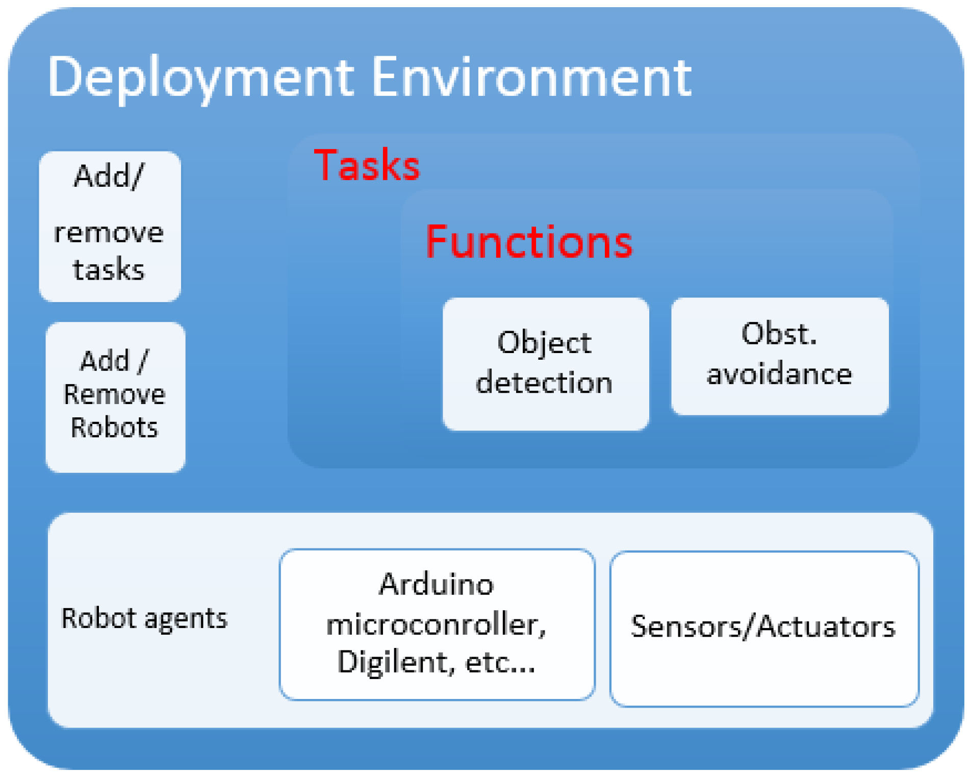
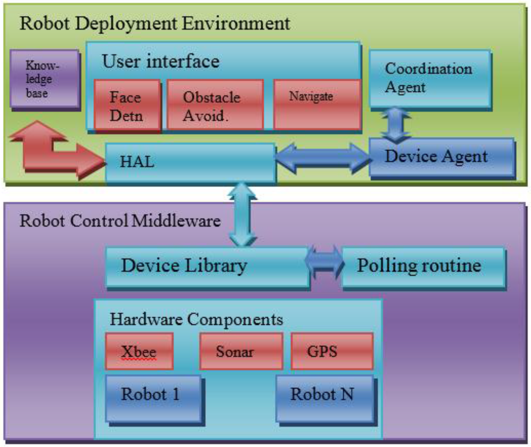
4.1. Robot Deployment Environment

The deployment system interacts with agents through various types of communications protocols. The deployment system takes responsibility for running actions according to the definition parameters and the different integrations of the heterogeneous robots. Each application is implemented as a software module to perform a number of specific tasks used for sensing, decision-making, and autonomous action. Actions are platform-independent robot algorithms; for example, they can be an obstacle avoidance algorithm or a data processing algorithm using Kalman’s filter, etc. These actions can communicate using message channels. The deployment system framework is shown in Figure 2. The deployment system contains the developer interface, the coordination agent, the dynamic interpreter, and the knowledge base.

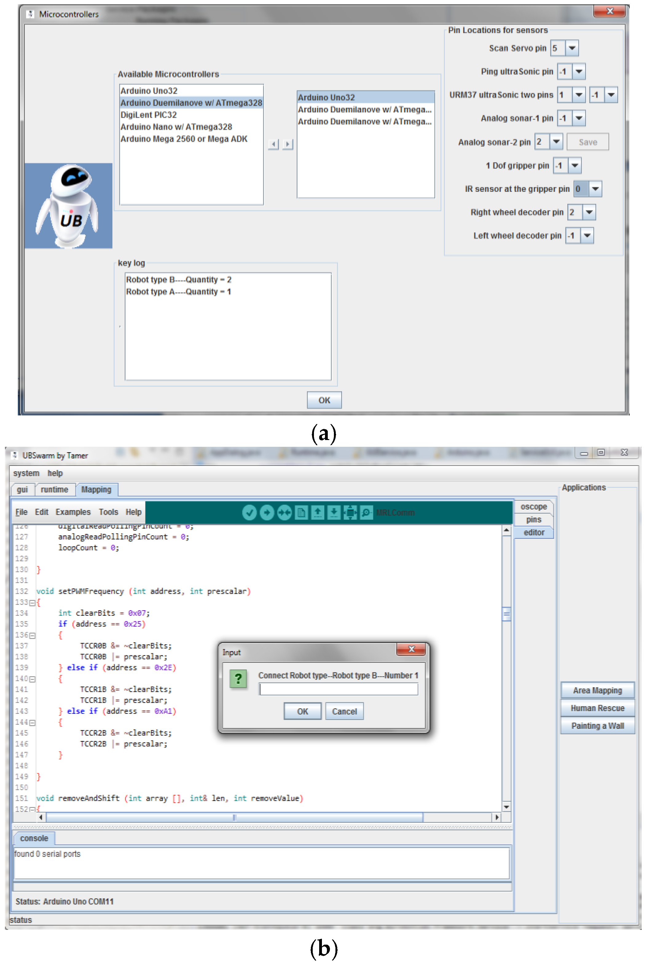
4.1.1. User Interface

The system developer interface provides the human operator command and control windows. The user can interact with the computer through interaction tools that provide a list of actions/tasks and available robotic agents. In some other parts of the interface, the user will be prompted to input the required system parameters for all sensors incorporated on robots such as the PIN numbers to which each of the sensor/actuator is connected. As mentioned earlier, UBSwarm connects to the robots using a USB cable, RF, WiFi, or Bluetooth. The user has to provide the IP address of the particular robot when WiFi is used. When connecting the robot to the USB, UBSwarm will detect the COM port automatically. After defining all required parameters, the user will have the chance to write programs and upload them on each robot. The interface provides a number of tasks that can be assigned to the group of robots such as SLAM, and human rescue (pulling an object). Each task is defined as a functional module. Obstacle avoidance, navigation, and SLAM are examples of such functional modules. Each functional module encapsulates services such as Opencv, Hough transformation, etc. Each service is regarded as a component of the system and is described in an XML configuration file to remove platform dependency.
The user interface also allows users to update, remove, or add robots in the swarm group. The programs that will be uploaded on each robot type differ according to the different pin locations associated with each type that were set by the user. The system will ask the user to connect each robot to allow for uploading the program, as shown in Figure 3b. The next four subsystems show how the deployment system works to manage the heterogeneity of the hardware and the software associated with each robotic agent.

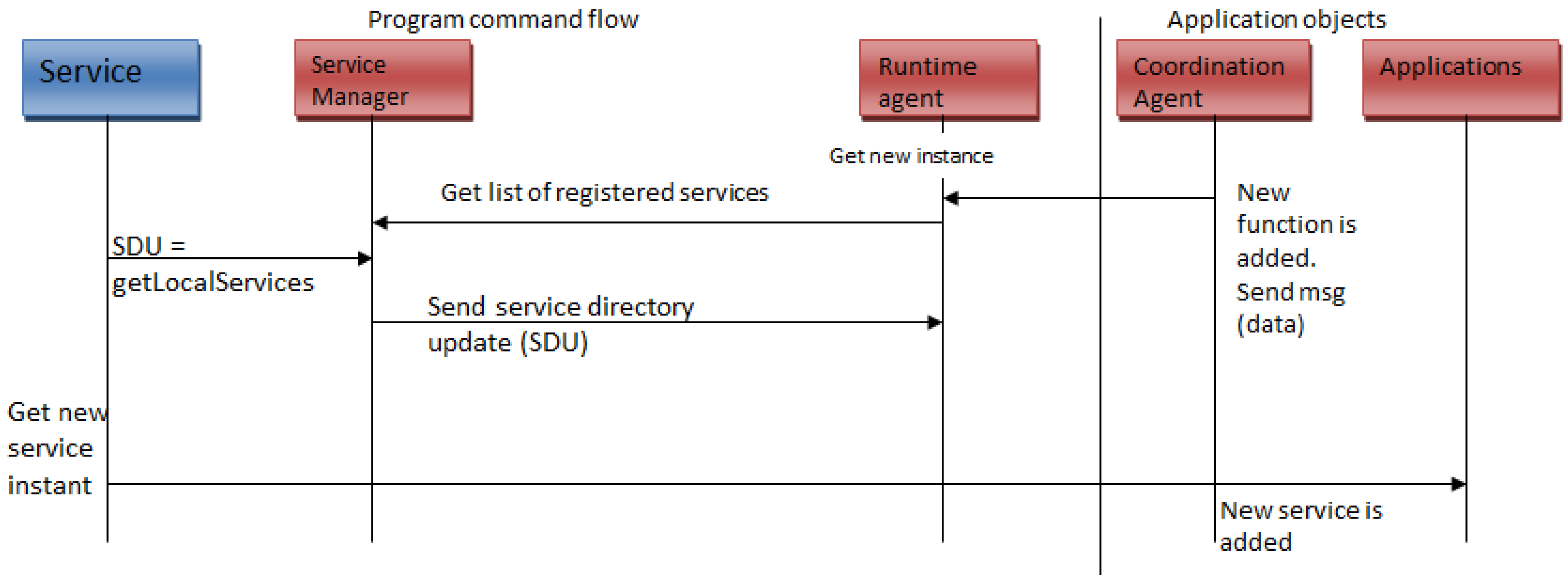
4.1.2. Coordination Agent

The heterogeneity of the robots and the operating platforms imposes dependencies such as the data format, location of machine addresses, and availability of the components. As addressed in [16], the data format dependency is removed by a standard data format that is machine-independent. Just like the functional modules described earlier, the data format is regarded as a component in the system. Relevant tasks for a team mission are defined by the XML configuration file that is loaded at startup. The XML file also specifies which tasks can be performed by each agent. The coordination manager is responsible for optimal assignment problem (OAP), which uses the Utility concept found in game theory [23]. We proposed a solution called Robot Utility-based Task Assignment (RUTA) in our previous work [24]. The RUTA algorithm is based on the following assumptions:
-
T is the task to be accomplished, which is a set of m subtasks that are basically composed of motor, sensor, and communication devices that need to be activated in certain ways in order to accomplish this task. It is denoted as T i = { v i 1 , v i 2 , v i 3 , , v i m } , where v i j is the subtask j performed by robot r i and 1 i n , 1 j m .
-
A subset v i j of T i can be allocated to robots concurrently if they do not have ordering constraints.
-
To accomplish the task T i on robot r i , a collection of n plans (solutions), denoted Pi = { P 1 , P 2 , …, P n }, needs to be generated based on the task requirements and the robot capabilities.
We define a cost function for each robot, specifying the cost of the robot performing a given task, and then estimate the cost of a plan performing the given task. We consider two types of cost:
-
A robot-specific cost determines the robot’s particular cost (e.g., in terms of energy consumption or computational requirements) of using particular capabilities on the robot r i to accomplish a task v i j (such as a camera or a sonar sensor). We denote robot r i s cost by robot cost ( r i , v i j ).
-
The cost of a plan Pi performing a task T i is the sum of the individual cost of robot i performing sub-tasks m that are in the plan P i , which is denoted by: C o s t ( P i , T i ) = j = 1 m cost ( r i ,   v i j ) where 1 i n .
Given (T, R), we define a solution Pi to each task T i such that C o s t ( P i ,   T i ) is minimized. We assume that sub-tasks v i j allocated to robot r i must be ordered into a schedule σ i = ( v i 1 ,   t 1 ,   t 1 ) ,   ,   ( v i j ,   t j ,   t j ) for 1 j m where v i j is the subtask performed from time t j   t o   t j . Each sub-task assigned to a robot is denoted by a triple, α j t y p e ,   t e j ,   r a t e j > representing the v i j task type whether, sensing or actuation, the time assigned to the task until it is accomplished (so t s j = t j t j ), and the consumption rate (in mA) for this particular subtask respectively. Depending on the robot r i s location, the time spent on each task must equal r i s assigned share of the workload. We also assume that the distance in meters between robot r i to subtask v i j is d i j . Taking these values into account, each robot can be represented as β i i d ,   w i ,   P r e m i > , representing the robot’s identification number, w i is the percentage of the robot i wheel slip, and P r e m i is the power remaining for the robot. The cost of a robot r i performing a subtask v i j is calculated by dividing the robot r i ’s remaining battery power by the product of multiplying the sensor and/or actuator consumption rate by the percentage of time in which it is operating. This is determined by the following equations:
φ m a n i p   i j = 0.7 × [ ( t s j t m ) [ P r e m i r a t e a c t   j ] ]
φ n a v   i j = 0.7 × [ [ p r e m i r a t e s e r v o   j ] × 1 w i ]
φ s e n s   i j = 0.9 × [ ( t s j t m ) [ P r e m i r a t e s e n s   j ] ]
φ g i v e n   i j = φ m a n i p   i j + φ n a v   i j + φ s e n s   i j ,
where t m is the total time predetermined for the robot r i to complete all of its subtasks in seconds, w i is the pre-assumed percentage of robot r i wheel slip, and φ m a n i p   i j , φ n a v   i j , and φ s e n s   i j are the qualities to perform manipulating, navigation, and sensing subtasks, respectively. Depending on the subtask type, the value of any of these quality functions is null if they are not taking place in the subtask. φ g e v i n   i j is the total quality of subtask v i j being performed by robot r i . When an obstacle avoidance task is being performed, the quality function φ g i v e n   i j has higher values than the other qualities because it includes navigation as well as sensing subtasks. The priorities of subtasks must be considered and are calculated according to the schedule of tasks σ i set for robot r i . The priority of robot r i performing a subtask v i j is defined by the following equation, with the priority bounded between 0 and 1:
p r i i j = 1 2 × min [ ( u 1 × ( t t j ) ) , 1 ] ,
where t is the current time elapsed since the beginning of the task and t j is the time when the task is announced as declared in the schedule σ i . The parameter u 1 adjusts how the priority should increase with the value of ( t t j ) . The assignment of a subtask v i j to the specific robot (that is capable of accomplishing it) is determined by the Utility function of a robot r i performing a task v i j , as in the following equation:
u t i l i t y i j = max ( 0 ,   u 2 × ( d i j 1 / 2 × φ g i v e n   i j × p r i i j ) ) ,
where u t i l i t y i j is the nonnegative utility of robot r i for sub-task v i j , 1 ≤ in, 1 ≤ jm, and u 2 is the weighted coefficient to adjust the effect of the variables inside the equation. d i j is the distance in meters between robot r i to subtask v i j . The smaller the distance d i j is, the higher the u t i l i t y i j , thus we notice that a robot closer to the goal has a higher utility. That is only true for the subtasks that are related to the location of the robot, e.g., in a human rescue task, the robot already nearer to the body has an advantage that should affect its utility value. Whereas, in the other subtasks, when no distance is involved, d i j has a value of 1.
Robots are added randomly. No particular time is set. The decision to involve a robot in a task depends on its utility value. The robots are of different types. A summary of the two modes is as follows (found in our previous work [24]. As the task is being executed, the following two algorithms take place. The optimal number of robots is decided by running the following algorithm (Algorithm 1), which equals the final value of i.
Algorithm 1. Input: (T, R, M, N)
1.
For each unexecuted sub-task v j in the schedule
2.
For each robot r i in the new robot ordering
3.
{Calculate Utility function u t i l i t y i j for robot r i
4.
If the current utility of r i for sub-task v j is greater than its previous utility then assign subtask v j to r i based on the task requirements
5.
    →Add ( r i , v j ) to plan Pi
6.
    →Update parameters in v j
7.
Stop when the task is completed or after K number of trials
8.
Go to step 10 if a faulty robot is discovered
9.
  }
10.
If task is not complete, pick the robot with the highest utility value from the list of remaining robots
11.
→Add to robots ordering
12.
Go to Step 1
In the distributed approach, decentralized coordinated programs are uploaded on the swarm of robots at startup. The programs allow the set of robots to reason, reassign, and execute subtasks later during their mission should a failure or a change in the swarm team be introduced. During run-time, each robot simply calculates its own utility when tasks are taking place, as shown in Algorithm 2. Information about robot status (such as any error readings from sensors) is shared between robots. If the task is interrupted or a failure is introduced to the swarm team, robots are able to reconfigure new task solutions to cope with changes in team composition and task requirements.
Algorithm 2. Input (R, N)
1.
Utility is calculated on each robot
2.
The two robots with the highest utility values will begin their pre-programmed plans
3.
While task is not complete
4.
{
5.
Each robot’s utility value is shared with the other robots. When a robot is introduced to the system or if a sensor fails on one robot r i by which it is prevented from completing task v j , it sends a request (bid) to the other robots in the team.
6.
Robot waits for reply ( t o u t ) from the fittest one (based on the highest utility value).
7.
Task v j is taken over by the winning robot.
8.
}
9.
Stop if task is complete; else call the next robot in the ordering R

4.1.3. Runtime Interpreter

When new devices are plugged in, system developers can install new platform software packages specific to the execution of the newly added devices. In other words, system developers can extend the system’s functionality by adding new service modules (i.e., program functions such as obstacle avoidance) to the list of available modules that can be found under the “runtime” tab in the main menu. When a new service is added to the system, the dynamic interpreter manages the flow of information between these services by monitoring the creation and removal of all services and the associated static registries. The runtime interpreter maintains state information regarding possible and running local services. The host and registry maps are used in routing communication to the appropriate tasks. The flow of information managed by the dynamic interpreter is shown in Figure 4. The dynamic interpreter will be the first service created, which, in turn, will wrap the real JVM Runtime objects.
When new services are added to the system, messages will be initiated by the runtime interpreter. The message consists of two basic parts: the header (which describes the data being transmitted, its origin, its data type, and so on) and the body (data). There are four types of messages, the Command message, used to invoke a service in another application; the Document message, used to pass a set of data to another application; the Event message, used to notify another application of a change in this application; and the Request-Reply message, used when an application should send back a reply. The messages are classified into three categories: Simple message (small messages with low delay requirements), real-time message (small message with a certain deadline), and message stream (message sequence with a certain rate). The priority setting of a message can be adjusted so that an urgent message should be delivered first. Figure 4 shows the operation of the runtime interpreter when services are added to the system.
Once the coordination agent completes its job, the dynamic agent breaks down allocated tasks into required actions from actuator movements to communications. Then, the dynamic interpreter monitors the flow of data, manages the flow of messages through the system, makes sure that all applications and components are available, tracks the quality of service (e.g., response times) of an external service, and reports error conditions. The dynamic interpreter does its job by utilizing a component requirement matrix for each robot. The component requirement matrix is used to combine the necessary components from the knowledge base to the mobile agents, which are then passed to the robot control and translation agent. As described in [16], each component has an XML configuration file to customize its behavior. Each component is designed to be dynamically reconfigurable by the dynamic interpreter during robot operation.

4.1.4. Knowledge Base (Registry)

The knowledge base contains all of the necessary information for each robot to give the operator the ability to address each task. This includes a listing of all possible actions, service modules, and behavioral component implementations for each robot. The knowledge base stores service types, dependencies, categories, and other relevant information regarding service creation. It also includes the agents’ required communication protocols, and their drivers. Physical and logical addresses associated with each component are also stored in the knowledge base.

4.2. Robot Control Middleware

From a programming prospective, the robotic agent is a class. This class specifies the methods that must be provided by implementing such class. The class interface architecture enables a loose coupling between the control algorithms and the underlying hardware; alternative hardware sensors supporting the required sensing functionalities may be interchanged freely (tested in the experiment). Unlike some robot agents that contain a regular PC as part of their systems, our swarm system is composed of robotic agents that incorporate onboard microcontrollers. UBSwarm supports most of the Arduino and Digilent PIC microcontrollers. Each robot has TX/RX pins that use the microcontrollers’ serial communication and turn it into IO-slave. Each robot agent incorporates two software programs to perform its job.

4.2.1. Device Library

The device module contains information to be uploaded to the XML file about the hardware components, which are classified according to the functionalities they provide. For example, a GPS receiver can function either as a position device or as a range device. The device module gets a single input from the GUI operator interface; this input is the type of the microcontroller board connected. Based on the type of the board, the device module will have the information it needs about the microcontroller and the I/O ports. The Arduino microcontroller boards have a PIN arrangement as follows:
-
Serial: 0 (RX) and 1 (TX). Used to receive (RX) and transmit (TX) TTL serial data. For example, on the Arduino Diecimila, these PINs are connected to the corresponding pins of the FTDI USB-to-TTL Serial chip.
-
External Interrupts (PINs 2 and 3): These pins can be configured to trigger an interrupt on a low value, a rising or falling edge, or a change in value.
-
PWM (Pulse Width Modulation) Pins: 4 up to 24 provide 8-bit PWM output.
-
Analog Pins: PINs 25 and higher (analog input pins) support 10-bit analog-to-digital conversion (ADC).
Relevant tasks for a team mission are defined in the device module configuration file, which is loaded by the UBSwarm at startup. The device module file also specifies which tasks can be performed by each agent and, if applicable, the physical hardware sensors and devices to be used.

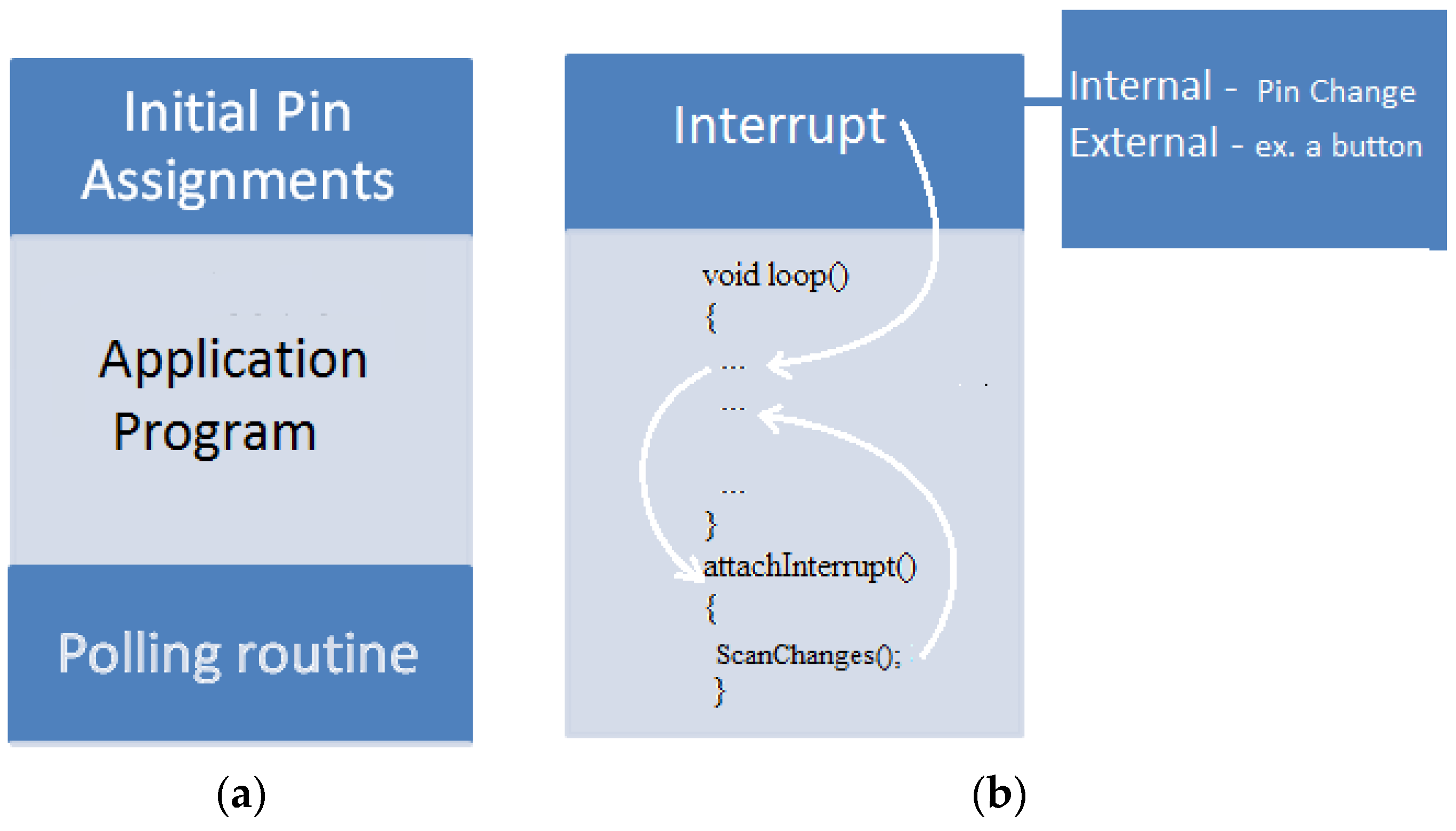
4.2.2. Controlling Program

The program that is uploaded on each robot agent consists of the task-related controlling code, the initial pin assignments, and a polling routine, as shown in Figure 5a. This program contains function blocks to operate all the current hardware components that are currently connected and all possible functions associated with each new component that might be attached to the robot. The controlling program has conditional statements to decide which function to call. The decision of which blocks of code to run depends on the updated pin assignments after the execution of the polling routine and the task intended from the robot. The polling routine is executed only if an internal interrupt has been activated.

4.2.3. Polling Routine

The polling routine is basically the hardware tracker/scanner of the robotic agent. It is a piece of code that resizes in the microcontroller; its job includes continuously receiving raw data from onboard sensors. When an external interrupt is activated, the processor takes immediate notice, saves its execution state, runs the polling routine, and then returns to whatever it was doing before. Figure 5b shows the sequence of actions when an internal or external interrupt is triggered. The type of interrupt used is an external button connected to an interrupt pin and the ground (GND). When this pin changes its signal edge (from rising to falling or vice versa), the polling routine scans all the other signal pins for newly attached components. After gathering such data, the polling routine sends messages that include the state data about the hardware components attached to each I/O pins. These data also include the type of the sensor. In order for the polling routine to understand which kind of sensor has been connected, we divided the set of pins into two categories:
-
Digital PWM pins can only be connected to Ultrasonic sensors or servo motors
-
Analog pins can only be connected to Infra-red or sonar sensors
The robot agents also incorporate the following module, which provides essential input to the polling and controlling programs.

4.2.4. Hardware Abstraction Layer

The Hardware Abstraction Layer (HAL), the platform-dependent part of UBSwarm, is used to hide the heterogeneity of lower hardware devices and provide a component interface for the upper layers. HAL removes hardware and operating system dependencies between the robot and the application in order to assure the portability of the architecture and application programs. It provides access to the sensor data or actuation commands abstracted from the underlying physical connection of the resource. The standard interface to hardware devices takes place through the seven following operations (all the operations will indicate error conditions if they fail): Open, Close, Read, Write, Get attributes, Set attributes, and Lock. The abstraction layer shown in Figure 2 contains hardware-dependent control libraries that act as low-level middleware to hide the heterogeneity of the underlying microcontrollers.

5. Experimental Results
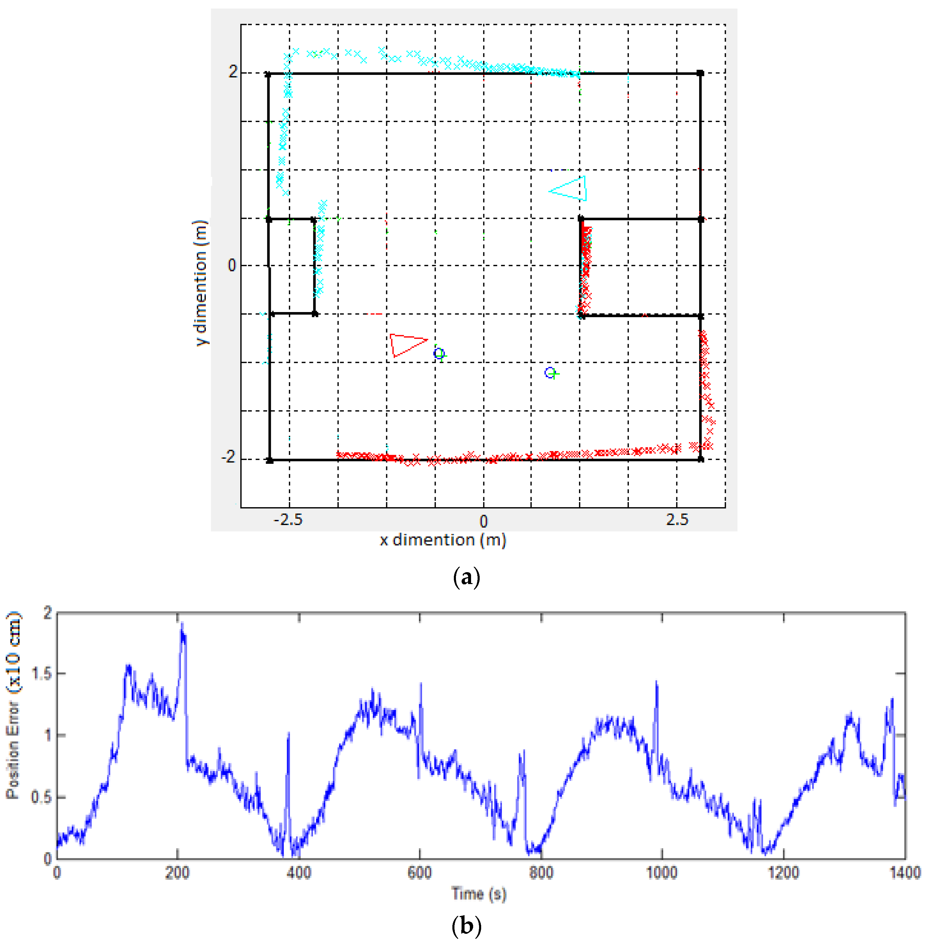
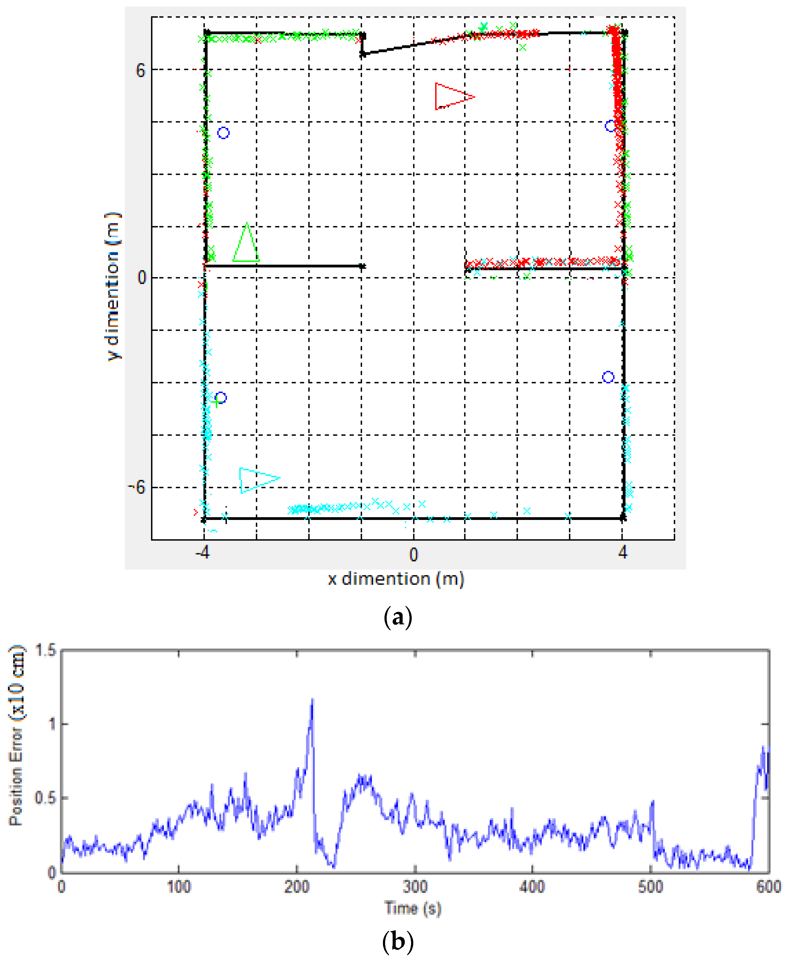
Our swarm system is composed of semi-intelligent heterogeneous robots. Hence, robots have very simple behaviors, but the overall high intelligence of the group is actually created by the simple acts and moderate local intelligence of each individual robot. Each robot’s behavior is determined by running different programs to cope with the changes in the overall swarm configuration. Each program contains parameters that will be assigned to the values that are initially set by the user when starting UBSwarm interface.
A complete discussion about the robotic agents used in our experiments can be found in [25]. The robotic platforms shown in Figure 6 are built using Arduino UNO, Arduino Due, and Digilent PIC boards. These boards are designed to make the process of using electronics in multidisciplinary projects more accessible. The hardware consists of a simple open hardware design and a rigid frame to support and secure the different types microcontroller boards and onboard input/output components. The software is uploaded on each robotic agent using UBSwarm interface running on a Windows operating system. As for power source, six packs of 6 V 2500 mAh Ni-MH batteries ensure sufficient energy autonomy to the robots. For distance sensing, a URM V3.2 and PING ultrasonic sensor were used. However, as experimental results depict, the sensing capabilities of the platforms can be easily upgraded with other sensors, e.g., laser range finders. Additionally, the platforms are also equipped with an Xbee Shield from Maxstream, consisting of a ZigBee communication module with an antenna attached on top of the Arduino Uno board as an expansion module. This Xbee Series 2 module is powered at 2 mW, having a range between 40 m and 120 m, for indoor and outdoor operation, respectively.

5.1. Mapping Task

One of the experiments we conducted is mapping. Mapping or SLAM is a technique used by robots to build up a map within an unknown environment (without a priori knowledge), or to update a map within a known environment (with a priori knowledge from a given map). Since our robots are equipped with simple hardware capabilities, the primary mapping technique will involve simple sonar and ultrasonic range finders to read distances as the mapping takes place. Each robot is placed on different corners of the building. Robots start scanning the surrounding area using an ultrasonic distance reader mounted on the top of each robot. Decoders on each robot’s wheels measure the distance the robot has covered as it scans. These two readings are combined with a third reading from sonar sensors mounted on each side of the robot to add more accuracy and redundancy to the scanning ability. All together, these readings will generate two-dimensional values that will be fed to a Matlab program on a base station, which in turn generates a 2D map of the scanned area. Each robot communicates with the base station using Wireless Xbee modules, which provide communication via Wireless WiFi. One Xbee module is attached to the base computer through USB port. As far as the Matlab program is concerned, the SLAM technique uses an Extended Kalman Filter (EKF) to predict measurements. The EKF receives estimates from each robot’s ultrasonic range finders, wheel odometry, and/or sonar readings. The user decides whether or not to use these sonar readings as he runs his/her tests against performance criteria.
We ran SLAM experiments on each robot group simultaneously, meaning a mapping program is uploaded on each robot in two experiments as follows:
-
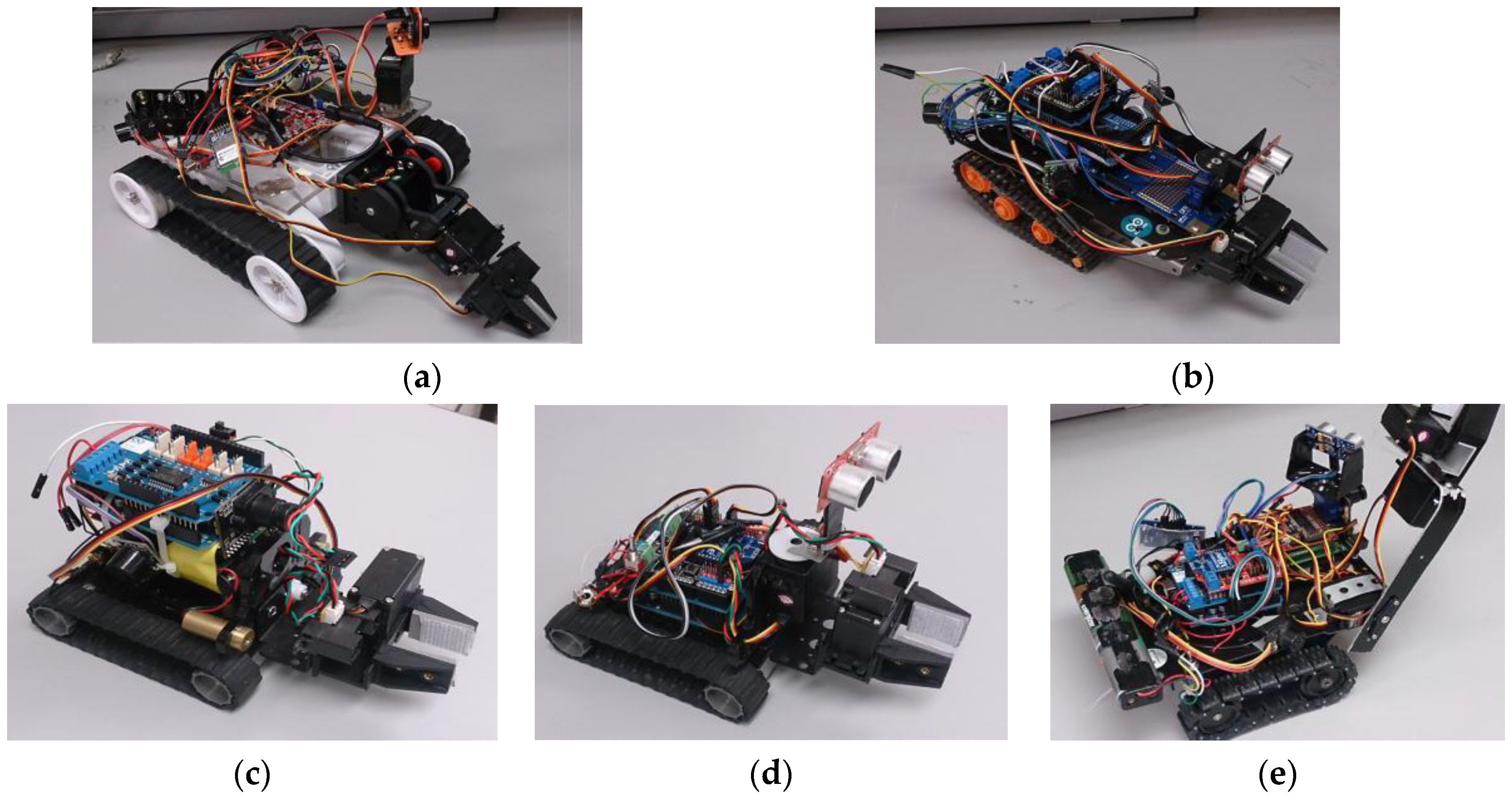
Experiment 1 uses two robots; each one has wheel encoders and one onboard ultrasonic range finder.
-
Experiment 2 uses three robots, each of which has the same configuration as the above robots plus two more sonar sensors mounted on the sides.
Hence, the first experiment deploys two robots with two sensing components, whereas three robots each equipped with three sensing components were deployed in the second experiment. In the first experiments, the mapping task took 23 min, whereas the second experiment took 10 min to complete. Figure 7a shows the actual map (black outline) and the estimated measurements (blue and red dots) generated by the two robots (blue and red triangles). As the mapping task proceeds, Figure 7b shows the error generated by the swarm of robots as opposed to the actual distance to the wall, objects, and so on. We can see that at some points the program receives extremely incorrect readings from the ultrasonic sensor. After analyzing the cause for this inconsistency, we found that a particular type of ultrasonic sensor reads a value of 0 and this was not the case with the other types of sensors. One solution to this hardware error is to repeat (placing in a loop) the reading/scanning command until it reads a non-zero value.
Figure 8a and b show results of the second experiment, when one more sensing component is added to each of the three robots (indicated by the red, green, and blue triangles). The average is taken between the two readings (on-board ultrasonic sensor and side sonar sensors). Such an addition will have the benefit of boosting the accuracy of the measurements as well as adding redundancy to the robotic system should any sensor fail when tasks are being executed. The average of the error generated by all of the robots is calculated and depicted in Figure 7b and Figure 8b. Please note the maximum error value in both figures.

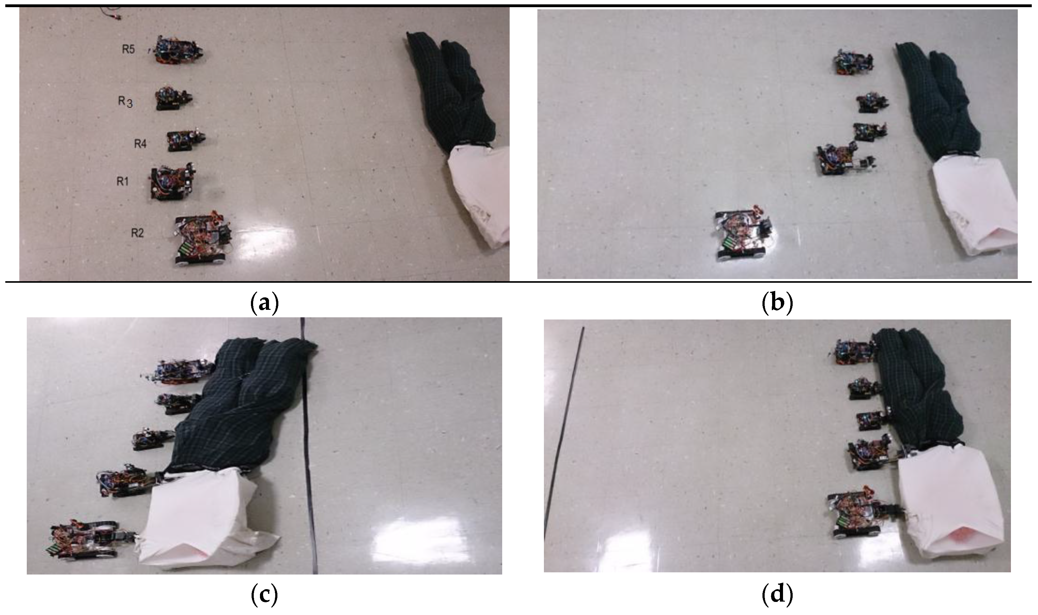
5.2. Human Rescue Task

The human rescue algorithm has been developed for UBSwarm so that robots can autonomously cooperate and coordinate their actions so that a human dummy can be pulled away in a minimal time. Centralized as well as decentralized approaches have been used in this task. Our previous work [24] provides a brief discussion of these approaches. Cooperation between robots is achieved by exchanging messages when an additional robot is needed to pull the object. First, the software environment deploys a particular type of robot that searches for a human dummy as it wanders in the unknown environment; such a robot is equipped with an onboard camera allowing it to detect a white stripe attached to the human body lying on the ground. Video frames are received at a base station computer. The frames are fed into the Matlab program, which detects the white stripe using a line detection module, as shown in Figure 9. The algorithm incorporates Hough transform and enhanced edge detection algorithms.
If more robots are needed to pull the object, the robot calls another agent using the Xbee-based communication module. Wheel encoders on each robot are used to decide whether or not to call more robots. When the pulling subtask is being performed by a robot, its wheel encoders read the elapsed distance. If the distance is zero, it calls for more agents to be sent. Robots place themselves at different locations. Using their grippers and by sending a special synchronization message, the robots attach themselves to the body and start pulling backward towards the goal position. A human prototype is built and several experiments were conducted. As the weight of the human increases, more robotic swarm agents were called. We noticed that the configuration that uses more than three robots is able to pull the object successfully. However, this configuration causes the robots to skid to the side. Consequently, this act increases the time taken by the robots to complete the task. Dispatching the right number of robots is the goal that is generated by the algorithm embedded in UBSwarm. As said earlier, centralized as well as decentralized coordination modes are adopted to perform three trials for each experiment set indicated by the number of robots. Data were obtained for the completion time and the number of successful experiments. In total, 24 trials were performed.
In the first experiment set, when four robots were used (R1, R3 and R5) in a centralized fashion, we triggered faulty sensors at time 100 s to illustrate the fault-recovering capabilities of the swarm team. In that experiment, R5 performs its assigned tasks according to the plan. During the execution, the camera on R5 is covered in such a way that it cannot detect the object anymore. Eliminating this sensor triggers the coordination manager on the centralized station to generate new solutions for the rest of the team (three robots) to accomplish the task. In the decentralized approach, robots are always in one of the following states: reasoning, auctioning, navigating, and idle. A robot starts reasoning when it receives a task announcement. We introduced the same kind of failure as that of the centralized approach. In this example, at time 100 s, all robots receive the task announcement of pulling and start reasoning to calculate utilities. At time 101 s, utilities are calculated and robots start to bid for the task and wait for a response. At time 105 s, the task is assigned to the rest of the team and then the robots continue their interrupted task.
The least successful solution to the human rescue task was found when using a team constructed of three robots; R1, R3, and R4 (Experiment 2). This team was able to accomplish the transporting task in an average of 201 s using the centralized approach. The same experiment was conducted using a decentralized approach as well. The team also took the minimum time to complete the task, at an average of 277 s. Table 1 shows the performance data collected from centralized experiments only. As an example, in both approaches (i.e., centralized vs. decentralized) the total cost of the task ( T r e s c u e ) performed by the robots r i s in the capability-based ordering (R2, R3, R1, R4, R5) is determined by the robots’ utility functions associated with each of the following tasks:
T r e s c u e = i = 1 5 U r e s c u e ( i )
i = 1 5 U r e s c u e ( i ) = i = 1 5 ( u t i l i t y i ( n a v ) + u t i l i t y i ( d e t e c t ) + u t i l i t y i ( g r i p ) + u t i l i t y i ( p u l l ) )
u t i l i t y i j = max ( 0 ,   u 2 × ( d i j 1 / 2 × φ g i v e n   i j × p r i i j ) ) ,
where j = 1, 2, 3, 4, i = 1, 2, 3, 4, 5, U r e s c u e ( i ) is the overall utility of robot r i , and u t i l i t y i ( n a v ) , u t i l i t y i ( d e t e c t ) , u t i l i t y i ( g r i p ) , u t i l i t y i ( p u l l ) are the navigation, object detection, gripping, and pulling subtasks, respectively.

5.2.1. Execution Example

Deploying the right number of robots to rescue a human is determined by the RUTA algorithm. The information needed at this step includes the human weight, its distance from the robots, and any other essential parameters (such as robots’ wheel slippage percentages). The following example calculates utilities for three robots and shows their decisions at different times. To illustrate that, the utilities are calculated for the different sub-tasks in the three-robot team. According to RUTA, we first deploy the two robots with the highest utilities. Obviously, the first subtask to be performed is navigation; the two highest utilities for the three robots (1, 2 and 4) using the decentralized approach were calculated as follows:
Suppose that the time given to robots R1, R2 and R4 to complete their subtasks is 200 s. Robot R1, j = navigation:
u t i l i t y 1 ( n a v ) = max ( 0 ,   u 2 × ( d 1 j 1 / 2 × φ g i v e n   1 j × p r i 1 j ) )
φ g i v e n   1 j = φ n a v   1 j = 0.7 [ [ p r e m 1 r a t e s e r v o   ( 1 ) ] × 1 w 1 ]
φ g i v e n   1 j = 0.7 [ [ 2200 130 ] × 1 3 ]
φ g i v e n   1 j = 0.7 [ 5.58 ]
φ g i v e n   1 j = 3.90 .
Initially, the priorities of all sub-tasks are equal to 1, and u 2 = 1 hence,
u t i l i t y 1 ( n a v ) = max ( 0 ,   1 × ( 1 1 / 2 × 3.90 × 1 ) )
u t i l i t y 1 ( n a v ) = 3.90 .
Robot 2, j = navigation
φ g i v e n   2 j = φ n a v   2 j = 0.7 [ [ p r e m 2 r a t e s e r v o   ( 2 ) ] × 1 w 2 ]
φ g i v e n   2 j = 0.7 [ [ 2200 320 ] × 1 1 ]
φ g i v e n   2 j = 0.7 [ 6.87 ]
φ g i v e n   2 j = 4.81 .
So,
u t i l i t y 2 ( n a v ) = 4.81 .
The same applies to R4, j = navigation:
u t i l i t y 4 ( n a v ) = 1.21 .
Hence, R1 and R2 will be deployed first.
At time 110 s, and when the gripping subtask is scheduled at 20 s, the utility values for robots R2 and R4 are: R2, j = grip,
φ g i v e n   2 j = φ m a n i p   2 j + φ s e n s   2 j
φ m a n i p   2 j = 0.7 [ ( t s j t m ) [ P r e m 2 r a t e a c t   2 ] ] = 0.7 [ ( 9 200 ) [ 2000 60 ] ] = 1.05
φ s e n s   2 j = 0.9 [ ( t s j t m ) [ P r e m 2 r a t e s e n s   ( 2 ) ] ]
φ s e n s   2 j = 0.9 [ ( 11 200 ) [ 2150 65 ] ] = 1.64
φ g i v e n   2 j = φ m a n i p   2 j + φ s e n s   2 j = 2.69
p r i 2 j = 1 2 × m a x [ ( u 1 × ( 110 20 ) ) ,   0 ]
u 1 = 0.01
p r i 2 j = 0.45 .
Assuming R2 distance to the object is 3 m,
u t i l i t y i j = max ( 0 ,   u 2 × ( d i j 1 / 2 × φ g i v e n   i j × p r i i j ) )
u t i l i t y 2 ( g r i p ) = max ( 0 ,   1 × ( 3.0 1 / 2 × 2.69 × 0.45 ) ) = 0.69 .
The same applies to R4 (supposing its distance from the body is 4.3 and its p r i 4 j = 0.45 ). Its corresponding utility value is: R4, j = grip,
u t i l i t y 4 ( g r i p ) = max ( 0 ,   1 × ( 4.3 1 / 2 × 5.04 × 0.45 ) ) = 1.09 .
It is clear at this point that robot R4, which has a higher utility than R2, will perform the gripping subtask first.

5.2.2. Optimal Solution

When evaluating the performance of two versus N robots, each team’s utility value is the key factor that distinguishes the quickest solution from among the various team sizes and compositions. At the beginning, each team’s utility is calculated as an initialization step in the RUTA algorithm. At this stage, the larger the team the higher the utility value is. However, some team utilities might start to decline depending on their parameters as the task is taking place. The team that sustains a high utility value throughout the course of performing the task will determine the minimum execution time and hence the optimal solution. Table 2 shows the order of teams’ success based on their utility values and completion time. Please note: the higher the team utility the more successful the experiment is.
The desired pulling distance for a 1200-g human dummy was 2.5 m. The sequenced photos in Figure 10 below shows an example of five robots pulling the dummy.

6. Conclusions

The deployment environment deploys a group of heterogeneous robots using its application program interface and uploads programs that are integrated with a small sub-routine. The embedded routine exploits an algorithm that allows robots to coordinate their behaviors when the decentralized control mode is adopted. To reduce efforts in deploying tasks to swarm robotic agents, the proposed application also offers customization of robotic platforms by simply defining the available sensing and actuation devices. Another objective of the system is to improve code and component reusability. Usage of the proposed framework prevents the need to redesign or rewrite programs should any changes take place in the robot’s platform.
Performance measures depicted in the experiments demonstrated that different heterogeneous robots, each one with its own configuration, are more flexible, robust, and cost-effective. Tasks are fractioned into smaller sub-tasks, which are then assigned to the optimal number of robots using a novel Robot Utility Based Task Assignment (RUTA) algorithm. RUTA is a reasoning algorithm that generates multi-robot utilities through a negotiation process in a decentralized manner. A centralized approach (whereby RUTA runs on a single computer and instructions are sent to each robot) was also adopted for comparison reasons. In the decentralized mode, the negotiation process enables each robot to find the best solution by reassigning subtasks through the process of finding the utility of executing the specific sub-task.

Author Contributions

Tamer Abukhalil developed the software deployment environment. Madhav Patil built the heterogeneous robotic swarm. Sarosh Patel debugged hardware and software issues. Tarek Sobh conceived and designed the experiments.

Conflicts of Interest

The authors declare no conflict of interest.

References

  1. Yan, X.; Liang, A.; Guan, H. An algorithm for self-organized aggregation of swarm robotics using timer. In Proceedings of the 2011 IEEE Symposium on Swarm Intelligence (SIS), Paris, France, 11–15 April 2011; pp. 1–7.
  2. Bayindir, L.; Sahin, E. A review of studies in swarm robotics. Turk. J. Electr. Eng. 2007, 15, 115–147. [Google Scholar]
  3. Liemhetcharat, S.; Veloso, M. Weighted synergy graphs for effective team formation with heterogeneous ad hoc agents. Artif. Intell. 2014, 208, 41–65. [Google Scholar] [CrossRef]
  4. Hayes, A.T.; Martinoli, A.; Goodman, R.M. Swarm robotic odor localization. In Proceedings of the 2001 IEEE/RSJ International Conference on Intelligent Robots and Systems, Maui, HI, USA, 29 October–3 November 2001; pp. 1073–1078.
  5. Kalde, N.; Simonin, O.; Charpillet, F. Comparison of Classical and Interactive Multi-Robot Exploration Strategies in Populated Environments. Acta Polytech. 2015, 55, 154–161. [Google Scholar] [CrossRef]
  6. Payton, D.; Daily, M.; Estowski, R.; Howard, M.; Lee, C. Pheromone robotics. Auton. Robots 2001, 11, 319–324. [Google Scholar] [CrossRef]
  7. Abukhalil, T.; Patil, M.; Sobh, T. Survey on Decentralized Modular Swarm Robots and Control Interfaces. Int. J. Eng. 2013, 7, 44. [Google Scholar]
  8. Patil, M.; Abukhalil, T.; Patel, S.; Sobh, T. Hardware Architecture Review of Swarm Robotics System: Self-Reconfigurability, Self-Reassembly, and Self-Replication. In Innovations and Advances in Computing, Informatics, Systems Sciences, Networking and Engineering; Springer International Publishing: New York, NY, USA, 2015; pp. 433–444. [Google Scholar]
  9. Inc, M. Documentation & Technical Support for MobileRobots Research Platforms; Adept MobileRobots Inc.: Amherst, NH, USA, 2006. [Google Scholar]
  10. Baillie, J.C. The URBI Tutorial; Gostai: Lyon, France, 2006. [Google Scholar]
  11. Gerkey, B.; Vaughan, R.T.; Howard, A. The player/stage project: Tools for multi-robot and distributed sensor systems. In Proceedings of the 11th International Conference on Advanced Robotics, Coimbra, Portugal, 30 June–3 July 2003; pp. 317–323.
  12. Nebot, P.; Cervera, E. Agent-based application framework for multiple mobile robots cooperation. In Proceedings of the 2005 IEEE International Conference on Robotics and Automation, Barcelona, Spain, 18–22 April 2005; pp. 1509–1514.
  13. Zhang, X.L.T.; Zhu, Y.; Li, X.; Chen, S. Coordinative Control for Multi-Robot System through Network Software Platform. iConcept Press 2010, 28, 51–59. [Google Scholar]
  14. Blank, D.; Kumar, D.; Meeden, L.; Yanco, H. Pyro: A python-based versatile programming environment for teaching robotics. J. Educ. Resour. Comput. 2004, 4, 3. [Google Scholar] [CrossRef]
  15. Kulis, Z.; Manikonda, V.; Azimi-Sadjadi, B.; Ranjan, P. The distributed control framework: A software infrastructure for agent-based distributed control and robotics. In Proceedings of the American Control Conference, Seattle, WA, USA, 11–13 June 2008; pp. 1329–1336.
  16. Elkady, A.; Joy, J.; Sobh, T. A plug and play middleware for sensory modules, actuation platforms and task descriptions in robotic manipulation platforms. In Proceedings of the ASME 2011 International Design Engineering Technical Conferences and Computers and Information in Engineering Conference, Chicago, IL, USA, 28–31 August 2011; pp. 565–574.
  17. Nestinger, S.S.; Cheng, H.H. Mobile-R: A reconfigurable cooperative control platform for rapid deployment of multi-robot systems. In Proceedings of the 2011 IEEE International Conference on Robotics and Automation (ICRA), Shanghai, China, 9–13 May 2011; pp. 52–57.
  18. Chen, B.; Cheng, H.H.; Palen, J. Mobile-C: A mobile agent platform for mobile C/C++ agents. Softw. Pract. Exp. 2006, 36, 1711–1733. [Google Scholar] [CrossRef]
  19. Ball, G.P.; Squire, K.; Martell, C.; Shing, M.T. MAJIC: A Java application for controlling multiple, heterogeneous robotic agents. In Proceedings of the 19th IEEE/IFIP International Symposium on Rapid System Prototyping, Monterey, CA, USA, 5 January 2008; pp. 189–195.
  20. Tang, F.; Parker, L.E. A complete methodology for generating multi-robot task solutions using asymtre-d and market-based task allocation. In Proceedings of the 2007 IEEE International Conference on Robotics and Automation, Sanya, China, 15–18 December 2007; pp. 3351–3358.
  21. Kernbach, S.; Meister, E.; Schlachter, F.; Jebens, K.; Szymanski, M.; Liedke, J.; Laneri, D.; Winkler, L.; Schmickl, T.; Thenius, R.; et al. Symbiotic robot organisms: REPLICATOR and SYMBRION projects. In Proceedings of the 8th Workshop on Performance Metrics for Intelligent Systems, Gaithersburg, MD, USA, 19–21 August 2008; pp. 62–69.
  22. Bautin, A.; Simonin, O.; Charpillet, F. Minpos: A novel frontier allocation algorithm for multi-robot exploration. In Intelligent Robotics and Applications; Springer: Berlin/Heidelberg, Germany, 2012; pp. 496–508. [Google Scholar]
  23. Von Neumann, J.; Morgenstern, O. Theory of games and economic behavior. Bull. Am. Math. Soc. 1945, 51, 498–504. [Google Scholar]
  24. Abukhalil, T.; Patil, M.; Patel, S.; Sobh, T. Coordinating a Heterogeneous Robot Swarm Using Robot Utility-Based Task Assignment (RUTA). In Proceedings of the 2016 IEEE 14th International Workshop on Advanced Motion Control (AMC), Auckland, New Zealand, 22–24 April 2016; pp. 57–62.
  25. Patil, M.; Abukhalil, T.; Patel, S.; Sobh, T. UB Robot Swarm, Design, Implementation, and Power Management. In Proceedings of the 12th IEEE International Conference on Control and Automation (ICCA), Kathmandu, Nepal, 1–3 June 2016; pp. 577–582.
Figure 1. Deployment environment overview.
Robotics 05 00022 g001
Figure 2. Software architecture.
Robotics 05 00022 g002
Figure 3. User interface: (a) Adding/removing robots; (b) Uploading a program to a robot.
Robotics 05 00022 g003
Figure 4. Adding services in runtime.
Robotics 05 00022 g004
Figure 5. Application program and polling routine: (a) Controlling program; (b) Interrupt execution process.
Robotics 05 00022 g005
Figure 6. The heterogeneous swarm robots showing different configurations. (a) Robot R1 with 4-Dof arm; (b) Robot R2 with 1-Dof arm ; (c) Robot R3 with onboard blackfin camera; (d) Robot R4 showing two kinds of sensors at the front; (e) Robot R5 with 3-Dof arm and a camera.
Robotics 05 00022 g006
Figure 7. Experiment 1: (a) Map generated using two robots; (b) Measurement error (meters) in 10 min running time.
Robotics 05 00022 g007
Figure 8. Experiment 2: (a) map generated using three robots; (b) measurement error (meters) in 10 min running time.
Robotics 05 00022 g008
Figure 9. Overview of line detection module.
Robotics 05 00022 g009
Figure 10. A dummy being pulled for 2.5 m using five robots. (a) Five robots being deployed for a rescue task; (b) Four robots have the best utility and are approaching; (c) Five robots crossing the finish line; (d) The fifth robot, R2, is called (a decision made by the robots themselves).
Robotics 05 00022 g010
Table 1. Successful pulling distance according to different number of robotic agents.
Team SizeWeight of BodyAverage Pulling Distance (m)Average Time (s)
1300 g1.6196
2800 g1.3240
31200 g2.5201
41200 g2.0210
51200 g1.6400
Table 2. Centralized vs. decentralized team utilities.
Team CompositionCentralizedDecentralized
Utility ValueTime (s)Utility ValueTime (s)
(R1, R3, R4, R5)8.822106.62299
(R1, R3, R4)9.632016.91277
(R2, R3, R4, R1, R5)8.434006.66405
(R2, R5)8.162406.34310

