TeMoto: Intuitive Multi-Range Telerobotic System with Natural Gestural and Verbal Instruction Interface

1
Intelligent Materials and Systems Lab, University of Tartu, Nooruse 1, 50411 Tartu, Estonia
2
Nuclear and Applied Robotics Group, University of Texas at Austin, 10100 Burnet Rd, Austin, TX 78758, USA
*
Author to whom correspondence should be addressed.
Robotics 2018, 7(1), 9; https://doi.org/10.3390/robotics7010009
Submission received: 30 November 2017
/
Revised: 8 January 2018
/
Accepted: 18 January 2018
/
Published: 1 February 2018
Abstract
:Teleoperated mobile robots, equipped with object manipulation capabilities, provide safe means for executing dangerous tasks in hazardous environments without putting humans at risk. However, mainly due to a communication delay, complex operator interfaces and insufficient Situational Awareness (SA), the task productivity of telerobots remains inferior to human workers. This paper addresses the shortcomings of telerobots by proposing a combined approach of (i) a scalable and intuitive operator interface with gestural and verbal input, (ii) improved Situational Awareness (SA) through sensor fusion according to documented best practices, (iii) integrated virtual fixtures for task simplification and minimizing the operator’s cognitive burden and (iv) integrated semiautonomous behaviors that further reduce cognitive burden and negate the impact of communication delays, execution latency and/or failures. The proposed teleoperation system, TeMoto, is implemented using ROS (Robot Operating System) to ensure hardware agnosticism, extensibility and community access. The operator’s command interface consists of a Leap Motion Controller for hand tracking, Griffin PowerMate USB as turn knob for scaling and a microphone for speech input. TeMoto is evaluated on multiple robots including two mobile manipulator platforms. In addition to standard, task-specific evaluation techniques (completion time, user studies, number of steps, etc.)—which are platform and task dependent and thus difficult to scale—this paper presents additional metrics for evaluating the user interface including task-independent criteria for measuring generalized (i) task completion efficiency and (ii) operator context switching.
1. Introduction
Telerobotics have successfully proven useful in numerous applications, allowing operators to execute tasks from a safe distance. But many tasks are still completed by human operators despite the presence of hazards as well as the costs associated with protective gear, training and additional waste disposal. Workers still have performance and cognitive advantages over remote systems including work-rate, adaptability, dexterity and minimal delay and latency issues during task planning and execution. These advantages justify this choice in all but the most dangerous of environments.
The application domain for effective (i.e., performance competitive) telerobots is large. The U.S. Department Of Energy (DOE) has stated, that teleoperation systems improve worker safety and are needed to remotely access nuclear, chemical and other high-hazard facilities [1,2]. Over 30 robotics and remote systems have been demonstrated at Fukushima where valuable information gathering continues, including from the otherwise inaccessible reactor core [3,4]. Teleoperation is also necessary for space exploration (sample collection, extravehicular inspection, remote assembly, etc.) [5,6]. It also has many applications in medicine where minimally invasive surgical procedures [7] reduce complications and recovery time. Teleoperation can also greatly improve the efficiency of medical isotope production such as 99Mo [8].
The spectrum of a robot’s semiautonomous capabilities is defined with respect to its Levels Of Autonomy (LOA) [9,10,11]. At one end of the spectrum, operators utilize low-level commands for joints, grippers, wheels, etc. Low-level control can sometimes be justified or necessary but is time-consuming, tedious and susceptible to operator error. A chronic issue with low-level control is the delay between sending commands and receiving feedback [12]. Depending on the environment, the delay drastically reduces task productivity and success rates. Transmission delay and excessive cognitive load can be addressed by introducing a supervisory control approach [12,13]. Supervisory controllers accept high-level instructions and the remote system executes integrated subtasks such as collision avoidance, motion planning and grasping taken as a single action to the operator. On the other hand, supervisory controllers are known to suffer from issues related to rapid dynamic changes in the environment that impose unexpected conditions to the semi-autonomous behaviors. However, these drawbacks can be overcome as the system’s LOA is increased.
An integral part of any teleoperation system—regardless of the LOA—is the user interface, which must be intuitive and easy to learn even when the system and/or task is complex. This requirement must not restrict the operator’s access to data. Data collection is a component of every mission undertaken by a remote system and critical for the user to have proper Situational Awareness (SA) related to the task, robot and environment. The unimpeded flow of information may seem counter-intuitive, given the goal of developing a simple interface but car drivers, for example, have access to large amounts of data when driving. We are adept at filtering this data and making good control decisions. In fact, many accidents occur due to a lack of data (i.e., blind spots). Also, note the car’s command interface is relatively simple.
One option for assessing the appropriateness of the user interface is to compare the similarity between the operating principle of the input device and nature of the task. For example, it would be difficult to paint a digital picture using only voice instructions. A digital graphics tablet would be better as it minimizes context switching: when an operator must mentally translate input space to a task space through any intermediary spaces. For example, if the task is to remotely open a door and the user only has joint control, then Cartesian space must be translated to joint space, which is translated to the input device space (joystick, game controller, etc.), which is finally translated to what the operator’s hand must do. Only the last step is natural and intuitive. As the semiautonomous capabilities and complexity of remote system increase, the operator's command-set becomes more abstract. An analysis of the performance characteristics of participating teams in DARPA Robotics Challenge showed a correlation between the robot’s interface design and team’s ranking [14] where the best performing team had the fewest operators and monitors. Sensor data were fused to minimize the display windows, which did not reduce the amount of data shown and instead utilized the user’s innate ability to filter data.
The developed teleoperation interface, TeMoto (TeMoto is a Japanese noun, which translates as ‘At Hand’), is an intuitive, hardware agnostic, supervisory controller for remote systems that properly enables an operator’s innate capabilities while completing tasks remotely. TeMoto utilizes natural modes of observation (superior ability to identify relevant information in a graphical scene) and communication (hand gestures, speech). TeMoto minimizes the need to micromanage tasks by utilizing virtual fixtures, semi-autonomous behaviors and adaptively scaling the interface to task parameters. The user interface seamlessly transitions between navigation, inspection and manipulation in unknown environments.
After a summary of previous efforts, we describe the interface requirements and system (user and software) design. The user interface is evaluated completing three tasks of different scale each using different hardware systems (Figure 1) operating in unknown environments. The proposed tasks are qualitatively and quantitatively compared to base-line tele-operation interfaces. Finally, the results and future work are summarized.
2. Related Work
The operator interface is a combination of input/output devices and the integrating software typically evaluated quantitatively using task-specific metrics: completion time, number of steps, training periods, success rates; and qualitative evaluations of the provided Situational Awareness (SA), required cognitive load and user experience [15]. General interface design guidelines have been proposed for urban search and rescue systems based on observations of different robotics challenges and comparative studies [16].
Humans naturally use hand gestures and speech for conveying instructions and feedback to one another. Thus, it is intuitive to use hand gestures and speech when commanding remote systems [17]. Telerobotic hand tracking applications have demonstrated the benefits of gesture-based control for platform or robot end-effector (EEF) guidance tasks [18,19,20,21]. Controlling spatial manipulators with conventional controls is not intuitive as the operator must construct a complex mental model relating the control input, via joystick or mouse to 3D task space (i.e., context switching). A study on telerobotic surgery indicates that touch-free interfaces have a faster learning rate than touch-based interfaces supporting the potential for better performance with touch-free interfaces [22]. Speech input is considered a viable substitute for conventional controls (e.g., keyboard, mouse, joystick) [23]. Also, a single verbal phrase (i.e., “open the door”) can combine multiple complex instructions thus reducing operator fatigue. In [24], operators utilized both gestures and speech to manually control a simulated aerial vehicle and concurrently performed data entry using manual or voice commands resulting in a 40% decrease in data entry time.
The relationship between teleoperation efficiency and data representation methods has been analyzed for both robotics competitions and disaster response missions. A common hindrance to good SA when navigating in unknown environments is depth perception [25,26]. A thorough analysis of performance characteristics of participating teams in DARPA Robotics Challenge indicated that more sensor fusion, fewer operators and more automation led to better performance [14]. Kaber and Endsley studied the effects of different LOA on task performance, cognitive load and SA and observed that task completion improves with automation as long the highest level of autonomy considered is technically attainable [27]. Furthermore, higher LOA decreases SA as the operator is less involved with constructing and maintaining a mental representation of the environment [27]. More intuitive presentation of sensor data (point clouds of the surroundings, robot model, etc.) can maintain SA at high LOA [14]. The benefits of high LOA are evident when there is limited bandwidth for communication. Direct control over delayed communication channel destabilizes control, risking damage to the equipment and environment [12]. Supervisory control alleviates this problem as dynamic changes are handled locally. Higher LOA also reduces training time as shown by several studies where unexperienced subjects benefit considerably from increased automation to reduce task execution times [28,29].
A critical element necessary to integrate imprecise gestures with precision tasks are visual cues with artificial constraints commonly referred to as Virtual Fixtures (VFs). VFs impose virtual constraints on the user workspace [30] allowing the operator to utilize system’s accuracy and increase safety [31] without adversely impacting the intuitive nature of the interface. VFs have been examined for nuclear [32,33] and surgical applications [34,35,36].
3. System Design and Implementation
Based on lessons learned from the literature, the software requirements were determined. This section reviews the software requirements, architecture and user interface implementation. The system allows the operator to
- navigate the robot in an unknown environment while avoiding collisions,
- control end-effectors or other points of interest (with option to simplify this control using virtual fixtures),
- do so with a minimal number of I/O devices, and
- maximize SA with complete visual access to sensor data.
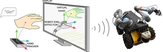
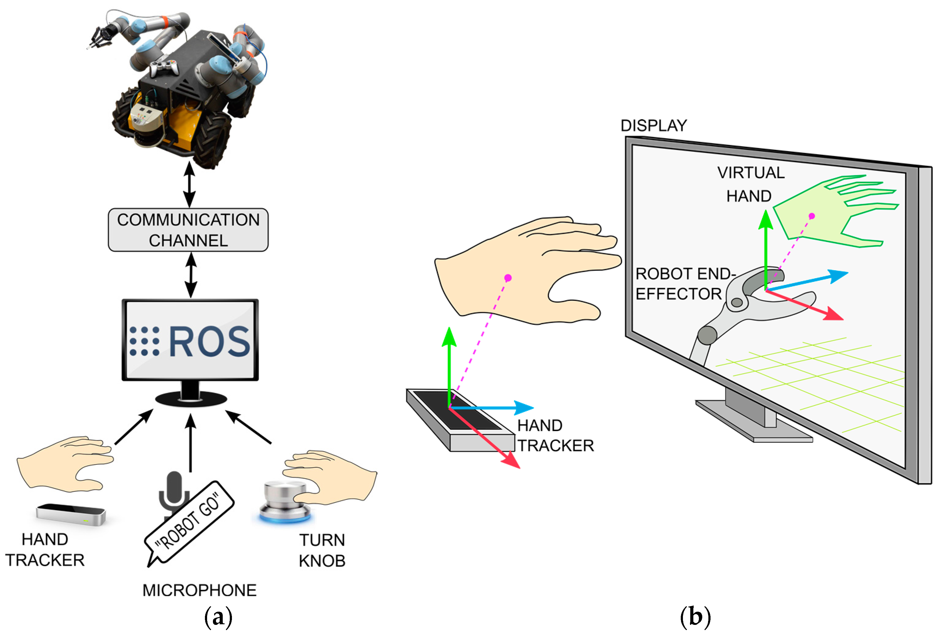
The command interface (Figure 2a) utilizes gestural and vocal input devices, which allow concurrent task execution and monitoring. The GUI design utilizes the key findings of [14]: the only source of visual feedback is a single window, where graphical content is fused into a Mixed-Reality (MR) scene (Figure 2b and Figure 3). The MR scene combines the model-based representation of the robot’s current state with remote sensor data and operator input, creating a virtual representation of robot’s surroundings augmented with VFs. The tracked hand (Figure 2b and Figure 3) is interpreted as a virtual pointer for commanding the pose of interest (mobile base, left manipulator, right manipulator, etc.). A rotational knob maps operator input to the task’s scale. Thus, a comfortable 15 cm hand-waving gesture scales to any commanded move such as traversing a lab (>10 m), an EEF gross motion (≈10 cm), or fine adjustments to a tool’s location (<1 mm). The user does not need to be quantitatively aware of the actual scale any more than a photographer using a camera’s zoom lens needs to know the magnification value. It has been established that scaling helps reduce the operator burden when executing high-precision (<1 mm) tasks [37].
The left hand of the operator hovers above the hand pose tracker while the right hand adjusts scaling via the turn knob. The operator’s point-of-view (POV) of the MR scene is updated to predefined perspectives based on the control mode and view constraints (as described in Section 3.1.3), which further reduces the operator’s cognitive load required to construct a mental model of the remote robot and its workspace [38]. The system allows the operator to manually select any perspectives.
Hardware agnosticism is partially ensured by using the Robot Operating System (ROS) [39]. In ROS, subprograms (nodes) communicate asynchronously via a publisher-subscriber structure using standard TCP/IP protocols. Each node can be independently executed or stopped. Thus, nodes responsible for control, image processing, motion planning, etc. can be distributed to satisfy computational or other restrictions. For example, it is practical to handle planning and execution tasks on the robot’s onboard computer in low-bandwidth scenarios to avoid delay during autonomous task execution. Or if the robot has limited computational power, it may be preferable to perform intensive computations remotely and transmit easy-to-process waypoints at a rate commensurate with the available bandwidth.
TeMoto has been successfully tested on the robot platforms shown in Figure 1. For hand tracking we use a Leap Motion Controller (LMC) [40], a depth sensing camera, which—in our set-up—is embedded in the computer’s keyboard. LMC provides low-latency tracking and does not require markers attached to the operator’s hands. LMC is able to track all the joints of a hand, from which TeMoto utilizes the palm’s position and orientation to create a simplified virtual representation of the arm. A Griffin PowerMate infinite turn knob allows the operator to change the scaling factor intuitively (i.e., logarithmically).
3.1. Software Architecture
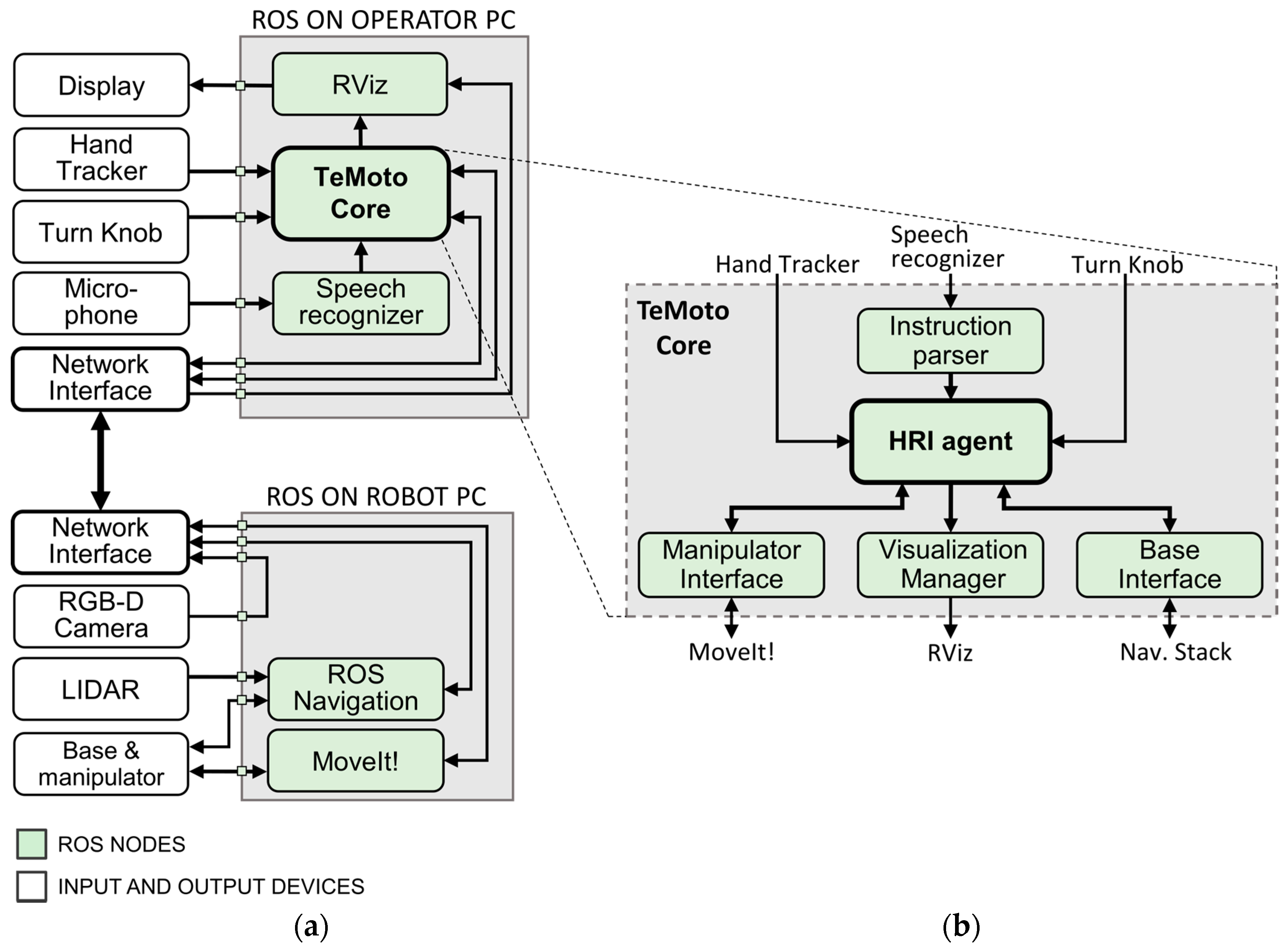
TeMoto’s architecture is shown in Figure 4. Note the architecture is depicted as structurally distributed between two computers but the ROS nodes (green) can be instantiated on any number of computers.
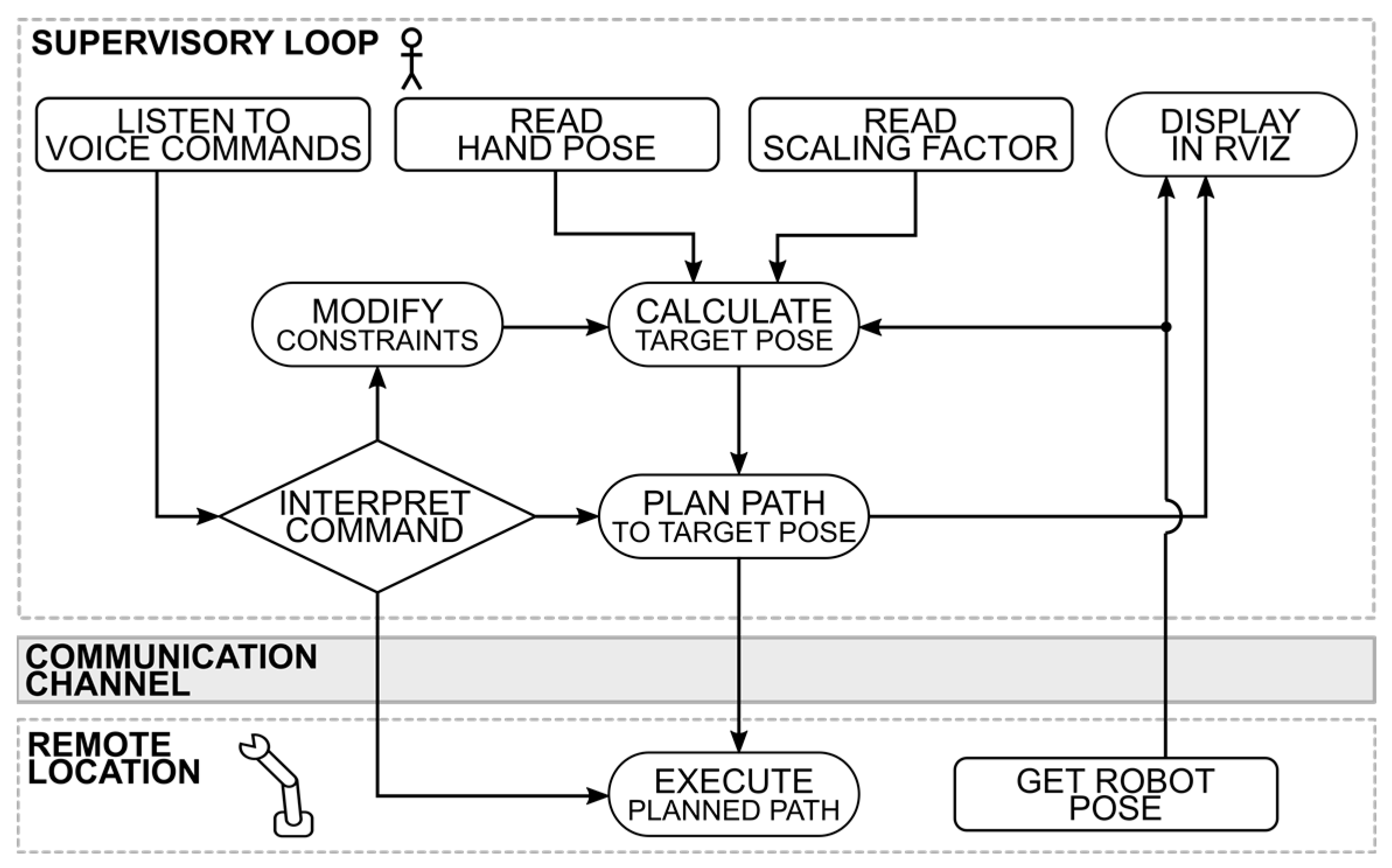
When possible, TeMoto leverages ROS packages to minimize the redevelopment of existing capabilities. MoveIt! [41] (which internally utilizes RViz [39] and the Open Motion Planning Library (OMPL) [42]) provides the robot’s kinematics, motion planning and 3D visualization. ROS Navigation [43] generates collision-free paths for the mobile base. Voice commands are converted to text using a speech recognition package Pocketsphinx [44]. The TeMoto Core contains 5 developed modules, implemented as ROS nodes. Instruction parser acts as a filter that detects valid voice commands. Manipulator Interface and Base Interface provide means for manipulation and mobile navigation respectively. The Human-Robot Interface (HRI) agent directs teleoperation system based on operator input and feedback data. It is also responsible for keeping track of the system’s overall status. The HRI agent is structured as a supervisory controller (Figure 5), which continuously monitors command inputs (hand pose, scaling factor and voice commands). Visualization Manager processes all operator graphical guidance and constraint related data for visualizing in RViz. The hand pose, robot pose and surrounding environment are visually combined after adjusting for current scale.
Voice commands allow the operator to
- plan and/or execute a path,
- manage (change) the point of view on the MR scene, and
- switch control modes (manipulation, navigation).
Functionally, TeMoto’s Visualization Manager interprets HRI agent’s state and generates intuitive visual feedback that helps the operator to comprehend any applied motional constraints (via voice commands). Additionally, it adjusts operator’s perspective in the MR scene based on the state of the HRI agent. Using RViz simplifies integration and visualization for different data structures to a single MR scene as it includes plug-ins for visualizing and manipulating common data structures (e.g., point clouds, meshes, maps, trajectories, coordinate frames, etc.).
To complete the architecture’s structure, several analytical and technical contributions were necessary, which are explained in the following sections. They include:
- Model-based robot representation—Central to TeMoto is putting the robot “at hand.” The robot’s model must provide accurate representation of its system parameters, configuration and environment when depicted from any perspective the operator selects.
- Mobile manipulation planning—MoveIt! provides collision-free motion-planning for manipulators and ROS Navigation for autonomous ground movement but there is no documented method for integrating these capabilities.
- Automated selection of user perspectives—To reduce the operator’s cognitive load and errors due to the lack of SA, the system must automatically adjust the operator’s POV of the MR scene for the selected motion type.
- Visual cuing and active constraints—Visual cues as well as the representation of active constraints via VFs in the MR scene are necessary to align user intention with the robot’s behavior.
- Sensor fusion—Environmental, robot and visual cue data come from multiple non-deterministic sources and must be effectively managed and presented to the user.
- Verbal interactive capabilities—The voice interface must also be intuitive, which requires careful compromise between flexibility (so operators do not have to memorize very specific language) and unambiguity (so the command’s meaning is clear and specific). The operator also requires audio feedback.
Each of these is discussed in more detail below.
3.1.1. Model-Based Robot Representation
The operator must be aware the robot’s configuration states and its surroundings. Thus, every aspect of the MR scene centers on the model-based representation whose joint states continuously match the real robot. The kinematical, geometrical and visual properties of the robot are described using Unified Robot Description Format (URDF) [39] that defines all relations and constraints between its links as well as provides other visual components (2D map, RGB-D camera data, etc.) a frame of reference. Figure 6 depicts a model-based representation for an industrial manipulator and how the LMC coordinate frame (Figure 6a) is linked to its EEF while maintaining human centric control approach (Figure 6a,b).
3.1.2. Mobile Manipulation Planning
Path-planning with the ROS Navigation libraries do not consider the dynamic reach of the manipulator and MoveIt! does not include the mobile base’s Degrees-of-Freedom (DoF). This creates additional burden on the operator who currently segregates mobility and manipulation motion commands. Thus, we developed a Mobile Manipulation (MM) planning algorithm (MM planner) which virtually expands the manipulator’s kinematic description to include the mobile base. A similar approach was recently described in [45] where a system automatically switched between manipulation and navigation subsystems depending on the distance between current and target EEF location. The system determined velocity commands but did not provide a trajectory planning framework. The approach below combines existing navigation and EEF manipulation software tools which then provide a complete trajectory planning solution including path planning and collision avoidance.
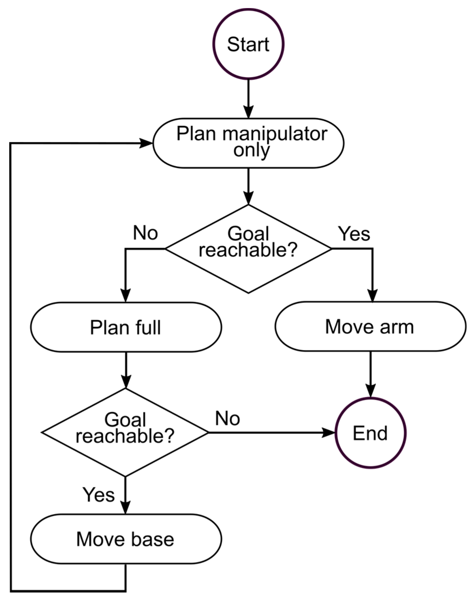
Figure 7 illustrates the integrated MM planner. Upon receiving a EEF target pose, a plan is generated considering only the manipulator (Figure 8a). If the target pose is reachable then the plan is executed. If the target is not reachable, then a new plan is generated using the manipulator’s Extended Kinematic Description (EKD) (Figure 8b). If a successful collision-free plan is found, the end location and rotation of the mobile base are extracted and automatically passed to the navigation planner. Once the mobile platform has reached the target, the process is repeated until the target EEF pose is attained. The algorithm ensures that the EEF reaches the target pose given a single operator command and recovers from positional uncertainty (e.g., dynamic obstacles) between the intended and achieved poses for the mobile base.
To formulate the EKD, the coordinate transformation of an arbitrary geometrical object r from EEF coordinate frame () to world coordinate frame is described as
where:
- and are the poses of object in the world and EEF coordinate frame;
- is the mobile base coordinate frame;
- , , are manipulator joints, i.e., transforms from 0th to nth joint, ending with the EEF joint;
- is a coordinate frame of the EEF.
The Equation (1) describes the manipulator’s serial kinematic chain. The joint states are represented by (Equation (2)). Figure 8b depicts the joint representations with additional virtual joints , and that describe the mobile base’s DoF. and constrain the base to the xy-plane and allows the base to rotate around z-axis. The kinematic chain can now be described by Equation (3) with the extended state vector (Equation (4)).
MoveIt! first solves the problem using the EKD. If a solution is found, the necessary values , and are then sent to ROS Navigation which ensures the base safely arrives at its location prior to finishing the move using MoveIt!
3.1.3. Automated User Perspectives
To reduce cognitive load due to robot misalignment with operator perspective, the HRI agent (Figure 5) automatically adjusts the operator’s point-of-view on the MR scene based on the control mode or instructions (verbal or gestural) from the operator. For example, navigation is best managed when the operator has a top-down view (Figure 9). Perspectives are predefined for control modes and workspace constraints. Figure 6 depicts the natural and inverted perspectives for guiding the EEF. For both perspectives, the LMC frame remains stationary with respect to the operator. In natural perspective (Figure 6b) the operator’s right, forward and up (given in LMC frame as in Figure 6a) are interpreted as the right, forward and up of the robot end-effector, respectively. In the inverted control perspective (Figure 6c), the robot is rotated 180° around y-axis of the LMC frame, i.e., around the up vector of the operator’s hand.
3.1.4. Visual Cues
With the model robot integrated with sensor data, TeMoto provides a variety of visual cues for perceiving depth, motion constraints, visualizing planned paths and indicating distance between the virtual hand and EEF. For example, the HRI agent allows the operator to select/combine four visual cue modalities for representing motion constraints:
Each constraint is visualized as a virtual fixture informing the operator of the constraint. By default, when no constraints are applied, a rectangular parallelepiped is rendered together with a red arrow and a translucent 3D bounding box for depth perception (Figure 10a). The red parallelepiped serves as a virtual marker representing hand pose (the parallelepiped is aligned with the centroid of operator’s palm) while the arrow depicts in-scale displacement between the EEF and gesturally designated pose. When the orientation is maintained (Figure 10b), the red parallelepiped is not rendered into the MR scene. When movements are constrained to 2D space, the virtual markers are represented in yellow (Figure 10c,d). A distance numerical marker, indicating the distance between the center points of the EEF and virtual hand, is often added to MR scene to provide a scale feedback. Furthermore, trajectories can be temporally visualized prior to execution in the MR scene.
3.1.5. Sensor Fusion
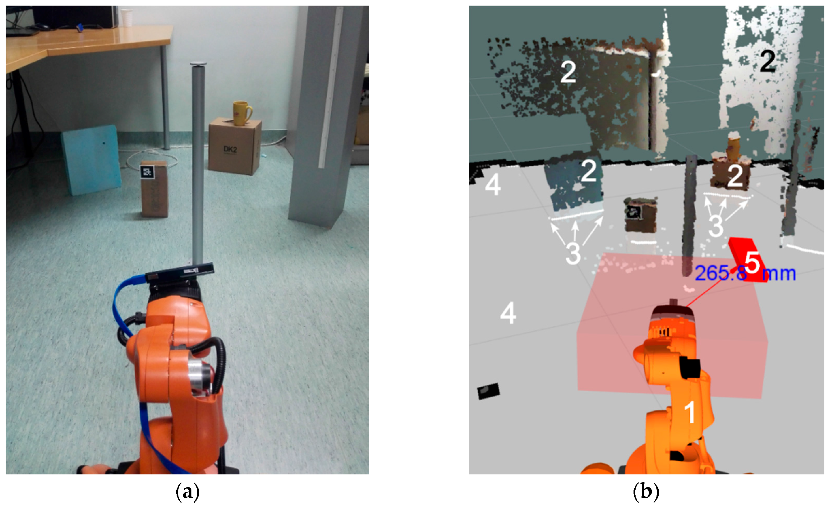
From the perspective of safe and reliable task execution, it is critical that the operator is fully aware of the state of the robot in its environment. Also, the data necessary for the operator to make this determination must be suitably presented. Many telerobotic systems suffer due to overly complex operator interfaces. For this effort, we distinguish between the complexity of the interface (to be avoided) and the complexity of the task/environment (to be shared). Tracking sensor data from multiple sources (e.g., displays) dramatically increases the operator’s cognitive load and chances for error. A number of studies emphasize the importance of choosing what and how to represent data from multiple sensors [14,25,26]. The MR scene combines data from a variety of sources providing the user a clean and intuitive visual interface while maintaining high situational awareness. Figure 11 compares the operator’s perspective over MR scene (Figure 11b) and a photo of the actual environment with the robot platform (Figure 11a). The sensor-fused mixed-reality workspace (Figure 11b) visualizes different types of data, including:
- robot joint state representation as a 3D model,
- point cloud stream from a RGB-D camera,
- point cloud stream from a 2D LIDAR,
- 2D map of the environment, and
- virtual representation of the operator’s hand with relevant visual cues.
The 2D map and the robot’s location on it is acquired using a Simultaneous Localization and Mapping (SLAM) package GMapping [46] that utilizes 2D LIDAR and odometry data. Point clouds originating from LIDAR and RGB-D camera are inserted into the MR scene by defining a coordinate transformation between the respective device and a designated attachment location. Thus, transformations between the 2D map and both point clouds are known and overlaid in a single MR scene with the visual cues and robot model. The MR scene is viewable either from any 2D perspective rendered on a monitor or virtual reality headset.
3.1.6. Verbal Interaction
Verbal interaction allows the operator to focus on the visual feedback, rather than manipulating a controller mapped to the robot’s task space. The structure of a verbal instruction follows the command language approach. Each instruction is predefined and paired with a callback procedure triggered when a matching word sequence is detected. The instruction set is greater than the number of callback procedures to provide flexibility without creating command ambiguity. For example, both “robot, please move” and “robot, please execute” map to a procedure where the system executes a motion task. Figure 12 gives an overview of the verbal interaction cycle. The speech recognition module converts audio commands to text. The text stream is sent to the instruction parser to identify known word sequences. Valid instructions are sent to the HRI agent triggering a callback procedure. Finally, audio feedback is synthesized using sound-play package [47] to communicate task status to the user.
Commands are designed to minimize misinterpretation for critical actions. Verbal instructions that only influence the virtual workspace can be one word (“navigation” or “manipulation” to switch control modes), whereas triggering movement requires uttering a phrase with three distinct words (e.g., “robot please execute”). Table 1 shows 3 of the 22 currently defined verbal instructions, demonstrating the differences between the verbal instructions for critical and non-critical actions.
4. Implementation and Demonstration
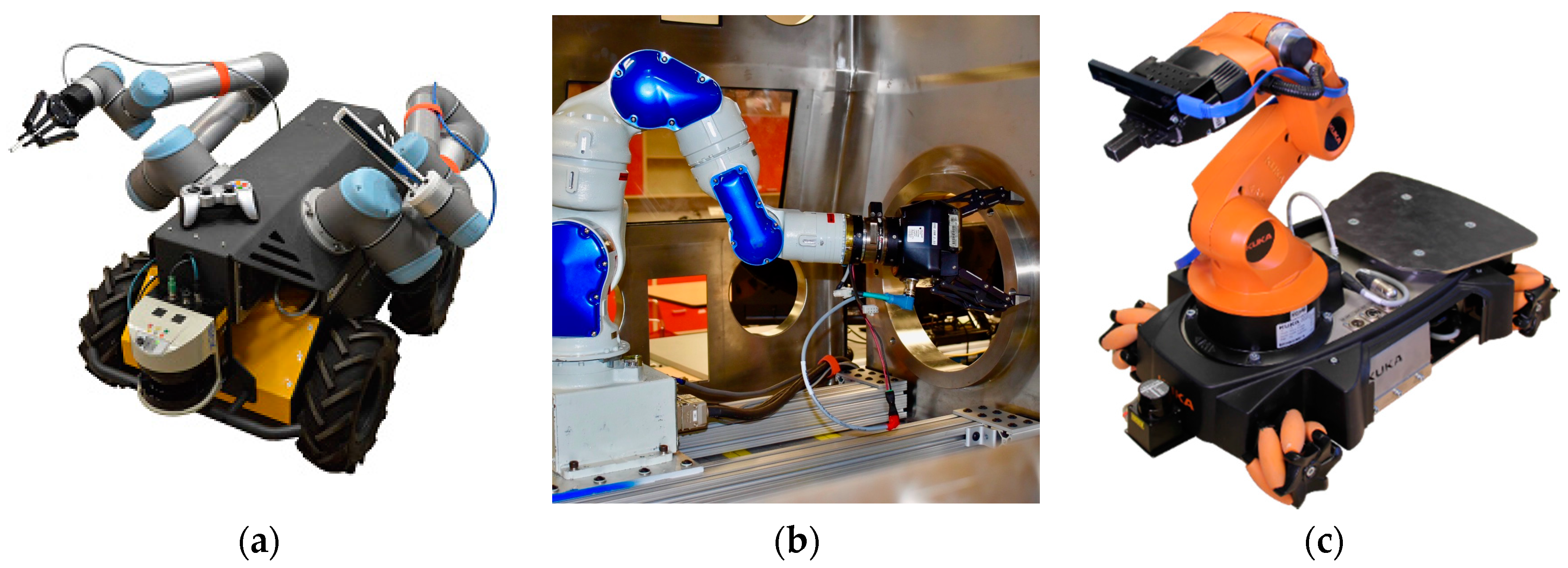
TeMoto was utilized and evaluated on three functionally different robotic systems (Figure 1).
- Yaskawa SIA10 and SIA5D 7 DoF industrial manipulators used separately to validate usability for high-precision tasks (e.g., threading a needle).
- VaultBot is a dual-arm mobile manipulator with a Clearpath Husky mobile base and two 6 DoF UR5 manipulators used for inspection tasks. Both large-scale navigation and small-scale manipulation were achieved.
- Omnidirectional KUKA youBot is a mobile 5 DoF manipulator for achieving MM planning for the robot end-effector, i.e., combined collision-free trajectory planning for the mobile base and serial manipulator.
By demonstrating TeMoto on multiple hardware configurations completing a variety of tasks, it was possible to fully evaluate all aspects of TeMoto. Furthermore, it was necessary to evaluate TeMoto using techniques that easily scale from evaluation methods common in the literature and often limited to a single hardware system completed a small (often just one) set of tasks. Thus, unique tasks were conducted with each setup to demonstrate all developed functional capabilities as well as hardware agnosticism. All three systems have publicly available ROS hardware interface packages. All three platforms utilized ROS Indigo and Ubuntu 14.04 LTS. The remainder of this section outlines the tasks completed by each of the three platforms.
4.1. Yaskawa SIA5D—High Precision Stationary Industrial Manipulator
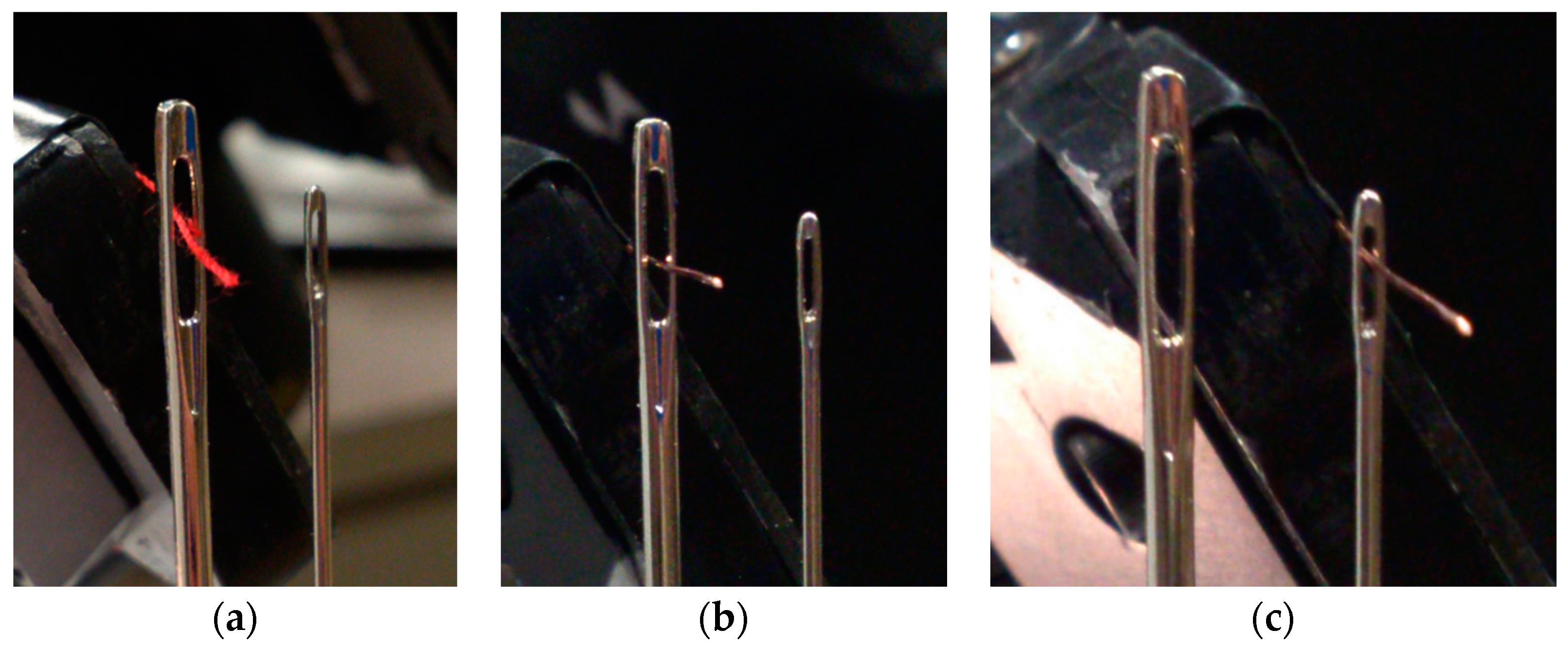
When completing tasks inside a glovebox, operators have a limited view, reduced dexterity and ergonomic challenges. Responding to accidents in such spaces is difficult or impossible. The completed demonstration (needle threading) also illustrates the advantages of scaling the operator’s gestures to a sub-millimeter task commands [37] which are impossible to complete via manually through gloveports. Thread was attached to the robot’s EEF while the needle was kept upright and stationary. Copper wire and sewing thread were used to thread needles with eye widths in the range from 1 mm to 0.5 mm. Figure 13 shows the needles and threads after a successful task using the hands-free user interface, verifying the feasibility for high-precision tasks.
With approval from the Institutional Review Board of the University of Texas at Austin, a comparative study was completed with 12 engineering students, who were asked to use two teleoperation controllers to complete the thread-a-needle task using:
- the proposed gesture—and speech-based teleoperation system, TeMoto, and
- a more conventional drag-and-drop interaction using a computer mouse to manipulate so-called interactive markers [48] in RViz.
Subjects had 5 min to familiarize themselves with both interfaces. After the “training” period, they threaded a needle using both methods in a randomized order, 3 attempts per each method. Task completion times and number of move commands were recorded and results showed a slight decrease in average task completion times with the gesture/speech interface, taking 94 s (σ = 61 s) with the mouse-based interface and 86 s (σ = 42 s) with TeMoto [37]. The results imply that without prior experience, humans are as fluent with gestural control as with the deeply-rooted mouse-based interface for this particular task and in this particular environment.
4.2. VaultBot—Mobile Manipulation by Switching between Navigation and Manipulation Control
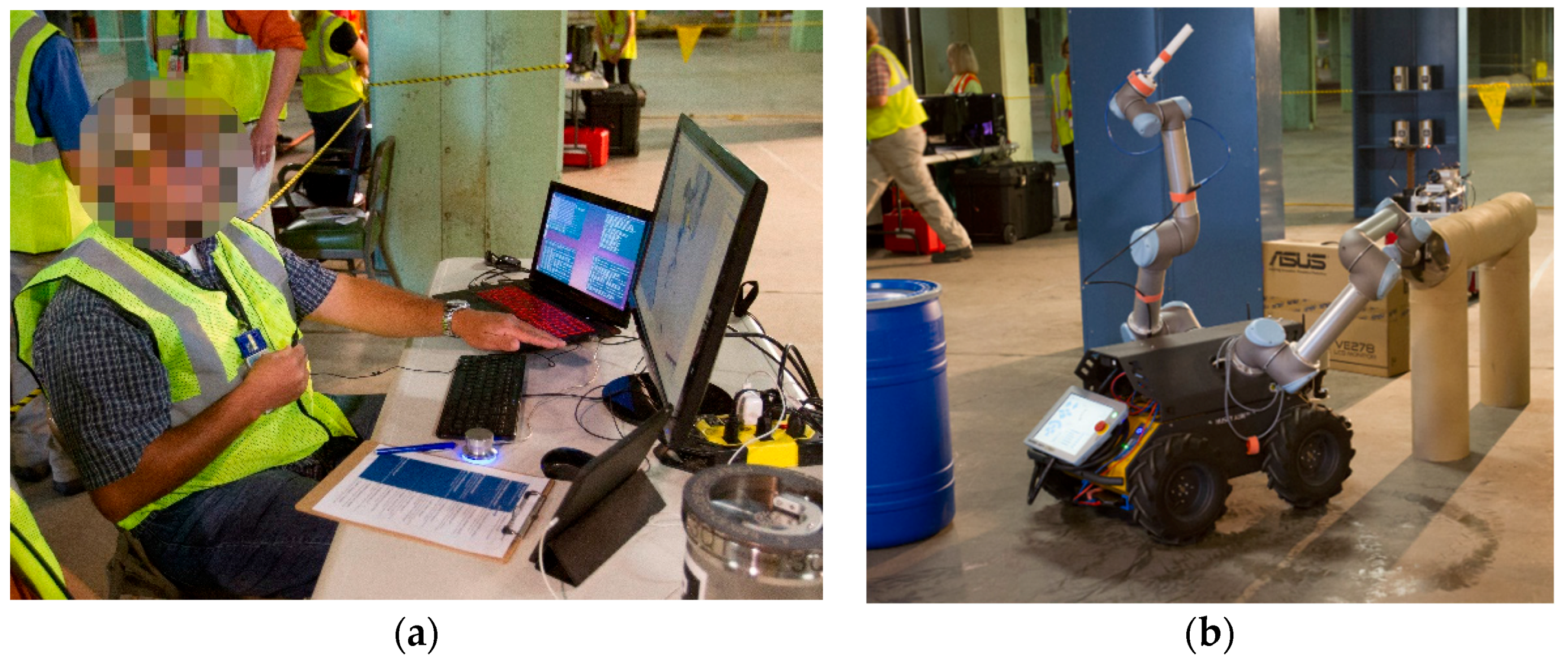
Motivated by applications in large, hazardous environments (nuclear decommissioning, offshore drilling, etc.), a mobile dual-arm manipulator platform was controlled using TeMoto to navigate a cluttered environment to inspect ducts and pipes. VaultBot (Figure 1a and Figure 14b) is a skid-steer Clearpath Husky base with two UR5 manipulators. One supports a RealSense R200 RGB-D camera while the other has a Robotiq two-finger gripper and a GoPro camera. A SICK LMS511 2D LIDAR, UM6 IMU, wireless router and on-board laptop are included. Further details about VaultBot can be found in [49].
TeMoto with VaultBot was put into real-life test at the U.S. Department of Energy’s (DOE’s) Gaseous Diffusion Plant in Portsmouth, OH. The goal was to use on-site workers with no prior robotic experience as operators to remotely complete Decommissioning and Decontamination (D&D) tasks [51]. More specifically, their objective was to read a sign placed ~300 mm inside a pipe opening. The operator first moved the system across the room (~7 m), then moved the gripper holding the GoPro camera inside the pipe to read the sign. The GoPro camera stream was sent to a separate screen independent of the TeMoto interface. The operator had no line of sight with the task space. The operator completed the task after 45 min of training. All the capabilities mentioned above were present during this demonstration except the MM planning and motion capability. From the DOE report on the effort: “The operator used gesture control to plan a path that the robot then followed to an area of interest. The robot moved autonomously, including utilization of obstacle avoidance. […] The hardware and software worked flawlessly. Open libraries using ROS is well done and better than most universities” [51]. While this demonstration generated positive as well as useful feedback for TeMoto, it also demonstrated the difficulties associated with developing larger studies in these environments given the security requirements, limits on the number of eligible technicians, overall cost, variety of tasks to consider and logistics for completing such tests in DOE government facilities. This in turn, motivates the need for more general evaluation techniques.
4.3. YouBot—Mobile Manipulation with Full Configuration Motion Planning for Navigation and Manipulation
TeMoto was tested on KUKA youBot Figure 1c, which has an omnidirectional base, 5 DoF manipulator, Hokuyo URG-04LX-UG01 2D LIDAR and on-board computer. This effort included the EKD capabilities for MM planning eliminating the need to switch between navigation and manipulation control modes, i.e., segregated planning. Note that the EKD addresses the spatial deficiencies of the 5 DoF manipulator since the base’s additional 3 DoF are automatically included when executing any commanded move. The advantages of MM planner can be evaluated by comparing the minimum number of operator instructions required to complete a manipulation task.
Consider an inspection task where the target pose is outside the EEF’s current workspace. Table 2 summarizes the operator instructions for completing the task in segregated and MM planning mode. Without the EKD, navigation control mode must be used at least once—yielding 2 instructions for switching control mode and 1 for repositioning the base. The EEF target pose requires one additional command, for a total of 4 commands assuming no operator error. With EKD, the target pose can be achieved with a single instruction with no chance for human error. This also halves the number of voice commands necessary for the operator to learn, further reducing training time and the potential for ambiguity.
The above demonstrations validate the capabilities and wide range of applications where TeMoto would be useful. But they also illustrate key challenges for making such assertions generally. User studies can focus too narrowly on specific tasks or environments. Studies may not be possible in certain cases. Also, regular upgrades in the software’s capabilities (which are common in large, open source, collaborative efforts), quickly render user studies as dated. Thus, the following section summarizes the existing and proposed methods to scale evaluation techniques and to address these issues.
5. System Performance Evaluation
Prior to use in the field, any proposed human-machine interface must be evaluated after all major components are developed and fully integrated. User interface effectiveness can be evaluated from three perspectives: (1) task completion (success rates), (2) task completion efficiency (number of steps, duration, etc.), (3) command latency or delay and (4) reduction in operator burden by reducing cognitive load, training time, etc.
We note that latency is a non-issue given TeMoto relies on discrete (semi-autonomous) commands and not direct tele-operation. Also, the time delay between giving a command and the robot executing the command was not significant in any our tests. Though, delays can vary wildly in a general task space (i.e., long delays for the Mars Rover, no delay for a tethered proximal system, etc.) but our solution should minimize the impact of such delays given its ability to complete discrete commands in the presence of dynamic obstacles.
Performance evaluations can be analytical—which has the advantages of task/environment independence—or empirically completed through user studies. Data collected from user studies can be both quantitative and qualitative. The following section reviews efforts to evaluate TeMoto both analytically and empirically, with the purpose of gaining insight into its effectiveness for completing general tasks across a range of environments. The results are summarized below.
5.1. Task Completion Rates
In separate study, completion and performance metrics were collected for needle threading (i.e., high-precision) tasks [37]. The users quickly adapted to the gesture-based input and used it as efficiently as a mouse-based input. Similar results were obtained by [22] where they demonstrated that touch-free hand tracking interfaces have faster learning rates than touch-based interfaces. Task completion was further validated for mobile manipulation during DOE’s Portsmouth demonstrations. A worker with no prior robotic experience (and 45 min of training) successfully completed a pipe inspection task using hand tracking input and verbal instructions. The youBot consistently completed the commanded task of moving its EEF to a location outside of its initial reachable space but the primary focus of these efforts was to address completion efficiency while reducing the operator’s burden. Thus, the results are discussed in sections below.
5.2. Task Completion Efficiency
Two metrics to evaluation completion efficiency are completion time and number of steps. Lab studies documented in [37] show a reduction in task completion time for threading a needle (average reduced from 94 s to 86 s) compared to EEF control using an interactive marker (n = 36). The maximum completion time was more dramatically reduced from 300 s to 200 s.
The issue with empirical time completion studies is that they are task specific and difficult to generalize. To address this issue, let’s consider the number of operator instructions as an efficiency metric. The number of instructions necessary to complete EEF relocation were shown in Table 2, which exemplifies the increased task efficiency possible when commands are performed at a higher LOA (MM planning). This analysis can be generalized and include the potential for user and planner error. Equations (5) and (6) estimate the number of instructions required to finish tasks with n EEF relocations (steps) to a position initially unreachable without moving the base. Let fp represent the number of planner failures (i.e., how many times the operator had to re-specify a goal due to the planner failures) and fr represent the number of reachability failures during the navigation process of segregated planning (i.e., how many times the operator navigated to a location where the EEF still could not reach the goal.)
where:
- —number of operator instructions in segregated planning mode,
- —number of operator instructions in MM planning mode,
- —relation between and , which estimates the efficiency of MM planning over segregated planning,
- —number of EEF relocations to initially unreachable positions,
- —number of reachability failures,
- —number of planner failures.
The efficiency criteria quantifies the relative efficiency, i.e., how many times is MM planning more efficient than segregated planning in terms of number of given voice instructions. By introducing the terms ( and ) that represent the potential failures during the execution, quantifies the benefits of the increased autonomy. Table 3 contains an illustrative set of the calculated values of with respect to different values of failure rates, given as the percentage of steps n. For example, if the task can be ideally completed with minimal amount of 10 steps and the failure rate is 50%, the total number of retries is and thus the overall step count is 15. If the failure rate is >100% then this implies that the number of retries is greater than the minimal number of required steps.
Given that the operator does not fully comprehend the kinematic dexterity of the manipulator, it is plausible that the operator might encounter a significant amount of reachability failures with segregated planning. Hence the results (Table 3) of this theoretical assessment indicate that operator will benefit from MM planning as the cognitive load and execution time is reduced. This assessment considered only the voice instructions needed for completing the task. The operator may have to switch between different perspectives during navigation, which further increases the command count per single task execution cycle. While this analysis is applied to determine the increased efficiency by using MM planning, TeMoto’s interface enables this type of analysis for any added autonomous feature since its input commands are discrete (i.e., a gesture or utterance) and not continuous (i.e., moving/holding the joystick to the left, right, etc.). Thus, this approach provides important insight into the maximum potential benefit for a given user interface.
5.3. Reducing the Operator’s Cognitive Load
It is tempting to assert there is a cognitive load reduction when command count is reduced but this conclusion is incorrect. In chess, executing moves is simple compared to the necessary prior thought. Executing a single joint motion is simple compared to the cognitive burden of determining its impact on the EEF and designated task. TeMoto utilizes a single interface and a human’s natural abilities to filter graphical data. To accommodate high-precision task execution, virtual fixtures imposed motion constraints when necessary to reduce the operator’s burden. The operator’s point-of-view of the task was adjustable when needed to give the operator a better understanding of the task space. Coordinate transforms from the operator frame to task space are handled automatically which further reduces cognitive load. In contrast to current systems, the operator is no longer responsible for internally mapping the task space to EEF space to joint space to input device space to a hand motion. In TeMoto, the operator gives commands directly into the task space with a hand motion or voice command. Cognitive burden in this category is fully minimized by reducing the number of context switches to zero. In summary, TeMoto reduced or removed the following operator cognitive tasks.
- Path planning and collision detection.
- Collecting data from multiple sources (just one screen)
- Mentally mapping from the task frame to the input frame
- Context switching between the task space, robot space and user interface device.
- Completing tasks with inputs outside of an operator’s comfortable ergonomic range.
6. Conclusions
The paper presents TeMoto: a hardware agnostic, highly intuitive supervisory teleoperation system for operating manipulators and mobile platforms. A combination of gestural control via scalable hand tracking and speech input are used to command remote systems. ROS was leveraged whenever possible and allow TeMoto developers to focus on the user experience and not back-end robot software development. The results show that untrained operators can quickly understand and use TeMoto as well as the well-established mouse input, even to run systems too complex to be efficiently operated with only a mouse input. To reach this conclusion, TeMoto was evaluated using established, task-specific metrics (task completion time, number of steps, user studies) as well as task-independent metrics quantifying efficiency and operator context switching.
Despite their availability, gesture-based input devices are not common and the technology has yet to reach its full potential. One could argue that as the technology for gesture detection and hand tracking evolves, the intuitiveness of the proposed teleoperation system is likely to increase. The integration of this device with a natural language input further increased the usability of the system and reduced command ambiguity. As an analogy, consider how much more effective one is at giving instructions to another individual when the instructor can both speak and use gestures.
In the future specific objects of interest can be highlighted in the MR scene when detected by the computer vision algorithms. In this way, an operator’s attention can be brought to objects that would otherwise have been disregarded. Adopting VR headset to look upon the MR scene can improve the way operator perceives the robot and task space (increases SA) whereas the IMU within the headset allows more intuitive access to different point-of-views on the task at hand. Furthermore, by adding context-based virtual fixtures, the system can be used to visualize other sensor data (thermal, radiation, etc.) without the need to create another interface screen and adding to the operator’s cognitive burden. Another ongoing effort is collaborating with researchers who study user interface design and then apply identified principles on this topic to further improve TeMoto.
Acknowledgments
This work was in part supported by Los Alamos National Laboratory. R.V. and K.K. acknowledge the support from Estonian Centre of Excellence in IT (EXCITE) funded by the European Regional Development Fund and the grant MOBTP7 by Mobilitas Pluss, receiving funding from the European Regional Development Fund. K.K. would also like to thank the Research Scholar Program of the Baltic-American Freedom Foundation.
Author Contributions
K.K. and M.P. conceived and designed the proposed system and experiments; K.K. and R.V. implemented the system and performed the experiments; R.V. wrote the paper with strong input from M.P. and K.K.
Conflicts of Interest
The authors declare no conflict of interest.
References
- De Gregory, J.; Lujan, R.; Haley, D.; Hamel, W. Robotics and intelligent machines: A DOE critical technology roadmap. In Proceedings of the 2001 Waste Management Symposium, Tucson, AZ, USA, 1 March 2001; pp. 1–13. [Google Scholar]
- Rimando, R. EM Science of Safety (SoS): Robotics Technology Thrust. DOE National Cleanup Workshop: Alexandria, VA, USA, 15 September 2016. Available online: https://energy.gov/sites/prod/files/2016/09/f33/DOE%20NCW%20-%20160915%20FINAL%20REV01.pdf (accessed on 22 October 2017).
- Nagatani, K.; Kiribayashi, S.; Okada, Y.; Otake, K.; Yoshida, K.; Tadokoro, S.; Nishimura, T.; Yoshida, T.; Koyanagi, E.; Fukushima, M.; et al. Emergency response to the nuclear accident at the Fukushima Daiichi Nuclear Power Plants using mobile rescue robots. J. Field Robot. 2013, 30, 44–63. [Google Scholar] [CrossRef]
- Asada, H. The Current Status and Future Strategic Plan of Decommissioning of Fukushima Daiichi Nuclear Power Stations Using Remote-Controlled Robot Technology. In Proceedings of the IROS Open Forum on the Future of Robotics and Automation in Nuclear Facilities & Environments, Vancouver, CA, USA, 26 September 2017. [Google Scholar]
- Leshin, L.A.; Mahaffy, P.R.; Webster, C.R.; Cabane, M.; Coll, P.; Conrad, P.G.; Archer, P.D.; Atreya, S.K.; Brunner, A.E.; Buch, A.; et al. Volatile, Isotope and Organic Analysis of Martian Fines with the Mars Curiosity Rover. Science 2013, 341, 1238937. [Google Scholar] [CrossRef] [PubMed]
- Fong, T.; Zumbado, J.R.; Currie, N.; Mishkin, A.; Akin, D.L. Space Telerobotics: Unique Challenges to Human-Robot Collaboration in Space. Rev. Hum. Factors Ergon. 2013, 9, 6–56. [Google Scholar] [CrossRef]
- Palep, J.H. Robotic assisted minimally invasive surgery. J. Minimal Access Surg. 2009, 5, 1–7. [Google Scholar] [CrossRef] [PubMed]
- Vandegrift, G.F.; Conner, C.; Hofman, G.L.; Leonard, R.A.; Mutalib, A.; Sedlet, J.; Walker, D.E.; Wiencek, T.C.; Snelgrove, J.L. Modification of Targets and Processes for Conversion of 99Mo Production from High- to Low-Enriched Uranium. Ind. Eng. Chem. Res. 2000, 39, 3140–3145. [Google Scholar] [CrossRef]
- Parasuraman, R.; Sheridan, T.B.; Wickens, C.D. A model for types and levels of human interaction with automation. IEEE Trans. Syst. Man Cybern. Part Syst. Hum. 2000, 30, 286–297. [Google Scholar] [CrossRef]
- Bruemmer, D.J.; Few, D.A.; Boring, R.L.; Marble, J.L.; Walton, M.C.; Nielsen, C.W. Shared Understanding for Collaborative Control. IEEE Trans. Syst. Man Cybern. Part Syst. Hum. 2005, 35, 494–504. [Google Scholar] [CrossRef]
- Brabec, C.; Schroeder, K.; Williams, J.; O’Neil, B.; Pryor, M. Reducing the operator’s burden during teleoperation involving contact tasks. In Proceedings of the 2011 ANS International Topical Meeting on Robotics and Remote Systems, Knoxville, TN, USA, 7–10 August 2011; pp. 202–212. [Google Scholar]
- Sheridan, T.B. Space Teleoperation through Time Delay: Review and Prognosis. IEEE Trans. Robot. Autom. 1993, 9, 592–606. [Google Scholar] [CrossRef]
- Thompson, J.; Pryor, M. Spatial interface for user-centric robotic teleoperation and demonstration on a high precision task. In Proceedings of the Workshop on Tele-operation at the IEEE Conference on Intelligent Robots and Systems, Chicago, IL, USA, 14 September 2014. [Google Scholar]
- Yanco, H.A.; Norton, A.; Ober, W.; Shane, D.; Skinner, A.; Vice, J. Analysis of human-robot interaction at the DARPA robotics challenge trials. J. Field Robot. 2015, 32, 420–444. [Google Scholar] [CrossRef]
- Murphy, R.R.; Schreckenghost, D. Survey of metrics for human-robot interaction. In Proceedings of the ACM/IEEE International Conference on Human-Robot Interaction, Tokyo, Japan, 3–6 March 2013; pp. 197–198. [Google Scholar] [CrossRef]
- Murphy, R. Disaster Robotics; Intelligent robotics and autonomous agents; The MIT Press: Cambridge, MA, USA, 2014; ISBN 978-0-262-02735-9. [Google Scholar]
- Zue, V. Eighty challenges facing speech input/output technologies. Proc. Sound Sense 2004, B179–B195. [Google Scholar]
- Devine, S.; Rafferty, K.; Ferguson, S. Real time robotic arm control using hand gestures with multiple end effectors. In Proceedings of the 2016 UKACC 11th International Conference on Control (CONTROL), Belfast, UK, 31 August–2 September 2016; p. 5. [Google Scholar] [CrossRef]
- Du, G.; Zhang, P.; Mai, J.; Li, Z. Markerless Kinect-based hand tracking for robot teleoperation. Int. J. Adv. Robot. Syst. 2012, 9. [Google Scholar] [CrossRef]
- Chen, S.; Ma, H. Hand Gesture Based Robot Control System Using Leap Motion. Int. Conf. Intell. Robot. Appl. 2015, 581–591. [Google Scholar] [CrossRef]
- Sarkar, A.; Patel, K.A.; Ram, R.K.G.; Capoor, G.K. Gesture control of drone using a motion controller. In Proceedings of the 2016 International Conference on Industrial Informatics and Computer Systems, CIICS 2016, Sharjah, United Arab Emirates, 13–15 March 2016. [Google Scholar] [CrossRef]
- Zhou, T.; Cabrera, M.E.; Low, T.; Sundaram, C.; Wachs, J. A Comparative Study for Telerobotic Surgery Using Free Hand Gestures. J. Hum. Robot Interact. 2016, 5, 1–28. [Google Scholar] [CrossRef]
- Chen, J.Y.C.; Haas, E.C.; Barnes, M.J. Human performance issues and user interface design for teleoperated robots. IEEE Trans. Syst. Man Cybern. Part C Appl. Rev. 2007, 37, 1231–1245. [Google Scholar] [CrossRef]
- Draper, M.; Calhoun, G.; Ruff, H.; Williamson, D.; Barry, T. Manual versus speech input for unmanned aerial vehicle control station operations. In Proceedings of the Human Factors and Ergonomics Society 47th Annual Meeting, Denver, CO, USA, 13–17 October 2003; SAGE Publications: Los Angeles, CA, USA, 2003; Volume 47, pp. 109–113. [Google Scholar] [CrossRef]
- Ferre, M.; Aracil, R.; Sánchez-Uran, M.A. Stereoscopic human interfaces. IEEE Robot. Autom. Mag. 2008, 15, 50–57. [Google Scholar] [CrossRef] [Green Version]
- Suwazono, T.; Nakamura, N.; Yamashita, A. Development of the remote-controlled platform truck for handling heavy object and the remote control human interface for the disaster response. Adv. Robot. 2015, 29, 165–169. [Google Scholar] [CrossRef]
- Kaber, D.B.; Endsley, M.R. The effects of level of automation and adaptive automation on human performance, situation awareness and workload in a dynamic control task. Theor. Issues Ergon. Sci. 2004, 5, 113–153. [Google Scholar] [CrossRef]
- Muszynski, S.; Stuckler, J.; Behnke, S. Adjustable autonomy for mobile teleoperation of personal service robots. In Proceedings of the IEEE International Workshop on Robot and Human Interactive Communication, Paris, France, 9–13 September 2012; pp. 933–940. [Google Scholar] [CrossRef]
- Jipp, M. Levels of automation: Effects of individual differences on wheelchair control performance and user acceptance. Theor. Issues Ergon. Sci. 2014, 5, 479–504. [Google Scholar] [CrossRef]
- Rosenberg, L.B. Virtual fixtures: Perceptual tools for telerobotic manipulation. In Virtual Reality Annual International Symposium; IEEE: Piscataway Township, NJ, USA, 1993; pp. 76–82. [Google Scholar] [CrossRef]
- Abbott, J.; Marayong, P.; Okamura, A. Haptic virtual fixtures for robot-assisted manipulation. Robot. Res. 2007, 49–64. [Google Scholar] [CrossRef]
- Park, Y.S.; Zhao, X.; Korthals, S. Simulation of Augmented Telerobotic Operation. In Proceedings of the 2014 International Symposium on Optomechatronic Technologies (ISOT), Seattle, WA, USA, 5–7 November 2014; pp. 242–246. [Google Scholar] [CrossRef]
- DeJong, B.P.; Faulring, E.L.; Colgate, J.E.; Peshkin, M.A.; Kang, H.; Park, Y.S.; Ewing, T.F. Lessons Learned From a Novel Teleoperation Testbed. Ind. Robot Int. J. 2006. [Google Scholar] [CrossRef]
- Castillo-Cruces, R.A.; Wahrburg, J. Virtual fixtures with autonomous error compensation for human-robot cooperative tasks. Robotica 2010, 28, 267–277. [Google Scholar] [CrossRef]
- Rydén, F.; Chizeck, H.J.; Kosari, S.N.; King, H.; Hannaford, B. Using kinect and a haptic interface for implementation of real-time virtual fixtures. In Proceedings of the 2nd Workshop on RGB-D: Advanced Reasoning with Depth Cameras (in Conjunction with RSS 2011), Berkeley, CA, USA, 12 July 2014; RSS: Los Angeles, CA, USA, 2011. [Google Scholar]
- Kosari, S.N.; Rydén, F.; Lendvay, T.S.; Hannaford, B.; Chizeck, H.J. Forbidden region virtual fixtures from streaming point clouds. Adv. Robot. 2014, 28, 1507–1518. [Google Scholar] [CrossRef]
- Kruusamäe, K.; Pryor, M. High-precision telerobot with human-centered variable perspective and scalable gestural interface. In Proceedings of the 2016 9th International Conference on Human System Interactions, Portsmouth, UK, 6–8 July 2016; pp. 190–196. [Google Scholar] [CrossRef]
- Labonte, D.; Boissy, P.; Michaud, F. Comparative analysis of 3-D robot teleoperation interfaces with novice users. IEEE Trans. Syst. Man Cybern. Part B Cybern. 2010, 40, 1331–1342. [Google Scholar] [CrossRef] [PubMed]
- Smart, W.; Quigley, M.; Gerky, B. Programming Robots with ROS; O’Reily Media: Sebastopol, CA, USA, 2015; ISBN 978-1-4493-2389-9. [Google Scholar]
- Weichert, F.; Bachmann, D.; Rudak, B.; Fisseler, D. Analysis of the accuracy and robustness of the leap motion controller. Sensors 2013, 13, 6380–6393. [Google Scholar] [CrossRef] [PubMed]
- Chitta, S.; Sucan, I.; Cousins, S. MoveIt! IEEE Robot. Autom. Mag. 2012, 19, 18–19. [Google Scholar] [CrossRef]
- Sucan, I.A.; Moll, M.; Kavraki, L.E. The Open Motion Planning Library. IEEE Robot. Autom. Mag. 2012, 19, 72–82. [Google Scholar] [CrossRef]
- Guimarães, R.L.; de Oliveira, A.S.; Fabro, J.A.; Becker, T.; Brenner, V.A. ROS Navigation: Concepts and Tutorial. In Robot Operating System (ROS); Studies in Computational Intelligence; Springer: Cham, Switzerland, 2016; pp. 121–160. ISBN 978-3-319-26052-5. [Google Scholar]
- Huggins-Daines, D.; Kumar, M.; Chan, A.; Black, A.W.; Ravishankar, M.; Rudnicky, A.I. Pocketsphinx: A Free, Real-Time Continuous Speech Recognition System for Hand-Held Devices. In Proceedings of the 2006 IEEE International Conference on Acoustics Speed and Signal Processing Proceedings, Toulouse, France, 14–19 May 2006; Volume 1, pp. I-185–I-188. [Google Scholar] [CrossRef]
- Wrock, M.R.; Nokleby, S.B. An automatic switching approach to teleoperation of mobile-manipulator systems using virtual fixtures. Robotica 2017, 35, 1773–1792. [Google Scholar] [CrossRef]
- Grisetti, G.; Stachniss, C.; Burgard, W. Improved techniques for grid mapping with rao-blackwellized particle filters. IEEE Trans. Robot. 2007, 23, 34–46. [Google Scholar] [CrossRef]
- Sound_Play—ROS Wiki. Available online: http://wiki.ros.org/sound_play (accessed on 6 January 2018).
- Gossow, D.; Leeper, A.; Hershberger, D.; Ciocarlie, M. Interactive Markers: 3-D User Interfaces for ROS Applications [ROS Topics]. IEEE Robot. Autom. Mag. 2011, 18, 14–15. [Google Scholar] [CrossRef]
- Sharp, A.; Kruusamäe, K.; Ebersole, B.; Pryor, M. Semiautonomous dual-arm mobile manipulator system with intuitive supervisory user interfaces. In Proceedings of the 2017 IEEE Workshop on Advanced Robotics and its Social Impacts (ARSO), Austin, TX, USA, 8–10 March 2017; pp. 1–6. [Google Scholar] [CrossRef]
- Pryor, M. Operator evaluation of a mobile robotic systems for inventory, inspection and contamination survey tasks in D&D environments. In Proceedings of the Waste Management Symposia, Phoenix, AZ, USA, 5 March 2017. [Google Scholar]
- United States Department of Energy. Portsmouth Robotic Demo Final Report; United States Department of Energy: Portsmouth, OH, USA, 2017.
Figure 1.
Robot hardware systems used to evaluate the developed TeMoto interface: (a) UT Austin’s dual-arm mobile manipulator, (b) UT Austin’s 7 DoF Yaskawa SIA5 and (c) Univ. of Tartu’s KUKA 5 DoF youBot.
Figure 1.
Robot hardware systems used to evaluate the developed TeMoto interface: (a) UT Austin’s dual-arm mobile manipulator, (b) UT Austin’s 7 DoF Yaskawa SIA5 and (c) Univ. of Tartu’s KUKA 5 DoF youBot.

Figure 2.
(a) Conceptual design of the teleoperation system; (b) Visualization of the tracked hand.

Figure 3.
TeMoto hardware set-up. The red marker in (a) represents the operator’s hand mapped to mobile system’s task space. Views from behind and in front of the robot are shown in (b,c), respectively. The (c) also includes visual cues representing motion constraints in translucent yellow area.
Figure 3.
TeMoto hardware set-up. The red marker in (a) represents the operator’s hand mapped to mobile system’s task space. Views from behind and in front of the robot are shown in (b,c), respectively. The (c) also includes visual cues representing motion constraints in translucent yellow area.
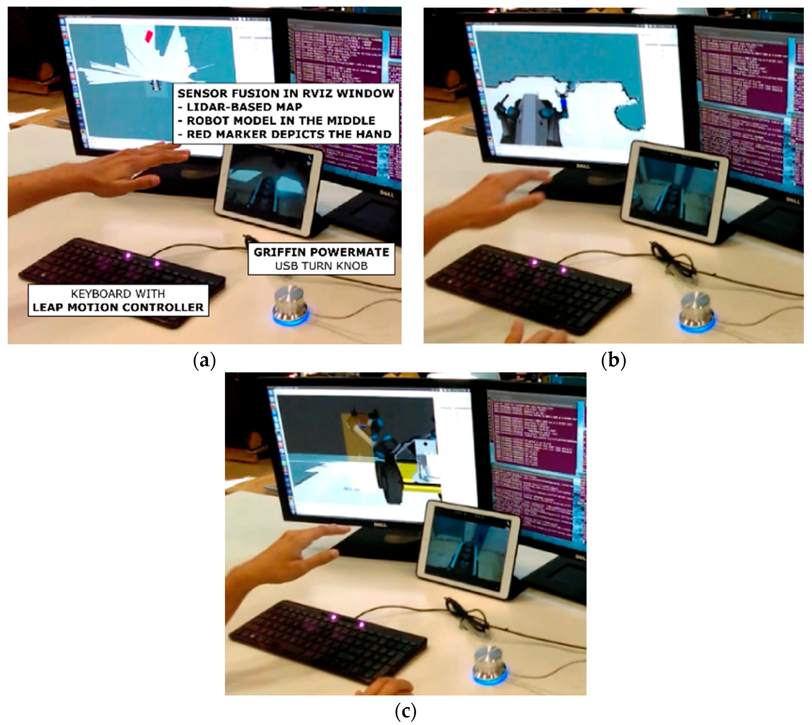
Figure 4.
(a) TeMoto Software architecture and (b) internal structure of its core constituting of 5 modules.
Figure 4.
(a) TeMoto Software architecture and (b) internal structure of its core constituting of 5 modules.

Figure 5.
Command flow of the HRI agent.

Figure 6.
(a) Operator’s perception and the coordinate system for LMC. Two control perspectives for the robot end-effector: (b) natural and (c) inverted.
Figure 6.
(a) Operator’s perception and the coordinate system for LMC. Two control perspectives for the robot end-effector: (b) natural and (c) inverted.
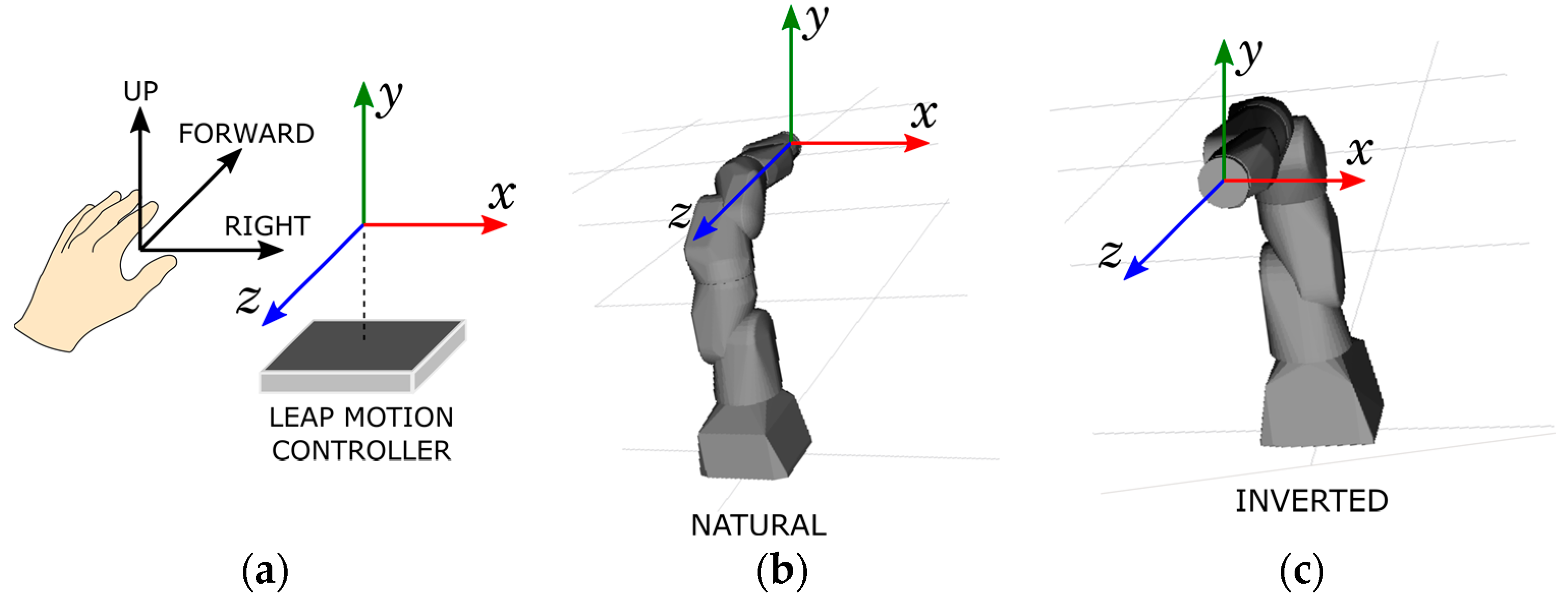
Figure 7.
Working principle of the integrated MM planner.

Figure 8.
(a) Regular robot joint configuration; (b) Extended Kinematic Description.
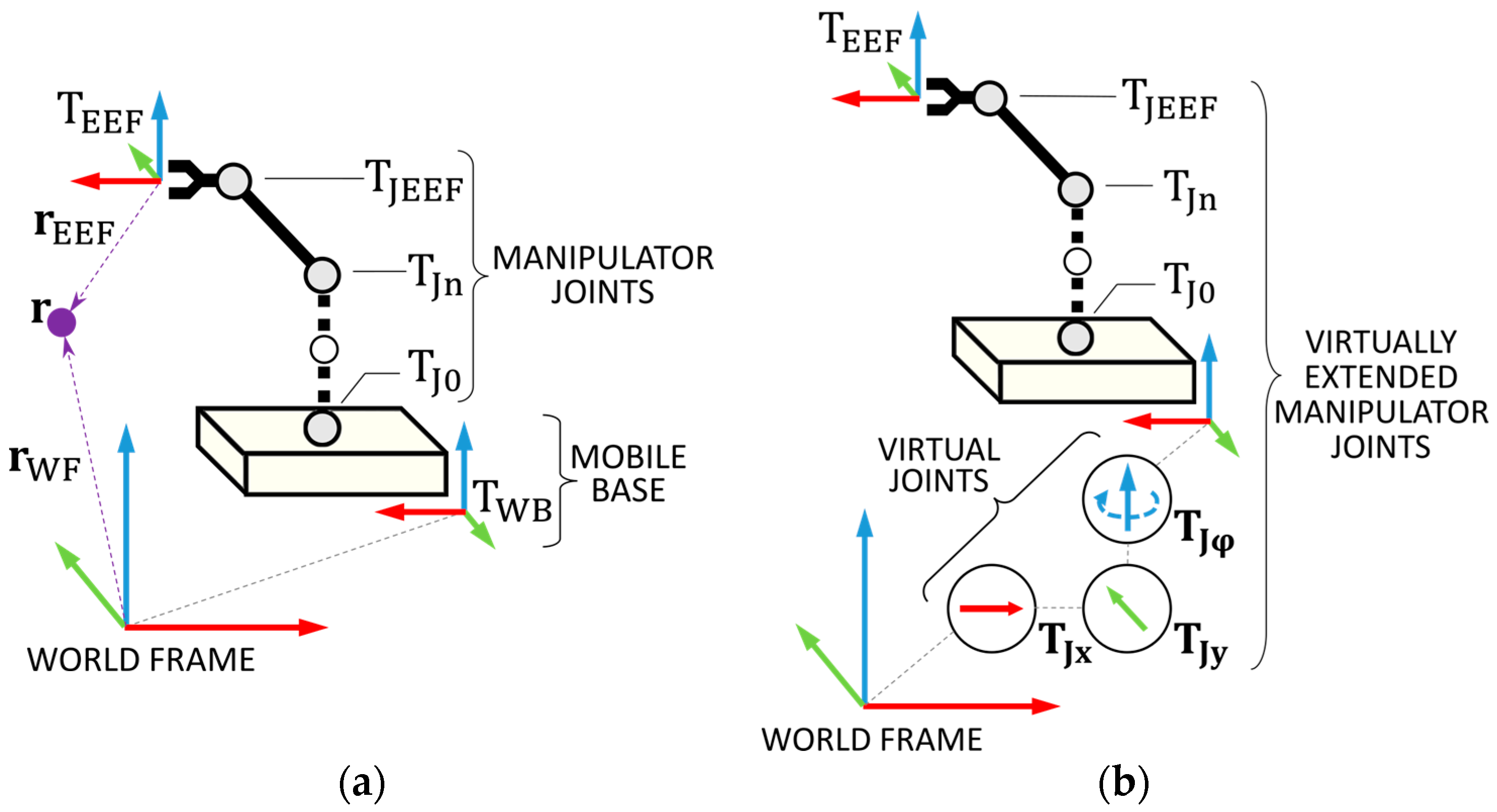
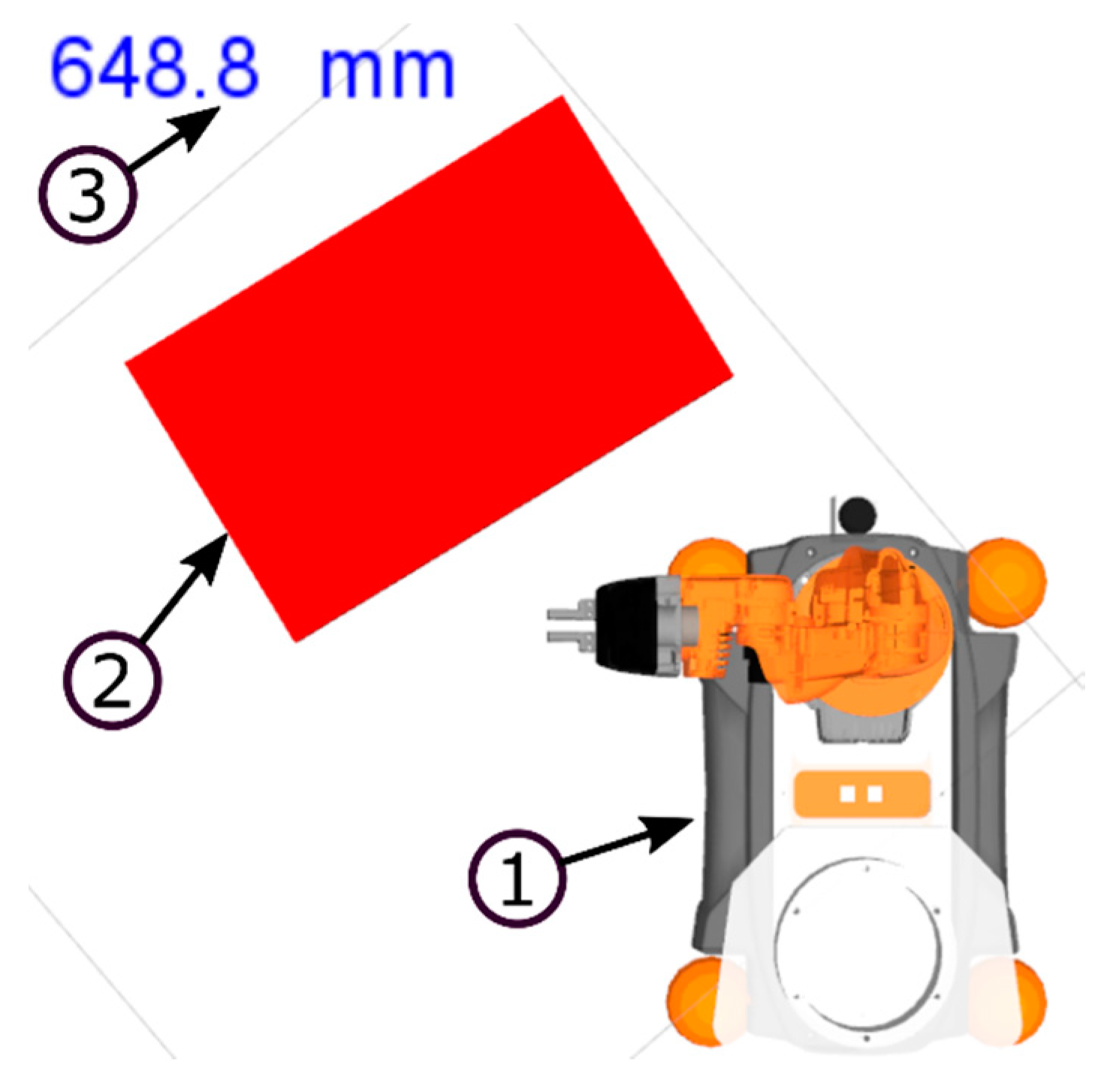
Figure 9.
Top-down view on the MR scene for navigating the robot with following visual elements: ① 3D model of robot; ② The gesture guided red marker with a dynamically updated ③ distance indicator.
Figure 9.
Top-down view on the MR scene for navigating the robot with following visual elements: ① 3D model of robot; ② The gesture guided red marker with a dynamically updated ③ distance indicator.

Figure 10.
Example of different constraints on the youBot in natural (a), (b) and inverted (c), (d) control perspectives. (a) No constraints; (b) Orientation maintained; (c) Constrained to a direction; (d) Constrained to a plane.
Figure 10.
Example of different constraints on the youBot in natural (a), (b) and inverted (c), (d) control perspectives. (a) No constraints; (b) Orientation maintained; (c) Constrained to a direction; (d) Constrained to a plane.
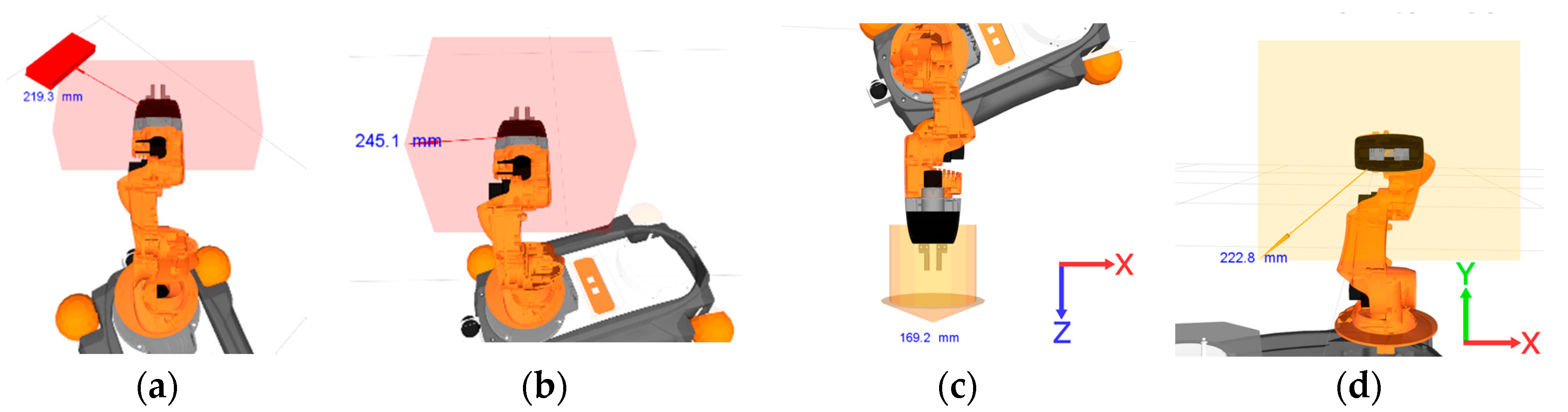
Figure 11.
(a) Image of a test environment where the robot operates in. (b) Resulting sensor fusion with (1) robot’s 3D model using joint data, (2) point-cloud stream from RGB-D camera, (3) point cloud stream from 2D LIDAR, (4) 2D environment map, (5) gestural hand location with scale and constrained motion visual cues.

Figure 12.
Verbal interaction cycle.
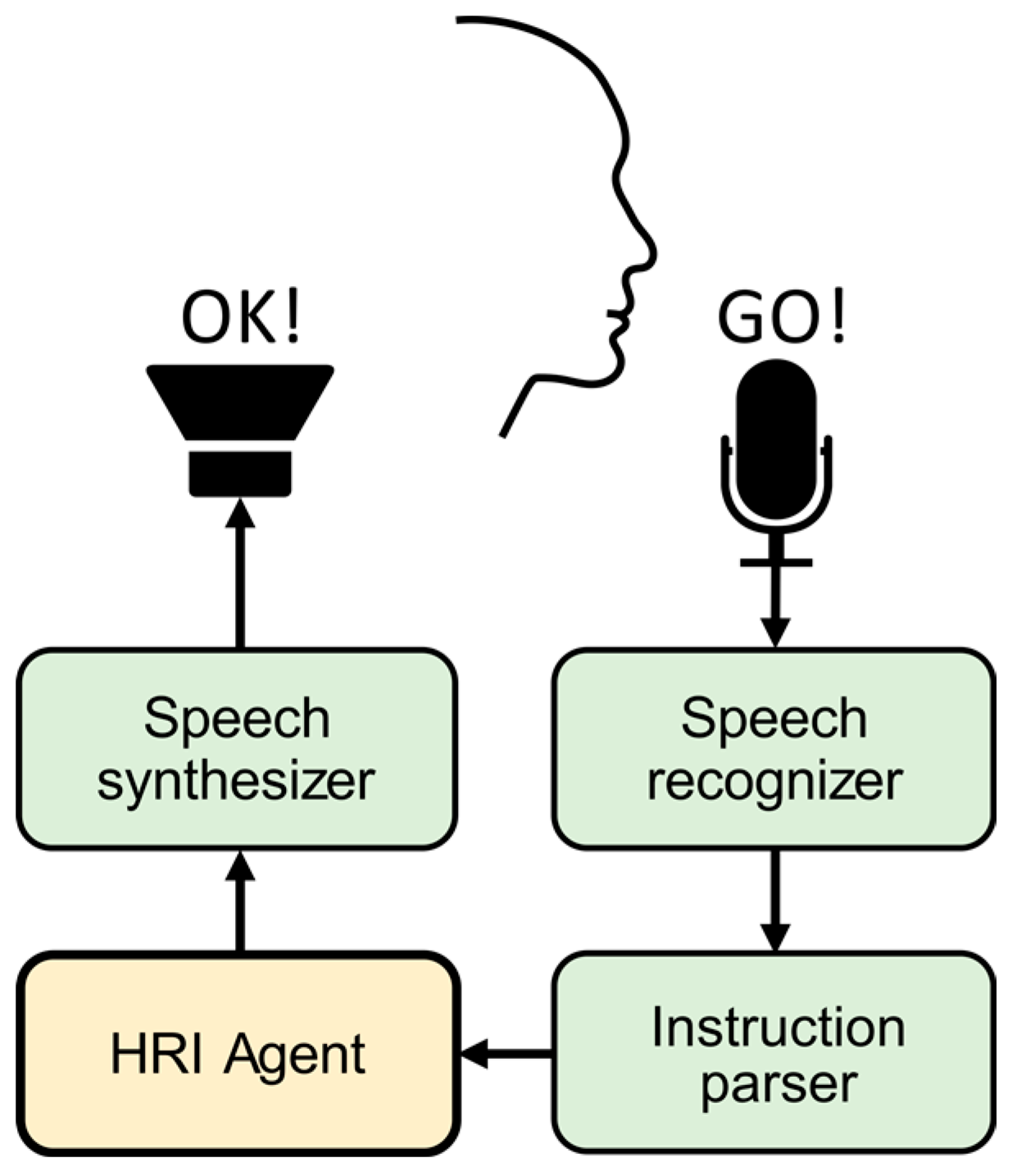
Figure 13.
Camera view of the large needle (eye width of 1 mm) threaded by (a) the red sewing thread and (b) the copper wire and small needle (eye width of 0.5 mm) threaded by (c) the copper wire.
Figure 13.
Camera view of the large needle (eye width of 1 mm) threaded by (a) the red sewing thread and (b) the copper wire and small needle (eye width of 0.5 mm) threaded by (c) the copper wire.

Figure 14.
(a) US steel worker using TeMoto for (b) inspecting a duct at DOE’s Gaseous Diffusion Plant in Portsmouth, OH (Note the operator is also wearing a headset microphone, blurred in photo) [50].
Figure 14.
(a) US steel worker using TeMoto for (b) inspecting a duct at DOE’s Gaseous Diffusion Plant in Portsmouth, OH (Note the operator is also wearing a headset microphone, blurred in photo) [50].

Table 1.
Partial list of predefined verbal instructions and their criticality.
| Command | Criticality | Function |
|---|---|---|
| “navigation” | not critical | Switches the system to navigation mode |
| “limit directions” | not critical | Constrains the virtual hand to a xy-plane (Figure 10d) |
| “robot please execute” | critical | Executes a previously planned trajectory |
Table 2.
A minimum number of commands required in the case of segregated and MM planning for obtaining a new EEF pose that is initially out of reach.
Table 2.
A minimum number of commands required in the case of segregated and MM planning for obtaining a new EEF pose that is initially out of reach.
| Segregated Planning | MM Planning | |
|---|---|---|
| Control mode switching | 2 | 0 |
| Navigation instructions | 1 | 0 |
| Manipulation instructions | 1 | 1 |
| Instructions in total | 4 | 1 |
Table 3.
Calculated values of efficiency with respect to different values of failure rates.
| (% of n) | (% of n) | |
|---|---|---|
| 0% | 0% | 4 |
| 50% | 50% | 4.3 |
| 100% | 100% | 4.5 |
| 50% | 0% | 3 |
| 100% | 0% | 2.5 |
| 0% | ||
| 0% | 50% | 6 |
| 0% | 100% | 8 |
| 0% |
© 2018 by the authors. Licensee MDPI, Basel, Switzerland. This article is an open access article distributed under the terms and conditions of the Creative Commons Attribution (CC BY) license (http://creativecommons.org/licenses/by/4.0/).
Share and Cite
MDPI and ACS Style
Valner, R.; Kruusamäe, K.; Pryor, M. TeMoto: Intuitive Multi-Range Telerobotic System with Natural Gestural and Verbal Instruction Interface. Robotics 2018, 7, 9. https://doi.org/10.3390/robotics7010009
AMA Style
Valner R, Kruusamäe K, Pryor M. TeMoto: Intuitive Multi-Range Telerobotic System with Natural Gestural and Verbal Instruction Interface. Robotics. 2018; 7(1):9. https://doi.org/10.3390/robotics7010009
Chicago/Turabian StyleValner, Robert, Karl Kruusamäe, and Mitch Pryor. 2018. "TeMoto: Intuitive Multi-Range Telerobotic System with Natural Gestural and Verbal Instruction Interface" Robotics 7, no. 1: 9. https://doi.org/10.3390/robotics7010009
Note that from the first issue of 2016, this journal uses article numbers instead of page numbers. See further details here.