External Control of Dissipative Coupling in a Heterogeneously Integrated Photonic Crystal—SOI Waveguide Optomechanical System

 , and
, and 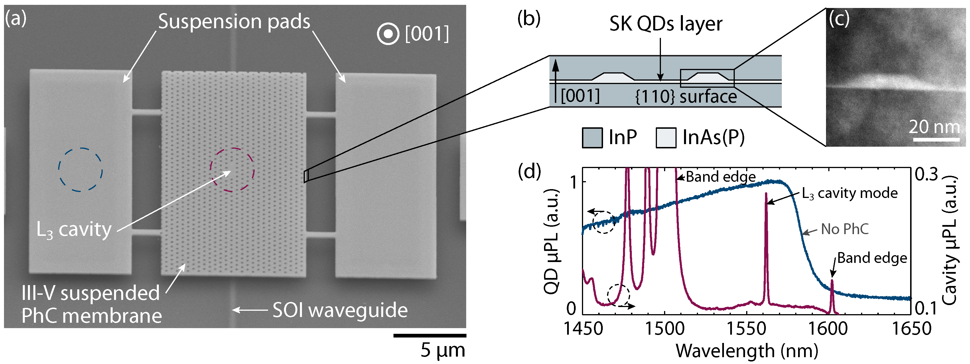
Abstract
:1. Introduction
2. Materials and Methods
2.1. Device Fabrication
2.2. Photonic Crystal Design
3. Results
3.1. System Description
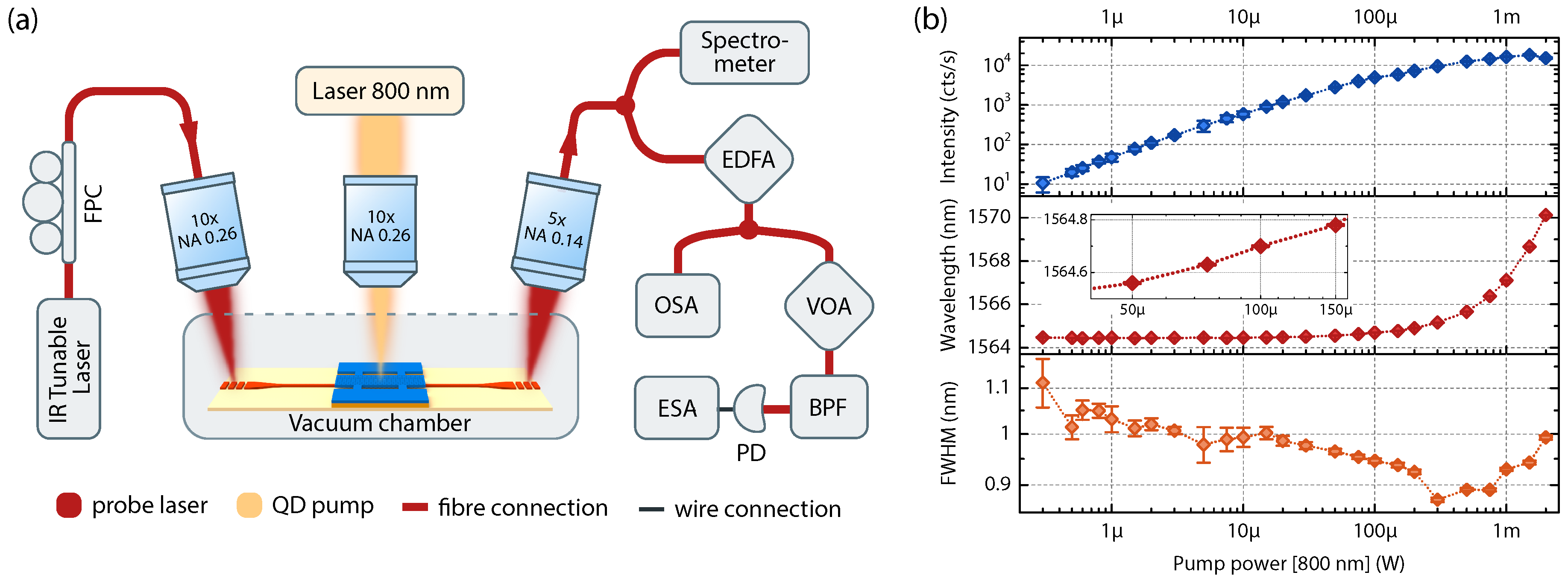
3.2. QDs Response to a Non-Resonant Optical Pump
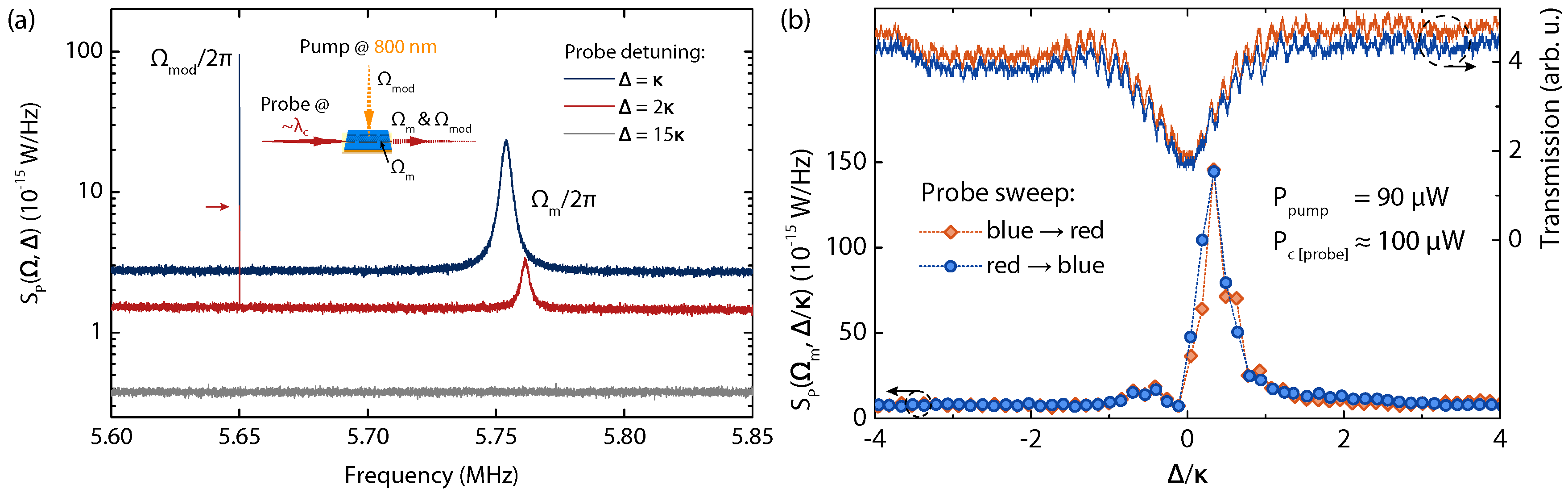
3.3. Optomechanical Transduction of Non-Resonant Pump
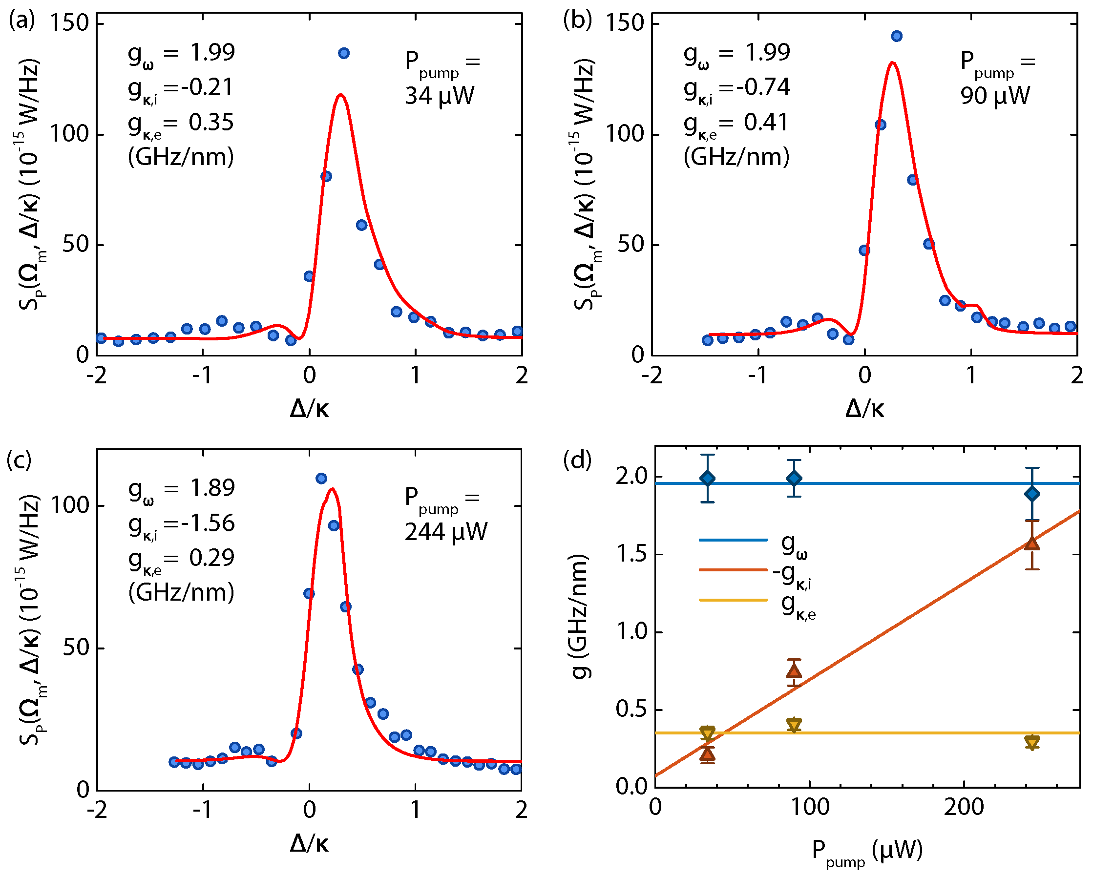
3.4. Tailored Optomechanical Couplings
4. Discussion and Conclusions
Acknowledgments
Author Contributions
Conflicts of Interest
Abbreviations
| CW | continuous wave |
| EBL | electron beam lithography |
| FDTD | finite difference in time domain |
| FWHM | full width at half maximum |
| InAs(P) | indium arsenide phosphide |
| InGaAs | indium gallium arsenide |
| InP | indium phosphide |
| PhC | photonic crystal |
| PL | micro-photoluminescence |
| Si | silicon |
| silicon dioxide | |
| QD | quantum dot |
| SOI | silicon-on-insulator |
References
- Aspelmeyer, M.; Kippenberg, T.J. Cavity Optomechanics; Springer: Berlin/Heidelberg, Germany, 2014. [Google Scholar]
- Li, M.; Pernice, W.H.P.; Tang, H.X. Reactive cavity optical force on microdisk-coupled nanomechanical beam waveguides. Phys. Rev. Lett. 2009, 103, 223901. [Google Scholar] [CrossRef] [PubMed]
- Wu, M.; Hryciw, A.C.; Healey, C.; Lake, D.P.; Jayakumar, H.; Freeman, M.R.; Davis, J.P.; Barclay, P.E. Dissipative and dispersive optomechanics in a nanocavity torque sensor. Phys. Rev. X 2014, 4, 021052. [Google Scholar] [CrossRef]
- Sawadsky, A.; Kaufer, H.; Nia, R.M.; Tarabrin, S.P.; Khalili, F.Y.; Hammerer, K.; Schnabel, R. Observation of generalized optomechanical coupling and cooling on cavity resonance. Phys. Rev. Lett. 2015, 114, 043601. [Google Scholar] [CrossRef] [PubMed]
- Hryciw, A.C.; Wu, M.; Khanaliloo, B.; Barclay, P.E. Tuning of nanocavity optomechanical coupling using a near-field fiber probe. Optica 2015, 2, 491–496. [Google Scholar] [CrossRef]
- Tsvirkun, V.; Surrente, A.; Raineri, F.; Beaudoin, G.; Raj, R.; Sagnes, I.; Robert-Philip, I.; Braive, R. Integrated III-V photonic crystal–Si waveguide platform with tailored optomechanical coupling. Sci. Rep. 2015, 5, 16526. [Google Scholar] [CrossRef] [PubMed]
- Zhang, H.; Zeng, C.; Chen, D.; Li, M.; Wang, Y.; Huang, Q.; Xiao, X.; Xia, J. Femtogram scale nanomechanical resonators embedded in a double-slot photonic crystal nanobeam cavity. Appl. Phys. Lett. 2016, 108, 051106. [Google Scholar] [CrossRef]
- Davis, J.P.; Vick, D.; Fortin, D.C.; Burgess, J.A.J.; Hiebert, W.K.; Freeman, M.R. Nanotorsional resonator torque magnetometry. Appl. Phys. Lett. 2010, 96, 072513. [Google Scholar] [CrossRef]
- Forstner, S.; Prams, S.; Knittel, J.; van Ooijen, E.D.; Swaim, J.D.; Harris, G.I.; Szorkovszky, A.; Bowen, W.P.; Rubinsztein-Dunlop, H. Cavity optomechanical magnetometer. Phys. Rev. Lett. 2012, 108, 120801. [Google Scholar] [CrossRef] [PubMed]
- Elste, F.; Girvin, S.M.; Clerk, A.A. Quantum noise interference and backaction cooling in cavity nanomechanics. Phys. Rev. Lett. 2009, 102, 207209. [Google Scholar] [CrossRef] [PubMed]
- Weiss, T.; Nunnenkamp, A. Quantum limit of laser cooling in dispersively and dissipatively coupled optomechanical systems. Phys. Rev. A 2013, 88, 023850. [Google Scholar] [CrossRef]
- Taillaert, D.; van Laere, F.; Ayre, M.; Bogaerts, W.; van Thourhout, D.; Bienstman, P.; Baets, R. Grating couplers for coupling between optical fibers and nanophotonic waveguides. Jpn. J. Appl. Phys. 2006, 45, 6071–6077. [Google Scholar] [CrossRef]
- Karle, T.J.; Halioua, Y.; Raineri, F.; Monnier, P.; Braive, R.; Le Gratiet, L.; Beaudoin, G.; Sagnes, I.; Roelkens, G.; van Laere, F.; et al. Heterogeneous integration and precise alignment of InP-based photonic crystal lasers to complementary metal-oxide semiconductor fabricated silicon-on-insulator wire waveguides. J. Appl. Phys. 2010, 107, 063103. [Google Scholar] [CrossRef] [Green Version]
- Tsvirkun, V. Optomechanics in Hybrid Fully-Integrated Two-Dimensional Photonic Crystal Resonators. Ph.D. Thesis, Université Paris Sud—Paris XI, Orsay, France, 2015. [Google Scholar]
- Akahane, Y.; Asano, T.; Song, B.S.; Noda, S. High-Q photonic nanocavity in a two-dimensional photonic crystal. Nature 2003, 425, 944–947. [Google Scholar] [CrossRef] [PubMed]
- Gavartin, E.; Braive, R.; Sagnes, I.; Arcizet, O.; Beveratos, A.; Robert, I. Optomechanical coupling in a two dimensional photonic crystal cavity. Phys. Rev. Lett. 2011, 106, 203902. [Google Scholar] [CrossRef] [PubMed]
- Hostein, R.; Braive, R.; Le Gratiet, L.; Talneau, A.; Beaudoin, G.; Robert-Philip, I.; Sagnes, I.; Beveratos, A. Demonstration of coherent emission from high-beta photonic crystal nanolasers at room temperature. Opt. Lett. 2010, 35, 1154–1156. [Google Scholar] [CrossRef] [PubMed]
- Moreau, V.; Tessier, G.; Raineri, F.; Brunstein, M.; Yacomotti, A.; Raj, R.; Sagnes, I.; Levenson, A.; de Wilde, Y. Transient thermoreflectance imaging of active photonic crystals. Appl. Phys. Lett. 2010, 96, 091103. [Google Scholar] [CrossRef]
- Usami, K.; Naesby, A.; Bagci, T.; Nielsen, B.M.; Liu, J.; Stobbe, S.; Lodahl, P.; Polzik, E.S. Optical cavity cooling of mechanical modes in a semiconductor nanomembrane. Nat. Phys. 2012, 8, 168–172. [Google Scholar] [CrossRef]


© 2016 by the authors; licensee MDPI, Basel, Switzerland. This article is an open access article distributed under the terms and conditions of the Creative Commons Attribution (CC-BY) license (http://creativecommons.org/licenses/by/4.0/).
Share and Cite
Tsvirkun, V.; Surrente, A.; Raineri, F.; Beaudoin, G.; Raj, R.; Sagnes, I.; Robert-Philip, I.; Braive, R. External Control of Dissipative Coupling in a Heterogeneously Integrated Photonic Crystal—SOI Waveguide Optomechanical System. Photonics 2016, 3, 52. https://doi.org/10.3390/photonics3040052
Tsvirkun V, Surrente A, Raineri F, Beaudoin G, Raj R, Sagnes I, Robert-Philip I, Braive R. External Control of Dissipative Coupling in a Heterogeneously Integrated Photonic Crystal—SOI Waveguide Optomechanical System. Photonics. 2016; 3(4):52. https://doi.org/10.3390/photonics3040052
Chicago/Turabian StyleTsvirkun, Viktor, Alessandro Surrente, Fabrice Raineri, Grégoire Beaudoin, Rama Raj, Isabelle Sagnes, Isabelle Robert-Philip, and Rémy Braive. 2016. "External Control of Dissipative Coupling in a Heterogeneously Integrated Photonic Crystal—SOI Waveguide Optomechanical System" Photonics 3, no. 4: 52. https://doi.org/10.3390/photonics3040052