Article

Polarization Characterization of Soft X-Ray Radiation at FERMI FEL-2

by
Eléonore Roussel
1,*,
Enrico Allaria
1,
Carlo Callegari
1,
Marcello Coreno
1,
Riccardo Cucini
1,
Simone Di Mitri
1,
Bruno Diviacco
1,
Eugenio Ferrari
1,2,†,
Paola Finetti
1,
David Gauthier
1,
Giuseppe Penco
1,
Lorenzo Raimondi
1,
Cristian Svetina
1,‡,
Marco Zangrando
1,3,
Andreas Beckmann
4,
Leif Glaser
5,
Gregor Hartmann
5,§,
Frank Scholz
5,
Joern Seltmann
5,
Ivan Shevchuk
5,
Jens Viefhaus
5 and
Luca Giannessi
1,6
add Show full author list remove Hide full author list
1
Elettra-Sincrotrone Trieste, Strada Statale 14-km 163,5 in AREA Science Park, 34149 Trieste, Italy
2
Università degli Studi di Trieste, Dipartimento di Fisica, Piazzale Europa 1, 34127 Trieste, Italy
3
IOM-CNR, Laboratorio TASC, 34149 Trieste, Italy
4
European XFEL GmbH, Holzkoppel 4, 22869 Schenefeld, Germany
5
DESY, Notkestrasse 85, 22607 Hamburg, Germany
6
ENEA, Via Enrico Fermi 45, 00044 Frascati, Italy
*
Author to whom correspondence should be addressed.
Current address: Particle Accelerator Physics Laboratory, École Polytechnique Fédérale de Lausanne, 1015 Lausanne, Switzerland
Current address: Paul Scherrer Institut, CH-5232 Villigen PSI, Switzerland
§
Current address: Institut für Physik und CINSaT, Universität Kassel, Heinrich-Plett-Strasse 40, 34132 Kassel,Germany
Photonics 2017, 4(2), 29; https://doi.org/10.3390/photonics4020029
Submission received: 31 January 2017 / Revised: 4 April 2017 / Accepted: 5 April 2017 / Published: 10 April 2017
(This article belongs to the Special Issue Extreme UV Lasers: Technologies and Applications)

Abstract

:
The control of polarization state in soft and hard X-ray light is of crucial interest to probe structural and symmetry properties of matter. Thanks to their Apple-II type undulators, the FERMI-Free Electron Lasers are able to provide elliptical, circular or linearly polarized light within the extreme ultraviolet and soft X-ray range. In this paper, we report the characterization of the polarization state of FERMI FEL-2 down to 5 nm. The results show a high degree of polarization of the FEL pulses, typically above 95%. The campaign of measurements was performed at the Low Density Matter beamline using an electron Time-Of-Flight based polarimeter.

1. Introduction

Circularly polarized light is a fundamental tool for studying structural and symmetry properties of matter with circular dichroism experiments. Circular dichroism enables investigations into the chirality of systems and the determination of magnetic properties [1,2,3] or specific molecular characteristics [4,5]. The use of highly intense, ultrashort elliptically polarized X-ray pulses offers the advantage of selective tunning to resonances, as well as the ability to probe on a small spatial scale, and on a femtosecond time scale, materials with tightly bound electrons.
Variable-polarization undulators have long been used in synchrotron light sources to provide light of arbitrary polarization in the extreme ultraviolet and X-ray domain albeit with a long pulse duration (picoseconds) and a low peak power [6,7,8,9,10,11]. High-harmonic-generation (HHG) sources can easily produce ultrashort pulses and they can be adjusted to control the polarization ellipticity [12,13,14]. However, HHG pulses have a low intensity and are generally limited to the extreme ultraviolet range due to a sharp drop of efficiency of the conversion process.
The above limitations can be overcome by the new generation of soft and hard X-ray free electron lasers (XFEL). For several practical reasons, XFELs were designed, and currently operate, with linearly polarized undulators. Simplicity, lower cost of construction and tight requirements on the magnetic field quality favor linearly polarized undulators against variable polarization types. The former also offer higher magnetic fields in combination with a shorter undulator period. An alternative to produce a polarized hard X-ray beam by means of phase-retarder crystals has the drawbacks of a pulse intensity reduced by several orders of magnitude and of a poor degree of polarization, typically below 60% [15,16]. Another alternative for radiation polarization control in facilities based on linearly polarized undulators relies on the superposition of two orthogonally polarized pulses [17,18,19]. Finally, in seeded FELs, where the amplification process is expedited by the use of an external seed, the required undulator length is reduced and the use of variable polarization undulators is a viable solution.
Among currently operational FELs, FERMI [20,21] is the only one equipped with variable polarization undulators, of Apple-II type [22]. LCLS (Linac Coherent Light Source, USA) has recently commissioned a variable polarization afterburner of DELTA-type [23], placed at the end of the main undulator line [24]. However, such a design suffers from contamination by the linearly polarized FEL entering the afterburner and requires a delicate adjustment of the machine, e.g., reverse tapering and a beam-diverting scheme.
In the past years of FERMI operation, users have already exploited the circularly polarized light to study dichroic effects [3,25,26,27]. The purity of the polarization is a key parameter for the success of users’ experiments. To satisfy this requirement, a systematic characterization of the polarization state of the FERMI FEL-1, whose wavelength ranges from 100 to 20 nm, was conducted a few years ago [28] and has shown a very good degree of polarization, consistently above 90 % . More recently, a second FEL line (FERMI FEL-2) has been commissioned to produce radiation down to 4 nm and is now available for users’ operation [21].
In this paper, we perform a systematic characterization of the polarization state of FERMI FEL-2: in Section 2.1, we briefly describe the FERMI FEL-2 line. Then, we present the experimental setup: the photon beam transport in Section 2.2 and the electron Time-Of-Flight (eTOF) based polarimeter in Section 2.3. Section 3 reports the results obtained and an evaluation of the effect of the transport optics. Section 4 summarizes our conclusions.

2. Materials and Methods
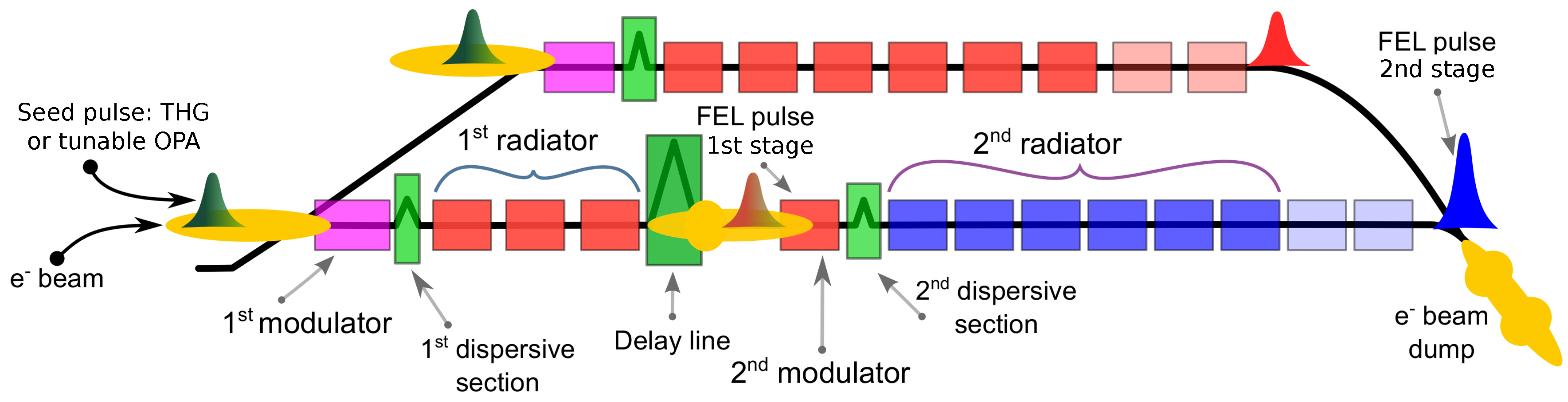
2.1. FERMI FEL-2

FERMI is a FEL user facility. It hosts two separate FEL lines (Figure 1) based on the external seeding technique, in order to deliver spatially and longitudinally coherent pulses in the extreme ultraviolet range with ultrahigh peak brightness, narrow bandwidth spectrum, and stable and ultra short pulse duration in the sub-100-fs range [20,21,29]. The FEL-1 line covers the spectral range 100–20 nm, while the FEL-2 line can reach shorter wavelengths in the range 20–4 nm, thanks to a double stage high gain harmonic generation (HGHG) setup [30] based on the fresh bunch approach [31]. The two lines share the electron beam delivered by the same linear accelerator complex. The electron beam energy can be adjusted from 0.9 to 1.5 GeV. In the case of FEL-2, this enables us to extend the tuning range depending on the required polarization state and wavelength. In this study, the characterisation of the second stage radiation at “long” wavelength, i.e., above 6 nm, were performed at an electron beam energy of 1 GeV, while the measurements below 6 nm were done at an energy of 1.45 GeV. The electron beam parameters used in the experiment are reported in Table 1.
Compared with self-amplified spontaneous emission (SASE) mode, the HGHG scheme uses an external laser to imprint a modulation on the electron beam, which is then amplified and leads to coherent light emission at harmonics of the initial laser frequency. There are two configurations available for the seed laser of FERMI. A seed laser with tunable wavelength is provided by an optical parametric amplifier (OPA) pumped by a Ti:Sapphire laser, or a fixed-wavelength seed laser is obtained by the third harmonic generation (THG) of the Ti:Sapphire laser. The best output pulse energy performance and spectral quality are usually available when the FEL is seeded with the THG seed laser, which is the mode used for the campaign of polarization measurements on FEL-2. The THG seed laser parameters are summarized in Table 2.
On FEL-2, the HGHG double-stage cascade scheme uses the light emitted by a first HGHG FEL to seed a second FEL stage (Figure 1, bottom). The interaction in the second stage is shifted to the head of the electron bunch by means of a magnetic chicane that delays the electron beam. Thus, the radiation of the first stage can seed a fresh portion of the electron beam that has not been affected by the FEL emission in the first stage. The first stage is a replica of the FEL-1 (Figure 1, top) with a reduced number of radiators. It is generally operated in circular polarization in order to obtain the highest energy per pulse necessary to seed the second stage but can also be set to linear horizontal or vertical polarization. The second stage can be tuned to linear horizontal, vertical or circular left or right polarization. As pointed out before, we used two different beam energies in order to extend the tuning range of the FEL. The associated parameters of the undulator chain are reported in Table 3.
In user operation, the light of the first stage is usually filtered out and the transport line of the FEL light is generally optimized for the short wavelengths emitted in the second part of the undulators. Moreover, the transverse profile of the first stage pulse is spoiled by diffraction in the vacuum chamber of the electron beam. Nonetheless, a recent user experiment took advantage of the presence of the first stage pulses in order to perform UV-pump soft-X-ray-probe either with the first or second stage pulse [32]. Another user experiment consisted of a soft-X-ray pump-probe experiment with both the first (pump) and the second (probe) stage [33]. The independent control of the polarization state of the first and second stage is thus of crucial interest for the user community.

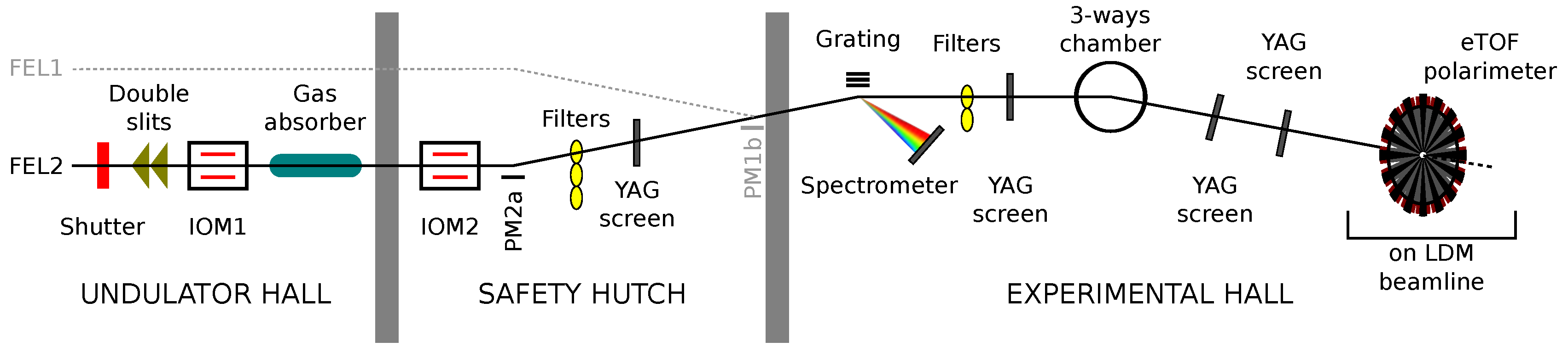
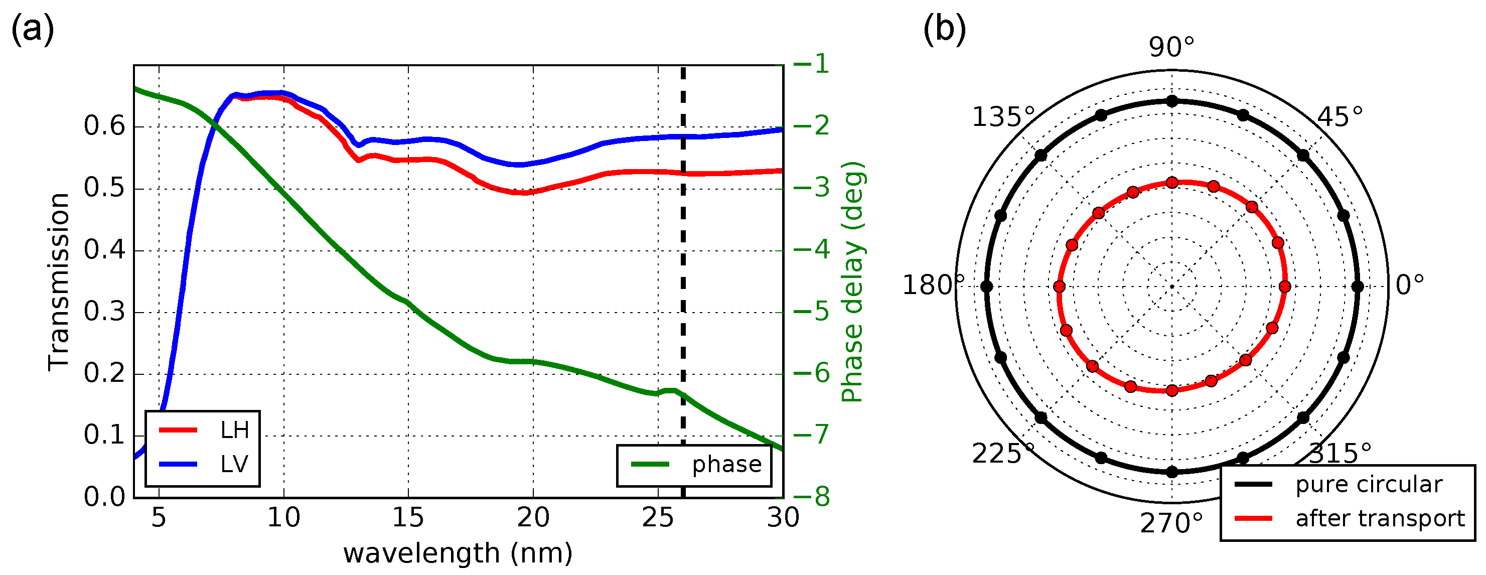
2.2. The Photon Beam Transport

The photon beam paths of the two FEL lines merge in the safety hutch (see Figure 2); photons are then transported to the experimental station through a common set of optics. The photon beam is analyzed before its delivery to the beamline endstations through the PADReS (Photon Analysis, Delivery and Reduction System) section of the machine [34]. Each FEL line has its own noninvasive beam diagnostics and transverse shaping instruments like an intensity monitor, a gas absorber and a set of double slits to adjust the beam aperture. At the end of the safety hutch, either the FEL-1 or the FEL-2 path can be selected by means of the PM1b plane mirror. At the exit of the safety hutch, the FEL spectrum is acquired using the energy spectrometer PRESTO (Pulse-Resolved Energy Spectrometer: Transparent and Online) [35] by diffracting and detecting 2 % of the total intensity of the light. One of three different gratings can be used: the low-energy (LE) grating that covers the range 100–24.8 nm, the high-energy (HE) grating for the 27.6–6.7 nm range, and the super-high-energy (SHE) grating for wavelengths below 12.7 nm. The almost unperturbed photon beam is transported to the desired endstation through the three-way chamber that deflects the beam by means of a switching mirror. The polarimeter used in the experiment was mounted on the Low Density Matter (LDM) endstation [36].
Due to the geometry of the optics transport to the LDM station (four mirrors reflecting in the horizontal plane and two in the vertical plane in the case of FEL-2), the vertical polarization is better transmitted than the horizontal one, especially for wavelengths longer than 10 nm (Figure 3a, red and blue lines). As an example, the ratio between the transmission of vertical and horizontal polarization for a radiation at 26 nm is equal to 1.1. Moreover, the transport optics contribute also to a different phase delay for the horizontal and the vertical polarization (Figure 3a, green line). The difference in transmission and phase delay induce a wavelength-dependent change of ellipticity. Figure 3b shows the corresponding deformation of the photoelectron angular distribution for circularly polarized light at 26 nm (see Section 2.3 for details on the photoelectron angular distribution).
In order to control the intensity ratio between the first and second stage, a series of filters (Zirconium, Palladium) can be inserted along the transport, in particular to suppress the radiation from the first stage. A gas cell can also be filled with diverse atomic gases to attenuate either the radiation of the first or second stage, depending on the selected gas (Nitrogen, Helium, Neon). A double slit system can be used as a spatial filter for the first stage light, which is more divergent than that of the second stage.

2.3. The Electron Time-Of-Flight Polarimeter

Several established methods exist to characterize the polarization of an undulator [27,37,38,39,40]. In our previous work [28], we extensively compared the merits of different instruments, namely, an optical, a fluorescence, and an eTOF polarimeter. We preferred the latter instrument over the other two because it permits non-invasive, single-shot measurements over a large wavelength range. In the case of FERMI FEL-2, the use of the eTOF polarimeter allows for simultaneous measurements of the two FEL stage emissions.
The eTOF polarimeter designed, manufactured and assembled by DESY in Hamburg, Germany, is a 16-channel electron time-of-flight (eTOF) spectrometer (Figure 2). The device is generally mounted such that it measures photoelectrons emitted in the plane perpendicular to the beam propagation direction [41,42]. The spectrometers allow us to detect the angular distribution of the photoelectrons that are emitted by the ionizing radiation of a target gas (here, He and Ne). In our case, the kinetic energies of the detected electrons range from about 0–300 eV. The angular distribution depends on the degree of linear polarization and on the particular subshell of an atomic gas target that is ionized. In the dipole approximation, the photoelectron angular distribution (PAD) can be described by the following expression:
P θ = A 1 + β 2 4 1 + 3 P lin cos 2 θ - ψ ,
where A is the intensity, P lin the degree of linear polarization, ψ the direction of the linear polarization and θ the angle of detection. Notice that A 0 , 0 P lin 1 and - π ψ π . β 2 describes the angular anisotropy parameter. For the case of He atoms, β 2 is equal to 2, which leads, in the case of completely linear, horizontal polarized radiation, to an emission pattern with lobes in the horizontal direction and a node in the vertical direction.
The degree of circular polarization can be deduced upon assuming that the radiation is fully polarized. This assumption is reasonable in the case of FERMI FELs since it has already been demonstrated, by measuring the linear polarization, that the degree of polarization is clearly above 90% [28]. The degree of circular polarization ( P circ ), without distinction between left and right, can be evaluated by the formula P circ = 1 - P lin 2 .
The efficiency and the relative transmission of the 16 detectors were normalized by analyzing the distribution of a Ne gas target ionized at a wavelength of 43.7 nm, where β 2 = 0 [43], i.e., the PAD is isotropic regardless of the state of light polarization. Only the first stage of FEL-2 was used for the calibration, in linear horizontal polarization at 43.7 nm with an energy per pulse of ∼2 μ J to avoid saturation effects in the detectors.
Figure 4 shows a typical signal obtained from the eTOF polarimeter using He as gas target. The 16 spectral traces (Figure 4a) are composed of two photoelectron peaks. The calibration from time-of-flight t to photon energy E ph was done by fitting the FEL peaks to the formula E ph = ( a / ( t - t 0 ) ) 2 + b . This calibration allows for identifying the emission from the first and second stage but does not enter in the data processing. The photoelectron peak at long time-of-flight corresponds to the emission from the first stage, while the peak at short time-of-flight corresponds to the emission from the second stage. The analysis of the eTOF signals allows for reconstructing the angular distribution of the photoelectrons ionized by the two-color polarized FEL pulses (Figure 4b). The single-shot PAD is obtained by integrating numerically the area of the emission line of each detector. The intensity of the FEL pulses was adjusted in order to avoid saturation on the detectors and signal ringing, which can introduce cross-talk between the two stage signals. By fitting the single-shot PAD with Equation (1), one can determine the characteristics of the polarized light. In Figure 4, the two colors have different PAD patterns. Here, the first stage was set to circular right polarization while the second stage was set to linear horizontal one. For horiziontally polarized light, one can see the nodes along the vertical direction ( 90 , 270 ) in the photoelectron distribution.

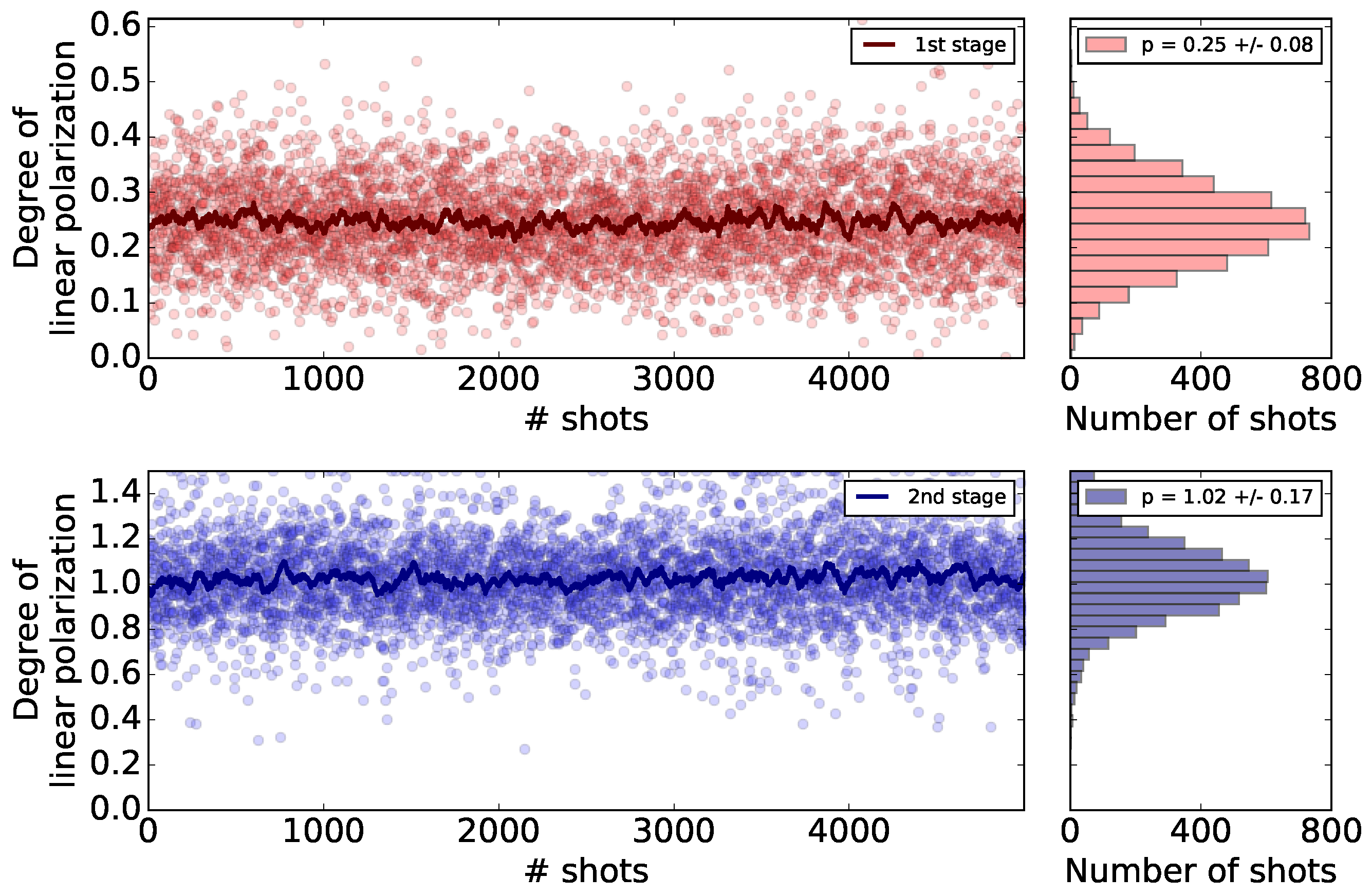
3. Results and Discussion

Polarization measurements were carried out at the LDM beamline for various undulators configurations. Thanks to the parallel detection of electrons of all kinetic energies in the time-of-flight spectrometers and the single-shot capability of the eTOF polarimeter, it has been possible to measure simultaneously the polarization of the first and second stage of FEL-2 (Figure 5). A full set of acquisitions took around 10 min, which corresponds to 6000 FEL pulses. For the reported data, the first stage was tuned at the tenth and eleventh harmonic of the seed laser while the second stage was tuned at the fourth, fifth and sixth harmonic of the first stage. Figure 5 presents polarization data in a typical configuration of operation of FEL-2 where the first and second stage radiators are tuned to a different polarization state. The first stage (h10) produced circularly polarized light while the second stage (h10 × 5) emitted linearly horizontal polarized light. The eTOF polarimeter permits, for single shot analysis only, to measure the degree of linear polarization ( P lin ). Assuming a fully polarized light (with no unpolarized contributions), one can deduce the degree of circular polarization ( P circ ) of the first stage to be equal to 0.96 .
In the case of FEL-2, the light emitted from the first stage is used as a seed for the second stage. Inasmuch as the first and the second stage can be detected simultaneously in the eTOF polarimeter, we can study the influence of the first stage emission on the polarization state of the second stage (Figure 6). The intensity of both the first and second stage, inside the polarimeter (i.e., after transport to LDM through the PADReS line), is clearly correlated as expected (Figure 6a). From the data in Figure 6b, one can see that the degree of polarization of the second stage is independent of the polarization state of the first stage. Moreover, as shown in Figure 6c,d, the degree of polarization of the second stage is also insensitive to the intensity of the first stage seed as well as to the FEL output power (i.e., intensity of the second stage emission). As expected, the absence of correlation between the degree of polarization of the two stages and the intensities confirms that two polarizations are independent and can be tuned separately. Results also suggest, as already reported [19,28], that measured polarization fluctuations are mostly related to instrumental statistical uncertainty of the polarimeter and not associated with a real fluctuation of the degree of polarization.
One feature of FERMI FEL resides in the used undulator type, the variable polarization undulators of Apple-II type [22], which permits switching from one state to another state of polarization in a fast and reliable way. We report, in Figure 7, measurements of the direction of polarization with the radiators of the second stage tuned in linear horizontal (LH) and linear vertical (LV) polarization mode. The trend of the moving averages show a good stability of the direction of polarization and low single shot fluctuations.
The complete results of polarization measurements are summarized in Table 4. The Stokes parameters S 1 and S 2 are extracted from the degree and the direction of the linear polarization using trigonometric relationships, while S 3 is deduced assuming a completely polarized light. The results indicate a high degree of polarization ( > 95 % ) for almost all the polarizations and wavelengths studied. Figure 8 presents the measured Stokes parameters in the case of circularly polarized light, combined with the predicted Stokes parameters including beam-line-transport and contamination effects. In the case of circularly polarized light, we observe a non-negligible ellipticity that can be explained by the asymmetric transmission of the transport optics between LH and LV polarizations (Figure 3). The effect is particularly noticeable for “long” wavelengths. The calculation of the Stokes parameters neglects the unpolarized component of light that might be attributed to transport optics with residual roughness and diffraction effects. The carbon contamination can alter the transmission ratio between horizontal and vertical polarization [44] more than what was predicted from uncontaminated optics and reported in Figure 3a. The off-axis emission may also contribute to the degradation of the degree of polarization.

4. Conclusions

We have presented a study of the FEL polarization produced by FERMI FEL-2 in the soft X ray domain, for a large range of wavelengths and different undulator settings. The characterization of the second stage of FERMI FEL-2, together with the first stage, has been achieved. Our results highlight a high quality of the FEL polarization. We have shown that the polarization state of the two stages may be controlled and adjusted separately by changing the undulator polarization settings. These results pave the way for a new class of circular dichroism experiments based on two polarized beams. In the case of circular FEL polarization, a small ellipticity has been measured and may be explained, in part, by the asymmetry in the transmission of the s and p polarization along the photon transport. A fine tuning of the undulator settings could be used to compensate the effect of beamline transmission, thereby eliminating the spurious amount of linear polarization, in order to provide FEL radiation that is completely circularly polarized.

Acknowledgments

The authors are grateful to the entire FERMI team for the valuable support and operation of the machine.

Author Contributions

E.R., E.A., E.F. and G.P. coordinated the experiment. A.B., L.Gl., G.H., F.S., J.S., I.S. and J.V. designed, manufactured and assembled the eTOF polarimeter. C.C., M.C., R.C. and P.F. installed the polarimeter on LDM. L.R., C.S. and M.Z. transported and focused the soft X-ray beam in the polarimeter. C.S. performed the theoretical calculation of the Stokes parameters. E.R., E.A., S.D.M., B.D., E.F., D.G., G.P. and L.Gi. optimized the FEL during the preparation and execution of the experiment. E.R., E.F., E.A. and G.P. acquired the FEL polarization data and E.R. carried out data analysis, with contribution from G.H.. E.R. wrote the manuscript with contributions from all authors.

Conflicts of Interest

The authors declare no conflict of interest.

References

  1. Eisebitt, S.; Luning, J.; Schlotter, W.F.; Lorgen, M.; Hellwig, O.; Eberhardt, W.; Stohr, J. Lensless imaging of magnetic nanostructures by X-ray spectro-holography. Nature 2004, 432, 885–888. [Google Scholar] [CrossRef] [PubMed]
  2. Boeglin, C.; Beaurepaire, E.; Halte, V.; Lopez-Flores, V.; Stamm, C.; Pontius, N.; Durr, H.A.; Bigot, J.Y. Distinguishing the ultrafast dynamics of spin and orbital moments in solids. Nature 2010, 465, 458–461. [Google Scholar] [CrossRef] [PubMed]
  3. Von Korff Schmising, C.; Pfau, B.; Schneider, M.; Günther, C.M.; Giovannella, M.; Perron, J.; Vodungbo, B.; Müller, L.; Capotondi, F.; Pedersoli, E.; et al. Imaging Ultrafast Demagnetization Dynamics after a Spatially Localized Optical Excitation. Phys. Rev. Lett. 2014, 112, 217203. [Google Scholar] [CrossRef]
  4. Garcia, G.A.; Nahon, L.; Lebech, M.; Houver, J.C.; Dowek, D.; Powis, I. Circular dichroism in the photoelectron angular distribution from randomly oriented enantiomers of camphor. J. Chem. Phys. 2003, 119, 8781–8784. [Google Scholar] [CrossRef]
  5. Janssen, M.H.M.; Powis, I. Detecting chirality in molecules by imaging photoelectron circular dichroism. Phys. Chem. Chem. Phys. 2014, 16, 856–871. [Google Scholar] [CrossRef] [PubMed]
  6. Desiderio, D.; Difonzo, S.; Diviacco, B.; Jark, W.; Krempasky, J.; Krempaska, R.; Lama, F.; Luce, M.; Mertins, H.C.; Placentini, M.; et al. The ELETTRA circular polarization beamline and electromagnetic elliptical wiggler insertion device. Synchrotron Radiat. News 1999, 12, 34–38. [Google Scholar] [CrossRef]
  7. Bahrdt, J.; Frentrup, W.; Gaupp, A.; Scheer, M.; Gudat, W.; Ingold, G.; Sasaki, S. Elliptically polarizing insertion devices at BESSY II. Nucl. Instrum. Methods Phys. Res. Sect. A 2001, 467–468, 21–29. [Google Scholar] [CrossRef]
  8. Benabderrahmane, C.; Berteaud, P.; Briquez, F.; Couprie, M.E.; Chubar, O.; Dubois, L.; Filhol, J.M.; Girault, M.; Level, M.P.; Marcouillé, O.; et al. First SOLEIL insertion devices are ready to produce photons for users. Nucl. Instrum. Methods Phys. Res. Sect. A 2007, 575, 33–37. [Google Scholar] [CrossRef]
  9. Nahon, L.; de Oliveira, N.; Garcia, G.A.; Gil, J.F.; Pilette, B.; Marcouillé, O.; Lagarde, B.; Polack, F. DESIRS: A state-of-the-art VUV beamline featuring high resolution and variable polarization for spectroscopy and dichroism at SOLEIL. J. Synchrotron Radiat. 2012, 19, 508–520. [Google Scholar] [CrossRef] [PubMed]
  10. Wang, H.; Bencok, P.; Steadman, P.; Longhi, E.; Zhu, J.; Wang, Z. Complete polarization analysis of an APPLE II undulator using a soft X-ray polarimeter. J. Synchrotron Radiat. 2012, 19, 944–948. [Google Scholar] [CrossRef] [PubMed]
  11. Viefhaus, J.; Scholz, F.; Deinert, S.; Glaser, L.; Ilchen, M.; Seltmann, J.; Walter, P.; Siewert, F. The Variable Polarization XUV Beamline P04 at PETRA III: Optics, mechanics and their performance. Nucl. Instrum. Methods Phys. Res. Sect. A 2013, 710, 151–154. [Google Scholar] [CrossRef]
  12. Vodungbo, B.; Sardinha, A.B.; Gautier, J.; Lambert, G.; Valentin, C.; Lozano, M.; Iaquaniello, G.; Delmotte, F.; Sebban, S.; Lüning, J.; et al. Polarization control of high order harmonics in the EUV photon energy range. Opt. Express 2011, 19, 4346–4356. [Google Scholar] [CrossRef] [PubMed]
  13. Fleischer, A.; Kfir, O.; Diskin, T.; Sidorenko, P.; Cohen, O. Spin angular momentum and tunable polarization in high-harmonic generation. Nat. Photon. 2014, 8, 543–549. [Google Scholar] [CrossRef]
  14. Lambert, G.; Vodungbo, B.; Gautier, J.; Mahieu, B.; Malka, V.; Sebban, S.; Zeitoun, P.; Luning, J.; Perron, J.; Andreev, A.; et al. Towards enabling femtosecond helicity-dependent spectroscopy with high-harmonic sources. Nat. Commun. 2015, 6, 6167. [Google Scholar] [CrossRef] [PubMed]
  15. Pfau, B.; Günther, C.M.; Könnecke, R.; Guehrs, E.; Hellwig, O.; Schlotter, W.F.; Eisebitt, S. Magnetic imaging at linearly polarized X-ray sources. Opt. Express 2010, 18, 13608–13615. [Google Scholar] [CrossRef] [PubMed]
  16. Wang, T.; Zhu, D.; Wu, B.; Graves, C.; Schaffert, S.; Rander, T.; Müller, L.; Vodungbo, B.; Baumier, C.; Bernstein, D.P.; et al. Femtosecond Single-Shot Imaging of Nanoscale Ferromagnetic Order in Co/Pd Multilayers using resonant X-ray holography. Phys. Rev. Lett. 2012, 108, 267403. [Google Scholar] [CrossRef] [PubMed]
  17. Kim, K.J. Circular polarization with crossed-planar undulators in high-gain FELs. Nucl. Instrum. Methods Phys. Res. Sect. A 2000, 445, 329–332. [Google Scholar] [CrossRef]
  18. Deng, H.; Zhang, T.; Feng, L.; Feng, C.; Liu, B.; Wang, X.; Lan, T.; Wang, G.; Zhang, W.; Liu, X.; et al. Polarization switching demonstration using crossed-planar undulators in a seeded free-electron laser. Phys. Rev. Spec. Top. Accel. Beams 2014, 17, 020704. [Google Scholar] [CrossRef]
  19. Ferrari, E.; Allaria, E.; Buck, J.; De Ninno, G.; Diviacco, B.; Gauthier, D.; Giannessi, L.; Glaser, L.; Huang, Z.; Ilchen, M.; et al. Single Shot Polarization Characterization of XUV FEL Pulses from Crossed Polarized Undulators. Sci. Rep. 2015, 5, 13531. [Google Scholar] [CrossRef] [PubMed]
  20. Allaria, E.; Appio, R.; Badano, L.; Barletta, W.A.; Bassanese, S.; Biedron, S.G.; Borga, A.; Busetto, E.; Castronovo, D.; Cinquegrana, P.; et al. Highly coherent and stable pulses from the FERMI seeded free-electron laser in the extreme ultraviolet. Nat. Photon. 2012, 6, 699–704. [Google Scholar] [CrossRef]
  21. Allaria, E.; Castronovo, D.; Cinquegrana, P.; Craievich, P.; Dal Forno, M.; Danailov, M.B.; D’Auria, G.; Demidovich, A.; De Ninno, G.; Di Mitri, S.; et al. Two-stage seeded soft-X-ray free-electron laser. Nat. Photon. 2013, 7, 913–918. [Google Scholar] [CrossRef]
  22. Sasaki, S. Analyses for a planar variably-polarizing undulator. Nucl. Instrum. Methods Phys. Res. Sect. A 1994, 347, 83–86. [Google Scholar] [CrossRef]
  23. Temnykh, A.B. Delta undulator for Cornell energy recovery linac. Phys. Rev. Spec. Top. Accel. Beams 2008, 11, 120702. [Google Scholar] [CrossRef]
  24. Lutman, A.A.; MacArthur, J.P.; Ilchen, M.; Lindahl, A.O.; Buck, J.; Coffee, R.N.; Dakovski, G.L.; Dammann, L.; Ding, Y.; Dürr, H.A.; et al. Polarization control in an X-ray free-electron laser. Nat. Photon. 2016, 10, 468–472. [Google Scholar] [CrossRef]
  25. Capotondi, F.; Pedersoli, E.; Mahne, N.; Menk, R.H.; Passos, G.; Raimondi, L.; Svetina, C.; Sandrin, G.; Zangrando, M.; Kiskinova, M.; et al. Coherent imaging using seeded free-electron laser pulses with variable polarization: First results and research opportunities. Rev. Sci. Instrum. 2013, 84, 051301. [Google Scholar] [CrossRef] [PubMed]
  26. Müller, L.; Schleitzer, S.; Gutt, C.; Pfau, B.; Schaffert, S.; Geilhufe, J.; von Korff Schmising, C.; Schneider, M.; Günther, C.M.; Büttner, F.; et al. Ultrafast Dynamics of Magnetic Domain Structures Probed by Coherent Free-Electron Laser Light. Synchrotron Radiat. News 2013, 26, 27–32. [Google Scholar] [CrossRef]
  27. Mazza, T.; Ilchen, M.; Rafipoor, A.J.; Callegari, C.; Finetti, P.; Plekan, O.; Prince, K.C.; Richter, R.; Danailov, M.B.; Demidovich, A.; et al. Determining the polarization state of an extreme ultraviolet free-electron laser beam using atomic circular dichroism. Nat. Commun. 2014, 5, 3648. [Google Scholar] [CrossRef] [PubMed]
  28. Allaria, E.; Diviacco, B.; Callegari, C.; Finetti, P.; Mahieu, B.; Viefhaus, J.; Zangrando, M.; De Ninno, G.; Lambert, G.; Ferrari, E.; et al. Control of the Polarization of a Vacuum-Ultraviolet, High-Gain, Free-Electron Laser. Phys. Rev. X 2014, 4, 041040. [Google Scholar] [CrossRef]
  29. Allaria, E.; Badano, L.; Bassanese, S.; Capotondi, F.; Castronovo, D.; Cinquegrana, P.; Danailov, M.B.; D’Auria, G.; Demidovich, A.; De Monte, R.; et al. The FERMI free-electron lasers. J. Synchrotron Radiat. 2015, 22, 485–491. [Google Scholar] [CrossRef] [PubMed]
  30. Yu, L.H. Generation of intense uv radiation by subharmonically seeded single-pass free-electron lasers. Phys. Rev. A 1991, 44, 5178–5193. [Google Scholar] [CrossRef] [PubMed]
  31. Ben-Zvi, I.; Yang, K.; Yu, L. The “fresh-bunch” technique in FELS. Nucl. Instrum. Methods Phys. Res. Sect. A 1992, 318, 726–729. [Google Scholar] [CrossRef]
  32. Piseri, P.; Dipartimento di Fisica, Università degli Studi di Milano, Milano, Italy. Private communication, 2016.
  33. Fennel, T.; Institute of Physics, University of Rostock, Rostock, Germany. Private communication, 2016.
  34. Zangrando, M.; Cocco, D.; Fava, C.; Gerusina, S.; Gobessi, R.; Mahne, N.; Mazzucco, E.; Raimondi, L.; Rumiz, L.; Svetina, C. Recent results of PADReS, the Photon Analysis Delivery and REduction System, from the FERMI FEL commissioning and user operations. J. Synchrotron Radiat. 2015, 22, 565–570. [Google Scholar] [CrossRef] [PubMed]
  35. Svetina, C.; Cocco, D.; Mahne, N.; Raimondi, L.; Ferrari, E.; Zangrando, M. PRESTO, the on-line photon energy spectrometer at FERMI: Design, features and commissioning results. J. Synchrotron Radiat. 2016, 23, 35–42. [Google Scholar] [CrossRef] [PubMed]
  36. Svetina, C.; Grazioli, C.; Mahne, N.; Raimondi, L.; Fava, C.; Zangrando, M.; Gerusina, S.; Alagia, M.; Avaldi, L.; Cautero, G.; et al. The Low Density Matter (LDM) beamline at FERMI: Optical layout and first commissioning. J. Synchrotron Radiat. 2015, 22, 538–543. [Google Scholar] [CrossRef] [PubMed]
  37. Schäfers, F.; Mertins, H.C.; Gaupp, A.; Gudat, W.; Mertin, M.; Packe, I.; Schmolla, F.; Fonzo, S.D.; Soullié, G.; Jark, W.; et al. Soft-X-ray polarimeter with multilayer optics: Complete analysis of the polarization state of light. Appl. Opt. 1999, 38, 4074–4088. [Google Scholar] [CrossRef] [PubMed]
  38. Wang, H.; Dhesi, S.S.; Maccherozzi, F.; Cavill, S.; Shepherd, E.; Yuan, F.; Deshmukh, R.; Scott, S.; van der Laan, G.; Sawhney, K.J.S. High-precision soft X-ray polarimeter at Diamond Light Source. Rev. Sci. Instrum. 2011, 82, 123301. [Google Scholar] [CrossRef] [PubMed]
  39. Grizolli, W.; Laksman, J.; Hennies, F.; Jensen, B.N.; Nyholm, R.; Sankari, R. Multilayer based soft-X-ray polarimeter at MAX IV Laboratory. Rev. Sci. Instrum. 2016, 87, 025102. [Google Scholar] [CrossRef] [PubMed]
  40. Latimer, C.; MacDonald, M.; Finetti, P. A new method for polarization analysis in the VUV. J. Electron Spectrosc. Relat. Phenom. 1999, 101, 875–878. [Google Scholar] [CrossRef]
  41. Ilchen, M.; Glaser, L.; Scholz, F.; Walter, P.; Deinert, S.; Rothkirch, A.; Seltmann, J.; Viefhaus, J.; Decleva, P.; Langer, B.; et al. Angular Momentum Sensitive Two-Center Interference. Phys. Rev. Lett. 2014, 112, 023001. [Google Scholar] [CrossRef] [PubMed]
  42. Hartmann, G.; Lindahl, A.O.; Knie, A.; Hartmann, N.; Lutman, A.A.; MacArthur, J.P.; Shevchuk, I.; Buck, J.; Galler, A.; Glownia, J.M.; et al. Circular dichroism measurements at an X-ray free-electron laser with polarization control. Rev. Sci. Instrum. 2016, 87, 083113. [Google Scholar] [CrossRef] [PubMed]
  43. Codling, K.; Houlgate, R.G.; West, J.B.; Woodruff, P.R. Angular distribution and photoionization measurements on the 2p and 2s electrons in neon. J. Phys. B Atom. Mol. Phys. 1976, 9, L83. [Google Scholar] [CrossRef]
  44. Yao-Leclerc, I.; Brochet, S.; Chauvet, C.; De Oliveira, N.; Duval, J.P.; Gil, J.F.; Kubsky, S.; Lagarde, B.; Nahon, L.; Nicolas, F.; et al. Handling the carbon contamination issue at SOLEIL. Proc. SPIE 2011, 8077, 807712. [Google Scholar]
Figure 1. FERMI FELs layout: FEL-1 single-stage HGHG configuration (top) and FEL-2 double-stage cascaded HGHG configuration (bottom).
Photonics 04 00029 g001
Figure 2. Schematic layout of the PADReS system to transport the light from FEL-2 to the LDM endstation where the eTOF polarimeter is installed. (IOM: ionization monitor, PM: plane mirror, YAG: Yttrium aluminium garnet).
Photonics 04 00029 g002
Figure 3. (a) calculated transmission of the LDM beamline optics for the FEL-2 line, for the horizontal linear polarization (red) and the vertical linear polarization (blue) [36] and simulated phase delay between vertical and horizontal polarization (green); (b) predicted photoelectron angular distribution in the case of a perfect circular polarization (black) and including the effect of the optical transport system (red) at 26 nm (dashed line in a).
Photonics 04 00029 g003
Figure 4. (a) photon energy spectra from the 16 channels of the eTOF polarimeter (average over 50 shots). The peak around 200 (arb. units) along the time-of-flight axis corresponds to the emission from the first stage and the peak around 100 (arb. units) corresponds to the second stage emission; (b) processed photon angular distribution of the first stage (red) and the second stage (blue) radiation. The dashed curves are single shot PADs while the solid line is an average over 50 shots. The lines are results from the fitting of data (points) with Equation (1).
Photonics 04 00029 g004
Figure 5. Degree of linear polarization P lin of the first stage (red) and of the second stage (blue). The undulators of the first stage were tuned in circular right polarization at 26 . 1 nm and the second stage was tuned in linear horizontal polarization at 5 . 22 nm. The deduced degree of circular polarization is P circ = 0 . 96 . The lines represent the moving average over 50 shots.
Photonics 04 00029 g005
Figure 6. Correlation between first and second stage emission: intensity inside the eTOF polarimeter of the second stage in function of the first stage (a); degree of linear polarization of the second stage as a function of the first stage (b); and degree of linear polarization of the second stage in function of the intensity of the first (c) and the second (d) stage. Same data as in Figure 5. (blue: experimental data, red: linear regression).
Photonics 04 00029 g006
Figure 7. Direction of polarization ψ of the second stage in the case of linear horizontal polarized light (red) and linear vertical polarized light (blue) at 5 . 22 nm. The lines represent the moving average over 50 shots.
Photonics 04 00029 g007
Figure 8. Impact of the LDM transport optics on the Stokes parameters (red = S 1 / S 0 , blue = S 2 / S 0 and green = S 3 / S 0 ) for a circularly polarized light. (dashed lines: predicted Stokes parameters; points: experimental data).
Photonics 04 00029 g008
Table 1. Electron beam parameters used in the experiment.
ParameterValueUnit
Energy1.0/1.45GeV
Slice energy spread (rms)150keV
Slice transverse normalized emittance∼1.5mm.mrad
Peak current650A
Average beam transverse size125 μ m
 in the undulator (rms)
Electron beam magnetic delay line260fs
Repetition rate10Hz
Table 2. Third harmonic generation (THG) seed laser parameters used in the experiment.
ParameterValueUnit
Wavelength261.5nm
Bandwidth (FWHM)1.3nm
Pulse duration (FWHM)135fs
Available energy per pulse≤40 μ J
Average beam size400 μ m
 in the modulator (rms)
Table 3. Main parameters of the FERMI FEL-2 undulators. The tuning ranges are given for an electron beam energy between 1.0 and 1.5 GeV. The polarization states are abbreviated as LH: linear horizontal, LV: linear vertical, CR: circular right, CL: circular left.
1st Stage Modulator1st Stage Radiatorsand 2nd Stage Modulator2nd Stage Radiators
Magnetic period (mm)1005535
Tuning range (nm)300–200114–2018–4
Number of periods304266
Number of segments13 + 16
PolarizationLHLH, LV, CR, CLLH, LV, CR, CL
Table 4. Summary of the polarization measurements for various configurations of FEL-2 and deduced Stokes parameters S 1 , S 2 and S 3 .
Wavelength (nm)FEL Polarization P lin ψ ( ) S 1 / S 0 S 2 / S 0 S 3 / S 0
26.1 Circular right 0.27 ± 0.08 93.3 ± 12.0 - 0.24 - 0.03 0.96
23.73 Circular right 0.25 ± 0.13 92.5 ± 28.0 - 0.17 - 0.03 0.96
10.88 Circular right 0.31 ± 0.09 75.0 ± 10.0 - 0.25 0.15 0.95
8.7 Circular right 0.34 ± 0.09 72.6 ± 9.4 - 0.26 0.18 0.94
5.93 Circular right 0.20 ± 0.09 88.3 ± 19.9 - 0.17 0.01 0.97
5.22 Circular right 0.26 ± 0.12 87.3 ± 23.3 - 0.20 0.02 0.96
10.88 Linear horizontal 0.99 ± 0.10 6.8 ± 3.7 0.95 0.23 0.37
8.7 Linear horizontal 1.00 ± 0.12 7.0 ± 4.6 0.95 0.24 0.40
5.22 Linear horizontal 1.01 ± 0.16 2.2 ± 6.2 0.99 0.08 0.44
8.7 Linear vertical 0.99 ± 0.11 84.7 ± 4.0 - 0.96 0.18 0.39
5.22 Linear vertical 0.96 ± 0.15 89.9 ± 5.1 - 0.95 0.00 0.46

