Review

Three-Dimensional Carbon Nanostructures for Advanced Lithium-Ion Batteries

1
Department of Materials Science and Engineering, University of North Texas, North Texas Discovery Park 3940 North Elm St. Suite E-132, Denton, TX 76207, USA
2
Vehicle Technologies Office, Office of Energy Efficiency and Renewable Energy, U.S. Department of Energy, 1000 Independence Ave., SW, Washington, DC 20585, USA
3
Department of Mechanical and Energy Engineering, University of North Texas, North Texas Discovery Park 3940 North Elm St. Suite E-132, Denton, TX 76207, USA
*
Author to whom correspondence should be addressed.
These authors contributed equally to this work.
Submission received: 29 July 2016 / Revised: 1 October 2016 / Accepted: 13 October 2016 / Published: 26 October 2016
(This article belongs to the Special Issue Batteries: Recent Advances in Carbon Materials)

Abstract

:
Carbon nanostructural materials have gained the spotlight as promising anode materials for energy storage; they exhibit unique physico-chemical properties such as large surface area, short Li+ ion diffusion length, and high electrical conductivity, in addition to their long-term stability. However, carbon-nanostructured materials have issues with low areal and volumetric densities for the practical applications in electric vehicles, portable electronics, and power grid systems, which demand higher energy and power densities. One approach to overcoming these issues is to design and apply a three-dimensional (3D) electrode accommodating a larger loading amount of active anode materials while facilitating Li+ ion diffusion. Furthermore, 3D nanocarbon frameworks can impart a conducting pathway and structural buffer to high-capacity non-carbon nanomaterials, which results in enhanced Li+ ion storage capacity. In this paper, we review our recent progress on the design and fabrication of 3D carbon nanostructures, their performance in Li-ion batteries (LIBs), and their implementation into large-scale, lightweight, and flexible LIBs.

Graphical Abstract

1. Introduction

Novel, economical, and sustainable energy storage systems have emerged as a response to the needs of modern society and rising ecological concerns [1]. The excellent electrochemical properties and unique designs of the electrode materials in Li-ion batteries (LIBs) make them strong contenders for the development of large-scale, advanced transportation (e.g., electric vehicles) and smart grid applications [2]. The commercial use of graphitic carbon-based anode materials is justified by their relatively low cost, excellent structural integrity for the insertion and extraction of Li+ ions, safety (free from Li dendrite formation), and formation of a protective passivation layer against many electrolytes (i.e., solid electrolyte interphase (SEI)) [3]. Nevertheless, a low specific capacity of graphite (372 mAh·g−1, the stoichiometric formula—LiC6) is a critical limitation [4]; as a result, they potentially hinder the advance of large-scale energy storage systems that demand high energy and power densities. Thus, carbon nanostructures including carbon nanotubes, graphene, and nanoporous carbon have gained a fair amount of attention due to their superior specific capacities over graphite. Such a superior capacity is largely attributed to the unique features of carbon nanostructures, including high surface area for large Li+ ion accommodation, exceptional electrical and thermal conductivities, structural flexibility, short Li+ ion diffusion length, and broad electrochemical window [4,5,6,7,8].
There have been numerous reports on the LIB performance of nanostructured carbons (e.g., carbon nanotubes (CNTs), graphene, and nanoporous carbon) with diverse structures and morphologies through various synthetic methods. CNTs have been verified as promising anode nanomaterials due to their excellent electrochemical properties [9,10,11,12,13,14,15,16,17,18,19,20,21]. Our research team recently reported exceptionally high and stable reversible capacities of ~900 mAh·g−1 at 372 mA·g−1 or 1C (time for complete discharge in reciprocal hours) from CNTs directly grown on a Cu substrate [22]; we also demonstrated that the atomic layer deposition (ALD) alumina (Al2O3) coated CNTs on Cu showed a specific capacity of ~1100 mAh·g−1 [23]. Furthermore, graphene [6,24,25,26] and nanoporous carbon [27,28] based anode materials have been widely investigated to enhance Li+ ion intercalation capability.
However, there are still technical challenges remaining to be overcome in the practical application of carbon nanostructures to commercial products [29], including: (1) most of the reported carbon nanostructures with high specific capacity are dimensionally limited to thin-film scale, which is unsuitable for use in large-scale LIBs; (2) carbon nanostructures have an intrinsically low bulk density [30] (most nanomaterial-based electroactive materials show a bulk density of less than 1 g·cm−3, lower than the commercial-grade graphite (0.35~0.9 g·cm−3) [31,32]); the low bulk density results in low volumetric capacity, which is inadequate for large-scale energy storage systems [33]. To circumvent the aforementioned limitations, design of 3D carbon nanostructure is one of the most viable approaches to accommodating the large loading amounts of nanocarbon-based electroactive materials. High loading amounts of carbon nanomaterials result in high capacities and a large surface area for the large-scale integration [34]. In addition, the nanoscale porous 3D structure is suited to facilitate Li+ ion and electron charge transfer through the electrolyte and bulk electrode into and from the electroactive materials [35]. Pioneering efforts have been made to design the following substrate architectures: a self-assembled 3D bicontinuous nanoarchitecture [35,36], carbon papers [37], aluminum nanorods [38], nanoporous nickel [39], copper (Cu) pillar array [40], stainless steel mesh [41], and polymer scaffold [42].
In a previous report [33], we demonstrated a mathematical model to calculate the surface area of the 3D Cu mesh structure, which suggests that the surface area increases proportionally to the structure thickness and is optimized at the intermediate hole size (Figure 1). The detailed mathematical calculation may be referred to in our past publication (see Supplementary Information, [33]). Although we applied the 3D cuboid structure to justify the dependence of the surface area on both thickness and hole size, a similar trend would be observed in other 3D structures with various hole morphologies such as circular and triangular when viewed from above. In this model, a 3D Cu mesh with 50 µm thickness and 65 µm hole size corresponds to a nearly 60% increase in surface area, normalized by its 2D Cu counterpart. In contrast, CNTs grown directly on a 3D Cu mesh with the same dimensions had an areal density of ~2.8 mg·cm−2, which is ~400% higher than its 2D counterpart. The slight discrepancy between the theoretical calculations and empirical results could be attributed to the effect of processing parameters of chemical vapor deposition (CVD) (e.g., temperature and time of CNT growth) on the properties of CNTs (e.g., their diameters, lengths, and densities). As expected, the overall capacities of 3D CNTs were superior to those of 2D CNTs due to their higher surface area, which induces greater Li+ ion accommodation (a detailed discussion will be presented in Section 3.7). Similarly, Cheah et al. demonstrated an anode comprising ALD-coated TiO2 on a 3D aluminum nanorod current collector, which showed a high rate capability and a 10-fold superior areal capacity (0.0112 mAh·cm−2) to the same electroactive materials on a 2D aluminum plate [38]. Gregorczyk et al. fabricated a core/shell anode structure composed of ALD-coated RuO2 on a 3D CNT sponge with a capacity of 806 mAh·g−1, a 50-fold higher areal capacity (1.6 mAh·cm−2) than its planar (2D) RuO2 counterpart [43].
There are some investigations and review articles that cover different facets of carbon nanomaterials for energy applications [4,44,45,46,47]. Here we present the first comprehensive review discussing recently reported 3D hybrid architectures comprising nanocarbon and high-capacity nanomaterials for LIB anodes. We further concentrate on our recent advancements in terms of 3D nanostructured carbon materials for energy storage. The majority of the applications will be presented in the form of LIBs; however, the CNTs–graphene–metal seamless structure (Section 3.5) will be discussed in terms of supercapacitor application. The fabrications and properties of 3D multi-layered CNTs, 3D free-standing CNTs, 3D nanocarbon-based hybrid anodes, and CNTs–graphene–metal seamless composites will be intensively explored. Their promising applications in both LIBs and supercapacitors are then thoroughly investigated, with a focus on flexible device integration. Finally, this review will conclude with a brief discussion of current technical challenges and future directions.

2. Literature Survey

Next-generation Li-ion batteries demand high energy and power densities, which are largely obtained from the high capacity of electroactive materials. The conventional graphite-based anode and metal oxides cathode materials show lower theoretical specific capacities (e.g., LiCoO2 (274 mAh·g−1), LiMn2O4 (148 mAh·g−1), and LiFePO4 (170 mAh·g−1)) compared to silicon (3579 mAh·g−1, Li15Si4) and transition metal oxides (e.g., NiO (718 mAh·g−1), SnO2 (782 mAh·g−1), and Fe2O3 (1007 mAh·g−1)). However, these high-capacity nanomaterials show an insulating nature and structural instability during prolonged charge and discharge cycles. Hence, one approach to tackle these drawbacks is to design a hybrid anode for LIBs by incorporating carbon-based nanomaterials into the high-capacity nanomaterials. In this section, we cover the recent reports on hybrid anodes for LIBs integrated with three main 3D carbon nanomaterials, carbon nanotubes, graphene, and nanoporous carbon. Table 1 shows selected fabrication methods and charge capacities of 3D carbon nanomaterial-based anode structures for LIBs.
Three-dimensional CNTs combined with high-capacity anode materials have been synthesized by various methods; their excellent LIB performance has been demonstrated. Chen et al. fabricated the core/shell anode structure of MWCNT/V2O5 sponge using an ALD method. The anode delivered a stable and high areal capacity of 816 μAh·cm−2 at 1C (1.1 mA·cm−2); the capacity was 450 times higher than that of its planar V2O5 thin film counterpart [50]. Hu et al. synthesized a silicon–carbon nanotube coaxial sponge with an areal density of silicon (8 mg·cm−2); additionally, the 3D carbon nanotube was used for an electrical conducting and structural buffering network for high-capacity Si anode materials. The hybrid anode delivered a specific capacity of 1300 mAh·g−1 for 50 cycles with a cutoff voltage of 0.17–1.0 V at 0.2 C [51]. Hu et al. increased the areal densities of LiFePO4 cathode and Li4Ti5O12 anode materials up to 140–170 mg·cm−2; they were approximately seven to eight times higher than the traditional LIB electrode materials. Furthermore, a full cell with both cathode and anode shows a specific capacity of 140–160 mAh·g−1 for 30 cycles at 0.1C [52]. Q. Xiao et al. created a 3D multi-layered Si/CNT hybrid anode structure by thermal and plasma-enhanced CVD methods. The areal capacity proportionally increased with the number of layers (e.g., 1.25 mAh·cm−2 at four layers); the volumetric capacity of the multilayer Si/CNT composite anode was 595.4 mAh·cm−3, superior to the practical volumetric capacity of commercialized graphite anode (~450 mAh·cm−3); moreover, its theoretical volumetric capacity is 830 mAh·cm−3 [53].
Three-dimensional graphene has been incorporated with high-capacity anode materials through various methods, thus leading to outstanding LIB performance. Li et al. synthesized the 3D graphene/ultra-small SnO2 and Fe2O3 anodes by a two-step method: annealing using ion-exchange resin and then a hydrothermal process. Specific capacities of 474 mAh·g−1 and 448 mAh·g−1 were obtained for SnO2- and Fe2O3-based anodes, respectively, at 10 A·g−1 for 1000 cycles; these values were superior to those of most recently reported SnO2- and Fe2O3-based graphene composite anodes [54]. Yang et al. fabricated 3D nanoporous Fe2O3/Fe3C-graphene heterogeneous thin films by anodization and chemical vapor deposition (CVD) methods, in which multi-layer graphene coated on the 3D thin films served as an electrical conducting agent. The 3D thin film anode showed volumetric and specific capacities of 1650 mAh·cm−3 and ~518 mAh·g−1 at ~6.6C for 1000 cycles, respectively. This anode also showed volumetric and gravimetric energy densities of 2.94 Wh·cm−3 and ~924 Wh·kg−1, respectively, and volumetric and gravimetric power densities of 5.84 W·cm−3 and ~1834 W·kg−1, respectively [55]. Wu et al. prepared porous silicon spheres enclosed by 3D graphene network by using a two-step method of layer-by-layer assembly and in situ magnesiothermic reduction [56]. In their report, the 3D Si–graphene hybrid anode delivered a 300% higher specific capacity (~1300 mAh·g−1) than that of a bare silicon sphere-based anode at 0.05C after 25 cycles. Baskaran et al. synthesized 3D multi-layered graphene/Si–CuO quantum dot anodes by electrophoresis deposition, within which graphene mainly functions as an electrical conducting network for the anode. Furthermore, Cu3Si is formed by the subsequent annealing process; consequently, CuO–Cu3Si serves as a mechanical cushion against the large-volume expansion/contraction of Si during cycling. The composite anode delivers a five-fold higher specific capacity (2869 mAh·g−1) than that of graphene for an initial cycle at 0.5C [57]. Shen et al. fabricated 3D TiO2–graphene–CNT composite anode materials through controlled hydrolysis of tetrabutyl titanate (TBT), in which the CNTs act as an electrically conducting network to facilitate electron transport between the TiO2-anchored graphene layers. Furthermore, CNTs served as mechanical bridges between the graphene layers, which prevented their restack problems, thus leading to the preservation of their high surface area and accelerating the Li+ ion insertion/extraction rate into/from the 3D anode structure. The 3D anode showed a capacity of 93.1 mAh·g−1 at 30C (this value is higher than that of the previously reported graphene-TiO2 hybrid anode materials) and 111.2 mAh·g−1 at 10C after 100 cycles, respectively [58]. Li et al. employed 3D flexible, conducting network of graphene foam loaded with Li4Ti5O12 and LiFePO4 as anode and cathode materials, respectively, by using hydrothermal synthetic method. The 3D electrode-based flexible full LIB was cycled over 100 cycles at 10C with only 4% capacity loss (117 mAh·g−1) and this value surpasses most full LIBs reported in terms of rate capability and cycling performance [59]. Tao et al. employed a sonication method to anchor carnation-like NiO fabricated via a hydrothermal method both onto and into graphene layers by using a modified Hummers method. The 3D hierarchical NiO–graphene hybrid anode exhibited a reversible capacity of 1065 mAh·g−1 (higher than the theoretical capacity of NiO (718 mAh·g−1)) for the 50th cycle at a current density of 200 mA·g−1. Graphene layers largely served as electrical conducting pathways to reduce the polarization of the anode; consequently, they decrease the internal resistance of an LIB cell. Furthermore, graphene layers effectively circumvented the issue with the physical aggregation of NiO by maintaining a steadfast cycling performance and rate capability [60]. As mentioned earlier, 3D carbon nanostructures were employed to create large volumetric and areal capacities for large-scale energy storage systems demanding high values of volumetric and gravimetric energy densities. With respect to other anode configurations, a 3D silicon–carbon composite anode is considered a significant contender to achieve the aforementioned aim. Wang et al. synthesized the 3D graphitic carbon layer conformally deposited on perforated silicon nanowire arrays through a metal-aided chemical etching of silicon wafers and in situ decomposition of methane (CH4) for depositing carbon. Noticeably, they struck a balance between the maximized bulk density of Si nanowires and the necessary porous structures to guard against the strain induced by a large-volume variation (~300%) of Si despite their trade-off relationship. Furthermore, the 3D anode structure exhibited its structural and interfacial stability by maintaining a volumetric capacity of 1500 mAh·cm−3 after 200 cycles; this value was nearly four times higher than those of commercially available graphite and comparable to or even superior to the other reported values of Si-based anodes [61].
Three-dimensional hierarchical nanoporous carbon possesses its exceptional surface area and pore volume to offer more Li+ ion accommodation sites relative to the other carbon nanomaterials. Zhou et al. fabricated 3D ordered mesoporous carbon (CMK-3) with a uniform pore size of 3.9 nm, a Brunauer–Emmer–Teller (BET) surface area of 1030 m2·g−1, and a total pore volume of 0.87 cm3·g−1 by using a sacrificial silica template and thermal carbonization of sucrose. Thanks to the unique nanoscale pore structures leading to such high surface area and pore volume, high capacity was obtained in the range of 850–1100 mAh·g−1 at a current density of 100 mA·g−1 [68]. Hu et al. utilized a sacrificial meso-/macroporous silica-based hard template for the fabrication of a 3D porous carbon replica via the infiltration of the silica template into a mesophase pitch dissolved solution and the subsequent thermal carbonization and silica removal. The 3D porous carbon, consisting of well-interconnected walls with submicron thickness, offers a porosity large enough to maintain a sufficient Li+ diffusion rate while maintaining high electrical conductivity of ~0.1 S·cm−1; thus, 3D porous carbon can be directly responsible for a high C-rate capability of the 3D carbon anode (e.g., 260 mAh·g−1 at 10C) [69]. Fang et al. synthesized 3D ordered multimodal porous carbon (OMPC) through the self-assembly of polystylene (PS)/silica nanoparticles as a sacrificial template and the polymer infiltration of furfurylalcohol (FFA) as a carbon precursor, followed by carbonization and silica etching. The OMPC exhibited a large BET surface area of 1120 m2·g−1 and a total pore volume of 2.36 cm3·g−1. The excellent cycling performance of OMPC is mainly due to the unique hierarchical porosity, comprising a well-tailored 3D interconnected, ordered macropore framework, which exhibits open mesopores facilitating mass transport and suppressing the volume variation during cycling. OMPC delivered a specific capacity of 904 mAh·g−1 at a specific current density of 100 mA·g−1, 127% greater than CMK-3 (no well-defined hierarchical nanostructure, 714 mAh·g−1), while the OMPC delivered a specific capacity of 758 mAh·g−1, 161% greater than CMK-3 (472 mAh·g−1) at 1000 mA·g−1 [70]. Xu et al. prepared a porous carbon/Sn anode by dispersing SnO2 nanoparticles into a sacrificial soft-template polymer matrix (as a porous structure mold) accompanied by subsequent carbonization. The porous carbon offered high electrical conductivity and served as a structural buffer to avoid the pulverization induced by large volume variation of Sn, in conjunction with the large surface area for the facile electron and Li+ ion charge transfers. Thanks to these traits, the 3D porous carbon/Sn anode delivered a high specific capacity of 950 mAh·g−1 at 200 mA·g−1; the anode showed a high rate capability, verified by a capacity of 360 mAh·g−1 even at a high current density of 2000 mA·g−1 [71].
The overall Coulombic Efficiency (CE) of the 3D carbon-based anode nanostructures listed in Table 1 shows an average value of 98%; however, an average CE obtained from the first cycle is 69%. The lower CE value in the first cycle is mainly associated with the formation of solid electrolyte interphase (SEI) with the large surface area of anode nanostructures. It is important to note that the low CE during the first cycle is not limited to 3D structures; that is, any nanostructured materials are susceptible to the irreversible capacity occurring in the first cycle. To solve the problem associated with high irreversible capacity during the first cycle, four main strategies have been implemented [72]: (1) oxidation of the graphite prismatic surface [73,74]; (2) deposition of inorganic materials and particles on the graphite particle’s surface [75,76,77]; (3) the modification of the surface of graphite anode [78,79,80,81]; and (4) incorporation of carbonaceous coatings [82,83,84]. Those modified electrodes have shown high CE in the first cycle (up to 95%). As mentioned in Table 1, the highest Coulombic efficiencies for the first cycle were demonstrated with Li4Ti5O12 and RuO2 anode materials [43,52,59]. In addition, several coating methods applied to nanocarbon-based materials have shown promising results: Ren et al. pretreated a surface of Mn3O4/reduced graphite oxide with polypyrrole, which resulted in a CE of 65% for the first cycle [85]; Fu et al. demonstrated a CE of 76% for the first cycle by coating carbon on a silicon/carbon nanofiber composite [86]; and Wang et al. deposited SiOx on the surface of nanoporous carbon in order to enhance the first cycle CE (up to 83%) [87].

3. 3D Carbon-Nanostructured Electrodes: Published Results

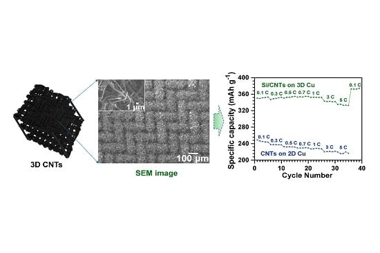
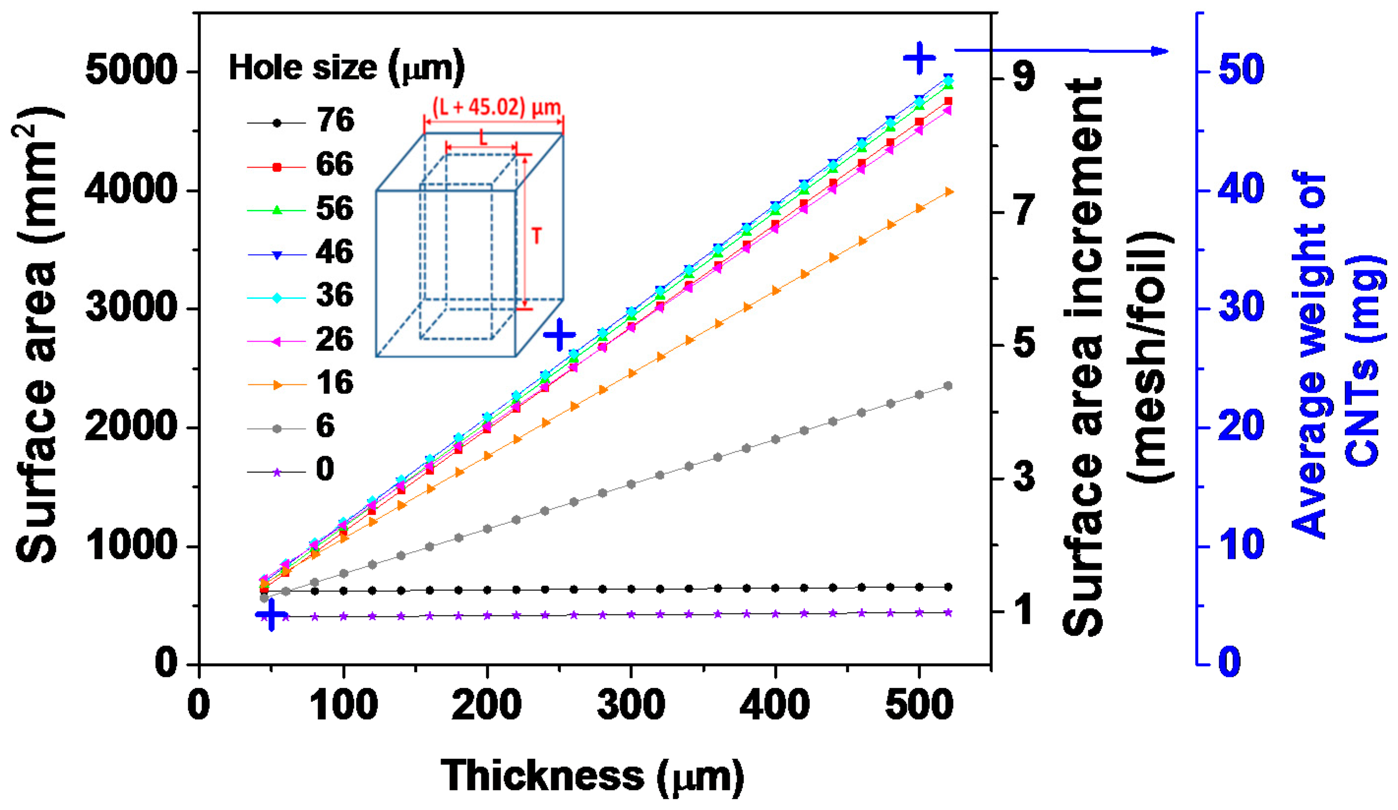
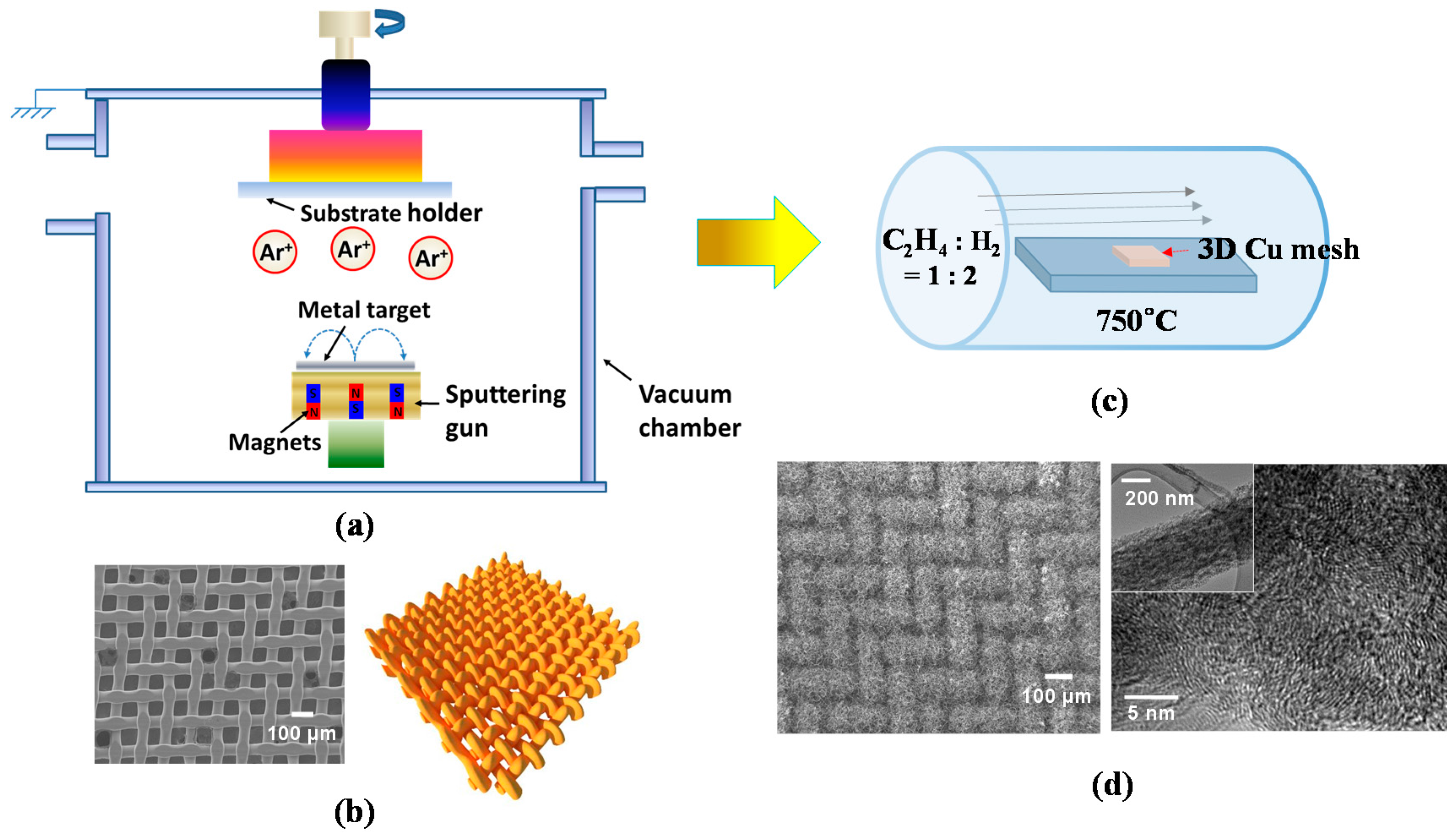
3.1. Fabrication of 3D CNTs
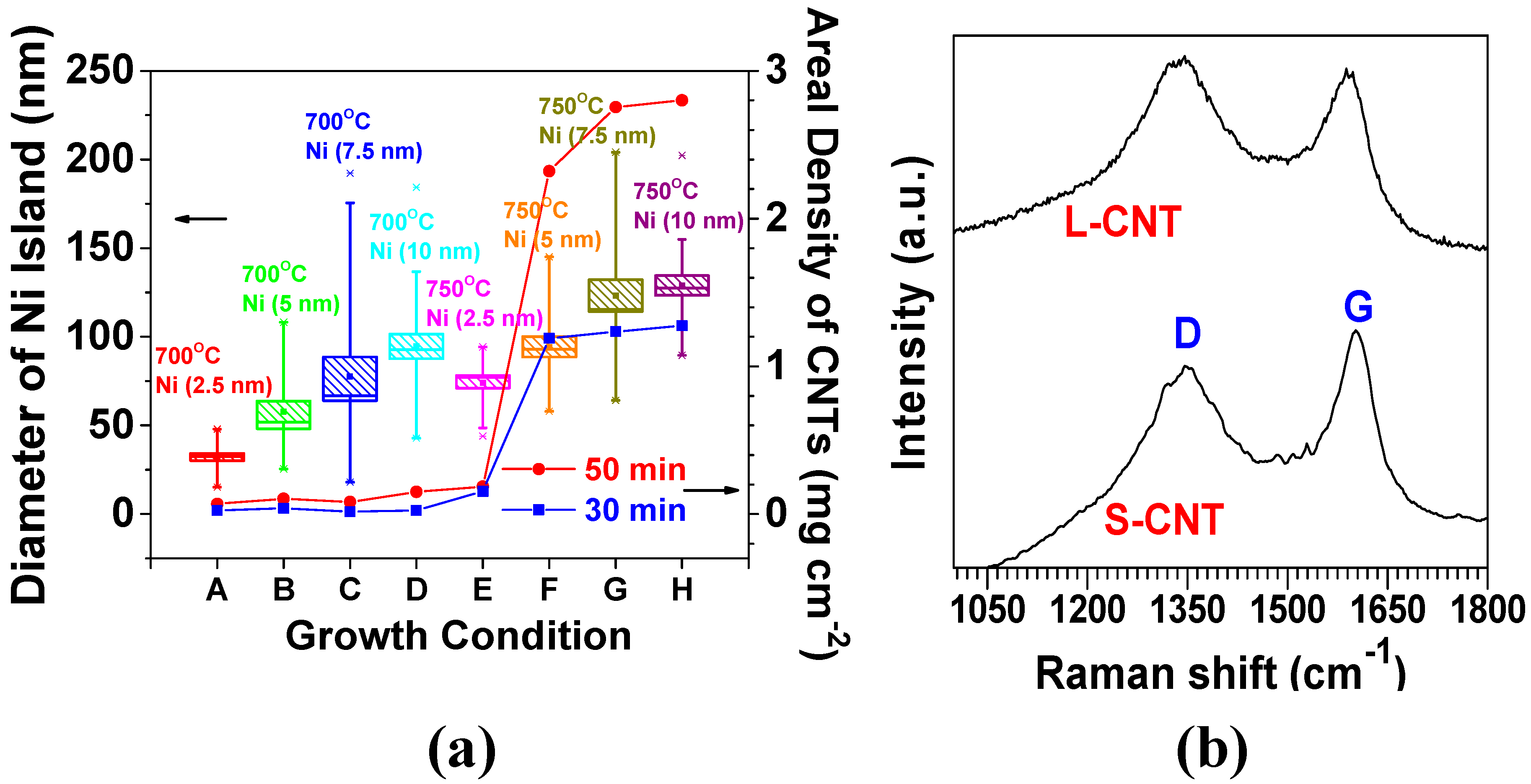
A 3D metal substrate as a current collector is beneficial for increasing the surface area of CNTs, consequently leading to a higher amount of Li+ ion intake into their structure, relative to its 2D counterpart [33]. Accordingly, we expect to attain superior electrochemical properties for advanced LIBs from 3D CNTs compared to the conventional 2D CNTs. Driven by this motivation, here we introduce a 3D interwoven Cu mesh as a substrate for the direct growth of CNTs. In this study, CNTs were grown on 3D Cu by a two-step method including sputtering for the deposition of catalytic thin layer (Ni and Ti) and thermal CVD. Figure 2a demonstrates the simple layout of magnetron sputtering system, where the main chamber is evacuated at a high vacuum of ~1 × 10⁻⁷ Torr, with a sputtering gun and substrate holder serving as cathode and anode, respectively.
For CNT growth, Ni was chosen as a catalytic metal and Ti as a diffusion barrier to prevent the formation of a Cu–Ni solid solution. The sputtering process involved plasma generation by Ar gas (~10 standard cubic centimeters per minute (SCCM)) at a power of ~75 W under a processing pressure of ~5 mTorr to deposit the uniform thin films of Ti and Ni on Cu mesh. After deposition of the thin films, Cu mesh/Ti (~10 nm)/Ni (~2.5–10 nm) layers were obtained. The Ti/Ni thin films were presumably nucleated and grown in an island (or Volmer–Weber) growth mode since the species (in our case, Ni atoms) are more strongly bonded to each other than to the substrate. Subsequently, these species lead to the coalescence of islands, thus forming a continuous film [89]. Figure 2b (left and right) represents a plane-view scanning electron microscopy (SEM) image of a 3D Cu mesh compressed at a pressure of 5000 bar along with the schematic of interwoven Cu wires of the mesh (200 Mesh Copper, TWP, Inc., Berkeley, CA, USA). Furthermore, CNTs have been grown by the chemical vapor deposition (CVD) technique, which has also been extensively employed to synthesize carbon nanomaterials such as carbon fibers, filaments, and nanotube materials for the past two to three decades [90]. Figure 2c shows a schematic diagram of a CVD reactor for CNT growth. The proposed model as depicted by Baker et al. explains the nucleation and growth mechanism of 3D CNTs on Cu in the following steps [91]: (1) a Ni thin layer could begin agglomerating as separate, spherical cap-shaped Ni islands (with an average size of 129 nm in Figure 1b (bottom)) due to thermal diffusion of Ni atoms at ~700 °C; (2) a carbon precursor gas (in our case, ethylene (C2H4)) is introduced into the CVD chamber, decomposed into carbon atoms, and diffused into the Ni islands from their surface to the core due to the thermal gradient in the Ni islands; (3) the carbon dissolves into the Ni islands until its optimum solubility limit and then precipitates below the end of Ni islands, promoting the growth of CNTs in the desired time frame. Figure 2d (left) shows the field emission scanning electron microscopy (FESEM) image of the as-grown 3D CNTs on Cu, highlighting densely packed and randomly oriented CNTs. The CNTs also show a low-ordered graphitization structure, revealed by a high-resolution transmission electron microscopy (HRTEM) (In Figure 2d (right), the inset shows a single CNT with an average diameter of 250 nm).

3.2. 3D CNT Growth

The morphology (e.g., length and diameter) of high-quality CNTs would be largely responsible for enhanced electrochemical properties of novel 3D CNT-based anodes comprising pure CNTs or hybrid nanomaterials (e.g., nanoscale silicon–CNTs and graphene–CNTs) for advanced LIBs [5]. To optimize the morphology of the CNTs, our team investigated the morphological variation of CNTs with growth condition (temperature and time) and the thickness of Ni catalysts (Table 2).
The rate of decomposition and diffusion of carbon into Ni atoms increased with an elevation in temperature, thus leading to the higher growth rate of CNTs [89,92]. In Figure 3a, the average agglomerated sizes (mean values) of Ni islands also increased from 32 to 74 nm (231%) with elevated temperature from 700 to 750 °C at 2.5 nm in the Ni thickness, and a similar trend is followed for the other cases of 5, 7.5, and 10 nm; this is largely attributed to the increased thermal diffusion of Ni atoms at an elevated temperature. The resulting large surface area of the Ni islands offers more sites for carbon adsorption, manifesting proper diffusion channels due to the large concentration gradient of carbon across the surface [89,92]. Empirically, an average diameter of CNTs (less than 100 nm) resulted from conditions with a growth temperature of 700 °C, a growth time of 50 min, and 10 nm thick Ni thin layer, whereas an average diameter of CNTs (200–300 nm) was obtained with an increased temperature of 750 °C at conditions with the same growth time and Ni thickness. Noticeably, a considerable increase in the average CNT diameter from 50 to 250 nm was obtained by increasing the Ni thickness from 2.5 to 5 nm at 750 °C. The areal density of CNTs was correspondingly augmented from less than 0.2 mg·cm−2 to greater than 2.2 mg·cm−2 for the growth time of 50 min. Furthermore, the areal density was increased from 1.3 mg·cm−2 to 2.8 mg·cm−2 (by 215%) when the growth time increased from 30 to 50 min under the conditions of 750 °C and 10 nm thick Ni. The degree of CNT crystallinity was investigated by considering two different diameters of 50 and 250 nm by using Raman spectroscopy analysis. The two samples were designated by S-CNT (the smaller diameter CNTs were grown by 2.5 nm thick Ni at a growth temperature of 750 °C) and L-CNT (the larger diameter CNTs were grown by 10 nm thick Ni at 750 °C), respectively (the morphologies of both S-CNT and L-CNT are shown in Table 2). Both S-CNT and L-CNT exhibited a similar peak ratio (ID/IG) (nearly 0.9) of D-band (~1350 cm−1) to G-band (~1580 cm−1), serving as fingerprints of disorder and sp2 graphene arrangement in the CNTs, respectively (Figure 3b). This result clarified that CNTs with a low degree of crystallinity can be grown at lower temperatures (700–750 °C in our study), relative to the graphitization temperature (2600–3300 °C). The low-degree crystalline CNTs are beneficial for facilitating the insertion and extraction of Li+ ions into and from the CNTs through the defects and the preferentially oriented graphene layers on the CNT surfaces [93,94]

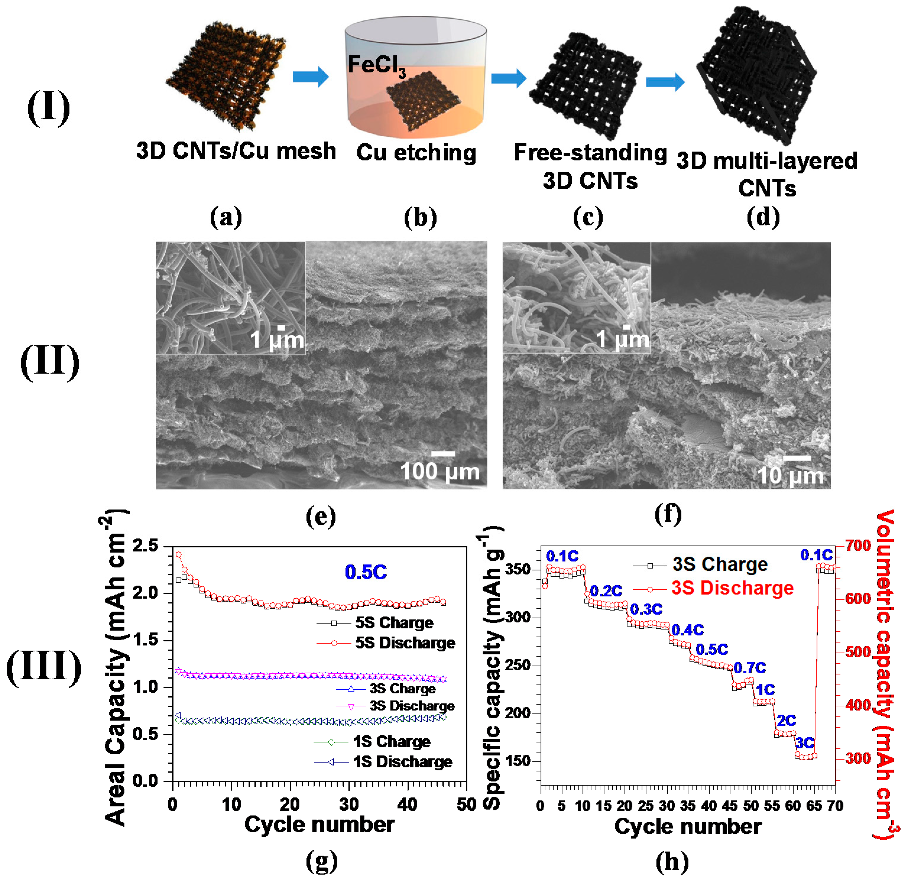
3.3. 3D Multi-Layered CNTs

Most of the nanocarbon-based anode materials have suffered from low mass loading and bulk density, which could hamper their practical applications in large-scale energy storage systems demanding high areal and volumetric capacity [29]. One legitimate strategy to overcome these hurdles is to design a multi-layered 3D CNT structure that efficiently increases its areal and bulk density. A multi-layered 3D CNT-based anode structure was fabricated by following the procedures outlined in Figure 4a–d. Bulk density of the compressed CNT layers was needed to obtain their volumetric capacity, determined by their thickness and footprint areas measured by a digital caliper (VWR). For comparison, untreated control multi-layered CNTs were also assembled at room temperature using a precision press (MTI Inc., Salt Lake City, UT, USA) with a minor pressure of 6 bar and without using the binder.
Figure 4e exhibits the multi-layered 3D CNTs with a low pressure of 6 bar. The overall thickness measured for this structure was ~780 μm, delivering areal and bulk densities of 34.9 mg·cm−2 and 0.45 g·cm−3, respectively. Such an exceptional areal density was nearly threefold higher than commercially available graphite anodes [95]. As expected, the miniscule applied pressure had no impact on the structural damage of the CNTs (inset of Figure 4e). To further increase the CNTs’ density, polyvinylidene fluoride (PVDF) is employed as a binder, followed by a hot press (detailed procedures were mentioned above). The compressed multi-layered CNTs reduced their overall thickness down to ~50 μm, augmenting the bulk density up to 1.8 g·cm−3 (Figure 4f). The denser CNT structure obtained by the hot press is seen in the close-up SEM image (inset of Figure 4f). The bulk densities for the three different multi-layered CNTs denoted by 1S (one layer), 3S (three layers), and 5S (five layers) were recorded to be 1.3, 1.85, and 1.8 g·cm−3, respectively.
Figure 4g shows the areal capacity behavior as a function of cycle number, highlighting the linear increase in areal capacity with the layer number of CNTs. As expected, 5S yields an average areal capacity of 1.92 mAh·cm−2, sufficient for commercial requirements, which is 173% and 275% superior to 3S and 1S, respectively [96]. Such a proportional increment of areal capacity suggests that assembling multi-layered CNTs will be a legitimate tactic for increasing the loading content of carbon nanomaterials and improving relevant areal capacity. Augmenting bulk density, obtained by compressing multi-layered CNTs, will lead to their enhanced volumetric capacity, a key parameter for the utilization of carbon nanomaterials in scaling up next-generation LIBs. The specific and volumetric capacities decreased stepwise with an increase in C-rate from 0.1C to 3C, which is mainly due to lowering the ionic conductivity of electrolytes with elevated C-rates [97]. The reversible capacities are recorded as 312 mAh·g−1 (578 mAh·cm−3), 251 mAh·g−1 (465 mAh·cm−3), 211 mAh·g−1 (390 mAh·cm−3), and 155 mAh·g−1 (287 mAh·cm−3) at 0.2C, 0.5C, 1C, and 3C, respectively. Furthermore, the capacity at 0.1C was rehabilitated to the initial value at the same C-rate after undergoing a C-rate test up to 3C, presumably highlighting the well-preserved structural integrity of 3S. The volumetric capacities of multi-layered 3D CNT anodes exceeded the recently published CNTs (48 mAh·cm−3 [98] and 395 mAh·cm−3 [99]), porous graphite (463 mAh·cm−3) [100] and commercial-grade graphitized mesocarbons (301.5 mAh·cm−3) [32]. With such excellent electrochemical properties, our proposed multi-layered CNT-based anodes can be envisioned to pave the way for the implementation of carbon nanomaterials to advanced LIBs demanding high volumetric capacity.

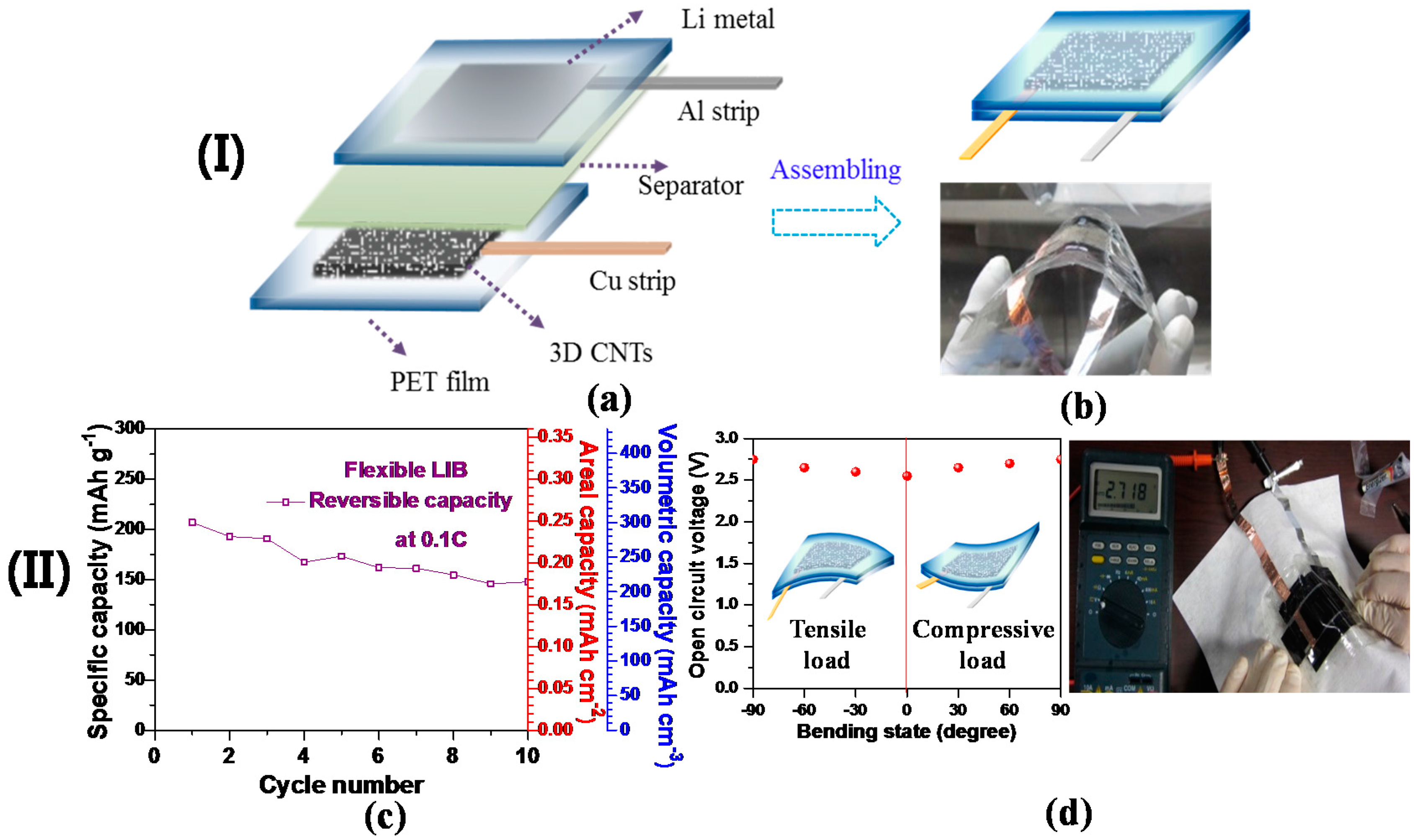
3.4. 3D CNT-Based Flexible LIB

Recent developments into flexible electronic devices have pioneered the key technologies in large-scale advanced flexible LIBs as a main power source [101]. Inspired by this technological progress, we designed a 3D free-standing CNT anode incorporated into a flexible LIB cell without compromising the areal and volumetric capacities. Figure 5a,b shows the schematic diagrams and digital image of our proposed flexible LIB cell to highlight each of its components. The as-grown 3D CNTs were transferred onto a graphene/PET film, thus acting as a working electrode (refer to Section 3.7 for brief procedures of graphene growth on Cu; refer to [63,102] for the process behind the subsequent transfer of graphene onto a polyethylene terephthalate (PET) film), while lithium metal adhered to a PET film was used for the reference and counter electrodes. In this assembly, no metal (e.g., Cu and Al) foils were used as a current collector for either cathode or anode in the flexible cell; as a result, this would allow for conformal contact between electroactive materials and metals. An assembled flexible LIB cell is represented by a schematic diagram and digital image (Figure 5). The open circuit voltage (OCV) of the flexible battery was recorded by a digital multi-tester. The charge (delithiation) and discharge (lithiation) cycles of the assembled cell with the 3D CNT-based anode were performed by using a battery-testing unit at room temperature at a C-rate of 0.1C in the cut-off voltage ranging from 0.01 to 3.0 V. The bulk density of 3D CNTs in the assembled cell was determined by their overall thickness via a digital caliper (VWR), thus obtaining volumetric capacity. A 3D CNT-based flexible LIB cell was subjected to electrochemical characterization with its relatively low total weight of ~65 mg and electroactive area of approximately 1 cm × 1 cm, although there is difficulty in comparing this cell with others due to a lack of standardization. Figure 5c demonstrates an areal capacity of the cell (~0.25 mAh·cm−2) at 0.1C, exceeding other flexible LIBs incorporated with graphene-based materials [103,104]. Moreover, the cell delivered a high volumetric capacity of ~300 mAh·cm−3 at 0.1C, acquired from a bulk density (1.45 g·cm−3) and a specific capacity (207 mAh·g−1) of the 3D CNTs. The capacity fading exhibited in the cell during cycling (Figure 5c) could be due to insufficient packaging of the LIB cell; the commercial packaging process could be a possible remedy for this shortcoming. Furthermore, nearly steady OCV values (2.55 V (flat) ~2.75 V (90° bending)) were recorded under deformed conditions (Figure 5d).

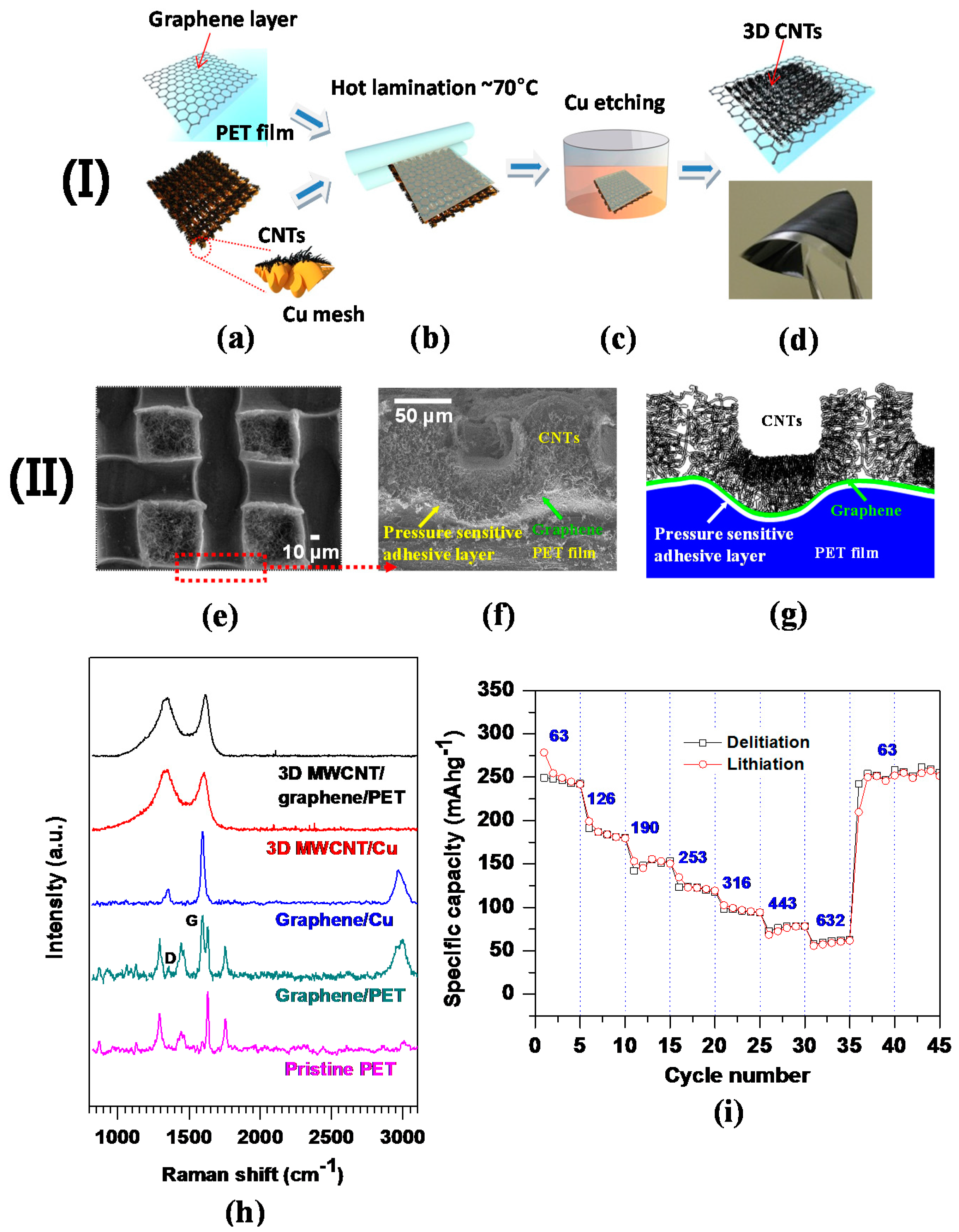
3.5. 3D Carbon Nanotube–Graphene Seamless Structure

Designing CNTs directly grown on metal has a high potential to be implemented in various device applications (e.g., supercapacitors); however, it has faced shortcomings of inadequate CNTs–metal interfacial contact and surface area utilization efficiency [105]. To overcome these shortcomings, we designed vertically aligned CNT forests directly grown on graphene fabricated on a 3D Ni substrate (hereafter, referred to as 3D CNTs–graphene–Ni) through a thermal CVD method via an Fe/Al2O3 catalyst layer. In this unique structure, the CNTs are strongly bonded to the graphene layer by covalent bonding, forming a seamless and robust CNTs–graphene hybrid architecture (Figure 6a), while graphene serves as an interfacial layer between the CNTs and the metal to realize the direct growth of high quality CNTs on 3D Ni. Figure 6b demonstrates SEM image of the as-obtained 3D CNTs-graphene-Ni, illustrating its well-interconnected network structure. The inset of Figure 6b gives a SEM image of the as-obtained structure; it also shows the length of CNTs in this structure, which was measured around 35 μm. The peak ratio (IG:ID) of G and D (appearing at 1580 cm−1 and 1350 cm−1, respectively) of the CNTs (~3:1) indicates a high degree of crystallinity of the CNTs from Raman spectra (Figure 6c). The presence of defects in CNTs is clarified by D peak and the defects largely stem from sp3 carbon atoms, derived during the growth process. The clear radial breathing mode (RBM) signals in the inset (left) of Figure 6c support different kinds of CNTs that are single-, double-, or triple-walled, with diameters ranging from 3 to 7 nm, as observed from the HRTEM images in the inset (right) of Figure 6c. The well-controlled contact interface of the 3D CNTs–graphene–Ni structure could be characterized by the capacitive properties of the structure (Figure 6d–f). In an electrochemical double-layer capacitor (EDLC) cell, the structure was used as an electrode, while aqueous KOH (6 M) was used as the electrolyte. Figure 6d shows the cyclic voltammograms (CVs) of the EDLC at various scan rates. The current response linearly increased as a function of scan rate, showing the typical (e.g., rectangular and symmetric) shape of the CV traces, associated with the good rate capability of the structure. Such a consistent shape of the CVs was seen at a high scan rate of 500 mV/s, highlighting low-contact resistance at the interface of the 3D CNTs–graphene–Ni structure [106,107,108]. The Nyquist plot shown in Figure 6e reveals the frequency response of the EDLC cell ranging from 1 MHz to 10 mHz. The line is almost parallel to the imaginary Z axis, indicating the ideal capacitive behavior. The resistance of electrolyte migration was determined to be 1.25 Ω from the semicircle traced by the enlarged data (the inset of Figure 6e) in the high-frequency region. The Galvanostatic charge–discharge traces in Figure 6f can be translated to specific capacitance values of 104, 99, 101, and 100 F·g−1 acquired at current densities of 0.2, 0.33, 0.67, and 1.00 A·g−1, respectively. The nearly consistent specific capacitances with the increasing scan rate until 1.00 A·g−1 point to the exceptional diffusion conductivity between the 3D CNTs–graphene structure and the electrolyte. These obtained values outperformed the EDLC assembled with CNTs directly grown on Inconel without graphene approximately fivefold and were also equivalent to the recently reported values of the EDLC assembled with graphene oxide [109,110,111]. Such an excellent electrochemical performance was largely due to the low-contact resistance at the interface of the 3D CNTs–graphene–Ni structure. This design is expected to show promising results when implemented into the application of Li-ion battery systems.

3.6. 3D Carbon Nanotube–Graphene for Flexible LIB

To date, carbon nanomaterial-based LIBs with flexible polymer substrates have faced drawbacks such as the low loading amount of electroactive materials and complicated fabrication processes [112]. Furthermore, higher specific and volumetric capacities of anodes featuring no metallic current collectors have been a hot topic for emerging flexible LIBs [101]. In light of these issues, a large-area patterned 3D CNTs–graphene hybrid anode structure was fabricated by a simple hot lamination process, transferring the CNTs grown on 3D Cu mesh onto graphene attached to a polyethylene terephthalate (PET) flexible film. In this structure, graphene served as a bridge to promote electrical conductivity throughout the 3D network of CNTs. Figure 7a–d represents the processing steps for the 3D CNTs on graphene–PET film. Good flexibility of the 3D CNTs–graphene–PET film was obtained; the physical flexibility inflicted no damage on the structure (Figure 7d). The exceptional flexibility and structural integrity were presumably attributed to pressure-sensitive adhesives coated on the commercial PET film, tethering 3D CNTs–graphene firmly to PET.
The patterned 3D CNT structure was successfully transferred and uniformly arrayed over the graphene–PET film, as shown in a FESEM plane view (Figure 7e). The high electrical conductivity (low sheet resistance of 8 Ω/sq) was measured for the 3D CNTs. Once the CNTs were transferred over the PET film, the 3D CNT structure was turned upside down with respect to its original structure on 3D Cu. The FESEM image of the darker regions (compared to the brighter box regions) represents the bottom side of the 3D CNT architecture directly grown on the Cu mesh substrate. When pressed by a thermal laminator, the upper regions of 3D CNTs on Cu were filled into the free spaces (i.e., the brighter box regions in the FESEM image, corresponding to the holes in the Cu mesh), thus exhibiting randomly oriented CNTs (Figure 7e). Compared with a CNTs–polycarbonate (PC) film fabricated by a small-scale and costly laser-jet patterning technique, and rolled quartz cylinders [113], the 3D CNTs–graphene–PET film had the following unique features: (1) graphene layers were intermediated with both heterogeneous materials of CNTs and PET, therefore serving as an electrical conducting agent; (2) the 3D CNTs–graphene–PET film was synthesized using a simple lamination process of CNTs grown on 3D Cu mesh. The overall height of the 3D CNTs on a PET film is estimated to be 40 µm and 3D CNTs are firmly adhered to PET through the adhesives coated on the PET film (Figure 7f). A schematic diagram also highlights the conformal adhesive layer by the white line, along with designation of other components (Figure 7g). Both the presence and crystallinity of CNTs and graphene are revealed by Raman spectroscopy analysis from two main peaks, G mode at ~1580 cm−1 (the first-order scattering of the E2g phonon of sp2 C atoms) and D mode at ~1350 cm−1 (k-point photons of A1g symmetry) [114]. Typical G and D peaks ensure the presence of graphene and CNTs grown on Cu and transferred onto a PET film (Figure 7h). Furthermore, the low degree of crystallinity of CNTs is validated by the intensity ratio of D to G mode peaks (ID/IG~1), seemingly attributed to the lower growth temperature (750 °C) relative to the graphitization temperature (2600–3300 °C).
The electrochemical characteristics of 3D CNTs–graphene as a working electrode were tested by using a 2032 coin-type half-cell, assembled with Li metal as counter and reference electrodes, and crescent-shaped Cu foil on the CNTs as a current collector. Specific capacities varied from 254 mAh·g−1 to 59 mAh·g−1 at different C-rates from 0.17C to 1.7C in a staircase manner (Figure 7i), and then the specific capacity was recovered to an initial capacity of ~254 mAh·g−1 (at 0.17C) after being subjected to the higher C-rate up to 1.7C. The stable and reversible specific capacities are comparable to other values from free-standing CNT films [13,18,19]. These findings secure the excellent C-rate capability of the flexible LIB anode, largely ascribed to outstanding structural integrity and interfacial bonding strength of 3D CNTs–graphene on PET.

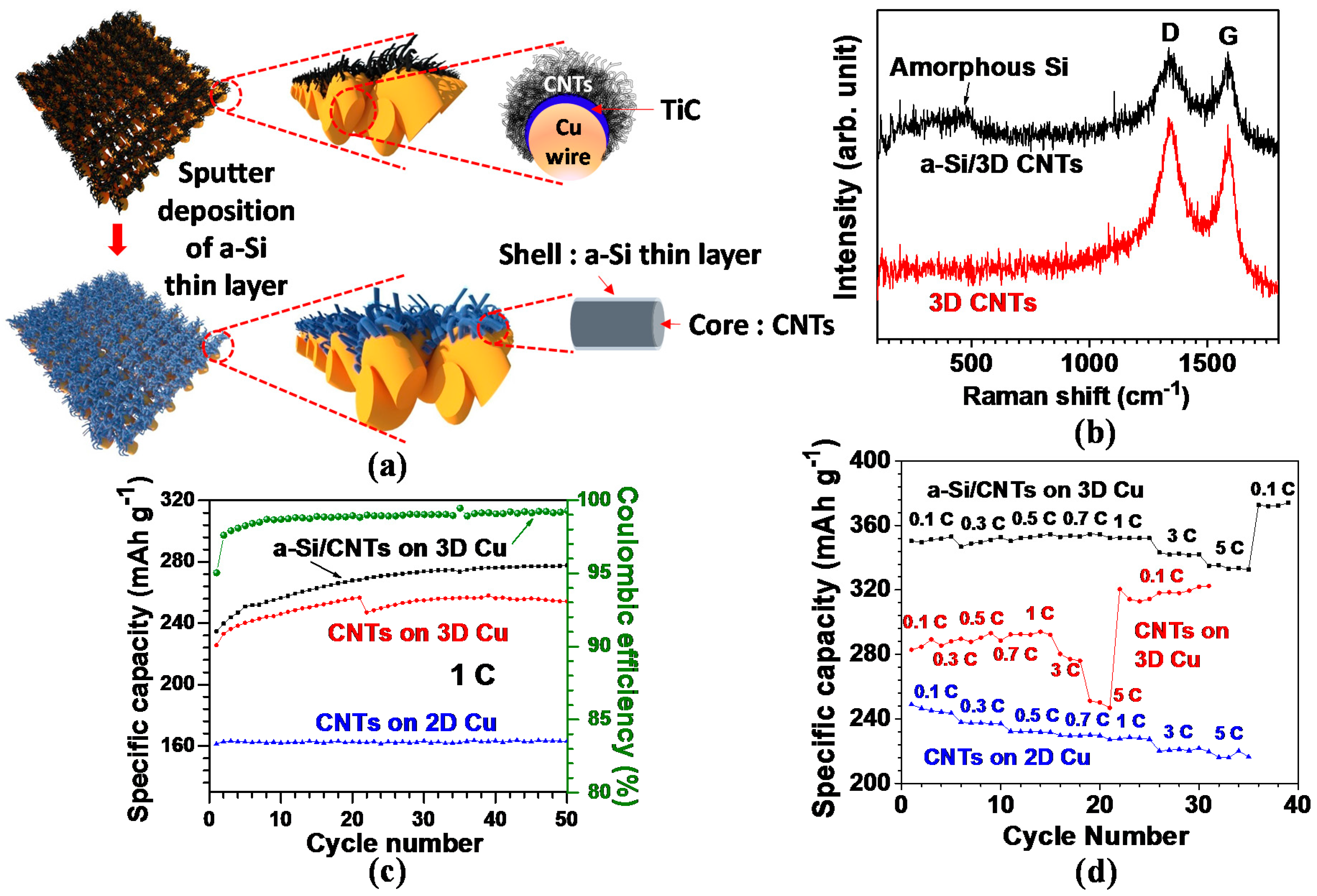
3.7. 3D Carbon Nanotube–Amorphous Silicon

Various types of hybrid anode nanostructures have been developed to induce a synergistic combination of two complementary nanomaterials for improved electrochemical performance. Recently, a 3D CNTs–silicon hybrid anode has gained great attention in obtaining the synergistic effects of 3D CNTs and silicon [45]. In this anode, 3D CNTs are used as an electrical conducting framework and structural buffer against ~300% volume variation of silicon during cycling; silicon, on the other hand, functions as a high-capacity material with a theoretical capacity of 4200 mAh·g−1. In our previous study, silicon was directly deposited onto the 3D CNTs via a sputtering method; as a result, it was possible to synthesize this anode without any complicated chemical processing steps [33]. Figure 8a illustrates the schematic of the cross-section view of CNTs grown on a single Cu wire, in which densely grown and larger diameter CNTs are demonstrated on the top surface area of Cu, with relatively smaller diameter CNTs on the lateral side area. In this proposed anode, the electrochemical performance was affected by the controlled interface between the CNTs as active material and Cu current collector [22,115]. Amorphous Si (a-Si) was subsequently coated on the as-grown 3D CNTs via the sputtering method and a Ti adhesion layer was intermediated with a-Si for reinforced bonding strength between a-Si and CNTs.
The high degree of defects can be seen in the high ratio of ID/IG (~1) for the CNTs in Raman spectra (Figure 8b). The larger extent of defects offers more accessible sites for Li+ ion insertion into the CNT structure and the decreased diffusion length for Li+ ions; as a result, the defective CNTs are more beneficial for enhancing electrochemical performance [93,94]. In the a-Si/CNTs hybrid structure, the broad intensity peak at roughly 480 cm−1 in Figure 8b verifies the existence of a-Si [116].
Figure 8c presents a comparative view of the cycling stabilities acquired from the three different anode systems for 50 cycles at 1C (corresponding to a current density of 372 mA g−1). For the 3D CNTs on Cu, the reversible capacity gradually rose from 226 mAh·g−1 at the 1st cycle to 258 mAh·g−1 at the 39th cycle, and then eventually dropped slightly to 254 mAh·g−1 up to the 50th cycle. Such a trend of increase in capacity over the entirety of the cycles is at odds with previous reports on the constant capacity of CNT [22,23]. This continuous charge and discharge process presumably activated more surface area on the close-packed and randomly oriented CNT structure. Compared with 3D CNTs, a-Si coated 3D CNTs yielded a capacity improved by nearly 10%, suggesting an alloy formation between a-Si and Li. Nevertheless, a specific capacity of 278 mAh·g−1 at the 50th cycle was lower than the previous reports on Si nanotubes [117] and Si nanowires [118], potentially due to the lower weight ratio of the deposited a-Si to CNTs (below 1%). The fairly stable cycling performance also ensured that Si–C bonding at the interface between a-Si and CNTs was robust without causing the a-Si layer to peel off when a-Si/3D CNT anode was cycled. Additionally, in the case of CNTs on 2D Cu foil (2D CNTs), a specific capacity of ~163 mAh·g−1 was delivered up to the 50th cycle. The capacity value was ~64% that of 3D CNTs, presumably attributed to a nearly 400% higher areal density of the 3D CNTs leading to greater Li+ ion accommodation abilities, as discussed in Section 1.
Coulombic efficiency (calculated by the ratio of charge (delithiation) capacity to discharge (lithiation) capacity) of a-Si/3D CNTs was recorded as higher than 98% after the 4th cycle and then nearly 99% after the 22nd cycle (Figure 8c). This finding verified the excellent reversibility of the a-Si/3D CNTs anode, attributed to the large amount of Li+ ions furnished by Li metal in a cell. Overall, the specific capacities of a-Si/3D CNTs are superior to 3D CNTs regardless of the C-rates (Figure 8d); an average capacity of the a-Si/3D CNTs (334 mAh·g−1 at 5C) outperformed 3D CNTs (249 mAh·g−1) by 34%. Moreover, the average capacity ratio of 5 and 0.1C for the a-Si/3D CNTs was measured around 0.93, exceeding 3D CNTs (0.86) by 8%. With the enhanced performance, we confirmed that a-Si thin layer incorporated with CNTs could be a promising approach toward the enhanced storage capacity for advanced LIBs. Furthermore, the overall capacities of 3D CNTs were higher than 2D CNTs over the entirety of the C-rates. The result could stem from the higher surface area contributed by a fourfold higher areal density of 3D CNTs for Li+ ion insertion abilities in conjunction with facilitated Li+ ion diffusion within the 3D structure.

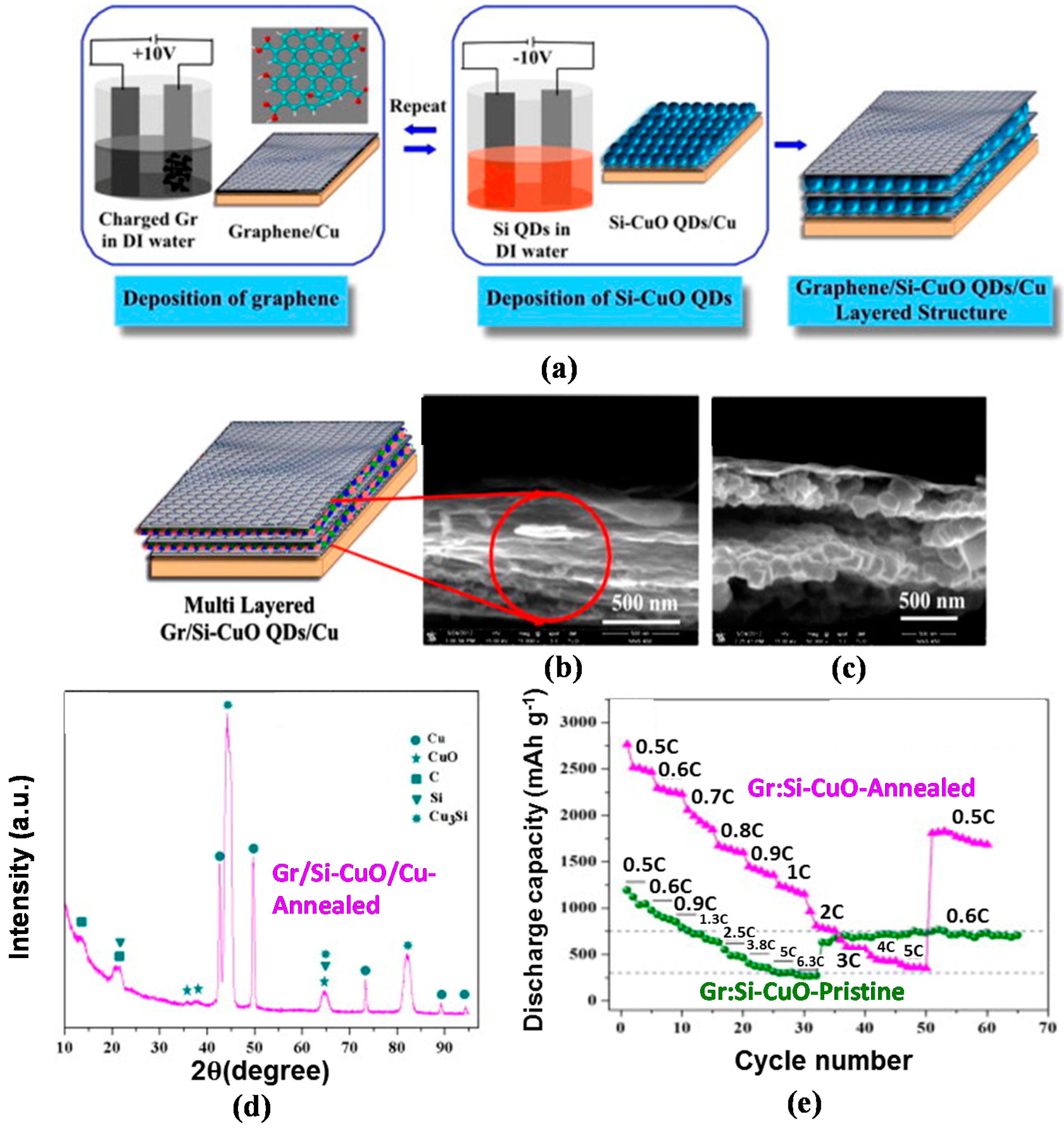
3.8. 3D Multi-Layered Structure of Graphene–Silicon Quantum Dots

The development of inter-layers in the 3D silicon–carbon nanostructure as a hybrid anode structure is a novel approach to enhancing the electrochemical properties of the LIBs. For this anode, the inter-layer serves as an electrical conducting and structural buffering agent and is more effective than recently developed silicon–nanocarbon hybrid anodes, which do not include an inter-layer; thus, this approach can resolve the issues of cycle-induced pulverization and low electrical conductivity of silicon [119,120]. Inspired by this concept, our research team formed an inter-layer Cu3Si as an electrical conducting and structural buffering media in the matrix of silicon–CuO quantum dots (hereafter referred to as Si–CuO QD) by thermal reduction in an Ar atmosphere [121,122,123]. Figure 9a represents processing flows of each synthesis step of Graphene/Silicon–CuO quantum dot (hereafter referred to as Gr/Si–CuO QD) multi-layered anode structure for LIB by using an electrophoresis deposition (EPD) technique. The graphene oxide (GO), a precursor to graphene, was fabricated through the modified Hummers method [124]. During fabrication, Cu was employed as anode to create the Si–CuO formation. Similar to the graphene growth on Cu (anodic deposition in Figure 9a (left)), Si–CuO thin film on Cu was carried out by repeating the cathodic deposition and followed by drying process until a desired thickness (15–100 nm) of Si–CuO thin layer was reached. A final product of Gr/Si–CuO layered thin films was obtained by alternating anodic and cathodic depositions, as depicted by the schematic diagram (Figure 9a (right)). For the fabrication of inter-layer Cu3Si in Si–CuO QD, subsequent reduction process was introduced by annealing at 400°C for 30 mins in Ar environment with a process pressure of 50 mTorr (as opposed to a base pressure of 10−7 mTorr) in a vacuum CVD system.
In this Gr/Si–CuO QD structure, the Si–CuO QD layer with a 15–100 nm thickness and wave-like graphene layer with a 5–10 nm thickness were stacked alternately (Figure 9b,c). The XRD pattern from the Gr/Si–CuO QD verifies the presence of components such as carbon and graphene oxide (PDF#46-0944), amorphous CuO (PDF#44-0706), poly-crystalline Cu3Si (PDF#51-0916), and Si, as denoted in Figure 9d. Figure 9e manifests the superior capacities of the Cu3Si-formed Gr/Si–CuO QD to the Gr/Si–CuO QD at the corresponding C-rates, along with a staircase-type capacity decrease as the C-rate increases. Furthermore, the Cu3Si-formed Gr/Si–CuO QD exhibited a 222% higher capacity of 2760 mAh·g−1 at 0.5C than the Gr/Si–CuO QD, and then the capacity gradually decreased to 350 mAh·g−1 at 5C with 12% capacity retention. Afterwards, once the C-rate returned to 0.5C, the capacity was elevated to 1810 mAh·g−1, which is 241% higher than the Gr/Si–CuO QD at a similar C-rate. The XRD, SEM, and Raman analyses corroborated the structural integrity of Gr/Si–CuO QD even after undergoing 100 discharge–charge cycles (see Supporting Information, Figure S1 [57]). Therefore, we confirmed the following dual functions of the inter-layer of Cu3Si for the outstanding C-rate capability and structural integrity of the Gr/Si–CuO QD structure: electrical conducting and structural cushioning media [125,126].

4. Conclusions and Perspectives

Efforts have been dedicated to develop 3D carbon nanostructured (e.g., CNTs, graphene, and nanoporous carbon) anodes in an attempt to implement them into advanced LIBs. The excellent electrochemical properties of these 3D carbon nanostructured anodes include high surface area, short diffusion length of Li+ ions, and high loading of active materials, which further contributes to higher LIB performance than conventional carbon nanostructured anodes. Furthermore, our proposed 3D CNTs and 3D graphene networks are being used in conjunction with high-capacity electroactive materials such as nanoscale metal-oxides/silicon to form the nano-heterostructure designs. By implementing such designs, the electrochemical performances have improved significantly over those pristine electroactive materials. However, most of the carbon nanostructures face the technical challenge of low Coulombic efficiency (the high irreversible capacity) obtained from the first cycle, mainly associated with the solid electrolyte interphase (SEI) layer formation by the organic electrolyte decomposition. The modification of either the surface of carbon nanomaterials or the electrolyte solution could be a viable way to solve this challenge in the future. Designing 3D nanocarbon conducting networks with high-capacity electrode materials for advanced LIBs can be applied to the emerging battery systems such as Li-sulfur, Li-air, and Li-organic batteries. This direction will bring forth many potential opportunities for the development of novel carbon nanostructures in the field of energy storage.

Acknowledgments

Wonbong Choi acknowledges partial support from Air Force Office of Scientific Research (AFOSR) (FA9550-11-1-0135 and FA9550-09-1-0544). Wonbong Choi and Mumukshu D. Patel also acknowledge partial support from the Advanced Materials and Manufacturing Processes Institute (AMMPI) at UNT.

Author Contributions

Wonbong Choi directed the experiments and wrote the paper; Chiwon Kang, Eunho Cha, and Mumukshu D. Patel performed the experiments and prepared the paper. H. Felix Wu provided additional comments for this paper. Chiwon Kang, Eunho Cha, and Mumukshu D. Patel contributed equally to the paper.

Conflicts of Interest

The authors declare no conflict of interest.

References

  1. Yang, Z.G.; Zhang, J.L.; Kintner-Meyer, M.C.W.; Lu, X.C.; Choi, D.W.; Lemmon, J.P.; Liu, J. Electrochemical energy storage for green grid. Chem. Rev. 2011, 111, 3577–3613. [Google Scholar] [CrossRef] [PubMed]
  2. Jeong, G.; Kim, Y.U.; Kim, H.; Kim, Y.J.; Sohn, H.J. Prospective materials and applications for Li secondary batteries. Energy Environ. Sci. 2011, 4, 1986–2002. [Google Scholar] [CrossRef]
  3. Winter, M.; Moeller, K.-C.; Besenhard, J.O. Carbonaceous and Graphitic Anodes. In Lithium Batteries: Science and Technology; Nazri, G.-A., Pistoia, G., Eds.; Springer: New York, NY, USA, 2004; pp. 144–194. [Google Scholar]
  4. Ji, L.; Lin, Z.; Alcoutlabi, M.; Zhang, X. Recent developments in nanostructured anode materials for rechargeable lithium-ion batteries. Energy Environ. Sci. 2011, 4, 2682–2699. [Google Scholar] [CrossRef]
  5. Landi, B.J.; Ganter, M.J.; Cress, C.D.; DiLeo, R.A.; Raffaelle, R.P. Carbon nanotubes for lithium ion batteries. Energy Environ. Sci. 2009, 2, 638–654. [Google Scholar] [CrossRef]
  6. Yoo, E.; Kim, J.; Hosono, E.; Zhou, H.; Kudo, T.; Honma, I. Large Reversible Li Storage of Graphene Nanosheet Families for Use in Rechargeable Lithium Ion Batteries. Nano Lett. 2008, 8, 2277–2282. [Google Scholar] [CrossRef] [PubMed]
  7. Ajayan, P.M.; Zhou, O.Z. Applications of Carbon Nanotubes. In Carbon Nanotubes Synthesis, Structure, Properties, and Application; Dresselhaus, M.S., Dresselhaus, G., Avouris, P., Eds.; Springer: New York, NY, USA, 2001; pp. 401–404. [Google Scholar]
  8. Aricò, A.S.; Bruce, P.; Scrosati, B.; Tarascon, J.M.; Schalkwijk, W.V. Nanostructured materials for advanced energy conversion and storage devices. Nat. Mater. 2005, 4, 366–377. [Google Scholar] [CrossRef] [PubMed]
  9. Che, G.; Lakshmi, B.B.; Fisher, E.R.; Martin, C.R. Carbon nanotubule membranes for electrochemical energy storage and production. Nature 1998, 393, 346–349. [Google Scholar] [CrossRef]
  10. Frackowiak, E.; Gautier, S.; Gaucher, H.; Bonnamy, S.; Beguin, F. Electrochemical storage of lithium in multiwalled carbon nanotubes. Carbon 1999, 37, 61–69. [Google Scholar] [CrossRef]
  11. Gao, B.; Bower, C.; Lorentzen, J.D.; Fleming, L.; Kleinhammes, A.; Tang, X.P.; McNeil, L.E.; Wu, Y.; Zhou, O. Enhanced saturation lithium composition in ball-milled single-walled carbon nanotubes. Chem. Phys. Lett. 2000, 327, 69–75. [Google Scholar] [CrossRef]
  12. Shin, H.C.; Liu, M.; Sadanadan, B.; Rao, A.M. Lithium insertion into chemically etched multi-walled carbon nanotubes. J. Solid State Electrochem. 2004, 8, 908–913. [Google Scholar] [CrossRef]
  13. Chen, J.; Minett, A.I.; Liu, Y.; Lynam, C.; Sherrell, P.; Wang, C.; Wallace, G.G. Direct Growth of Flexible Carbon Nanotube Electrodes. Adv. Mater. 2008, 20, 566–570. [Google Scholar] [CrossRef]
  14. Wang, X.X.; Wang, J.N.; Chang, H.; Zhang, Y.F. Preparation of Short Carbon Nanotubes and Application as an Electrode Material in Li-Ion Batteries. Adv. Funct. Mater. 2007, 17, 3613–3618. [Google Scholar] [CrossRef]
  15. Ng, S.H.; Wang, J.; Guo, Z.P.; Chen, J.; Wang, G.X.; Liu, H.K. Single wall carbon nanotube paper as anode for lithium-ion battery. Electrochim. Acta 2005, 51, 23–28. [Google Scholar] [CrossRef]
  16. Shah, A.; Ates, M.N.; Kotz, S.; Seo, J.; Abraham, M.; Somu, S.; Busnaina, A. A Layered Carbon Nanotube Architecture for High Power Lithium Ion Batteries. J. Electrochem. Soc. 2014, 161, A989–A995. [Google Scholar] [CrossRef]
  17. Yang, S.; Huo, J.; Song, H.; Chen, X. A comparative study of electrochemical properties of two kinds of carbon nanotubes as anode materials for lithium ion batteries. Electrochim. Acta 2008, 53, 2238–2244. [Google Scholar] [CrossRef]
  18. Chew, S.Y.; Ng, S.H.; Wang, J.; Novák, P.; Krumeich, F.; Chou, S.L.; Chen, J.; Liu, H.K. Flexible free-standing carbon nanotube films for model lithium-ion batteries. Carbon 2009, 47, 2976–2983. [Google Scholar] [CrossRef]
  19. Yoon, S.; Lee, S.; Kim, S.; Park, K.W.; Cho, D.; Jeong, Y. Carbon nanotube film anodes for flexible lithium ion batteries. J. Power Sources 2015, 279, 495–501. [Google Scholar] [CrossRef]
  20. Qie, L.; Chen, W.M.; Wang, Z.H.; Shao, Q.G.; Li, X.; Yuan, L.X.; Hu, X.L.; Zhang, W.X.; Huang, Y.H. Nitrogen-Doped Porous Carbon Nanofiber Webs as Anodes for Lithium Ion Batteries with a Superhigh Capacity and Rate Capability. Adv. Mater. 2012, 24, 2047–2050. [Google Scholar] [CrossRef] [PubMed]
  21. Li, X.; Yang, J.; Hu, Y.; Wang, J.; Li, Y.; Cai, M.; Li, R.; Sun, X. Novel approach toward a binder-free and current collector-free anode configuration: Highly flexible nanoporous carbon nanotube electrodes with strong mechanical strength harvesting improved lithium storage. J. Mater. Chem. 2012, 22, 18847–18853. [Google Scholar] [CrossRef]
  22. Lahiri, I.; Oh, S.W.; Hwang, J.Y.; Cho, S.; Sun, Y.K.; Banerjee, R.; Choi, W. High Capacity and Excellent Stability of Lithium Ion Battery Anode Using Interface-Controlled Binder-Free Multiwall Carbon Nanotubes Grown on Copper. ACS Nano 2010, 4, 3440–3446. [Google Scholar] [CrossRef] [PubMed]
  23. Lahiri, I.; Oh, S.M.; Hwang, J.Y.; Kang, C.W.; Choi, M.S.; Jeon, H.T.; Banerjee, R.; Sun, Y.K.; Choi, W.B. Ultrathin alumina-coated carbon nanotubes as an anode for high capacity Li-ion batteries. J. Mater. Chem. 2011, 21, 13621–13626. [Google Scholar] [CrossRef]
  24. Luo, B.; Zhi, L. Design and construction of three dimensional graphene-based composites for lithium ion battery applications. Energy Environ. Sci. 2015, 8, 456–477. [Google Scholar] [CrossRef]
  25. Raccichini, R.; Varzi, A.; Passerini, S.; Scrosati, B. The role of graphene for electrochemical energy storage. Nat. Mater. 2015, 14, 271–279. [Google Scholar] [CrossRef] [PubMed]
  26. Zhou, G.; Wang, D.W.; Yin, L.C.; Li, N.; Li, F.; Cheng, H.M. Oxygen Bridges between NiO Nanosheets and Graphene for Improvement of Lithium Storage. ACS Nano 2012, 6, 3214–3223. [Google Scholar] [CrossRef] [PubMed]
  27. Hou, J.; Cao, C.; Idrees, F.; Ma, X. Hierarchical Porous Nitrogen-Doped Carbon Nanosheets Derived from Silk for Ultrahigh-Capacity Battery Anodes and Supercapacitors. ACS Nano 2015, 9, 2556–2564. [Google Scholar] [CrossRef] [PubMed]
  28. Roberts, A.D.; Li, X.; Zhang, H. Porous carbon spheres and monoliths: Morphology control, pore size tuning and their applications as Li-ion battery anode materials. Chem. Soc. Rev. 2014, 43, 4341–4356. [Google Scholar] [CrossRef] [PubMed]
  29. Gogotsi, Y.; Simon, P. True Performance Metrics in Electrochemical Energy Storage. Science 2011, 334, 917–918. [Google Scholar] [CrossRef] [PubMed] [Green Version]
  30. Zhang, C.; Lv, W.; Tao, Y.; Yang, Q.H. Towards superior volumetric performance: Design and preparation of novel carbon materials for energy storage. Energy Environ. Sci. 2015, 8, 1390–1403. [Google Scholar] [CrossRef]
  31. Chen, Z.; Zhang, D.; Wang, X.; Jia, X.; Wei, F.; Li, H.; Lu, Y. High-Performance Energy-Storage Architectures from Carbon Nanotubes and Nanocrystal Building Blocks. Adv. Mater. 2012, 24, 2030–2036. [Google Scholar] [CrossRef] [PubMed]
  32. Novák, P.; Goers, D.; Spahr, M.E. Carbon Materials in Lithium-Ion Batteries. In Carbons for Electrochemical Energy Storage and Conversion Systems; Béguin, F., Frąckowiak, E., Eds.; CRC Press: Boca Raton, FL, USA, 2010; p. 300. [Google Scholar]
  33. Kang, C.W.; Lahiri, I.; Baskaran, R.; Kim, W.G.; Sun, Y.K.; Choi, W.B. 3-dimensional carbon nanotube for Li-ion battery anode. J. Power Sources 2012, 219, 364–370. [Google Scholar] [CrossRef]
  34. Dillon, S.J.; Sun, K. Microstructural design considerations for Li-ion battery systems. Curr. Opin. Solid State Mater. Sci. 2012, 16, 153–162. [Google Scholar] [CrossRef]
  35. Zhang, H.; Yu, X.; Braun, P.V. Three-dimensional bicontinuous ultrafast-charge and -discharge bulk battery electrodes. Nat. Nanotechnol. 2011, 6, 277–281. [Google Scholar] [CrossRef] [PubMed]
  36. Zhang, H.G.; Braun, P.V. Three-dimensional metal scaffold supported bicontinuous silicon battery anodes. Nano Lett. 2012, 12, 2778–2783. [Google Scholar] [CrossRef] [PubMed]
  37. Arbizzani, C.; Beninati, S.; Lazzari, M.; Mastragostino, M. Carbon paper as three-dimensional conducting substrate for tin anodes in lithium-ion batteries. J. Power Sources 2005, 141, 149–155. [Google Scholar] [CrossRef]
  38. Cheah, S.K.; Perre, E.; Rooth, M.; Fondell, M.; Hårsta, A.; Nyholm, L.; Boman, M.; Gustafsson, T.; Lu, J.; Simon, P.; et al. Self-Supported Three-Dimensional Nanoelectrodes for Microbattery Applications. Nano Lett. 2009, 9, 3230–3233. [Google Scholar] [CrossRef] [PubMed]
  39. Zhang, Y.Q.; Xia, X.H.; Wang, X.L.; Mai, Y.J.; Shi, S.J.; Tang, Y.Y.; Gu, C.G.; Tu, J.P. Three-dimensional porous nano-Ni supported silicon composite film for high-performance lithium-ion batteries. J. Power Sources 2012, 213, 106–111. [Google Scholar] [CrossRef]
  40. Taberna, L.; Mitra, S.; Poizot, P.; Simon, P.; Tarascon, J.M. High rate capabilities Fe3O4-based Cu nano-architectured electrodes for lithium-ion battery applications. Nat. Mater. 2006, 5, 567–573. [Google Scholar] [CrossRef] [PubMed]
  41. Kim, J.H.; Myung, S.T.; Sun, Y.K. Molten salt synthesis of LiNi0.5Mn1.5O4 spinel for 5 V class cathode material of Li-ion secondary battery. Electrochim. Acta 2004, 49, 219–227. [Google Scholar] [CrossRef]
  42. Guo, J.C.; Wang, C.S. A polymer scaffold binder structure for high capacity silicon anode of lithium-ion battery. Chem. Commun. 2010, 46, 1428–1430. [Google Scholar] [CrossRef] [PubMed]
  43. Gregorczyk, K.E.; Kozen, A.C.; Chen, X.; Schroeder, M.A.; Cao, M.N.A.; Hu, L.; Rubloff, G.W. Fabrication of 3D Core–Shell Multiwalled Carbon Nanotube@RuO2 Lithium-Ion Battery Electrodes through a RuO2 Atomic Layer Deposition Process. ACS Nano 2015, 9, 464–473. [Google Scholar] [CrossRef] [PubMed]
  44. Lahiri, I.; Choi, W. Carbon Nanostructures in Lithium Ion Batteries: Past, Present, and Future. Crit. Rev. Solid State Mater. Sci. 2013, 38, 128–166. [Google Scholar] [CrossRef]
  45. De Las Casas, C.; Li, W. A review of application of carbon nanotubes for lithium ion battery anode material. J. Power Sources 2012, 208, 74–85. [Google Scholar] [CrossRef]
  46. Kaskhedikar, N.A.; Maier, J. Lithium Storage in Carbon Nanostructures. Adv. Mater. 2009, 21, 2664–2680. [Google Scholar] [CrossRef]
  47. Yang, Z.; Ren, J.; Zhang, Z.; Chen, X.; Guan, G.; Qiu, L.; Zhang, Y.; Peng, H. Recent Advancement of Nanostructured Carbon for Energy. Chem. Rev. 2015, 115, 5159–5223. [Google Scholar] [CrossRef] [PubMed]
  48. Lee, T.I.; Jegal, J.P.; Park, J.H.; Choi, W.H.; Lee, J.O.; Kim, K.B.; Myoung, J.M. Three-Dimensional Layer-by-Layer Anode Structure Based on Co3O4 Nanoplates Strongly Tied by Capillary-like Multiwall Carbon Nanotubes for Use in High-Performance Lithium-Ion Batteries. ACS Appl. Mater. Interfaces 2015, 7, 3861–3865. [Google Scholar] [CrossRef] [PubMed]
  49. Kang, C.W.; Cha, E.; Baskaran, R.; Choi, W.B. Three-dimensional free-standing carbon nanotubes (CNTs) for flexible lithium-ion battery anode. Nanotechnology 2016, 27, 105402. [Google Scholar] [CrossRef] [PubMed]
  50. Chen, X.; Zhu, H.; Chen, Y.C.; Shang, Y.; Cao, A.; Hu, L.; Rubloff, G.W. MWCNT/V2O5 Core/Shell Sponge for High Areal Capacity and Power Density Li-Ion Cathodes. ACS Nano 2012, 6, 7948–7955. [Google Scholar] [CrossRef] [PubMed]
  51. Hu, L.; Wu, H.; Gao, Y.; Cao, A.; Li, H.; McDough, J.; Xie, X.; Zhou, M.; Cui, Y. Silicon–Carbon Nanotube Coaxial Sponge as Li-Ion Anodes with High Areal Capacity. Adv. Energy Mater. 2011, 1, 523–527. [Google Scholar] [CrossRef]
  52. Hu, L.; Mantia, F.L.; Wu, H.; Xie, X.; McDonough, J.; Pasta, M.; Cui, Y. Lithium-Ion Textile Batteries with Large Areal Mass Loading. Adv. Energy Mater. 2011, 1, 1012–1017. [Google Scholar] [CrossRef]
  53. Xiao, Q.; Fan, Y.; Wang, X.; Susantyoko, R.A.; Zhang, Q. A multilayer Si/CNT coaxial nanofiber LIB anode with a high areal capacity. Energy Environ. Sci. 2014, 7, 655–661. [Google Scholar] [CrossRef]
  54. Li, Y.; Zhang, H.; Shen, P.K. Ultrasmall metal oxide nanoparticles anchored on three-dimensional hierarchical porous gaphene-like networks as anode for high-performance lithium ion batteries. Nano Energy 2015, 13, 563–572. [Google Scholar] [CrossRef]
  55. Yang, Y.; Fan, X.; Casillas, G.; Peng, Z.; Ruan, G.; Wang, G.; Yacaman, M.J.; Tour, J.M. Three-Dimensional Nanoporous Fe2O3/Fe3C-Graphene Heterogeneous Thin Films for Lithium-Ion Batteries. ACS Nano 2014, 8, 3939–3946. [Google Scholar] [CrossRef] [PubMed]
  56. Xin, X.; Zhou, X.; Wang, F.; Yao, X.; Xu, X.; Zhu, Y.; Liu, Z. A 3D porous architecture of Si/graphene nanocomposite as high-performance anode materials for Li-ion batteries. J. Mater. Chem. 2012, 22, 7724–7730. [Google Scholar] [CrossRef]
  57. Rangasamy, B.; Hwang, J.Y.; Choi, W.B. Multi layered Si–CuO quantum dots wrapped by graphene for high-performance anode material in lithium-ion battery. Carbon 2014, 77, 1065–1072. [Google Scholar] [CrossRef]
  58. Shen, L.; Zhang, X.; Li, H.; Yuan, C.; Cao, G. Design and Tailoring of a Three-Dimensional TiO2-Graphene-Carbon Nanotube Nanocomposite for Fast Lithium Storage. J. Phys. Chem. Lett. 2011, 2, 3096–3101. [Google Scholar] [CrossRef]
  59. Li, N.; Chen, Z.; Ren, W.; Li, F.; Cheng, H.M. Flexible graphene-based lithium ion batteries with ultrafast charge and discharge rates. Proc. Natl. Acad. Sci. USA 2012, 109, 17360–17365. [Google Scholar] [CrossRef] [PubMed]
  60. Tao, L.; Zai, J.; Wang, K.; Wan, Y.; Zhang, H.; Yu, C.; Xiao, Y.; Qian, X. 3D-hierarchical NiO–graphene nanosheet composites as anodes for lithium ion batteries with improved reversible capacity and cycle stability. RSC Adv. 2012, 2, 3410–3415. [Google Scholar] [CrossRef]
  61. Wang, B.; Li, X.; Qiu, T.; Luo, B.; Ning, J.; Li, J.; Zhang, X.; Liang, M.; Zhi, L. High Volumetric Capacity Silicon-Based Lithium Battery Anodes by Nanoscale System Engineering. Nano Lett. 2013, 13, 5578–5584. [Google Scholar] [CrossRef] [PubMed]
  62. Qin, J.; He, C.; Zhao, N.; Wang, Z.; Shi, C.; Liu, E.N.; Li, J. Graphene Networks Anchored with Sn@Graphene as Lithium Ion Battery Anode. ACS Nano 2014, 8, 1728–1738. [Google Scholar] [CrossRef] [PubMed]
  63. Kang, C.W.; Baskaran, R.; Hwang, J.Y.; Ku, B.C.; Choi, W.B. Large Scale Patternable 3-Dimensional Carbon Nanotubes-Graphene Structure for Flexible Li-ion Battery. Carbon 2014, 68, 493–500. [Google Scholar] [CrossRef]
  64. Li, L.; Zhou, G.; Weng, Z.; Shan, X.Y.; Li, F.; Cheng, H.M. Monolithic Fe2O3/graphene hybrid for highly efficient lithium storage and arsenic removal. Carbon 2014, 67, 500–507. [Google Scholar] [CrossRef]
  65. Wang, R.; Xu, C.; Sun, J.; Gao, L.; Lin, C. Flexible free-standing hollow Fe3O4/graphene hybrid films for lithium-ion batteries. J. Mater. Chem. A 2013, 1, 1794–1800. [Google Scholar] [CrossRef]
  66. Yu, A.; Park, H.W.; Davies, A.; Higgins, D.C.; Chen, Z.; Xiao, X. Free-Standing Layer-By-Layer Hybrid Thin Film of Graphene-MnO2 Nanotube as Anode for Lithium Ion Batteries. J. Phys. Chem. Lett. 2011, 2, 1855–1860. [Google Scholar] [CrossRef]
  67. Wang, G.; Wang, B.; Wang, X.; Park, J.; Dou, S.; Ahn, H.; Kim, K. Sn/graphene nanocomposite with 3D architecture for enhanced reversible lithium storage in lithium ion batteries. J. Mater. Chem. 2009, 19, 8378–8384. [Google Scholar] [CrossRef]
  68. Zhou, H.; Zhu, S.; Hibino, M.; Honma, I.; Ichihara, M. Lithium Storage in Ordered Mesoporous Carbon (CMK-3) with High Reversible Specific Energy Capacity and Good Cycling Performance. Adv. Mater. 2003, 15, 2107–2111. [Google Scholar] [CrossRef]
  69. Hu, Y.S.; Adelhelm, P.; Smarsly, B.M.; Hore, S.; Antonietti, M.; Maier, J. Synthesis of Hierarchically Porous Carbon Monoliths with Highly Ordered Microstructure and Their Application in Rechargeable Lithium Batteries with High-Rate Capability. Adv. Funct. Mater. 2007, 17, 1873–1878. [Google Scholar] [CrossRef]
  70. Fang, B.; Kim, M.S.; Kim, J.H.; Lim, S.; Yu, J.S. Ordered multimodal porous carbon with hierarchical nanostructure for high Li storage capacity and good cycling performance. J. Mater. Chem. 2010, 20, 10253–10259. [Google Scholar] [CrossRef]
  71. Xu, Y.; Guo, J.; Wang, C. Sponge-like porous carbon/tin composite anode materials for lithium ion batteries. J. Mater. Chem. 2012, 22, 9562–9567. [Google Scholar] [CrossRef]
  72. Bresser, D.; Paillard, E.; Passerini, S. Lithium-ion batteries (LIBs) for medium- and large-scale energy storage. In Advances in Batteries for Medium and Large-Scale Energy Storage; Menictas, C., Skyllas-Kazacos, M., Mariana, L.T., Eds.; Elsevier: Waltham, MA, USA, 2015; pp. 125–211. [Google Scholar]
  73. Peled, E.; Menachem, C.; Bar-Tow, D.; Melman, A. Improved Graphite Anode for Lithium-Ion Batteries Chemically Bonded Solid Electrolyte Interface and Nanochannel Formation. J. Electrochem. Soc. 1996, 143, L4–L7. [Google Scholar] [CrossRef]
  74. Placke, T.; Siozios, V.; Schmitz, R.; Lux, S.F.; Bieker, P.; Colle, C.; Meyer, H.; Passerini, S.; Winter, M. Influence of graphite surface modifications on the ratio of basal plane to “non-basal plane” surface area and on the anode performance in lithium ion batteries. J. Power Sources 2012, 200, 83–91. [Google Scholar] [CrossRef]
  75. Yu, P.; Ritter, J.; White, R.; Popov, B. Ni-composite microencapsulated graphite as the negative electrode in lithium-ion batteries - I. Initial irreversible capacity study. J. Electrochem. Soc. 2000, 147, 1280–1285. [Google Scholar] [CrossRef]
  76. Yu, P.; Ritter, J.; White, R.; Popov, B. Ni-composite microencapsulated graphite as the negative electrode in lithium-ion batteries II. Electrochemical impedance and self-discharge studies. J. Electrochem. Soc. 2000, 147, 2081–2085. [Google Scholar] [CrossRef]
  77. Doi, T.; Fukutsuka, T.; Takeda, K.; Abe, T.; Miyazaki, K.; Ogumi, Z. Surface Modification of Graphitized Carbonaceous Thin-Film Electrodes with Silver for Enhancement of Interfacial Lithium-Ion Transfer. J. Phys. Chem. C 2012, 116, 12422–12425. [Google Scholar] [CrossRef]
  78. Doi, T.; Takeda, K.; Fukutsuka, T.; Iriyama, Y.; Abe, T.; Ogumi, Z. Surface modification of graphitized carbonaceous materials by electropolymerization of thiophene and their effects on electrochemical properties. Carbon 2005, 43, 2352–2357. [Google Scholar] [CrossRef]
  79. Gaberscek, M.; Bele, M.; Drofenik, J.; Dominko, R.; Pejovnik, S. Improved carbon anode properties: Pretreatment of particles in polyelectrolyte solution. J. Power Sources 2001, 97–98, 67–69. [Google Scholar] [CrossRef]
  80. Gaberscek, M.; Bele, M.; Drofenik, J.; Dominko, R.; Pejovnik, S. Improved carbon anode for lithium batteries - Pretreatment of carbon particles in a polyelectrolyte solution. Electrochem. Solid State Lett. 2000, 3, 171–173. [Google Scholar] [CrossRef]
  81. Pan, Q.; Wang, H.; Jiang, Y. Natural graphite modified with nitrophenyl multilayers as anode materials for lithium ion batteries. J. Mater. Chem. 2007, 17, 329–334. [Google Scholar] [CrossRef]
  82. Yoshio, M.; Wang, H.; Fukuda, K.; Umeno, T.; Abe, T.; Ogumi, Z. Improvement of natural graphite as a lithium-ion battery anode material, from raw flake to carbon-coated sphere. J. Mater. Chem. 2004, 14, 1754–1758. [Google Scholar] [CrossRef]
  83. Yoon, S.; Kim, H.; Oh, S.M. Surface modification of graphite by coke coating for reduction of initial irreversible capacity in lithium secondary batteries. J. Power Sources 2001, 94, 68–73. [Google Scholar] [CrossRef]
  84. Kim, J.-S.; Yoon, W.-Y.; Yoo, K.S.; Park, G.-S.; Lee, C.W.; Murakami, Y.; Shindo, D. Charge–discharge properties of surface-modified carbon by resin coating in Li-ion battery. J. Power Sources 2002, 104, 175–180. [Google Scholar] [CrossRef]
  85. Ren, Y.; Wang, J.; Huang, X.; Ding, J. The synthesis of polypyrrole@Mn3O4/reduced graphene oxide anode with improved coulombic efficiency. Electrochim. Acta 2015, 186, 345–352. [Google Scholar] [CrossRef]
  86. Fu, K.; Xue, L.; Yildiz, O.; Li, S.; Lee, H.; Li, Y.; Xu, G.; Zhou, L.; Bradford, P.D.; Zhang, X. Effect of CVD carbon coatings on Si@CNF composite as anode for lithium-ion batteries. Nano Energy 2013, 2, 976–986. [Google Scholar] [CrossRef]
  87. Wang, Q.; Li, H.; Chen, L.; Huang, X. Novel spherical microporous carbon as anode material for Li-ion batteries. Solid State Ion. 2002, 152, 43–50. [Google Scholar] [CrossRef]
  88. Kang, C.W.; Patel, M.; Baskaran, R.; Jung, K.N.; Xia, C.; Shi, S.; Choi, W.B. Three-dimensional carbon nanotubes for high capacity lithium-ion batteries. J. Power Sources 2015, 299, 465–471. [Google Scholar] [CrossRef]
  89. Ducati, C.; Alexandrou, I.; Chhowalla, M.; Amaratunga, G.A.J.; Robertson, J. Temperature selective growth of carbon nanotubes by chemical vapor deposition. J. Appl. Phys. 2002, 92, 3299–3303. [Google Scholar] [CrossRef]
  90. Dai, H. Nanotube Growth and Characterization. In Carbon Nanotubes Synthesis, Structure, Properties, and Application; Dresselhaus, M.S., Dresselhaus, G., Avouris, P., Eds.; Springer: New York, NY, USA, 2001; pp. 30–34. [Google Scholar]
  91. Baker, R.T.K.; Barber, M.A.; Harris, P.S.; Feates, F.S.; Waite, R.J. Nucleation and growth of carbon deposits from the nickel catalyzed decomposition of acetylene. J. Catal. 1972, 26, 51–62. [Google Scholar] [CrossRef]
  92. Siegal, M.P.; Overmyer, D.L.; Provencio, P.P. Precise control of multiwall carbon nanotube diameters using thermal chemical vapor deposition. Appl. Phys. Lett. 2002, 80, 2171–2173. [Google Scholar] [CrossRef]
  93. Shimoda, H.; Gao, B.; Tang, X.P.; Kleinhammes, A.; Fleming, L.; Wu, Y.; Zhou, O. Lithium Intercalation into Opened Single-Wall Carbon Nanotubes: Storage Capacity and Electronic Properties. Phys. Rev. Lett. 2002, 88, 015502. [Google Scholar] [CrossRef] [PubMed]
  94. Eom, J.Y.; Kwon, H.S. Improved lithium insertion/extraction properties of single-walled carbon nanotubes by high-energy ball milling. J. Mater. Res. 2008, 23, 2458–2466. [Google Scholar] [CrossRef]
  95. Moshtev, R.; Johnson, B. State of the art of commercial Li ion batteries. J. Power Sources 2000, 91, 86–91. [Google Scholar] [CrossRef]
  96. Cui, L.F.; Hu, L.; Choi, J.W.; Cui, Y. Light-Weight Free-Standing Carbon Nanotube-Silicon Films for Anodes of Lithium Ion Batteries. ACS Nano 2010, 4, 3671–3678. [Google Scholar] [CrossRef] [PubMed]
  97. Fauvarque, J.F.; Simon, P. Principles of Electrochemistry and Electrochemical Methods. In Carbons for Electrochemical Energy Storage and Conversion Systems; Béguin, F., Frąckowiak, E., Eds.; CRC Press: Boca Raton, FL, USA, 2010; pp. 7–16. [Google Scholar]
  98. Sharifi, T.; Valvo, M.; Gracia-Espino, E.; Sandström, R.; Edström, K.; Wågberg, T. Hierarchical self-assembled structures based on nitrogen-doped carbon nanotubes as advanced negative electrodes for Li-ion batteries and 3D microbatteries. J. Power Sources 2015, 279, 581–592. [Google Scholar] [CrossRef]
  99. Welna, D.T.; Qu, L.; Taylor, B.E.; Dai, L.; Durstock, M.F. Vertically aligned carbon nanotube electrodes for lithium-ion batteries. J. Power Sources 2011, 196, 1455–1460. [Google Scholar] [CrossRef]
  100. Jeong, S.; Lee, J.P.; Ko, M.; Kim, G.; Park, S.; Cho, J. Etched Graphite with Internally Grown Si Nanowires from Pores as an Anode for High Density Li-Ion Batteries. Nano Lett. 2013, 13, 3403–3407. [Google Scholar] [CrossRef] [PubMed]
  101. Hu, Y.; Sun, X. Flexible rechargeable lithium ion batteries: Advances and challenges in materials and process technologies. J. Mater. Chem. A 2014, 2, 10712–10738. [Google Scholar] [CrossRef]
  102. Verma, V.P.; Das, S.; Lahiri, I.; Choi, W.B. Large-area graphene on polymer film for flexible and transparent anode in field emission device. Appl. Phys. Lett. 2010, 96, 203108. [Google Scholar] [CrossRef]
  103. Gwon, H.; Kim, H.S.; Lee, K.U.; Seo, D.H.; Park, Y.C.; Lee, Y.S.; Ahn, B.T.; Kang, K. Flexible energy storage devices based on graphene paper. Energy Environ. Sci. 2011, 4, 1277–1283. [Google Scholar] [CrossRef]
  104. Wei, D.; Haque, S.; Andrew, P.; Kivioja, J.; Ryhӓnen, T.; Pesquera, A.; Centeno, A.; Alonso, B.; Chuvilin, A.; Zurutuza, A. Ultrathin rechargeable all-solid-state batteries based on monolayer graphene. J. Mater. Chem. A 2013, 1, 3177–3181. [Google Scholar] [CrossRef]
  105. Yan, Z.; Ma, L.; Zhu, Y.; Lahiri, I.; Hahm, M.G.; Liu, Z.; Yang, S.; Xiang, C.; Lu, W.; Peng, Z.; et al. Three dimensional Metal-Graphene-Nanotube multifunctional hybrid materials. ACS Nano 2013, 7, 58–64. [Google Scholar] [CrossRef] [PubMed]
  106. Talapatra, S.; Kar, S.; Pal, S.K.; Vajtai, R.; Ci, L.; Victor, P.; Shaijumon, M.M.; Kaur, S.; Nalamasu, O.; Ajayan, P.M. Direct Growth of Aligned Carbon Nanotubes on Bulk Metals. Nat. Nanotechnol. 2006, 1, 112–116. [Google Scholar] [CrossRef] [PubMed]
  107. Kaempgen, M.; Chan, C.K.; Ma, J.; Cui, Y.; Gruner, G. Printable Thin Film Supercapacitors Using Single-Walled Carbon Nanotubes. Nano Lett. 2009, 9, 1872–1876. [Google Scholar] [CrossRef] [PubMed]
  108. Du, C.; Yeh, J.; Pan, N. High Power Density Supercapacitors Using Locally Aligned Carbon Nanotube Electrodes. Nanotechnology 2005, 16, 350–353. [Google Scholar] [CrossRef]
  109. Stoller, M.D.; Park, S.; Zhu, Y.; An, J.; Ruoff, R.S. Graphene-Based Ultracapacitors. Nano Lett. 2008, 8, 3498–3502. [Google Scholar] [CrossRef] [PubMed]
  110. Zhu, Y.; Murali, S.; Stoller, M.D.; Ganesh, K.J.; Cai, W.; Ferreira, P.J.; Pirkle, A.; Wallace, R.M.; Cychosz, K.A.; Thommes, M.; et al. Carbon-Based Supercapacitors Produced by Activation of Graphene. Science 2011, 332, 1537–1541. [Google Scholar] [CrossRef] [PubMed]
  111. Gao, W.; Singh, N.; Song, L.; Liu, Z.; Reddy, A.L.M.; Ci, L.; Vajtai, R.; Zhang, Q.; Wei, B.; Ajayan, P.M. Direct Laser Writing of Micro-Supercapacitors on Hydrated Graphite Oxide Films. Nat. Nanotechnol. 2011, 6, 496–500. [Google Scholar] [CrossRef] [PubMed]
  112. Zhou, G.; Li, F.; Cheng, H.M. Progress in flexible lithium batteries and future prospects. Energy Environ. Sci. 2014, 7, 1307–1338. [Google Scholar] [CrossRef]
  113. Cole, M.; Hiralal, P.; Ying, K.; Li, C.; Zhang, Y.; Teo, K. Dry-Transfer of Aligned Multiwalled Carbon Nanotubes for Flexible Transparent Thin Films. J. Nanomater. 2012, 272960. [Google Scholar] [CrossRef]
  114. Fan, Z.J.; Yan, J.; Wei, T.; Ning, G.Q.; Zhi, L.J.; Liu, J.C. Nanographene-Constructed Carbon Nanofibers Grown on Graphene Sheets by Chemical Vapor Deposition: High-Performance Anode Materials for Lithium Ion Batteries. ACS Nano 2011, 5, 2787–2794. [Google Scholar] [CrossRef] [PubMed]
  115. Lahiri, I.; Seelaboyina, R.; Hwang, J.Y.; Banerjee, R.; Choi, W.B. Enhanced field emission from multi-walled carbon nanotubes grown on pure copper substrate. Carbon 2010, 48, 1531–1538. [Google Scholar] [CrossRef]
  116. Iqbal, Z.; Vepiek, S. Raman scattering from hydrogenated microcrystalline and amorphous silicon. J. Phys. C Solid State Phys. 1982, 15, 377–392. [Google Scholar] [CrossRef]
  117. Park, M.H.; Kim, M.G.; Joo, J.B.; Kim, K.T.; Kim, J.Y.; Ahn, S.H.; Cui, Y.; Cho, J.P. Silicon Nanotube Battery Anodes. Nano Lett. 2009, 9, 3844–3847. [Google Scholar] [CrossRef] [PubMed]
  118. Chan, C.K.; Peng, H.L.; Liu, G.; McIlwrath, K.; Zhang, X.F.; Huggins, R.A.; Cui, Y. High-performance lithium battery anodes using silicon nanowires. Nat. Nanotechnol. 2008, 3, 31–35. [Google Scholar] [CrossRef] [PubMed]
  119. Bae, J. Fabrication of carbon microcapsules containing silicon nanoparticles-carbon nanotubes nanocomposite by sol-gel method for anode in lithium ion battery. J. Solid State Chem. 2011, 184, 1749–1755. [Google Scholar] [CrossRef]
  120. Yang, X.; Wen, Z.; Xu, X.; Lin, B.; Huang, S. Nanosized silicon-based composite derived by in situ mechanochemical reduction for lithium ion batteries. J. Power Sources 2007, 164, 880–884. [Google Scholar] [CrossRef]
  121. Yoon, S.; Lee, S.I.; Kim, H.; Sohn, H.J. Enhancement of capacity of carbon-coated Si-Cu3Si composite anode using metal-organic compound for lithium-ion batteries. J. Power Sources 2006, 161, 1319–1323. [Google Scholar] [CrossRef]
  122. Johnson, D.C.; Mosby, J.M.; Riha, S.C.; Prieto, A.L. Synthesis of copper silicide nanocrystallites embedded in silicon nanowires for enhanced transport properties. J. Mater. Chem. 2010, 20, 1993–1998. [Google Scholar] [CrossRef]
  123. Kim, I.C.; Byun, D.; Lee, J.K. Electrochemical characteristics of silicon-metals coated graphites for anode materials of lithium secondary batteries. J. Electroceram. 2006, 17, 661–665. [Google Scholar] [CrossRef]
  124. Park, S.; An, J.; Piner, R.D.; Jung, I.; Yang, D.; Velamakanni, A.; Nguyen, S.T.; Ruoff, R.S. Aqueous suspension and characterization of chemically modified graphene sheets. Chem. Mater. 2008, 20, 6592–6594. [Google Scholar] [CrossRef]
  125. Boukamp, B.A.; Lesh, G.C.; Huggins, R.A. All-solid lithium electrodes with mixed-conductor matrix. J. Electrochem. Soc. 1981, 128, 725–729. [Google Scholar] [CrossRef]
  126. Jung, H.; Park, M.; Yoon, Y.G.; Kim, G.B.; Joo, S.K. Amorphous silicon anode for lithium-ion rechargeable batteries. J. Power Sources 2003, 115, 346–351. [Google Scholar] [CrossRef]
Figure 1. The surface area variation of 3D Cu mesh, its normalized increment by 2D Cu foil, and the empirically measured average weight of CNTs as a function of thickness and hole size. Note that the inset represents a unit cell of the 3D Cu cuboid with its dimension (Reprinted with permission from [33]. Copyright (2012) Elsevier.).
Carbon 02 00023 g001
Figure 2. (a) Schematic diagram of a magnetron sputtering system for Ti and Ni deposition; (b) scanning electron microscopy (SEM) image and schematic diagram of 3D Cu mesh; (c) schematic diagram of a CVD for CNT growth; (d) SEM image of 3D CNTs on Cu (left) and high-resolution transmission electron microscopy (HRTEM) image of a single CNT with low-ordered graphitization structure (right) (Reprinted with permission from [88]. Copyright (2015) Elsevier.).
Carbon 02 00023 g002
Figure 3. (a) The variations of Ni island size and CNTs’ areal density with CNT growth conditions: temperature and the thickness of sputter-coated Ni thin film; (b) Raman spectra to compare the degree of crystalline order of 3D CNTs synthesized at the two different growth conditions.
Carbon 02 00023 g003
Figure 4. (I) Procedures for the synthesis of multi-layered 3D CNT anode: (a) 3D CNTs grown on Cu via CVD; (b) Cu removal by FeCl3 etching solution; (c) 3D free-standing CNT structure after washing away Cu; (d) the multi-layered 3D CNTs by PVDF binder-assisted pressing of the layers of 3D CNTs. (II) Field emission scanning electron microscopy (FESEM) cross-sectional images of the structures of multi-layered 3D CNTs obtained (e) before and (f) after the treatment of binder and high compressive pressure at 60 °C. (III) Comparative electrochemical properties of the multi-layered 3D CNT anodes with the number of stacked layers. Note that 1S, 3S, and 5S of CNTs have areal densities of 2.6, 4.5, and 9.0 mg·cm−2 and bulk densities of 1.3, 1.85, and 1.8 g·cm−3, respectively. (g) Areal capacity versus cycle number of all the multi-layered 3D CNT anodes at 0.5C; (h) specific and volumetric capacities of 3S versus cycle number at various C-rates (Reprinted with permission from [88]. Copyright (2015) Elsevier.).
Carbon 02 00023 g004
Figure 5. (I) (a) A schematic diagram representing the components of a flexible LIB cell, in which the 3D CNTs act as a working electrode; (b) a schematic demonstrating an assembled flexible cell (above) and the corresponding digital image of the fabricated LIB cell demonstrating its thin thickness (<1 mm) and structural flexibility. (II) (c) Specific capacity versus cycle number of the flexible cell assembled by 3D free-standing CNTs at 0.1C; (d) the OCV behavior varied with the bending state of the flexible LIB. The incorporated schematic diagrams represent the cell bent under tensile and compressive loads (left). The digital image demonstrates the consistency of the OCV value of ~2.7 V when the cell is bent (right) (Reprinted with permission from [49]. Copyright (2016) IOP Publishing.).
Carbon 02 00023 g005
Figure 6. (a) A schematic model of a CNT forest directly grown on graphene–porous nickel while lifting the Fe/Al2O3 catalytic layer; (b) SEM image of a CNT–graphene–porous nickel sample. The sample was synthesized using 1.5 nm Fe/10 nm Al2O3 as the catalyst; the growth time was 10 min. Inset shows SEM image demonstrating CNTs grown for 10 min; the length of CNTs was ~250 μm. (c) Raman spectra of the CNTs under 633 nm excitation wavelengths. Insets show spectra of the radial breathing modes (RBMs) (left) and TEM images of the CNTs with different wall numbers. (df) Supercapacitor performances of the devices integrated with CNT–graphene–porous nickel; (d) CV traces at different scan rates; (e) electrochemical impedance spectra. Inset demonstrates the data at high-frequency ranges. (f) Galvanostatic charge/discharge curves measured in the 6 M KOH electrolyte under different currents (Reprinted with permission from [105]. Copyright (2013) American Chemical Society.).
Carbon 02 00023 g006
Figure 7. (I) Fabrication procedures of 3D CNTs on flexible graphene–PET substrate: (a) Graphene–PET film and 3D CNTs on Cu; (b) hot lamination of 3D CNTs onto graphene–PET; (c) Cu removal by using FeCl3 solution; (d) 3D CNTs transferred onto the graphene–PET film. Note that the digital image demonstrates the exceptional flexibility of the 3D CNTs–graphene–PET structure. (II) Structural and electrochemical properties of 3D CNTs–graphene–PET; (e) plane-view SEM image; (f) cross-sectional SEM image; (g) schematic diagram of the cross-sectional image shown in (f); (h) Raman spectra of 3D CNTs and graphene on two different substrates Cu foil and PET film, and pristine PET film; (i) C-rate capability at seven different current densities, the values of which are denoted in the plot (Reprinted with permission from [63]. Copyright (2014) Elsevier.).
Carbon 02 00023 g007
Figure 8. (a) Schematic model of CNTs grown on 3D Cu and a-Si deposited CNTs on 3D Cu; (bd) structural and electrochemical properties of CNT-based anodes: (b) Raman spectroscopic response. Note that the broad peak at around 480 cm−1 in the a-Si/CNTs indicates the presence of amorphous Si. (c) Comparative cycling performances of the different anode structures. Coulombic efficiency of a-Si/CNTs at 1C is shown. (d) The variation of reversible capacities with different C rates (Reprinted with permission from [33]. Copyright (2012) Elsevier.).
Carbon 02 00023 g008
Figure 9. Schematic representation of (a) the fabrication of multi-layer Gr/Si–CuO QD through the second electrophoresis (i.e., anodic and cathodic depositions); (b,c) low and magnified FESEM cross-section images of Gr/Si-CuO QD showing the multi-layered structure of Si–CuO QD embedded into the graphene layers, including a schematic diagram of Gr/Si–CuO multilayered structure; (d) XRD pattern of annealed Gr/Si–CuO/Cu, verifying the presence of orthorhombic Cu3Si, corresponding to the (012) (2θ = 44.5°) and (300) (2θ = 44.9°) planes; (e) C-rate capability of pristine Gr/Si–CuO QD and Cu3Si-formed Gr/Si–CuO QD (Reprinted with permission from [57]. Copyright (2014) Elsevier.).
Carbon 02 00023 g009
Table 1. Comparison of fabrication methods and charge capacities of 3D carbon nanomaterial-based anode for LIBs.
3D Carbon-Based Anode NanostructureSynthetic MethodCharge CapacityC-Rate (C) or Current Density (mA·g−1)Overall/1st Cycle Coulombic Efficiency (%)Reference
Vertically aligned free-standing 3D CNTsCVD490 mAh·g−1N/AN/A[9]
3D amorphous Si-CNTs directly grown on Cu current collectorCVD and sputter deposition356 mAh·g−1
334 mAh·g−1
1C
5C
~99%/~67%[33]
3D Core Shell Multiwalled Carbon Nanotube@RuO2ALD~600 μAh·cm−2N/A~88%/~91%[43]
Multistacked layers of porous Co3O4 nanoplates wrapped by capillary-like CNT netsLayer-by-layer (LBL) structure>1000 mAh·g−1
~710 mAh·g−1
5 A·g−1
50 A g−1
97%/~75%[48]
3D free-standing CNTs-grapheneCVD2 mAh·cm−2 (coin cell)/0.25 mAh·cm−2 and 300 mAh·cm−3 (flexible cell)0.1C99%/~44%[49]
3D MWCNT/V2O5 Core/Shell SpongeALD816 μAh·cm−21C~99%/N/A[50]
3D Si-CNT spongesDichlorobenzene-based CVD for CNT growth and SiH4/Ar-based CVD for Si nanoparticles~1300 mAh·g−10.2C~97%/83%[51]
Li4Ti5O12 (anode) imbedded in 3D CNT spongesDip coating of CNT ink into polyester fiber textile140–160 mAh·g−10.1C>99.5%/95%[52]
3D multi-layered Si/CNTThermal and plasma-enhanced CVD2561.2 mAh·g−1, 1.25 mAh·cm−2 and 595.4 mAh·cm−31C>99%/61%[53]
3D graphene/ultra-small SnO2 and Fe2O3 anodesAnnealing using ion-exchange resin and hydrothermal synthesis474 mAh·g−1 (SnO2) and 448 mAh·g−1 (Fe2O3)10 A·g−1>99.5%/58%[54]
3D nanoporous Fe2O3/Fe3C-Graphene heterogeneous thin filmsAnodization/CVD1650 mAh·cm−3 and ~518 mAh·g−1~6.6C~98%/~88%[55]
3D porous architecture of Si/graphene nanocompositeModified sol-gel method/in situ magnesiothermic reduction/spray-drying~900 mAh·g−1100 mA·g−1~93%/~49%[56]
3D multi-layered graphene/Si-CuO quantum dotElectrophoresis deposition/annealing2869 mAh·g−10.5C>99%/87%[57]
3D TiO2-Graphene-CNTSolution-based method111.2 mAh·g−1
93.1 mAh·g−1
10C
30C
~98%/N/A[58]
3D Li4Ti5O12/graphene foamCVD and Hydrothermal Synthesis160 mAh·g−130C>99%/98%[59]
3D hierarchical NiO-grapheneHydrothermal/a modified Hummers method1065 mAh·g−1200 mA·g−197%/~65%[60]
3D graphitic carbon layer conformally deposited on perforated silicon nanowire arraysMetal-assisted chemical etching of silicon wafers/in situ decomposition of methane1500 mAh·cm−30.2C~99%/78%[61]
3D porous graphene networks anchored with Sn nanoparticlesFreeze-drying and CVD1089 mAh·g−10.2 A·g−1>99%/~69%[62]
Large-area patterned 3D CNTs-graphene on flexible PET filmCVD and sputter deposition254 mAh·g−10.17C>99%/N/A[63]
3D monolithic Fe2O3/grapheneModified Hummers/Hydrothermal synthesis/freeze drying810 mAh·g−1100 mA·g−1>97%/~65%[64]
Flexible free-standing hollow Fe3O4/grapheneVacuum filtration/thermal reduction~940 mAh·g−1200 mA·g−1>99.5%/~56%[65]
Free-standing layer-by-layer assembled hybrid graphene-MnO2 nanotube thin filmsModified Hummers/Hydrothermal reaction/ultrafiltration technique686 mAh·g−1100 mA·g−1~99%/~56%[66]
3D Sn/graphene nanocompositeModified Hummers/Chemical reduction508 mAh·g−155 mA·g−196.5%/~65%[67]
3D ordered mesoporous carbon (CMK-3)Sacrificial silica template and thermal carbonization of sucrose850–1100 mAh·g−1100 mA·g−190%–93%/~35%[68]
Hierarchically Porous Carbon Monoliths with Highly Ordered MicrostructureSacrificial meso-/macroporous silica/infiltration/carbonization260 mAh·g−110C>98%/~57%[69]
3D Ordered multimodal porous carbon (OMPC)Self-assembly/polymer infiltration/carbonization/silica etching758 mAh·g−1
904 mAh·g−1
100 mA·g−1
1000 mA·g−1
>98%/57%[70]
3D porous carbon/SnDispersing SnO2 nanoparticles into a sacrificial soft-template polymer matrix/carbonization950 mAh·g−1200 mA·g−1>99.5%/75%[71]
Note that our proposed 3D carbon nanostructures, methods, and specific capacities are in bold.
Table 2. The morphology variation of 3D CNTs on Cu with the different growth conditions of temperature and time for carbon decomposition, and the thickness of sputter-coated Ni thin film. Note that the scale bar applies to all the images.
Carbon 02 00023 i001

