Article

Nontrivial Effects of “Trivial” Parameters on the Performance of Lithium–Sulfur Batteries

1
Bharti School of Engineering, Laurentian University, Sudbury, ON P3E 2C6, Canada
2
Department of Chemical and Materials Engineering, Concordia University, Montreal, QC H3G 1M8, Canada
*
Author to whom correspondence should be addressed.
Batteries 2018, 4(2), 22; https://doi.org/10.3390/batteries4020022
Submission received: 7 March 2018 / Revised: 25 April 2018 / Accepted: 28 April 2018 / Published: 2 May 2018
(This article belongs to the Special Issue Lithium-Sulfur Batteries)

Abstract

:
A robust lithium-sulfur (Li–S) battery is constituted by a wide range of optimized fundamental parameters (e.g., amount of electrolyte, electrolyte additive, sulfur loading density, and the size of sulfur particles). In this paper, some other often-neglected “trivial” parameters (including assembly pressure of the coil cells, thickness of spring/lithium foil in coin cells, sheet number of separator, and cut-off voltage) of Li–S batteries have been demonstrated to show pronounced effects on the battery performance. Our results indicate that the coin cell assembly pressure and sheet number of the separator play the important roles in suppressing polysulfide shuttling over battery cycling, which improves significantly the cycling life of Li–S batteries. The thickness of springs/lithium foils also affects the battery performance greatly. When switching the cut-off voltage of 1.5–3.0 V to narrower ones (1.7–2.5 V or 1.8–2.6 V), the cycling life of batteries at 0.2 C can be further enhanced to >300 cycles while with no drastic polysulfide shuttling. Adjusting these trivial parameters can thus synergistically improve the cycling performance of Li–S batteries.

Graphical Abstract

1. Introduction

Lithium–sulfur (Li–S) batteries have drawn great interest, due to sulfur’s high theoretical specific capacity of 1672 mAh g−1 [1,2], and promising advantages of nontoxicity, abundance, low-cost, and so on. [3,4]. In a Li–S battery system, element sulfur (S8) reduction is a multistep electrochemical process, and the reaction of S8 with Li metal can gradually produce a series of lithium polysulfides (PSs) with a general formula Li2Sx (1 ≤ x ≤ 8) [3,4,5,6]. The battery chemistry of this kind and some basic principles on the reversible electrochemical reactions were already known in the late 1970s [7], and the research on Li–S batteries was further invigorated by Nazar et al. in 2009 and by many other researchers [1,5,8]. However, the application of Li–S batteries still suffers from several drawbacks [3,4,6,9]. For example, the long-known “polysulfide shuttling” renders the accumulation of insulating and insoluble precipitates (e.g., Li2S2/Li2S) on surface of cathode, anode, and separator during cycling, leading to the continuous increase of battery impedance [10,11]. Therefore, the active material is poorly recycled; discharge capacity and Coulombic Efficiency (CE) fade fast [1,12,13,14,15]. Thus far, many strategies for improving the performance of Li–S batteries, such as designing novel conductive carbon hosts with various sophisticated architectures [16,17,18,19,20,21,22,23], using polymer/inorganic materials coated on active composites of electrodes [24,25,26], adding interlayers/modified separators for polysulfide blocking [27], employing functional binders [28,29,30], and so on, have been widely explored. These strategies have been demonstrated to effectively trap the sulfur and lithium polysulfides within the cathodes and improve the utilization of sulfur, therefore markedly enhancing the electrochemical performance of batteries [1,2,3,4].
In recent years, some important factors showing significant effects on the performance of Li–S batteries have been gradually demonstrated and then standardized to some extent [5,10]. For instance, lithium nitrate (LiNO3) is widely employed to hinder the polysulfide shuttling by forming a more stable solid electrolyte interface (SEI) on the surface of the metallic lithium anode [5,12,31,32]. Some other fundamental parameters [5,33,34], including the amount of electrolyte [10,35], electrolyte concentration [11], the type of electrolyte additive and solvent for electrolyte [36,37], sulfur/carbon mass ratio [37], sulfur loading density [37,38], self-discharge behavior [32], the impact of high temperature [13], and so on, also affect the battery performance significantly. By optimizing these fundamental parameters, the performance (i.e., the charge-discharge capacity, polysulfide shuttling, cycling life) of Li–S batteries can be further improved.
In this work, we have further investigated the effects of some “trivial” parameters, which are often neglected and even not specified in the published works, on the performance of Li–S batteries. These include the geometric parameters of the coin cell components (thicknesses of spring and lithium foil), sheet number of the separator (separator sheets stacked together), coin cell assembly pressure, and cut-off voltage during battery testing. By changing each individual parameter while with the other parameters fixed, we have been able to identify the effect of each of these parameters. We have demonstrated that these “trivial” parameters show significant, nontrivial effects on the battery performance. Our results have shown that, by tuning these parameters, Li–S batteries with improved cyclostability and higher capacity can be achieved.

2. Materials and Methods

2.1. Materials

Chemicals, including sulfur powders (100 mesh particle size, Aldrich, Oakville, ON, Canada), Super-P carbon black (IMERYS Graphite & Carbon, Willebroek, Belgium), poly(vinylidene fluoride) (PVDF, Mw ~534,000 g mol−1, Aldrich), poly(diallyldimethylammonium chloride) (PDADMA-Cl, high molecular weight, 20 wt % in water, Aldrich), bis(trifluoromethane)solfonimide lithium salt (LiTFSI, 99.95%, Aldrich), 1-methyl-2-pyrrolidone (NMP, reagent Plus® 99%, Sigama-Aldrich), lithium nitrite (LiNO3, reagent Plus®, Aldrich), 1,3-dioxolane (DOL, 99%, Aldrich), 1,2-dimethoxyethane (DME, anhydrous, 99.5%, Aldrich), Super-Hydride® solution (1.0 M lithium triethylborohydride in tetrahydrofuran, Aldrich) were all as received without any additional purification, except that LiTFSI was dried under vacuum for over 12 h at room temperature, and DME and DOL were dried and stored over a 4 Å molecular sieve. Other solvents, including methanol (>99%) were obtained from Fisher Scientific and were also dried and stored over 4 Å molecular sieves.

2.2. Electrode Fabrication

A cationic polymer, polydiallyldimethylammonium (PDADMA-T) having quaternary ammonium cation and bis(trifluoromethane)sulfonimide (TFSI) counter anion as reported in our recent work [39] was predominantly used as the binder in this work due to its superior performance, relative to PVDF. The S/C composite was prepared by mechanically mixing sulfur and Super-P carbon at a mass ratio of 3:1, followed with melt diffusion at 155 °C for 12 h in a sealed vacuum glass tube. The sulfur content in the resulting composite is 74.7 wt % as per thermogravimetric analysis (TA Instruments Q50 TGA). The slurries for sulfur electrodes were prepared by adding a known mass (400 mg) of the S/C composite into the solution containing the prescribed mass of the binder (PDADMA-T or PVDF; 50 mg) and Super-P carbon black (50 mg) in NMP to achieve a final S/C/binder mass ratio of 60:30:10, followed with thorough mixing with a mechanical stirrer. Electrodes were prepared by evenly depositing a known volume (16 µL) of the slurry on carbon-coated aluminum foil (0.018 mm in thickness, 1.32 cm2 in area) as the current collector. The sulfur loading for all electrodes was all controlled at ca. 1.0 mg cm−2. The electrodes were dried in an oven at 65 °C for 5 h, then in a vacuum oven at 50 °C prior to use.

2.3. Electrochemical Testing

The electrochemical performance of the sulfur electrodes was tested in CR2032 coin cells (see Figure 1). All cells were assembled in an Ar-filled glove box using a metallic lithium foil as counter electrode and sealed by a press (Shenzhen Teensky Technology Co., Shenzhen, China). The electrolyte contained 1.0 M LiTFSI in a binary solvent of DOL and DME (volume ratio of 1:1) with 2 wt % LiNO3 as additive. To guarantee enough electrolyte on electrodes, a volume of ca. 40 μL was added for electrodes with a sulfur loading of 1.0 mg cm−2. Considering that electrolyte solution could be squeezed out during the battery assembly, the actual volume of electrolyte in each assembled cell was determined based on weight difference (m) of battery hardware and the assembled coin cell, and density of electrolyte (ρ: ca. 1.26 g mL−1). Celgard®2500 membrane (Asahi Kasei Corp. Kanda Jinbocho, Chiyoda-ku, Tokyo, Japan) was used as the separator and lithium metal foils (Li-foils) of a diameter of 15.8 mm and a thickness of 0.60 and 1.20 mm, respectively, were used. In addition, trumpet-shaped stainless steel springs of a diameter of 15.8 mm, a thickness of 0.18, 0.36 and 0.54 mm, respectively, and a corresponding height of 1.28, 1.46 and 1.64 mm, respectively, were used. The current collector for the lithium anode had a thickness of 1.00 mm. Current density and specific capacity were calculated based on the mass of sulfur active material. It was reported that higher current rate could retard the polysulfide shuttling [13,36]; therefore, Li–S batteries were intentionally cycled at a current rate of 0.5 C (1 C = 1675 mAh g−1) to evaluate the cycling performance, except some other specific situations (e.g., 0.2 C). All the cells were tested through galvanostatic charge-discharge (GCD) cycling at room temperature on a LAND CT2001A battery testing system (Wuhan LAND electronics Co., Ltd., Wuhan, China).

3. Results and Discussion

3.1. Effect of Spring Thickness

In our investigation of the effects of the “trivial” parameters, a simple composite of commercially available low-cost sulfur and Super-P carbon black were exclusively employed for the convenient, low-cost cathode fabrication. We have first investigated the effect of spring thickness (0.18, 0.36, and 0.54 mm) on the performance of Li–S coin cells. Sulfur cathodes were fabricated with PVDF and PDADMA-T, respectively, as the binder. As a cationic polymer containing quaternary ammonium ions and TFSI counter anions, PDADMA-T has been recently demonstrated by us to show desired polysulfide-adsorbing properties, and thus act as a functional binder to render cathodes with significantly improved cyclostability and capacity than those fabricated with PVDF by alleviating polysulfide shuttling [39]. Coin cells were assembled with a 0.6 mm-thick Li-foil as the anode and two sheets of Celgard®2500 membranes as the separator, but with springs of different thicknesses. The cells were assembled with under the same press pressure of 65 kg cm−2. Galvanostatic charge-discharge cycling of the coin cells were undertaken within a voltage window of 1.5–3.0 V, which is broader than those typically used (e.g., 1.7–2.8 V or even narrower) for sulfur cathodes [36]. This broader voltage window is intentionally chosen herein to evaluate the cycling performance under the more severe condition involving more thorough redox reactions.
In the case of cells assembled with the spring with a thickness of 0.18 mm, the majority (>80%) of them could not be discharged or charged, indicating the poor contact between the electrodes and the current connectors due to the insufficient spring thickness despite the high assembly pressure. On the contrary, those assembled with springs of 0.36 and 0.54 mm in thickness could be successfully cycled. This indicates that a minimum spring thickness (around 0.36 mm) is required with the given thicknesses of the other components in the coil cell assembly in order to provide sufficient electrical contact between the electrodes and the current collectors.
Figure 2a compares the discharge capacity and Columbic Efficiency curves (at 0.5 C) of four cells fabricated with springs of 0.36 and 0.54 mm, respectively, in thickness and with PDADMA-T and PVDF, respectively, as the binder. A similar pattern is observed with the discharge capacity curves of all four cells. The specific discharge capacity shows an initial increase to reach a maximum value (around 700 mAh g−1) followed with the subsequent gradual decrease. For example, for the cathode fabricated with the spring of 0.36 mm in thickness and with PDADMA-T, the specific capacity increases from 711 mAh g−1 in the first cycle to 737 mAh g−1 in the 9th cycle, followed with the gradual decrease to 466 mAh g−1 in the 65th cycle as the last cycle. While the initial increase results from the activation of the cathode upon the diffusion of the electrolyte into the cathodes, the latter capacity decrease indicates the gradual loss of sulfur active material from the cathodes due to polysulfide dissolution and shuttling. Eventually, all four cells became unstable, and experienced abnormally long charge (see Figure 2b) and a sudden drop of Columbic Efficiency (to as low as 13.6%; see Figure 2a), at which point the cycling was terminated and it was termed as the last cycle. This is indicative of the occurrence of severe polysulfide shuttling. It should be noted that the cells have very similar amounts of electrolyte (30 and 26 μL for the cells with PVDF; 33 and 32 μL for the cells with PDADMA-T) despite the use of different spring thicknesses (0.36 and 0.54 mm, respectively). The significant effects of the electrolyte amount on cell performance, as shown by Zhang [35], can be neglected here.
At the same spring thickness (either 0.36 mm or 0.54 mm), cells fabricated with PDADMA-T show significantly longer cycling life (65 and 71 cycles, respectively) than those with PVDF (39 and 48 cycles, respectively). Consistent to our recent report [39], this is attributed to the polysulfide-trapping ability of PDADMA-T due to its possession of quaternary ammonium cations that can form ionic interactions with polysulfide anions. In all following experiments, PDADMA-T was thus used exclusively. With each binder, the increase of spring thickness from 0.36 mm to 0.54 mm appears to slightly improve the cycling life (from 65 to 71 cycles with PDADMA-T and from 39 to 48 cycles with PVDF).
Meanwhile, the increase in spring thickness tends to reduce the specific capacity in the beginning of cycling and leads to the more pronounced initial capacity increase. In the case of the cathode fabricated with the spring of 0.54 mm in thickness and with PDADMA-T, the discharge capacity in the first cycle is 635 mAh g−1, much less than that (711 mAh g−1) found for the one fabricated with the spring of 0.36 mm in thickness. These suggest the more compact packing of the sulfur composites upon the enhanced spring thickness, which slows down the diffusion of the electrolyte in the beginning and meanwhile alleviates the polysulfide loss from the cathode over cycling. On the basis of these results, the spring of 0.54 mm in thickness is most optimum with the given other components in the coin cells.

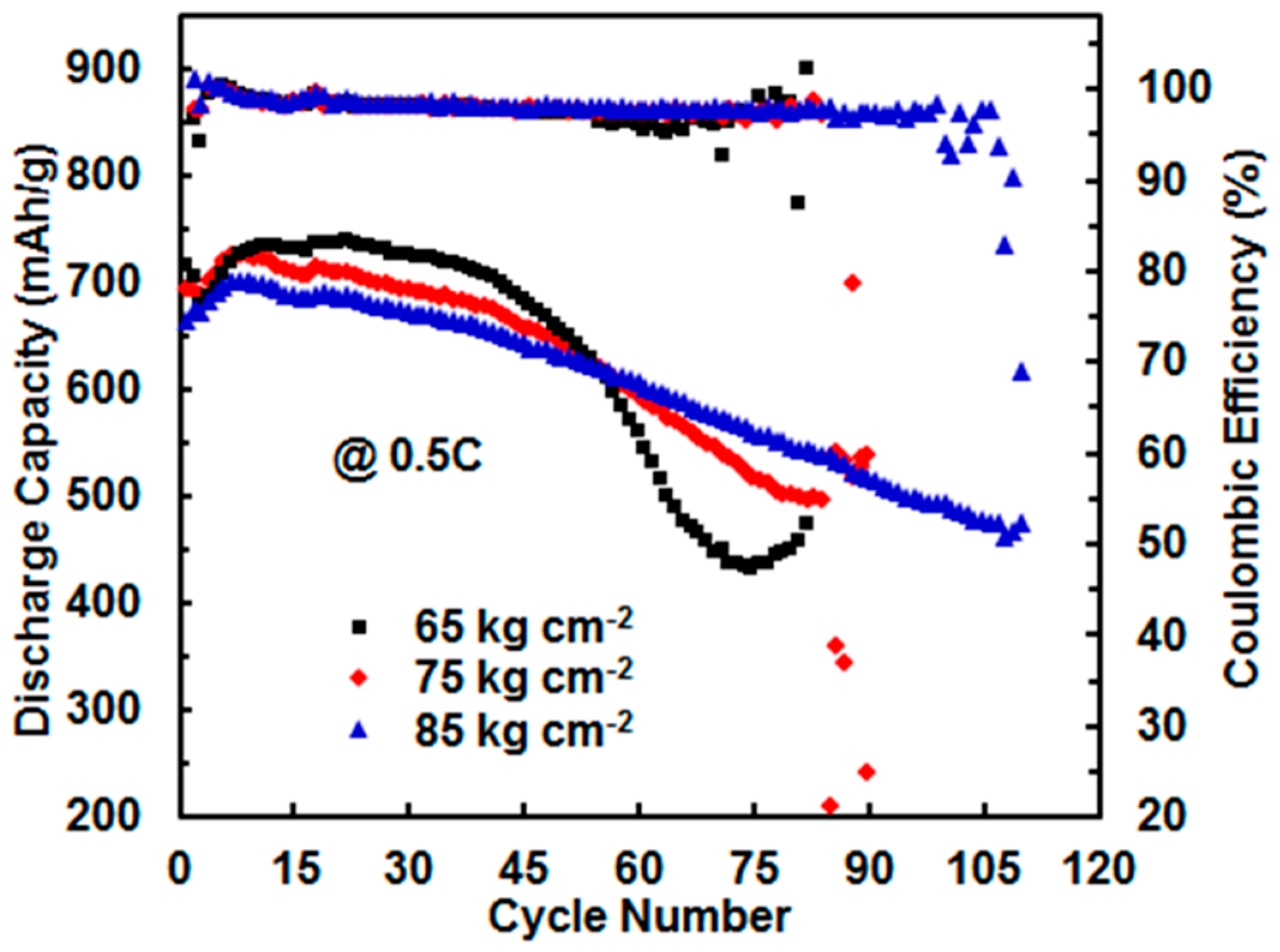
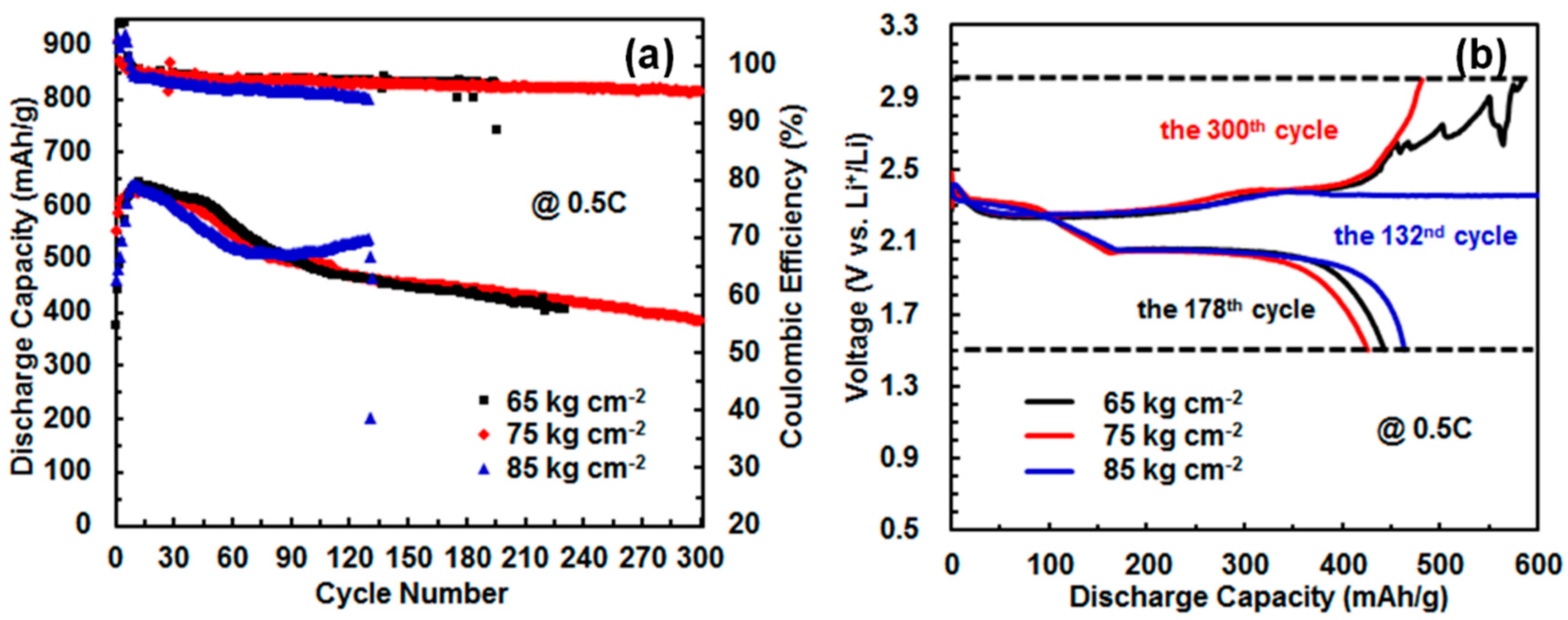
3.2. Effect of Assembling Pressure and Li-Foil Thickness

Following the above results, three cathodes were subsequently fabricated with the use of spring of the optimum thickness of 0.54 mm (Li-foil of 0.6 mm in thickness; 2 sheets of Celgard®2500 separators) by using different coin-cell assembly pressures of 65, 75 and 85 kg cm−2, respectively, to investigate the effect of assembly pressure on the cycling performance of cathodes. Figure 3 shows the specific discharge capacity as a function of cycles at 0.5 C (cut-off voltage, 1.5–3.0 V). With the increase of assembly pressure, there is a small reduction in the initial discharge capacity from 716 to 694 and to 665 mAh g−1. This is accompanied with the significant increase of cycling life of the cathodes from 82 to 90 and to 110 cycles. Meanwhile, the discharge capacity decay is also much lowered with the increase of assembly pressure, with the corresponding decay rates of 0.66%, 0.43%, and 0.31% per cycle (calculated based on the maximum discharge capacity and the capacity in the final cycle), respectively. In particular, the cell assembled at 85 kg cm−2 shows a nearly linear capacity decay, while the one assembled at 65 kg cm−2 has an abrupt capacity drop after about 50 cycles, indicating severe sulfur loss. The above assembly pressure effect is ascribed to the more compact S/C composites at the higher assembly pressure and the less preserved electrolyte [decreasing from 34 μL to 28 μL and to 23 μL with the increasing assembly pressure, corresponding to the electrolyte/sulfur (E/S) ratio from 25.8 to 21.2 and to 17.4 mL g−1, respectively], which help reduce sulfur loss from the cathodes.
Another group of experiments was further designed by changing the thickness of Li-foil. We increased the thickness of Li-foil from 0.60 mm to 1.20 mm. To accommodate this increase in Li-foil thickness, the spring thickness was decreased from 0.54 to 0.18 mm. Cells were also assembled at different assembly pressures, 65, 75, and 85 kg cm−2. The thicker Li-foil was expected to compensate the reduced spring thickness. Meanwhile, we also reason that the thinner spring and the thicker soft Li-foil are beneficial for better buffering the dramatic volume change involved in the cathode over the charge-discharge process [13,40,41,42,43,44,45,46]. In this case, the net increased thickness is 0.24 mm relative to the cells with a spring of 0.54 mm and a Li-foil thickness of 0.60 mm. As shown in Figure 4a, cells fabricated with the thicker Li-foils of 1.20 mm in thickness at 65 kg cm−2 (electrolyte, ca. 32 μL; E/S ratio, 24.2 mL g−1) and 85 kg cm−2 (electrolyte, ca. 23 μL; E/S ratio, 17.4 mL g−1) show a cycling life of 187 and 132 cycles, respectively, whereas that fabricated by using pressure of 75 kg cm−2 (electrolyte, ca. 21 μL; E/S ratio, 15.9 mL g−1) could proceed to >300 cycles though with a gradual decrease of Columbic Efficiency to 95% over cycling (see Figure 4b). Along with the result above (Figure 3), it can be concluded that the cell assembly pressure affects the E/S ratio, which is the underlying parameter essentially affecting the cycling performance of the cell, with improved cycling life achieved at a lowered E/S ratio. Compared to the corresponding cells fabricated with the thinner Li-foil and the thicker spring above, the cycling life data of this set of cells with the thicker Li-foil are significantly improved. However, cells fabricated with the thicker Li-foil show relatively lower discharge capacity (maximum value) compared to, those fabricated correspondingly with the thinner Li-foil (641 vs. 733 mAh g−1, 628 vs. 727 mAh g−1 and 642 vs. 702 mAh g−1) at 65, 75 and 85 kg cm−2, respectively. We reason this results from the increased dead volume within the former cells given the net increased thickness, which leads to reduced effective electrolyte preserved in carbon/sulfur/binder matrix for electrochemical reactions [35].
From this set of cells with the thicker Li-foil, the assembly pressure of 75 kg cm−2 is most optimum in rendering the cell with the lowest E/S ratio and in consequence the longest cycling life. This differs from the cells with the thinner Li-foil, where the optimum assembly pressure is 85 kg cm−2. These data thus indicate that a proper tuning of the geometric parameters of the coil cell components (spring thickness, Li-foil thickness) and the assembly pressure is critical to render better-performing Li–S cells.

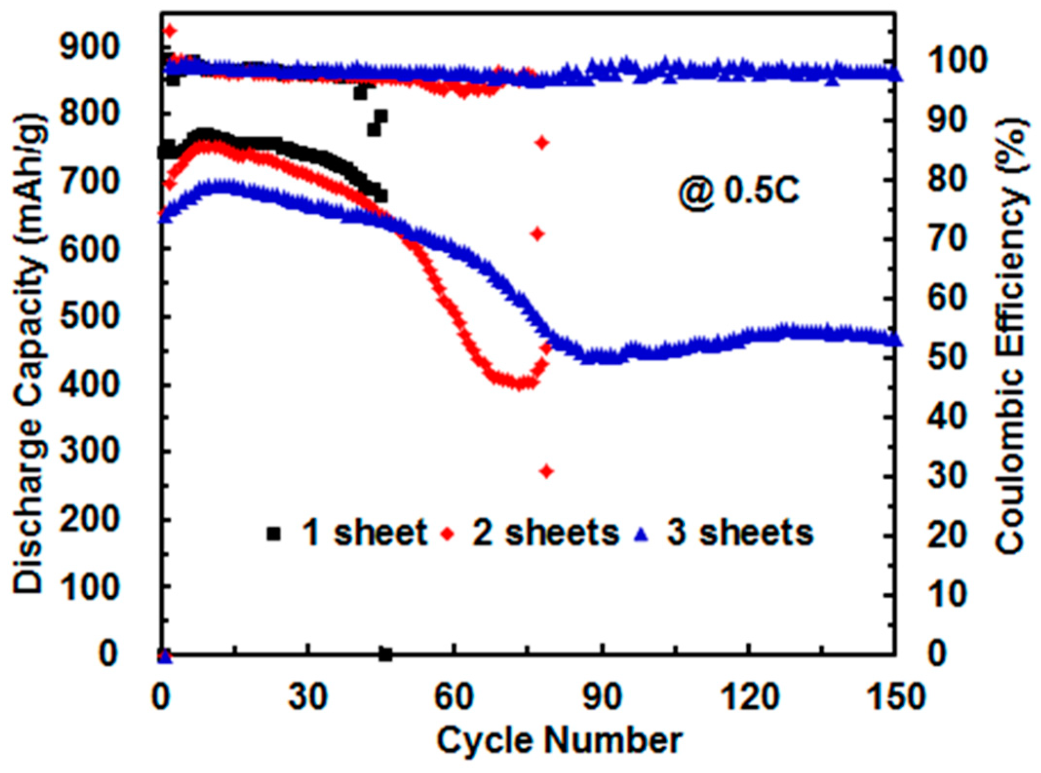
3.3. Effect of Sheet Number of Celgard 2500 Separator

Porous separator [polyethylene (PE), polypropylene (PP)] physically keeps anode and cathode from contacting with each other, while enabling free ionic transport [5,44]. The most commonly used porous separators for Li–S cells are Celgard®2400, Celgard®2500, Celgard®3500, Celgard®3501, Celgard®3401, etc. [5,32,37,41,46] with different pore size and porosity [47]. In literature reports, one sheet of separator is most commonly employed. Hart et al. [37] used two sheets of separators in their work. However, there is no specific study reporting the effect of sheet number of separator (separators stacked together). Herein, we have investigated the effect of sheet number of Celgard®2500 on cell cycling performance. Coin cells were assembled with the 0.60 mm Li-foil and the 0.54 mm spring at the assembly pressure of 65 kg cm−2, but with different sheets (1, 2, and 3) of Celgard®2500. Figure 5 compares the cycling performance of the different cells at 0.5 C. The cells show significantly improved cycling life (41, 65, and 161 cycles) with the increasing sheet number of Celgard®2500. Clearly, the separator can act as the barrier for polysulfide shuttling. Increasing the sheet number can retard the transport of the dissolved polysulfides through the separator to the anode and thus improve the cycling life. However, the Li+ transportation was also hindered upon the increased separator sheet number, which is reflected from the relatively lowered discharge capacity in the first 45 cycles as shown in Figure 5. Therefore, battery kinetics slows down and discharge capacity decreases, which is in agreement with the results reported by Zhu et al. that the separators with greater thicknesses and smaller porosities increase the cell resistances and negatively affect the ionic transportation [48]. Therefore, two sheets of Celgard®2500 are suggested to be the optimum number in the coin cells.

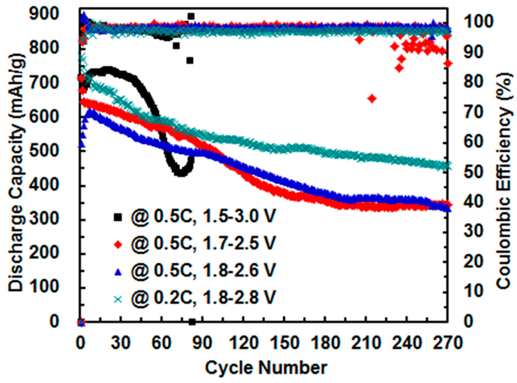
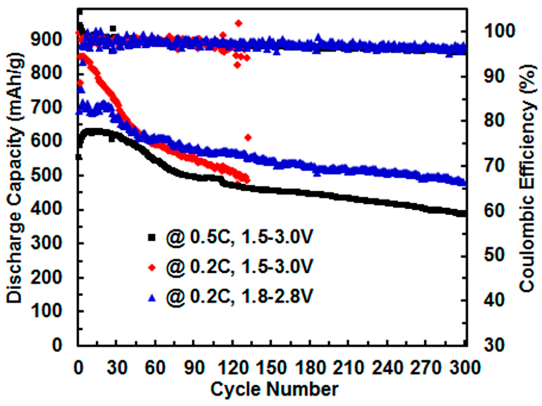
3.4. Effect of Cut-Off Voltage

A narrow electrochemical window (e.g., 1.7–2.5 V) has often been used for the cycling of Li–S cells as an important capacity retention optimization strategy [49], because the electrolyte additive LiNO3 participates in reaction below 1.7 or 1.8 V [36,49]. In addition, a third plateau on the discharge curve can result in the large irreversible capacity loss during the first few cycles [47,50]. Zhang further demonstrates that LiNO3 is capable of catalyzing the conversion of high soluble polysulfide to slightly soluble elemental sulfur near the end of charging process [32]. In addition, Zhang also suggests that the deep discharge must be avoided in order to achieve a long cycle life when LiNO3 is used as an additive or a co-salt of the electrolyte.
To further clarify the effect of the voltage window, cells (fabricated with 0.60 mm Li-foil; 0.54 mm spring; two sheets of Celgard®2500; assembly pressure of 65 kg cm−2) were cycled at different cut-off voltage windows. Figure 6 compares the cycling performance at the different cut-off voltages of 1.5–3.0 V, 1.7–2.5 V and 1.8–2.6 V at 0.5 C. As per Figure 6, the cycling life of the cells within 1.7–2.5 V or 1.8–2.6 V (at 0.5 C) is over 270 cycles, much longer than that (72 cycles) of the cell cycled within 1.5–3.0 V though with unavoidable gradual capacity decay, which is consistent with the results from Zhang [32] and from Nazar et al. [49]. To further illustrate this superior performance, the charge-discharge current was lowered to 0.2 C. As shown in Figure 6, the cell at 0.2 C (1.8–2.8 V) could cycle over 300 cycles with Columbic Efficiency well maintained at about 98%. On the contrary, the cycling life of another cell operated at 0.2 C within 1.5–3.0 V was only 60 cycles. These data thus confirm that the narrower cut-off voltage is indeed beneficial to improve the cycloability of Li–S cells.
Another group of experiments was undertaken on cells fabricated with 1.20 mm Li-foil and 0.18 mm spring (2 sheets of Celgard®2500; assembly pressure of 75 kg cm−2) to investigate the effect of cut-off voltage. From Figure 7, the cell cycled at 0.2 C within 1.5–3.0 V only has a cycle life of 132 cycles as opposed to over 300 cycles at 0.5 C. This behavior agrees well with the results from literatures [13,40] that a higher current rate (0.5 C in this case) can retard the polysulfide shuttling to some degree. When switching to the narrower cut-off voltage of 1.8–2.8 V, the cell can smoothly cycle over 300 cycles at 0.2 C (total charge-discharge cycling life, 40.8 days) with no drastic polysulfide shuttling. Consistent with the above results, this is also suggestive of the narrower cut-off voltage is helpful to enhance the battery cycloability.
Besides the avoidance of LiNO3 consumption below 1.7 V/1.8 V, it is most likely that, within the narrowed voltage windows, less insulated and undissolved Li2S2/Li2S forms [51], enhancing the reversibility of sulfur active material. Results from Figure 6 and Figure 7 demonstrate that polysulfide shuttling can be effectively suppressed by narrowing the cut-off voltage.

4. Conclusions

We have investigated in this work the effects of some “trivial” parameters, including the thicknesses of spring/Li-foil, assembly pressure, sheet number of separator, and cut-off voltage on the cycling performance of Li–S cells. Often ignored in the literature, we have shown that these “trivial” parameters indeed show pronounced, nontrivial effects on the cycling performance of the cells. Optimization of these parameters can synergistically enhance the cycling life. In particular, narrower cut-off voltages (e.g., 1.7–2.5 V and 1.8–2.6 V), as opposed to 1.5–3.0 V, can improve the cycling life to over 300 cycles at 0.2 C. We feel that this work is of value to the practical application of Li–S batteries.

Author Contributions

Z.Y. and J.L. designed the experiments, J.L. performed the experiments; J.L. and Z.Y. analyzed the results and wrote the paper.

Acknowledgments

We thank the funding support from the Canada Research Chair (CRC, Grant #230723) and the Natural Science and Engineering Research Council (NSERC) of Canada (Grant # (#477901-2015).

Conflicts of Interest

The authors declare no conflict of interest.

References

  1. Manthiram, A.; Chung, S.H.; Zu, C. Lithium–sulfur batteries: Progress and prospects. Adv. Mater. 2015, 27, 1980–2006. [Google Scholar] [CrossRef] [PubMed]
  2. Urbonaite, S.; Poux, T.; Novák, P. Progress towards commercially viable Li–S battery cells. Adv. Energy Mater. 2015, 5, 1500118. [Google Scholar] [CrossRef]
  3. Seh, Z.W.; Sun, Y.; Zhang, Q.; Cui, Y. Designing high-energy lithium-sulfur batteries. Chem. Soc. Rev. 2016, 45, 5605–5634. [Google Scholar] [CrossRef] [PubMed]
  4. Rosenman, A.; Markevich, E.; Salitra, G.; Aurbach, D.; Garsuch, A.; Chesneau, F.F. Review on Li–sulfur battery systems: An integral perspective. Adv. Energy Mater. 2015, 5, 150–212. [Google Scholar] [CrossRef]
  5. Bruckner, J.; Thieme, S.; Grossmann, H.T.; Dorfler, S.; Althues, H.; Kaskel, S. Lithium–sulfur batteries: Influence of C-rate, amount of electrolyte and sulfur loading on cycle performance. J. Power Sources 2014, 268, 82–87. [Google Scholar] [CrossRef]
  6. Zhang, S.S. Liquid electrolyte lithium/sulfur battery: Fundamental chemistry, problems, and solutions. J. Power Sources 2013, 231, 153–162. [Google Scholar] [CrossRef]
  7. Rauh, R.D.; Abraham, K.M.; Pearson, G.F.; Surprenant, J.K.; Brummer, S.B. A lithium/dissolved sulfur battery with an organic electrolyte. J. Electrochem. Soc. 1979, 126, A523–A527. [Google Scholar] [CrossRef]
  8. Ji, X.; Lee, K.T.; Nazar, L.F. A highly ordered nanostructured carbon-sulphur cathode for lithium-sulphur batteries. Nat. Mater. 2009, 8, 500–506. [Google Scholar] [CrossRef] [PubMed]
  9. Busche, M.R.; Adelhelm, P.; Sommer, H.; Schneider, H.; Leitner, K.; Janek, J. Systematical electrochemical study on the parasitic shuttle-effect in lithium-sulfur-cells at different temperatures and different rates. J. Power Sources 2014, 259, 289–299. [Google Scholar] [CrossRef]
  10. Urbonaite, S.; Novak, P. Importance of “unimportant” experimental parameters in Li-S battery development. J. Power Sources 2014, 249, 497–502. [Google Scholar] [CrossRef]
  11. Yang, Y.; Zheng, G.; Cui, Y. A membrane-free lithium-polysulfide semi-liquid battery for large-scale energy storage. Energy Environ. Sci. 2013, 6, 1552–1558. [Google Scholar] [CrossRef]
  12. Knap, V.; Stroe, D.I.; Swierczynski, M.; Teodorescu, R.; Schaltz, E. Investigation of the self-discharge behavior of lithium-sulfur batteries. J. Electrochem. Soc. 2016, 163, A911–A916. [Google Scholar] [CrossRef]
  13. Liu, M.; Li, Q.; Qin, X.; Liang, G.; Han, W.; Zhou, D.; He, Y.B.; Li, B.; Kang, F. Suppressing self-discharge and shuttle effect of lithium-sulfur batteries with V2O5-decorated carbon nanofiber interlayer. Small 2017, 13, 1602539. [Google Scholar] [CrossRef] [PubMed]
  14. Cheng, X.B.; Huang, J.Q.; Peng, H.J.; Nie, J.Q.; Liu, X.Y.; Zhang, Q.; Wei, F. Polysulfide shuttle control: Towards a lithium-sulfur battery with superior capacity performance up to 1000 cycles by matching the sulfur/electrolyte loading. J. Power Sources 2014, 253, 263–268. [Google Scholar] [CrossRef]
  15. Li, Z.; Deng, S.; Li, H.; Ke, H.; Zeng, D.; Zhang, Y.; Sun, Y.; Cheng, H. Explore the influence of coverage percentage of sulfur electrode on the cycle performance of lithium-sulfur batteries. J. Power Sources 2017, 347, 238–246. [Google Scholar] [CrossRef]
  16. Li, Z.; Huang, Y.; Yuan, L.; Hao, Z.; Huang, Y. Status and prospects in sulfur-carbon composites as cathode materials for rechargeable lithium-sulfur batteries. Carbon 2015, 92, 41–63. [Google Scholar] [CrossRef]
  17. Pang, Q.; Liang, X.; Kwok, C.Y.; Nazar, L.F. Advances in Lithium-sulfur batteries based on multifunctional cathodes and electrolytes. Nat. Energy 2016, 1, 16132. [Google Scholar] [CrossRef]
  18. Yang, Y.; Zheng, G.; Cui, Y. Nanostructured sulfur cathodes. Chem. Soc. Rev. 2013, 42, 3018–3032. [Google Scholar] [CrossRef] [PubMed]
  19. Rehman, S.; Khan, K.; Zhao, Y.; Hou, Y. Nanostructured cathode materials for lithium-sulfur batteries: Progress, challenges and perspectives. J. Mater. Chem. A 2017, 5, 3014–3038. [Google Scholar] [CrossRef]
  20. Xu, C.; Wu, Y.; Zhao, X.; Wang, X.; Du, G.; Zhang, J.; Tu, J. Sulfur/three-dimensional graphene composite for high performance lithium-sulfur batteries. J. Power Sources 2015, 275, 22–25. [Google Scholar] [CrossRef]
  21. Zhang, J.; Shi, Y.; Ding, Y.; Zhang, W.; Yu, G. In situ reactive synthesis of polypyrrole-MnO2 coaxial nanotubes as sulfur hosts for high-performance lithium-sulfur battery. Nano Lett. 2016, 16, 7276–7281. [Google Scholar] [CrossRef] [PubMed]
  22. Zhang, J.; Shi, Y.; Ding, Y.; Peng, L.; Zhang, W.; Yu, G. A conductive molecular framework derived Li2S/N,P-codoped carbon cathode for advanced lithium-sulfur batteries. Adv. Energy Mater. 2017, 7, 1602876. [Google Scholar] [CrossRef]
  23. Zhang, J.; Huang, H.; Bae, J.; Chung, S.H.; Zhang, W.; Manthiram, A.; Yu, G. Nanostructured host materials for trapping sulfur in rechargeable Li-S batteries: Structure design and interfacial chemistry. Small Methods 2017, 1700279. [Google Scholar] [CrossRef]
  24. Lim, S.; Thankamony, R.L.; Yim, T.; Chu, H.; Kim, Y.J.; Mun, J.; Kim, T.Y. Surface Modification of sulfur electrodes by chemically anchored cross-linked polymer coating for lithium-sulfur batteries. ACS Appl. Mater. Interfaces 2015, 7, 1401–1405. [Google Scholar] [CrossRef] [PubMed]
  25. Li, Y.; Yuan, L.; Li, Z.; Qi, Y.; Wu, C.; Liu, J.; Huang, Y. Improving the electrochemical performance of a lithium-sulfur battery with a conductive polymer coated sulfur cathode. RSC Adv. 2015, 5, 44160–44164. [Google Scholar] [CrossRef]
  26. Lee, J.; Hwang, T.; Lee, Y.; Lee, J.K.; Choi, W. Coating of sulfur particles with manganese oxide nanowires as a cathode material in lithium–sulfur batteries. Mater. Lett. 2015, 158, 132–135. [Google Scholar] [CrossRef]
  27. Huang, J.Q.; Zhang, Q.; Wei, F. Multi-functional separator/interlayer system for high-stable lithium-sulfur batteries: Progress and prospects. Energy Storage Mater. 2015, 1, 127–145. [Google Scholar] [CrossRef]
  28. Xu, G.; Yan, Q.B.; Kushima, A.; Zhang, X.; Pan, J.; Li, J. Conductive graphene oxide-polyacrylic acid (GOPAA) binder for lithium–sulfur battery. Nano Energy 2017, 31, 568–574. [Google Scholar] [CrossRef]
  29. Chen, W.; Qian, T.; Xiong, J.; Xu, N.; Liu, X.J.; Liu, J.; Zhou, J.; Shen, X.; Yang, T.; Chen, Y.; et al. A new type of multifunctional polar binder: Toward practical application of high energy lithium sulfur batteries. Adv. Mater. 2017, 29, 1605160. [Google Scholar] [CrossRef] [PubMed]
  30. Milroy, C.; Manthiram, A. An Elastic, conductive, electroactive nanocomposite binder for flexible sulfur cathodes in lithium-sulfur batteries. Adv. Mater. 2016, 28, 9744. [Google Scholar] [CrossRef] [PubMed]
  31. Aurbach, D.; Pollak, E.; Elazari, R.; Salitra, G.; Kelley, C.S.; Affinito, J. On the surface chemical aspects of very high energy density, rechargeable Li–sulfur batteries. J. Electrochem. Soc. 2009, 156, A694–A702. [Google Scholar] [CrossRef]
  32. Zhang, S.S. A new finding on the role of LiNO3 in lithium-sulfur battery. J. Power Sources 2016, 322, 99–105. [Google Scholar] [CrossRef]
  33. Barchasz, C.; Leprêtre, J.C.; Alloin, F.; Patoux, S. New insights into the limiting parameters of the Li–S rechargeable cell. J. Power Sources 2012, 199, 322–330. [Google Scholar] [CrossRef]
  34. Gao, J.; Lowe, M.A.; Kiya, Y.; Abrunña, H.D. Effects of liquid electrolytes on the charge discharge performance of rechargeable lithium/sulfur batteries: Electrochemical and in-situ X-ray absorption spectroscopic studies. J. Phys. Chem. C 2011, 115, 25132–25137. [Google Scholar] [CrossRef]
  35. Zhang, S.S. Improved cyclability of liquid electrolyte lithium/sulfur batteries by optimizing electrolyte/sulfur ratio. Energies 2012, 5, 5190–5197. [Google Scholar] [CrossRef]
  36. Zhang, S.S. Effect of discharge cutoff voltage on reversibility of lithium/sulfur batteries with LiNO3-contained electrolyte. J. Electrochem. Soc. 2012, 159, A920–A923. [Google Scholar] [CrossRef]
  37. Ding, N.; Chien, S.W.; Andy Hor, T.S.; Liu, Z.; Zong, Y. Key parameters in design of lithium sulfur batteries. J. Power Sources 2014, 269, 111–116. [Google Scholar] [CrossRef]
  38. Gao, J.; Abrunña, H.D. Key parameters governing the energy density of rechargeable Li/S batteries. J. Phys. Chem. Lett. 2014, 5, 882–885. [Google Scholar] [CrossRef] [PubMed]
  39. Liao, J.; Ye, Z. Quaternary ammonium cationic polymer as a superior bifunctional binder for lithium-sulfur batteries and effects of counter anion. Electrochim. Acta 2017, 259, 626–636. [Google Scholar] [CrossRef]
  40. Mikhaylik, Y.V.; Akridge, J.R. Polysulfide shuttle study in the Li/S battery system. J. Electrochem. Soc. 2004, 151, A1969–A1976. [Google Scholar] [CrossRef]
  41. Hart, C.J.; Cuisinier, M.; Liang, X.; Kundu, D.; Garsuch, A.; Nazar, L.F. Rational design of sulphur host materials for Li-S Batteries: Correlating lithium polysulphide adsorptivity and self-discharge capacity loss. Chem. Commun. 2015, 51, 2308–2311. [Google Scholar] [CrossRef] [PubMed]
  42. Moy, D.; Manivannan, A.; Narayanana, S.R. Direct measurement of polysulfide shuttle current: A window into understanding the performance of lithium-sulfur cells. J. Electrochem. Soc. 2015, 162, A1–A7. [Google Scholar] [CrossRef]
  43. Wu, F.; Kim, H.; Magasinski, A.; Lee, J.T.; Lin, H.T.; Yushin, G. Harnessing steric separation of freshly nucleated Li2S nanoparticles for bottom-up assembly of high-performance cathodes for lithium-sulfur and lithium-ion batteries. Adv. Energy Mater. 2014, 4, 140–196. [Google Scholar] [CrossRef]
  44. Wang, Q.; Yan, N.; Wang, M.; Qu, C.; Yang, X.; Zhang, H.; Li, X.; Zhang, H. Layer-by-layer assembled C/S cathode with trace binder for Li-S battery application. ACS Appl. Mater. Interfaces 2015, 7, 25002–25006. [Google Scholar] [CrossRef] [PubMed]
  45. Tang, Q.; Shan, Z.; Wang, L.; Qin, X.; Zhu, K.; Tian, J.; Liu, X. Nafion coated sulfur-carbon electrode for high performance lithium-sulfur batteries. J. Power Sources 2014, 246, 253–259. [Google Scholar] [CrossRef]
  46. Pan, J.; Xu, G.; Ding, B.; Chang, Z.; Wang, A.; Dou, H.; Zhang, X. PAA/PEDOT: PSS as a multifunctional, water soluble binder to improve the capacity and stability of lithium–sulfur batteries. RSC Adv. 2016, 6, 40650–40655. [Google Scholar] [CrossRef]
  47. Yang, M.; Hou, J. Membranes in lithium ion batteries. Membranes 2012, 2, 367–383. [Google Scholar] [CrossRef] [PubMed]
  48. Zhu, J.; Yanilmaz, M.; Fu, K.; Chen, C.; Lu, Y.; Ge, Y.; Kim, D.; Zhang, X. Understanding glass fiber membrane used as a novel separator for lithium-sulfur batteries. J. Membr. Sci. 2016, 504, 89–96. [Google Scholar] [CrossRef]
  49. He, G.; Hart, C.J.; Liang, X.; Garsuch, A.; Nazar, L.F. Stable cycling of a scalable graphene-encapsulated nanocomposite for lithium-sulfur batteries. ACS Appl. Mater. Interfaces 2014, 6, 10917–10923. [Google Scholar] [CrossRef] [PubMed]
  50. Su, Y.S.; Fu, Y.; Manthiram, A. Self-weaving sulfur-carbon composite cathodes for high rate lithium-sulfur batteries. Phys. Chem. Chem. Phys. 2012, 14, 14495–14499. [Google Scholar] [CrossRef] [PubMed]
  51. Hong, X.; Jin, J.; Wen, Z.; Zhang, S.; Wang, Q.; Shen, C.; Rui, K. On the dispersion of lithium-sulfur battery cathode materials effected by electrostatic and stereo-chemical factors of binders. J. Power Sources 2016, 324, 455–461. [Google Scholar] [CrossRef]
Figure 1. Illustration of a CR2032-type Li–S coin cell assembly, and the repeat unit structures of polydiallyldimethylammonium (PDADMA-T) and poly(vinylidene fluoride) (PVDF).
Batteries 04 00022 g001
Figure 2. (a) Cycling performance (cut-off voltage: 1.5–3.0 V, at 0.5 C) and (b) final cycle charge-discharge curves of cells fabricated with springs of 0.36 and 0.54 mm in thickness and with different binders (PDADMA-T and PVDF).
Batteries 04 00022 g002
Figure 3. Cycling performance of cells (PDADMA-T as the binder) fabricated by using assembly pressure of 65, 75 and 85 kg cm−2 at 0.5 C, respectively. Cut-off voltage: 1.5–3.0 V.
Batteries 04 00022 g003
Figure 4. (a) Cycling performance (cut-off voltage: 1.5–3.0 V at 0.5 C) and (b) final cycle charge-discharge curves of Li–S cells fabricated with 1.20 mm Li-foil (PDADMA-T as the binder) at different assembly pressures of 65, 75 and 85 kg cm−2, respectively.
Batteries 04 00022 g004
Figure 5. Cycling performance (cut-off voltage: 1.5–3.0 V at 0.5 C) of Li–S cells fabricated with one, two, and three sheets of separators, respectively (0.60 mm Li-foil; 0.54 mm spring; 65 kg cm−2 assembly pressure).
Batteries 04 00022 g005
Figure 6. Cycling performance of Li–S batteries (PDADMA-T as the binder) using different cut-off voltages (1.5–3.0 V, 1.7–2.5 V, 1.8–2.6 V). Assembly pressure, 65 kg cm−2; spring, 0.54 mm in thickness; Li-foil, 0.60 mm in thickness.
Batteries 04 00022 g006
Figure 7. Cycling performance of Li–S cells (fabricated with 0.18 mm spring, 1.20 mm Li-foil, 2 sheets of separator, and assembly pressure, 75 kg cm−2) using cut-off voltages of 1.5–3.0 V and 1.8–2.8 V, respectively.
Batteries 04 00022 g007

