Article

Automated Crude Constituent Extractor for Partitioning of Refined Crude and Extraction and Distribution of Individual Constituents

by
Godall Rohi
1,2,
Warrior Ofualagba
1,2,
Esere Ejofodomi
2,
O’tega Ejofodomi
1,2,*,
Godswill Ofualagba
1,2 and
El Elyon Tsidkenu
1,2
1
Racett Canada Inc., 404 St George Street, Moncton, NB E1C 1X0, Canada
2
Racett Nigeria Ltd., Zone 8, FCT, Abuja 90001, Nigeria
*
Author to whom correspondence should be addressed.
Designs 2018, 2(3), 22; https://doi.org/10.3390/designs2030022
Submission received: 28 March 2018 / Revised: 23 June 2018 / Accepted: 25 June 2018 / Published: 30 June 2018

Abstract

:
The current extraction process in the Oil and Gas Industry today takes 10–32 h for 2 tonnes of refined crude, incurs 16–25% of the total volume spill, has an extraction efficiency of 50–74%, experiences $820—$4250 CAD of revenue loss for every 1% spilled and costs $280,000–$650,000 CAD to clean up a single percent. The Automated Crude Constituent Extractor extracts constituents from 2 tonnes of refined crude in 34–46 min, incurs no volume spill, has an extraction efficiency of 76–98%, results in no revenue loss and no remediation cost. This system needs to be implemented immediately in the Oil and Gas Industry today so that oil producing nations can start enjoying these benefits.

1. Introduction

Crude oil and its constituents/components has key uses in our society today. The Petrol, a refined component of crude oil, is used to fuel our cars and other automobiles. Diesel, another constituent of crude oil, is used to provide electricity, heating, lighting and for cooking in our homes and societies. Kerosene, a component of crude oil, is used for heating, lighting and cooking in our society. It is therefore, imperative, that the process of extracting the components of crude oil is well understood and implemented and this process is typically carried out by the Oil and Gas industry. This paper explains the process of extracting the components of crude oil currently in used in our Oil and Gas Industry and presents new innovative techniques to ensure that this process is performed exceptionally.
The extraction of the constituents of crude oil is a manual and labor-intensive process in almost all countries (see Figure 1). Refined crude oil is first shipped in large vessels on tankers to extraction sites where they are unloaded and the extraction process begins. Crude oil packages are tagged so the extractors know which company it belongs to. Companies typically request for one constituent to be extracted (72%), sometimes two (26%) and a maximum of three constituents (2%). The vast majority request for the petrol constituent (84%), followed by diesel (15%) and then dross (1%) [1,2].
For the petrol, the crude is transferred into a cooking barrel and baked for four (4) h at 450 °C. After this, it is left in the barrel for four hours to cool down to 200 °C using fans. The fans come on automatically as soon as the baking is completed. At 200 °C, the petrol is transferrable. It is poured very slowly into other containers so the heat gives off, one container at a time. Using this process, the temperature drops to about 120 °C and takes two hours. Using steel re-enforced pipes, they are able to transport this 120 °C petrol to final customers.
For the diesel, our crude is transferred into a cooking barrel and baked for six (6) h at 850 °C. After this, it is left in the barrel for eight (8) h and it cools down to 450 °C. Once again, the fans for cooling come on automatically as soon as baking is completed. At 450 °C, the diesel is still too hot to be transferred, so it is shifted to the side by eighteen strong men and left to cool with a second fan that comes on automatically (due to pre-set time interval based on first fan’s activation). The diesel stays at this fan until it cools down to 85 °C. Once this happens, the fan is switched off and the diesel is transferred into another shipment container and then it is sent off to the final customers.
For the dross, our crude is transferred into a cooking barrel and baked for six (6) h at 500 °C. After this, it is shifted to the side and the cooling fans come on automatically to cool the dross down to 70 °C in 12 h. When this happens, twenty men start scooping the surface mixture into another barrel using kegs until it is just the dross at the bottom. This barrel is a shipment container for diesel as this liquid is diesel (dross-diesel). The men then proceed to excavate the dross with their bare hands. Essentially, it is murky and time-consuming and shapeless and it takes fourteen (14) h to empty the cooled down barrel of the dross. The dross is emptied into shipment containers and is sent off to the final consumers. The final burnt dross at the bottom of the barrel is scraped out. For each of the processes, the maximum tonne capacity at any given time is 8 tonnes [1]. Each process is done in two-tonne batches.
The total time for petrol, diesel, dross-diesel and dross extraction is ten hours, twelve hours, twelve hours and thirty-two hours respectively and the fire for the baking is provided using firewood and petrol manually. Using the firewood, there is at least one case of accidental burn for a refinery every week [1]. For Nigeria, the rate of accidental burns is at least one case every single day [2]. In addition to this, there is volume loss incurred at every stage of the extracting process (see Table 1). This environmental pollution occurs during the extraction process that adversely affects the environmental and the health of the workers involved and the people living within that region [3,4,5,6,7,8] and this needs to be addressed [9,10,11].
This loss in volume results in a national revenue loss of $4250 CAD, $3275 CAD, $2960 CAD and $820 for Petrol, Diesel, Dross-Diesel and Dross respectively. For Nigeria, the loss in volume results in a national revenue loss of ₦1,285,000, ₦975,000, ₦825,000 and ₦650,000 for Petrol, Diesel, Dross-Diesel and Dross respectively. There are better methods that can be employed to improve the extraction of the constituents of the crude oil from the source. In this paper, we present an Automated Crude Constituent Extractor for partitioning of refined crude into the volumes specified by the customer for the different desired constituents and also for the automated extraction of the constituents from the partitioned crude, before automatic shipping to the final consumers.
Using current methods, 86% of the volume of a refined crude shipment can be extracted as petrol, 76% can be extracted as Diesel, 62% can be extracted as Dross-Diesel and 60% as Dross [1]. For Nigeria, using current methods, 76% of the volume of a refined crude shipment can be extracted as Petrol, 68% can be extracted as Diesel, 58% as Kerosene, 49% as Good Quality Diesel and 50% as Dross [2].
Using the Automated Crude Constituent Extractor in this paper, 98% of the volume of a refined crude shipment can be extracted as petrol, 97% can be extracted as Diesel, 98% as Kerosene, 76% as Good Quality Diesel and 98% as Dross.
The materials needed to construct the Automated Crude Constituent Extractor is listed in the Material and Methods Section. The principle and process of operation is explained in the Methods Section. The performance data of the system is shown in the Results Section. The key benefits and advantages of the Automated Crude Constituent Extractor are explained in detail in the Discussion Section and the steps to ensuring the physical implementation of the system is summarized in the Conclusion Section.

2. Materials and Methods

2.1. Materials

The materials required to physically construct the Automated Crude Constituent Extractor is listed below:
  • XBee and Antenna
  • Xbee shields
  • GSM/GPRS/GPS Shield
  • Arduino Mega
  • Custom Cases
  • Pipeline Batteries
  • Batteries
  • LCD Displays
  • AA Batteries
  • Pipeline Valves
  • Refined Crude pipelines
  • Constituent Pipelines
  • 38-inch heating turns for Automated Crude Constituent Extractors
  • 30-inch cooling Turns for Automated Crude Constituent Extractors
  • Extracting Receptacles
  • Pipeline Refining Filters
  • Dross Spade Removal
  • Automated Overhead Fans
  • Automated Cooling Conveyor Belts
  • Automated Crude Transporters
  • Receptacle Internal Batteries
  • Temperature Sensors
  • Level Sensors
  • Submersible Receptacle Volume Estimators.

2.2. Methods

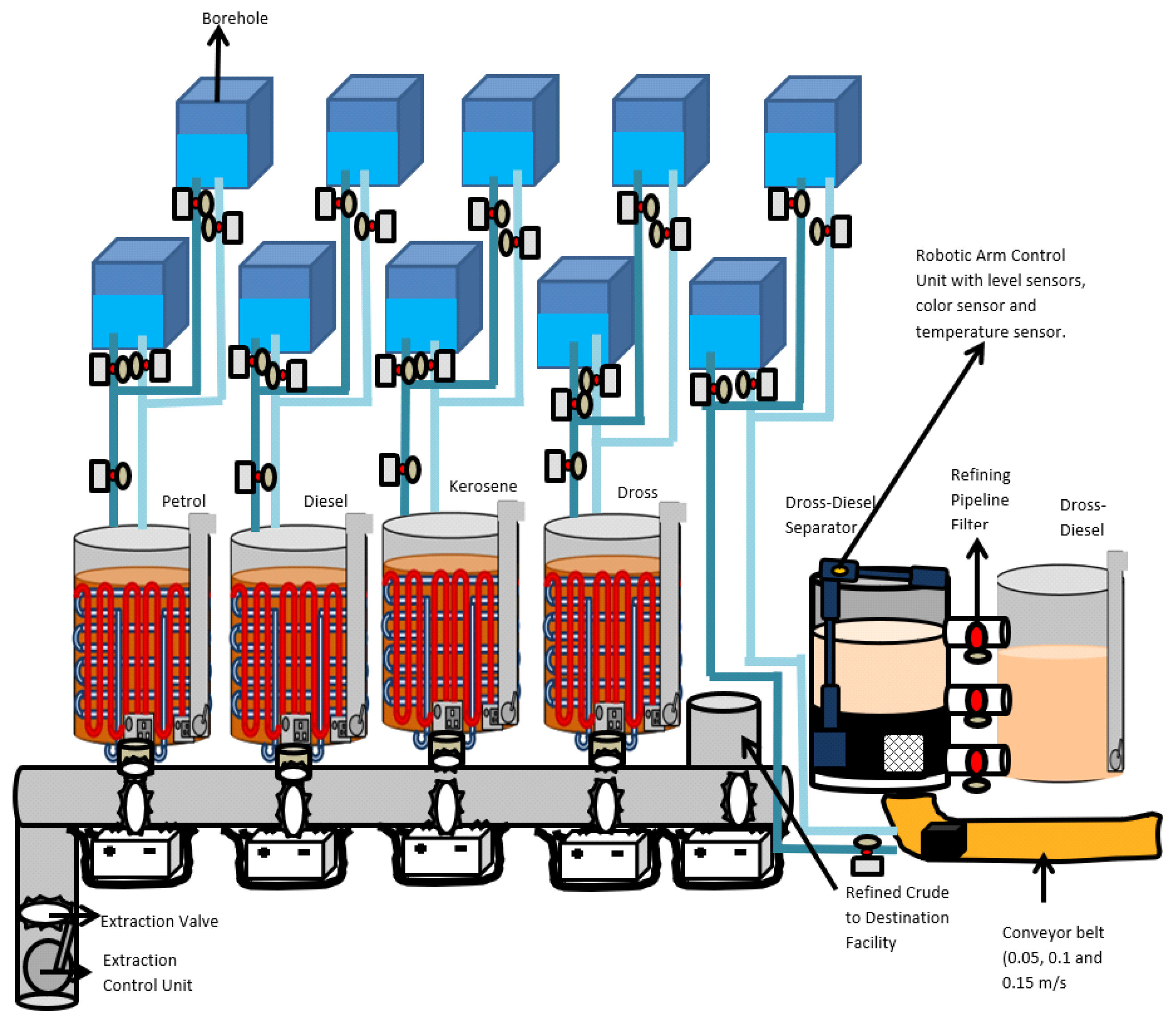
The Automated Crude Constituent Extractor is meant to be used in tandem with the Automated Refiner, Receptacle Volume Estimators (Air and Submersible) and Automated Crude Transporters to form a fully automated refinery. However, it can be used separately by itself by people and companies who are solely interested in extracting the components of crude and are not interested in the refining process. For these people, the refined crude is shipped or transported directly to their extraction site and the automated Crude Constituent Extractor can perform the extraction for them. They are also at liberty to select and install one, two, three or all (four) of the individual extractors that comprise the Automated Crude Constituent Extractor. The full Automated Crude Constituent Extractor is shown in Figure 2. The Extraction Control Unit can be used to determine the content of different components of the mixture based on the chemical signature detectors built into it. The unit also ensures that mixture flow through valves remain uncompromised because pump speed is selected based on the natural viscosity of the liquid. The effect of viscosity will be explored during prototype development.
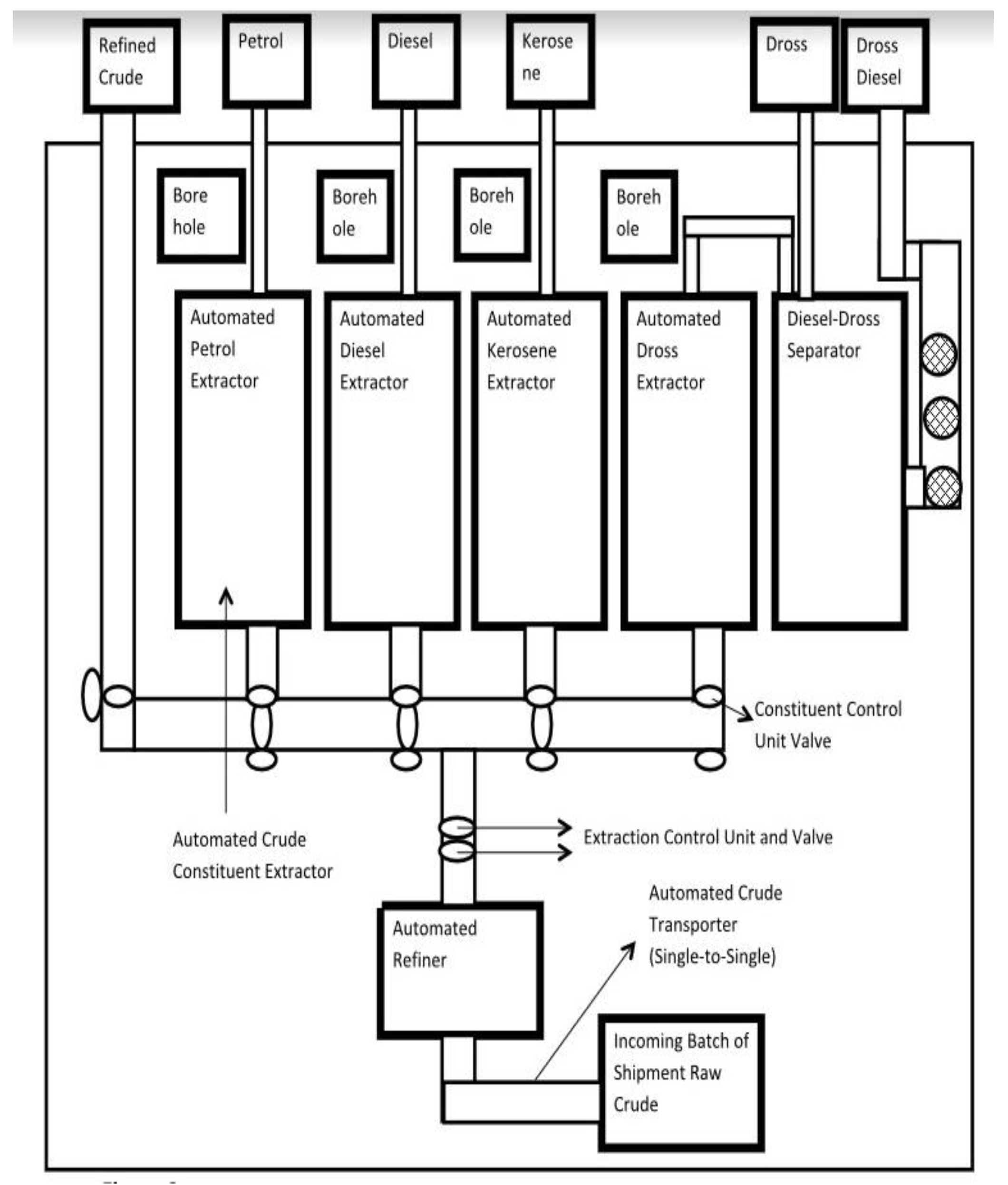
For a fully automated refinery (see Figure 3), the Extracting Control Unit is informed of the percentage of the refined crude volume to be sent to each Individual Extractor within the crude Constituent Extractor through an incoming text message that is received from the Submersible Receptacle Volume Estimator for Incoming Crude into the Automated Refiner. This message is received from the destination facility prior to the raw crude being shipped into the refinery.
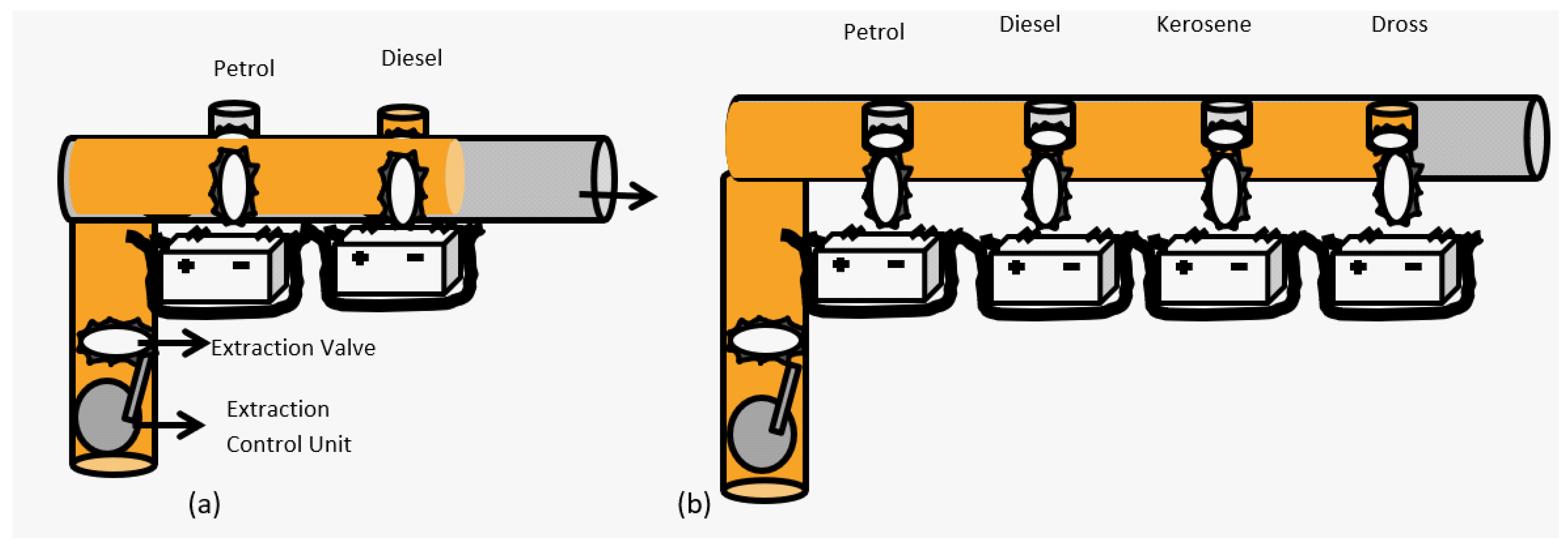
For companies with extraction processes only, the Extracting Control Unit, when switched on automatically asks the user to enter in the total volume of refined crude for extraction, the percentage of the refined crude to be broken down into petrol, diesel, kerosene and dross. For a particular crude oil shipment does not require the extraction of a constituent, zero percent (0%) is entered for that constituent After this the extraction control unit automatically switches on an automated pump to start pumping the refined crude into the various extractors, in the case of extractor processes only (see Figure 4). For the fully automated refinery, there is a fifth constituent for which the extracting control unit asks the user to specify a percentage. That constituent is the refined crude oil itself and it leaves the user with the ability to export crude oil from his or her refinery as well as its constituents.
After entering the percentages, the extraction unit then sends an activation message to the refined crude valve control unit, causing it to alter its power supply and open the valves (RC1 and RC2) for the refined crude to enter into the export pipe for refined crude. The extraction control unit constantly monitors the time of dispatch and the flow rate and calculates the volume of refined crude being exported. When this volume is equivalent to the specified percentage of the total volume for the crude constituent, a shut off message is sent by the extraction control unit to the refined crude control unit, causing it to automatically alter the power supply to its valves (RC1 and RC2), shutting the valves and ceasing dispense to the refined crude export pipe. If the required percentage of the refined crude is 0%, no message is sent to the refined crude control unit and the extractor unit moves on to the next constituent.
For both the fully automated refinery and the extraction only process companies, the extractor unit checks the user required percentage for petrol. If it is zero, it does nothing. If it is greater than zero, it sends an activation message to the petrol valve control unit, causing that one to alter its power supply to open its valves (P1 and P2) and allow the flowing refined crude to enter into the petrol pipe and from there into the Extracting Receptacle of the automated Petrol Extractor. The extraction control unit constantly monitors the time of dispatch and the flow rate and calculates the volume of refined crude flowing into the extracting receptacle until it is equivalent to the user-specified percentage of the total volume for the crude oil shipment and then it sends a shut off message to the petrol control unit, causing that one to automatically alter the power supply to its valves (P1 and P2), shutting them off and ceasing flow of refined crude into the extracting Receptacle. The extraction control unit then checks for the user required percentage for diesel. Nothing is done if it is 0%. Otherwise, it sends an activation message to the diesel valve control unit, causing it to alter its power supply to open the valves (D1 and D2) and allow the flowing refined crude to enter into the diesel pipe and on to the Extracting Receptacle of the Automated Diesel Extractor. The extraction control unit constantly monitors the time of dispatch and the flow rate and calculates the volume of refined crude flowing into the extracting receptacle until it is equivalent to the user-specified percentage of the total volume for the crude oil shipment and then it sends a shut off message to the diesel control unit, causing that one to automatically alter the power supply to its valves (D1 and D2), shutting them off and ceasing flow of refined crude into the Extracting Receptacle.
The extraction control unit then checks for the user required percentage for kerosene. Nothing is done if it is 0%. Otherwise, it sends an activation message to the kerosene valve control unit, causing it to alter its power supply to open the valves (K1 and K2) and allow the flowing refined crude to enter into the kerosene pipe and on to the Extracting Receptacle of the Automated Kerosene Extractor. The extraction control unit constantly monitors the time of dispatch and the flow rate and calculates the volume of refined crude flowing into the extracting receptacle until it is equivalent to the user-specified percentage of the total volume for the crude oil shipment and then it sends a shut off message to the kerosene control unit, causing that one to automatically alter the power supply to its valves (K1 and K2), shutting them off and ceasing flow of refined crude into the Extracting Receptacle.
Finally, the extraction control unit then checks for the user required percentage for dross. Nothing is done if it is 0%. Otherwise, it sends an activation message to the dross valve control unit, causing it to alter its power supply to open the valves (D1 and D2) and allow the flowing refined crude to enter into the kerosene pipe and on to the Extracting Receptacle of the Automated Dross Extractor. The extraction control unit constantly monitors the time of dispatch and the flow rate and calculates the volume of refined crude flowing into the extracting receptacle until it is equivalent to the user-specified percentage of the total volume for the crude oil shipment and then it sends a shut off message to the dross control unit, causing that one to automatically alter the power supply to its valves (D1 and D2), shutting them off and ceasing flow of refined crude into the Extracting Receptacle.
After this, the extraction control unit alters the power supply to its own valve, closing it as the entire volume of the crude oil shipment has been sent into the automated crude Constituent Extractor.
An individual extractor consists of an extracting receptacle with 38-inch diameter heating turns arranged in a cylindrical fashion within its walls, a 30-inch diameter cooling turns arranged in circular fashion within its walls and connected externally to two automated boreholes for automated cooling of the extracted crude constituent. A submersible Receptacle Volume Estimator automatically measures the volume of refined crude deposited into the Extracting Receptacle of the automated Petrol Extractor. Once deposition is complete, the submersible receptacle volume estimator sends an activation message to the heating control unit of the Extracting Receptacle, altering the power supply to the heating turns and causing them to heat the refined crude contained within the receptacle to 450 °C via the processes of conduction and convection. This temperature is maintained for twelve minutes in order to convert the refined crude to petrol and then the estimator sends another message to the heating control unit to alter and switch off its power supply. After extraction, the estimator sends an activation message to the cooling control unit of the Extracting Receptacle, which in turn sends a cooling message to the inlet and outlet valves of the automatically selected borehole with room temperature (23 °C) water, causing both valves to open and activating the automated pump to begin pumping the room temperature water from the borehole into the inlet pipe and into the cooling turns of the extracting Receptacle before flowing out into the outlet pipe and back into the selected bore hole. This process cools the extracted petrol from 450 to 70 °C in seven minutes. After this time interval, the cooling control unit sends a shutdown message to the inlet and outlet valve control unit of the selected borehole, causing the inlet pipe to first shut off due to change in its power supply to cease water from flowing into the extracting Receptacle and then shutting off the outlet pipe to shut off a full minute later by changing its power supply to ensure all the water is locked back into the bore hole. The cooling control unit of the Petrol Extractor automatically selects the other borehole for the next batch of petrol extraction, as it takes 6 min for borehole whose water has been used to cool down extracted petrol to return to 23 °C after rising to 67 °C. The extracted petrol is then pumped automatically out of the Extracting Receptacle of the Automated Petrol Extractor to the export pipe, leading to the final consumers using an automated crude transporter.
A Submersible Receptacle Volume Estimator automatically measures the volume of refined crude deposited into the Extracting Receptacle of the automated diesel Extractor. Once deposition is complete, the submersible receptacle volume estimator sends an activation message to the heating control unit of the Extracting Receptacle, altering the power supply to the heating turns and causing them to heat the refined crude contained within the receptacle to 850 °C via the processes of conduction and convection. This temperature is maintained for twelve minutes in order to convert the refined crude to diesel and then the estimator sends another message to the heating control unit to alter and switch off its power supply. After extraction, the estimator sends an activation message to the cooling control unit of the Extracting Receptacle, which in turn sends a cooling message to the inlet and outlet valves of the automatically selected borehole with room temperature (23 °C) water, causing both valves to open and activating the automated pump to begin pumping the room temperature water from the borehole into the inlet pipe and into the cooling turns of the extracting Receptacle before flowing out into the outlet pipe and back into the selected bore hole. This process cools the extracted diesel from 850 to 80 °C in four minutes. After this time interval, the cooling control unit sends a shutdown message to the inlet and outlet valve control unit of the selected borehole, causing the inlet pipe to first shut off due to change in its power supply to cease water from flowing into the extracting receptacle and then shutting off the outlet pipe to shut off a full minute later by changing its power supply to ensure all the water is locked back into the bore hole. The cooling control unit of the Diesel Extractor automatically selects the other borehole for the next batch of diesel extraction, as it takes 8 min for borehole whose water has been used to cool down extracted diesel to return to 23 °C after rising to 87 °C. The extracted diesel is then pumped automatically out of the Extracting Receptacle of the Automated Diesel Extractor to the export pipe, leading to the final consumers using an automated crude transporter.
A Submersible Receptacle Volume Estimator automatically measures the volume of refined crude deposited into the Extracting Receptacle of the automated kerosene extractor. Once deposition is complete, the submersible receptacle volume estimator sends an activation message to the heating control unit of the Extracting Receptacle, altering the power supply to the heating turns and causing them to heat the refined crude contained within the receptacle to 450 °C via the processes of conduction and convection. This temperature is maintained for sixteen minutes in order to convert the refined crude to kerosene and then the estimator sends another message to the heating control unit to alter and switch off its power supply. After extraction, the estimator sends an activation message to the cooling control unit of the Extracting Receptacle, which in turn sends a cooling message to the inlet and outlet valves of the automatically selected borehole with room temperature (23 °C) water, causing both valves to open and activating the automated pump to begin pumping the room temperature water from the borehole into the inlet pipe and into the cooling turns of the extracting receptacle before flowing out into the outlet pipe and back into the selected bore hole. This process cools the extracted kerosene from 450 to 70 °C in eight minutes. After this time interval, the cooling control unit sends a shutdown message to the inlet and outlet valve control unit of the selected borehole, causing the inlet pipe to first shut off due to change in its power supply to cease water from flowing into the extracting receptacle and then shutting off the outlet pipe to shut off a full minute later by changing its power supply to ensure all the water is locked back into the bore hole. The cooling control unit of the Kerosene Extractor automatically selects the other borehole for the next batch of kerosene extraction, as it takes 8 min for borehole whose water has been used to cool down extracted diesel to return to 23 °C after rising to 90 °C. The extracted kerosene is then pumped automatically out of the Extracting Receptacle of the Automated Kerosene Extractor to the export pipe, leading to the final consumers using an automated crude transporter.
A Submersible Receptacle Volume Estimator automatically measures the volume of refined crude deposited into the Extracting Receptacle of the automated dross extractor. Once deposition is complete, the submersible receptacle volume estimator sends an activation message to the heating control unit of the Extracting Receptacle, altering the power supply to the heating turns and causing them to heat the refined crude contained within the receptacle to 500 °C via the processes of conduction and convection. This temperature is maintained for twelve minutes in order to convert the refined crude to dross and then the estimator sends another message to the heating control unit to alter and switch off its power supply. After extraction, the estimator sends an activation message to the cooling control unit of the Extracting Receptacle, which in turn sends a cooling message to the inlet and outlet valves of the automatically selected borehole with room temperature (23 °C) water, causing both valves to open and activating the automated pump to begin pumping the room temperature water from the borehole into the inlet pipe and into the cooling turns of the extracting receptacle before flowing out into the outlet pipe and back into the selected bore hole. This process cools the extracted dross from 500 to 80 °C in eight minutes. After this time interval, the cooling control unit sends a shutdown message to the inlet and outlet valve control unit of the selected borehole, causing the inlet pipe to first shut off due to change in its power supply to cease water from flowing into the extracting receptacle and then shutting off the outlet pipe to shut off a full minute later by changing its power supply to ensure all the water is locked back into the bore hole. The cooling control unit of the Dross Extractor automatically selects the other borehole for the next batch of dross extraction, as it takes 7 minutes for borehole whose water has been used to cool down extracted diesel to return to 23 °C after rising to 54 °C. The extracted kerosene is then pumped automatically out of the Extracting Receptacle of the Automated Dross Extractor to the export pipe, leading to the final consumers using an automated crude transporter [1,2].
The final Submersible Receptacle Volume Estimator of the Automated Crude Transporter automatically measures the volume of the diesel-Dross mixture deposited into the Separator Receptacle and detects when it has been fully deposited. Once this is done, there is a short waiting period of five (5) minutes for the dross to settle to the bottom of the Separator Receptacle. After this, the first Dross Diesel Valve control unit receives a transfer message, causing it to alter its power supply to its valves (Dd11 and Dd12), opening them and allowing the dross-diesel at the top of the Dross to flow from the Separator Receptacle into the Dross-Diesel Receptacle. The short pipe connecting the Separator Receptacle to the Dross-Diesel Receptacle contains pipeline refining filters (see Figure 5), that essentially filter the dross-diesel, ensuring its purity. These pipeline refining filters are efficient in separating the dross from the dross diesel and are replaced every single month.
The submersible Receptacle Volume Estimator monitors the level of the Dross-Diesel mixture until it falls below the bottom of the valves Dd11 and Dd12. When this happens, a shut off message is sent by the estimator to the dross-diesel valve control unit causing it to alter valve power supply and closing both valves Dd11 and Dd12. This process is repeated for the other two short pipes. Note that for the last pipe, there is a pump to ensure that the liquid flows from the Dross-Diesel Separator to the Dross-Diesel Receptacle and not the other way around.
The dross spade remover (see Figure 6) possesses a color sensor that automatically begins checking the color of the contents in the Separator Receptacle, as soon as the five-minute waiting period is over and prior to dross-diesel separation (see Figure 7). The dross spade remover is a robotic arm attached to the edge of the Separator Receptacle. When switched on, the spade remover automatically extends its upper region a certain distance (see Figure 7b) and then descends to the bottom of the separator receptacle (see Figure 7c), before extending its upper arm to push a dross cube out of the receptacle, through the dross door and unto an automated cooling conveyor belt (see Figure 7d).
The weight of the dross cube automatically switches on the conveyor belts, causing it to move and carry along the dross cube. The spade remover then re-extends its upper arm, drawing backwards and then raises its lower arm up to get back to the position described in Figure 7b.
After this, the estimator sends a text message to the giant servo control unit, causing it to spin the separator receptacle at 4000 rpm for 20 s. The dross is closed prior to spinning and opened afterwards.
After spinning, the dross door opens and the spade remover repeats movements b–d to remove another dross cube and reverts back to position b. This process is repeated until the level sensor of the spade remover control unit indicates the bottom of the Separator Receptacle has been encountered (i.e., maximum height achieved). The spade remover then returns back to its original position and switches off automatically and the dross door is shut finally.
If the color sensor detects a shade of brown, it indicates that there is still dross diesel in the separator Receptacle. If it detects a black color, then it indicates that the dross diesel has been completely evacuated from the Separator Receptacle and only dross is left behind. If a brown color is detected, then the submersible Volume Estimator sends a transfer message to the Second Dross Diesel Valve control unit, causing it to alter its power supply to its valves (Dd21 and Dd22), opening them and allowing the dross-diesel at the top of the dross to flow from the Separator Receptacle into the Dross-Diesel Receptacle. The Estimator monitors the flow of the dross-diesel out of the separator until it falls below the bottom of the valves Dd21 and Dd22 and then sends a shut off message to the dross-diesel valve control unit causing it to alter valve power supply and closing both valves Dd21 and Dd22. There is a pipeline refining filter between valves Dd21 and Dd22 that filters the dross from the dross diesel as it is transferred to the dross-diesel receptacle.
If the color sensor still does not detect the black color of the dross, the same process is repeated for the third Dross-Diesel control unit to control the valves (Dd31 and Dd32) to allow the dross-diesel flow out of the separator Receptacle and into the dross-Diesel Receptacle. A pipeline refining filter between valves Dd31 and dd32 filters the dross from the dross diesel as it is transferred to the dross-diesel receptacle. The position of valves Dd31 and Dd31 ensures that he maximum amount of dross can be separated from the Dross-Diesel mixture in the Separator Receptacle. After shutting of Valves Dd31 and dd32, the Submersible Receptacle Volume Estimator automatically opens the dross door of the Separator Receptacle via a text message to its control unit and then automatically switches on the dross spade remover (see dross spade remover picture).
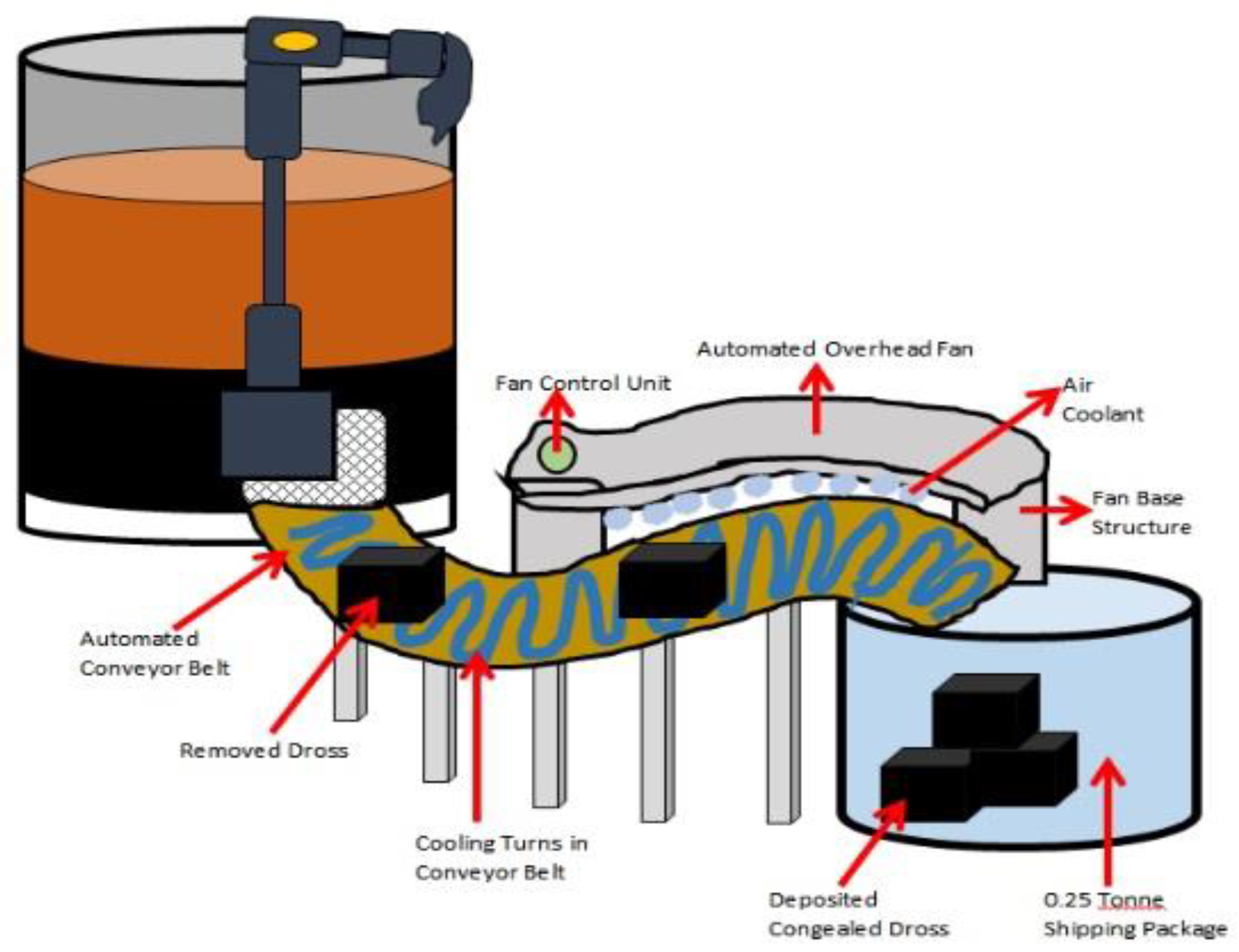
When the dross cube gets on the automated cooling conveyor belt, it automatically switches on due to detection by a weight sensor. The conveyor belt control unit sends an activation message to the inlet and outlet valves of the conveyor belt borehole with room temperature (23 °C) water, causing both valves to open and activating the automated pump to begin pumping the room temperature water from the borehole into the 30-inch diameter cooling turns arranged in cylindrical fashion within the conveyor belts to cool the dross cube down to 23 °C and solidify it. At the same time, the control unit of the conveyor belts sends an activation message to the automated overhead fan control unit causing it to switch on the fan to assist in solidifying the dross cube. The length of the conveyor belts is estimated to be 15 m and speeds of 0.05 m/s, 0.1 m/s and 0.15 m/s can be selected. Once the dross cube gets to the end of the conveyor belt, it is dropped into a 0.25 tonne shipment container that can then be sealed and sent off to final consumers and customers.

3. Results

A comparison of the spill volume percentage for crude constituent extraction using the extraction process currently used in the Oil and Gas industry today and that of the Automated Crude Constituent Extractor is shown in Table 2.
The time taken to extract the crude constituent from the refined crude oil suing the extraction process currently used in the Oil and Gas industry today is compared with the extraction time of the Automated Crude Constituent Extractor in Table 3.
The extraction output volume for each crude constituent using the extraction process currently used in the Oil and Gas industry today is compared with the extraction output volume for each crude constituent using the Automated Crude Constituent Extractor in Table 4.
The national revenue loss associated with crude oil volume loss and remediation costs to clean up the associated crude oil spills from the current extraction process in the Oil and Gas Industry and the automated crude Constituent Extractor is shown in Table 5.
Photographs of the working unit will be available after successful prototype development. Our companies are already in the process of receiving funding from the Nigerian Oil and Gas Industry and Government to develop the prototype.

4. Discussion

The major contribution of the Automated Crude Constituent Extractor to the Oil and Gas Industry is as follows:
  • Automatic determination of the desired constituent to be extracted from the refined crude transported to the extraction site, as well as the percentage of the refined crude to be used for the extraction of each of the desired crude oil Constituent.
  • Automatic partitioning and transportation of the incoming refined crude oil to the different sections of the extraction site for each constituent extraction.
  • Innovative Engineering design for crude oil constituent extraction process that reduces constituent extraction time from 10–32 h to 34–36 min.
  • Innovative Engineering design for the crude oil constituent extraction process that increases the volume of constituent extracted from the refined crude oil.
  • Innovative Engineering design for the crude oil constituent extraction process that ensures no refined crude oil or constituent is spilled throughout the entire process, resulting in financial savings, health care protection and prevention of environmental pollution.
  • Innovative Engineering design for the crude oil constituent extraction process that eliminates the need for back-breaking physical labor for many hours and prevents physical accidents (e.g., from heating of refined crude).
In the current refining and extraction sites today, the time taken to extract the components of the crude oil from the raw crude is counted in hours (see Table 3) and certainly should be shortened to improve the efficiency of the extraction process. If it takes hours to extract a single constituent from the raw crude, then it affects the amount of the constituent that is available for a nation at any given point in time. It takes 10–32 h to extract four components of refined crude (Petrol, Diesel, Dross-Diesel and Dross) in order for them to be made available to the country. At this point, modern technology needs to be involved in order to shorten the time taken for crude constituent extraction. The Automated Crude Constituent Extractor is capable of extracting each and every one of the constituents of the crude oil within 19–27 min, guarantees a more efficient and robust extraction process and a great boost in constituent output.
The extraction efficiency of the current extraction process needs to be improved. For every tonne of refined crude oil shipment brought to the extraction site, a maximum of 74% of its total volume can be extracted as Petrol Constituent, 68% as Diesel, 49% as Dross-Diesel and 50% as Dross and 58% as Kerosene. The remaining percentage is discarded as waste. Now, using the Automated Crude Constituent Extractor, patented, owned and developed by RACETT CANADA INC. and RACETT NIERIA LTD., Zone 8, FCT, Abuja, Nigeria, its innovative design allows for a maximum of 98% of the volume of the tonne of refined crude to be extracted as Petrol Constituent, increasing the overall efficiency of constituent extraction and minimizing waster percentage for every constituent. This is enough to guarantee that automating the extraction process of the crude constituent is a solid investment that will ensure substantial net-growth in any nation’s Gross Domestic Profit (GDP). The reduction in water percentage for reach constituent results in increased per-capital income for each person in the country.
For each of the crude constituent extracted, 16–25% of its total volume compared to the original is lost during the extraction process (see Table 2). As mentioned before and shown in Table 5, this loss equates to millions in revenue and remediation cost. In Canada 1% volume spill results in $820–$4250 CAD in revenue loss and costs $280,000–$650,000 CAD to clean up. In Nigeria, the 1% volume spill results in ₦120,000–₦1,285,000 in revenue loss and ₦67,000–₦1,870,000 in remediation cost [2]. Multiplying these values by the 16–25% total spill volume that happens for the extraction for each crude constituent gives you a true and shocking value of the generated revenue that is lost. By using the Automated Crude Constituent Extractor described in the Materials and Methods Section for extracting the constituents of refined crude, the loss stated above can be saved, as the Extractor has 0% total volume spill and absolutely no remediation cost.
The manual labor involved in the extraction process currently used in the industry today warrants the urgent introduction of automated and user-friendly technology to assist the extraction workers in carrying out their responsibility with ease, advanced skill and dignity.
The extraction of each constituent from the refined crude takes several hours and is physically taxing on the strength and health of the workers (see Figure 1). The annual fire used for extraction of the petrol, diesel, dross-diesel, dross and kerosene is not only labor intensive but also hazardous. The daily or weekly accidental burns associated with the current method can be avoided by the sophisticated heating method employed in the Extraction Receptacles of the Automated Crude Constituent Extractor. The physical exertion required to shift the cooking barrel after extraction is also eliminated as the cooling of the extracted constituent is performed within the extraction receptacle within minutes. For the transferring of the extracted dross to tits shipment packages, the workers have to pack it out from the cooled cooking barrel with their bare hands for 14 long hours. The need for automating this process is unquestionable and has been exceptionally addressed by the Automated Crude Constituent Extractor. The manual transfer using kegs for each crude constituent extraction process has also been eliminated by this system.
When the refined crude gets to the extraction site, the extractors are made aware of the crude constituent required by the customer for that particular shipment. They then have to manually unload the refined crude and physically carry them to the section of the extraction site for the requested constituent. If the customer or company has requested more than one crude constituent, then the workers have to manually separate the total volume of the refined crude oil shipment into partial volumes specified by the customer for each of the desired constituent before carrying the partial volumes to their corresponding extraction site sections. The time taken to carry out this initial process was not even added to the extraction time stated in Table 3. With the Automated Crude Constituent Extractor, the percent of the total volume of refined crude shipment to be used for the extraction of each constituent is sent to the extraction site via automated text, e-mails and start transfer alert message before the shipment is sent to the extraction site. Once the shipment gets into the extraction site, the total volume of the refined crude shipment is automatically pumped in and partitioned for each of the user-requested constituent based on the specified constituent percentage (see Figure 4). Once a sub-volume has been successfully partitioned, it is sent directly to the Extraction Receptacle for its crude constituent and the extraction begins immediately. This technologically advanced partitioning and process has never before been done in any industry and is essential for the swift movement of the refined crude into the extraction site.
The separation of the Dross-Diesel from the Dross after the Dross-Diesel Extraction process takes sixteen hours, two hours to manually scoop out the Dross-Diesel liquid sitting on top of the dross using kegs into the Dross-Diesel Shipment Packages and twelve hours to transfer the residual dross at the bottom of the cooled cooking barrel to its shipment package using bare hands. This process is swift and completely automated using our Automated Crude Constituent Extractor.
Dross-Diesel Separation is carried out in the Dross-Diesel Separator. After waiting a little, his topmost Dross-Diesel valve is automatically opened so that the Dross-Diesel can flow out of the Separator and into the Dross-Diesel Receptacle for final shipment to his consumers and customers. As it flows through the dross-diesel pipe, the dross-diesel passes through the pipeline refining filter that ensures complete separation of the dross-diesel from the residual dross (see Figure 7). The pipeline refining filter has a thick mesh that is weighted for the dross particles to ensure that no particle is found in the final dross-diesel shipment. It also has a strong structure ring for frim attachment to the walls of the pipeline using holding pins. The Dross-Diesel valves for each of the three dross-diesel pipes are opened in sequence one after the other to completely transfer the dross-diesel from the dross-diesel separator to the dross-diesel receptacle for final shipment. Control for the dross-diesel valves is done using the Dross-Diesel valve control units (see Figure 7). This level of automated Separation is not yet established in the Oil and Gas Industry and is not only efficient but also time saving.
As mentioned before, the removal of the dross from the dross-diesel needs to be improved. The automated process for dross removal is shown in Figure 4. Not only does it automatically removed the dross form the dross-diesel separator, it also shapes the dross, using the dross spade remover and spinning of the separator, at 2000 4000, or 6000 rpm (Figure 4a), so that it is portable and easily carried. The cooling conveyor belt is an innovative method of reducing temperature in substances. Essentially 16-inch diameter cooling turns arranged in cylindrical fashion are installed within the conveyor belt and near its surface. Room Temperature (23°) water is automatically run through the cooling turns as soon as the conveyor is automatically switched on by detecting the weight of the exited dross in the shape of a cube suing weight sensors embedded in the conveyor belts (see Figure 4). A distance of 15 m at speeds of 0.05, 0.1 and 0.15 m/s ensure the dross cube is congealed and cooled down to a solid cube. An automated overhead fan is also used to assist in cooling the cube while it is on the conveyor belt. At the end of the belt, the dross cube falls into the dross shipment package with a maximum capacity of 0.25 tonnes, as this is the maximum capacity of dross that can be extracted from 12 tonnes of refined crude. Once the dross for a shipment has been completely deposited in the shipment package, it is sealed up and ready for shipment. The Dross Extraction, Removal, Shaping, Congealing and Deposition into the Dross Shipment Package is exceptional and warrants further investigation for this and many other applications. Because the extraction process is fully automated, there is no backlog in requests for extraction from refined crude oil shipments, as is the case with the current extraction process. Instead of 10–32 h to extract constituents from 2 tonnes of refined crude, the Automated Crude Constituent Extractor completes the process for 1 tonne of refined crude in 17–23 min or 2 tonnes of refined crude in 34–46 min. In 10–32 h, the Automated Crude Constituent Extractor can complete the extraction process for 35.3–116.5 tonnes of refined crude oil. This is an extraction capacity output gain of 1765–5825% and the heath of the extraction workers are not compromised [3,4,5,6,7].
In Nigeria, there are few (insufficient) refineries that are manually driven. Refineries in Nigeria simply refine the crude oil but do not break it down into its several components. This is a major source of concern as each nation that produces oil should be responsible for refining and producing the components or constituents of crude oil. The Automated Crude Constituent Extractor takes care of this shortage and is strongly recommended when Nigeria increases the number of its functioning refineries. The available refineries in Nigeria are insufficient to adequately and fully extract the number of constituent components from refined crude for the entire nation and even for small regions within the nation. They can only extract one or two constituents from the refined crude and not the full range. Regions in Nigeria in which the refineries are located do not want environmental pollution and the health implications associated with refining. This is absent from the Automated Crude Constituent Extractor. Shipment from extraction site to resource consumers is manually driven via tankers. With the Automated Crude Constituent Extractor, transportation to designated source facilities is achieved through constituent pipelines and automated crude transporters. If Nigeria wants to increase its refining capacity, it is far better to invest in the Automated Crude Constituent Extractor and avoid national backbreaking physical endurance and labor, prevent environmental pollution in a nation already plagued by crude oil spills, bolster national revenue by improved refining output capacity and lack of crude oil or constituent spill by the system and generate quality employment in the country for the Oil and Gas Industry. The Automated Crude Constituent Extractor ensures that any Oil producing country can conduct the refining of their own crude oil internally, can do so automatically and for any quantity of crude oil they extract and refine from their reserves. This gives them a higher ranking and standing in the international arena.
The Automated Crude Constituent Extractor needs to be implemented swiftly in the Oil and Gas Industry today so that oil-producing nations can start enjoying these benefits.

5. Conclusions

The current extraction process in the Oil and Gas Industry today takes 10–32 h for 2 tonnes of refined crude, incurs 16–25% of the total volume spill, has an extraction efficiency of 50–74%, experiences $820–$4250 CAD of revenue loss for every 1% spilled and costs $280,000–$650,000 CAD to clean up a single percent. The Automated Crude Constituent Extractor extracts constituents from 2 tonnes of refined crude in 34–46 min, incurs no volume spill, has an extraction efficiency of 76–98%, results in no revenue loss and no remediation cost. This system needs to be implemented immediately in the Oil and Gas Industry today so that oil producing nations can start enjoying these benefits.

Author Contributions

G.R.: Design and Development of the Pipeline Refining Filter and Dross-Diesel Separator. W.O.: Design and Development of the Submersible and Air Volume Receptacle Estimators and the Extraction Control Unit. E.E.: Design and Development of the Automated Refiner and Dross Removal. O.E.: Design and Development of the Extraction Control Unit, Extraction Receptacles, Automated Crude Transporters, Dross-Diesel Separator, and Dross Removal. G.O.: Design and Development of the Extraction Control Unit, Extraction Receptacles, Automated Crude Transporters, Dross-Diesel Separator, and Dross Removal. E.E.T.: Design and Development of the Extraction Control Unit, Extraction Receptacles, Automated Crude Transporters, Dross-Diesel Separator, and Dross Removal.

Funding

This work was fully funded by RACETT CANADA INC, New Brunswick, Canada, and RACETT NIGERIA LTD., Zone 8, FCT, Abuja, Nigeria.

Conflicts of Interest

The authors declare no conflict of interest.

References

  1. Data obtained from Key Individuals in the Oil and Gas Industry in Canada via oral reports, March 2018.
  2. Data obtained from Key Individuals in the Oil and Gas Industry in Nigeria via oral reports, March 2018.
  3. Chang, S.E.; Stone, J.; Demes, K.; Piscitelli, M. Consequences of oil spills: A review and framework for informing planning. Ecol. Soc. 2014, 19, 26. [Google Scholar] [CrossRef]
  4. Inoni, O.; Douglason, E.; Omotor, G.; Adun, F.N. The Effect of Oil Spillage on Crop Yield and Farm Income in Delta State, Nigeria. J. Cent. Eur. Agric. 2006, 7, 41–48. [Google Scholar]
  5. D’Andrea, M.A.; Kesava Reddy, G. Health Consequences among Subjects Involved in Gulf Oil Spill Clean-up Activities. Am. J. Med. 2013, 126, 966–974. [Google Scholar] [CrossRef] [PubMed]
  6. Oyebamiji, M.A.; Mba, C.I. Effects of Oil Spillage on Community Development in the Niger Delta Region: Implications for the Eradication of Poverty and Hunger (Millennium Development Goal One) in Nigeria. World J. Soc. Sci. 2014, 1, 27–36. [Google Scholar]
  7. Okoye, C.O.; Okunrobo, L.A. Impact of Oil Spill on Land and Water and its Health Implications in Odugboro Community, Sagamu, Ogun State, Nigeria. World J. Environ. Sci. Eng. 2014, 1, 1–21. [Google Scholar]
  8. Zaki, M.S.; Authman, M.M.N.; Ata, N.S. Effects of Environmental Oil Spills on Commercial Fish and Shellfish in Suez Canal and Suez Gulf Regions. Life Sci. J. 2014, 11, 269–274. [Google Scholar]
  9. O’tega, A.E.; Ofualagba, G. Development of an Aerial Robotic Oil Spill Surveillance (AROSS) System for Constant Surveillance and Detection of Spills from Crude Oil Pipelines. Int. J. Unmanned Syst. Eng. (IJUSEng) 2016, 4, 19–33. [Google Scholar] [CrossRef]
  10. O’tega, A.E.; Ofualagba, G. Exploring the Feasibility of Robotic Pipeline Surveillance for Detecting Crude Oil Spills in the Niger Delta. Int. J. Unmanned Syst. Eng. (IJUSEng) 2017, 5, 38–52. [Google Scholar] [CrossRef]
  11. O’tega, A.E.; Ofualagba, G. Design of an Underwater Robotic Oil Spill Surveillance (UROSS) System for Spill Surveillance and Detection from Subsea Crude Oil Pipelines. Int. J. Unmanned Syst. Eng. (IJUSEng) 2018. submitted. [Google Scholar]
Figure 1. Current Extraction Process for Crude Oil Constituents in the Refining Industry Today.
Designs 02 00022 g001
Figure 2. Automated Crude Constituent Extractor.
Designs 02 00022 g002
Figure 3. Full Figure of Automated Refinery.
Designs 02 00022 g003
Figure 4. Automatic Partitioning of Refined Crude Entering Refinery (a) Customer—requested volume of refined crude automatically being diverted to Diesel Extracting Receptacle (b) Customer-requested volume of refined crude automatically being diverted into Dross Receptacle.
Designs 02 00022 g004
Figure 5. Refining Pipeline Filter.
Designs 02 00022 g005
Figure 6. Dross Spade Remover.
Designs 02 00022 g006
Figure 7. Separation of Dross-Diesel from Dross Using the Diesel-Dross Separator.
Designs 02 00022 g007
Table 1. Percent Volume loss in Transfer Process during Extraction of Crude Constituents.
No.Crude ConstituentSite Arrival to Cooking BarrelCooking Barrel to Other ContainerOther Container to Refined RateCooking Barrel to Shipment Container
1Petrol7126-
2Diesel11--6
3Dross-Diesel6--10
4Dross6--13
Table 2. Spill Volume Percentage for Current Extraction Process and for the Automated Crude Constituent Extractor.
No.Crude ConstituentSpill Volume % for Current Extraction ProcessSpill Volume % for Automated Crude Constituent Extractor
1Petrol250
2Diesel170
3Dross-Diesel160
4Dross190
Table 3. Extraction Time for current Extraction process and for the Automated Crude Constituent Extractor for 1 Tonne of Refined Crude.
No.Crude ConstituentExtraction Time for Current Extraction ProcessExtraction Time for Automated Crude Constituent Extractor
1Petrol10 h22 min
2Diesel12 h19 min
3Dross-Diesel12 h27 min
4Dross32 h23 min
Table 4. Extraction Output Volume for Each Crude Constituent Using the Current Extraction Process and the Automated Crude Constituent Extractor for 1 Tonne of Refined Crude.
No.Crude Constituent% Volume of Refined Crude as Extraction Output for Current Process% Volume of Refined Crude as Extraction Output for Automated Crude Constituent Extractor
1Petrol7498
2Diesel6897
3Dross-Diesel4998
4Dross5098
5Kerosene5876
Table 5. National revenue loss and Remediation Loss for Spills using the Extraction Process currently in the Oil and Gas Industry.
CanadaNigeria
No.Crude ConstituentRevenue Loss from 1% Volume SpillRemediation Cost to Clean up 1% Volume SpillRevenue Loss from 1% Volume SpillRemediation Cost to Clean up 1% Volume Spill
1Petrol$4250 CAD$650,000 CAD₦1,285,000₦1,870,000
2Diesel$3275 CAD$450,000 CAD₦975,000₦1,540,000
3Dross-Diesel$2960 CAD$400,000 CAD₦825,000₦764,000
4Dross$820 CAD$280,000 CAD₦650,000₦720,000
5Kerosene--₦120,000₦67,000

