Article

CFD Evaluation on the Pre- and Post- Renovation, and Windows and Doors Opening, of a Typical, Walled, Detached Family House in the Philippines

by
Napoleon A. Enteria
1,2,3,* and
Odinah L. Cuartero-Enteria
4
1
Building Research Institute, Tsukuba 305-0802, Japan
2
Graduate School of Engineering, Tohoku University, Sendai 980-8579, Japan
3
Enteria Grün Energietechnik, Davao 8000, Philippines
4
Surigao Del Sur State University at Cantilan, Cantilan 8317, Philippines
*
Author to whom correspondence should be addressed.
Infrastructures 2017, 2(4), 16; https://doi.org/10.3390/infrastructures2040016
Submission received: 18 June 2017 / Revised: 16 October 2017 / Accepted: 16 October 2017 / Published: 22 October 2017

Abstract

:
Natural ventilation is an important consideration to minimize the usage of mechanical ventilation and air-conditioning systems in the design, use, and renovation of residential houses and buildings. In this study, a computational fluid dynamics (CFD) is used to evaluate the wind field around and inside the walled, detached family house after a series of house renovations, with the effect of window and door openings. The effect of the lot perimeter wall is investigated as to how it affects the wind field around and inside the house. The results show that the height of the lot perimeter wall affects the wind field around and inside the house. They show that the opening of the doors and windows significantly affects the wind field around and inside the house. The construction of the firewall at the back of the house affects the wind field. Based on the results, the design of the house with the consideration of wind direction, neighborhood, and how the occupant uses the house have a great impact on the optimum utilization of the prevailing wind for natural ventilation, as they affect the wind field around and inside the house.

Graphical Abstract

1. Introduction

The Philippine weather and climatic conditions are affected mainly by its surrounding bodies of water, as it is an island nation [1]. As the country is situated in the typhoon belt region of the Eastern Asia Pacific, the country has an average of 20 tropical cyclones per year, which result in loss of lives and destruction of property. The outdoor temperature of the country is hot and humid, typical of the tropical climate. The outdoor temperature and humidity are high, which results in a need for ventilation and air-conditioning, both natural and artificial, to maintain thermal comfort [2].
The residential building sector is one of the main consumers of electricity in the Philippines [1]. Space cooling and air-conditioning systems are the second largest consumers of household electricity after refrigeration [2]. In the Philippines, most of the houses of middle to upper class families are made of concrete with corrugated sheet steel roofing. Normally, houses in the Philippines are not insulated, as is typical in tropical houses; thus, the indoor thermal environment is affected by the changing outdoor weather conditions [2]. Most family houses of middle to upper class families utilize an air-conditioning system to maintain indoor thermal comfort. Natural ventilation is normally not taken into consideration in the design of the Philippine residential houses and buildings as there are no set standards for the use of natural ventilation.
Many studies show that the planning and design of residential buildings and houses are major factors when considering the application of natural ventilation [3,4,5,6,7,8,9,10]. In Singapore, the Building and Construction Authority recommended that the design of residential buildings take natural ventilation into consideration [11]. Other tropical countries of Southeast Asia are exploring the design of residential buildings and houses with the evaluation of the use of prevailing wind in their ventilation [6,7]. Hence, it is very important to design residential buildings and houses, taking into consideration the prevailing wind direction and the neighborhood [11,12]. In hot and humid tropical climates, some studies and regulations are considering the usage of natural ventilation to minimize energy consumption [12,13,14,15,16]. In the Philippines, the detailed design and analysis of residential buildings and houses, taking into consideration natural ventilation, is not currently considered due to shortcomings in regulations and understanding in the field [2,17].
In the hot and humid Philippine tropical climate with expensive electricity, utilization of natural ventilation is very important to minimize the use of mechanical ventilation and air-conditioning [1,18]. This paper presents the first application of the computational fluid dynamics (CFD) in the analysis and evaluation of the wind field around and inside the walled, detached family house in the Philippines, to visualize and understand the effect of the parameters affecting the wind field around and inside the house using the developed and validated model presented in our previous paper [17]. Our previous paper shows the developed CFD model that was validated based on the data from full scale and wind tunnel results. Many studies show the importance of using CFD analysis in the visualization of flow in houses and buildings. Figure 1 and Figure 2 show the diagram of the walled, detached family house in which the evaluation of the wind field is implemented. The objective of the study is to determine how the series of the house renovation, the window and door openings, and the house lot perimeter wall affect the wind field that results in the non-utilization of prevailing wind for natural ventilation. It is expected that with this study, motivation for the utilization of natural ventilation in the design and usage in residential houses and buildings will increase.

2. Methodology

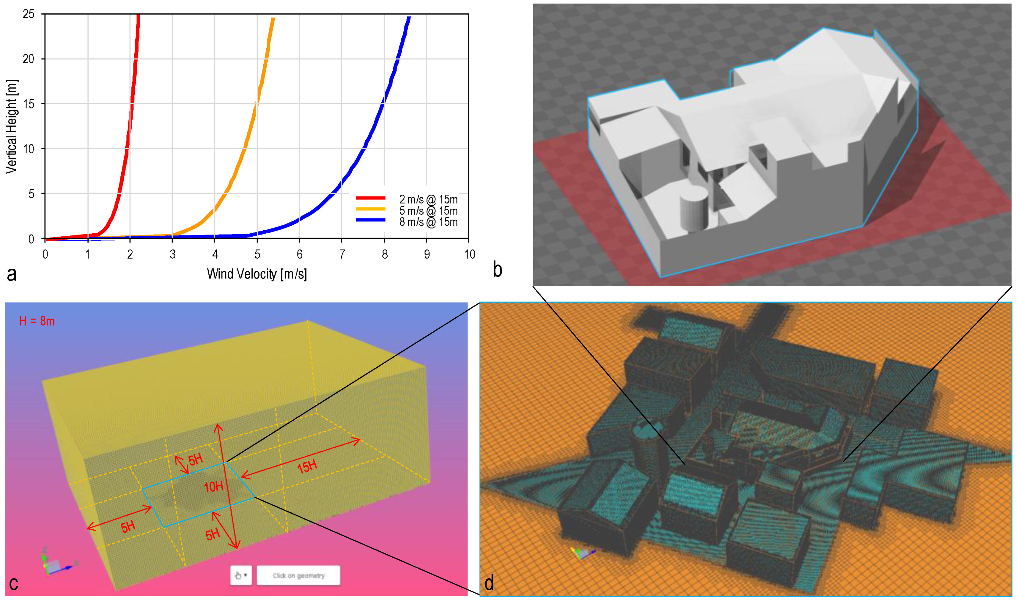
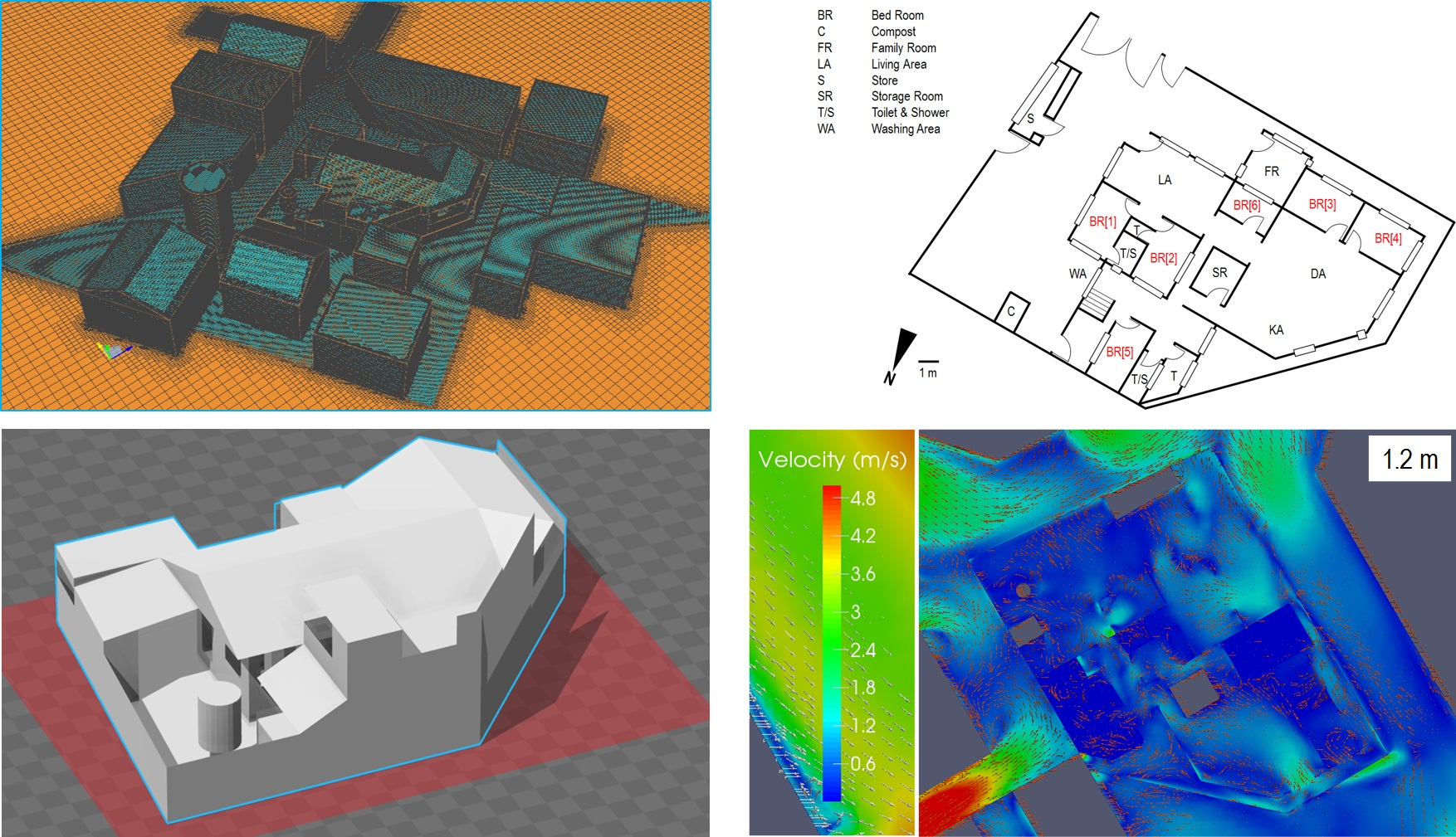
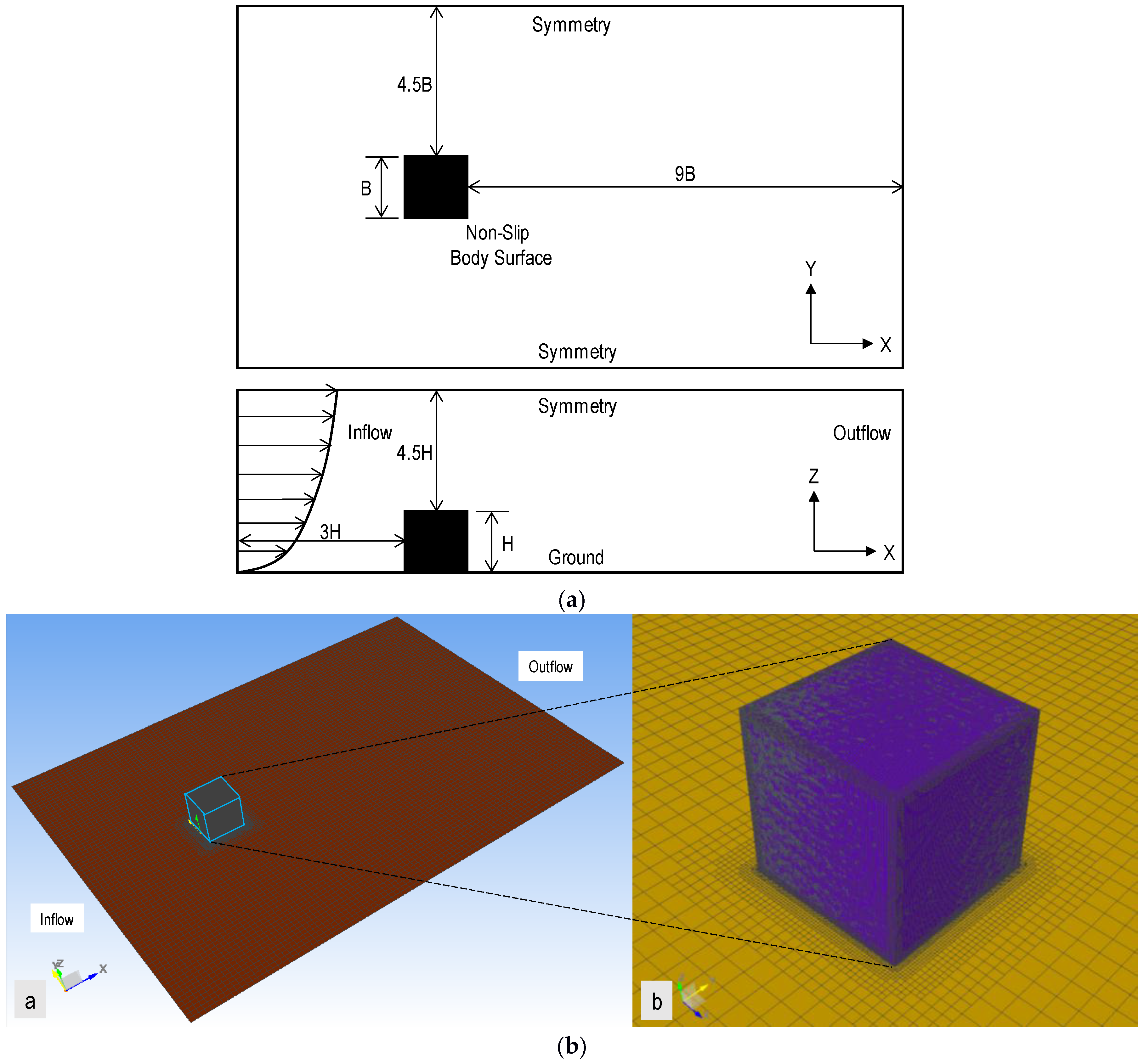
2.1. Computational Fluid Dynamics

The computational tool called computational fluid dynamics (CFD) is a powerful tool to solve and visualize the air flow around the buildings and houses using the visualizing software. The CFD is based on the Navier-Stokes equations. In this research, the compressible steady-state Reynolds-Averaged Navier Stokes (RANS) equations were solved using the finite volume method-based OpenFoam solver [19] incorporated in simFlow software [20]. The OpenFoam computational fluid dynamics solver has been used and validated by many researchers [17]. Based on several studies, the solver can replicate the results from different major computational fluid dynamic softwares [21]. The solver was also validated by different experimental results [22]. Hence, in this study, the above solver is utilized in solving the problem of the walled, detached family house.

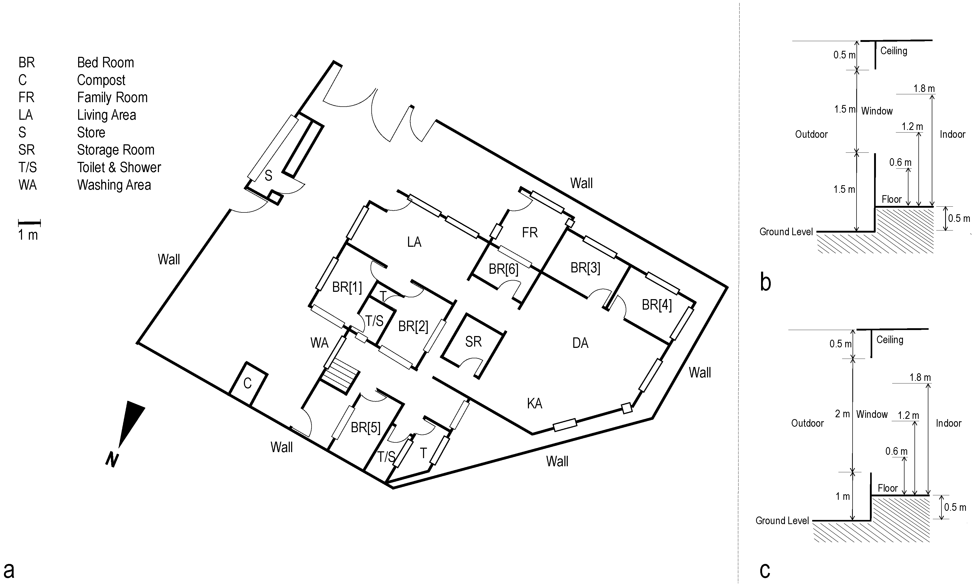
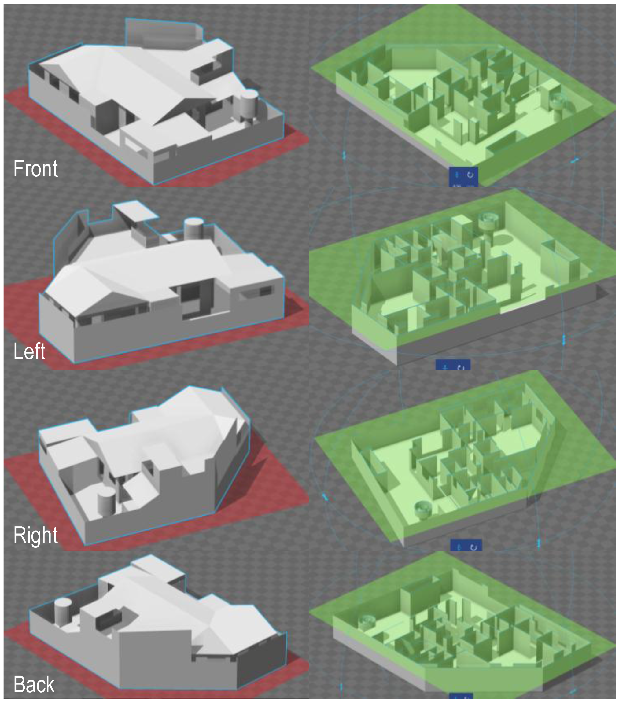
2.2. Numerical Modelling

Figure 3 shows the computational model preparation utilized in this study. It shows the computational domain, boundary conditions, and computational grid generated using the very fine and unstructured mesh with five layers [17]. The modeling and configuration of the computational domain for the present study is shown in Figure 4. The domain configuration is based on the recommended dimensions in order to not affect the wind field around the neighborhood under consideration [23]. The H is based on the height of the tallest part of the neighborhood. In this case, the H is 8 m, which is the approximate height of the mango tree shown in the domain (Figure 4d). Previous studies show that it is very important to do parametric studies of the computational grid [24,25,26]. Hence, this study conducted several parametric studies before deciding to use the computational grid as we did in our previous studies [17]. Figure 4a shows the wind velocity at different heights. There are three cases of wind velocity based on 15 m height, which are 2 m/s, 5 m/s, and 8 m/s for representation purposes. The consideration of 15 m height of wind velocity is based on the Building and Construction Authority (BCA) of Singapore’s recommendation for wind velocity height, as there is no recommendation in the Philippines for computational fluid dynamic (CFD) evaluation [11]. The selection of 5 m/s is based on the average wind speed in Davao City, Philippines [27]. Based on the weather pattern in the area, a large portion of the wind speed is from the north and east (32%), particularly during the summer months when wind directions are at 57% (from the north and east). In the simulation cases, one direction of wind is selected, which is 20° north of east based on the observations gathered in the locality. The typical wind speed in the city is from 0 m/s to 5 m/s, with a maximum daily average value of 5 m/s. The maximum temperature is from the end of March to the beginning of May, the summer season, with an average high temperature of 33 °C. In the March to May period, the average low temperature is 25 °C. Figure 4b shows the walled, detached family house presented in this study. The modeled house with the neighborhood is in the computational domain, as shown in Figure 4c. Figure 4d shows the mesh of the modeled house with the neighborhood in the computational domain. The mesh for the computational grid is 200 × 200 × 100 in the x, y, and z directions for this study, with 9,872,158 cells and 10,938,893 nodes. The time step used in the simulation is 0.5 s, with a 55 s maximum simulation time, as is determined to be enough in the converging of the simulation. A very fine and unstructured mesh is used in the study, as presented in Figure 4d. The very fine and unstructured mesh with five layers around the walled, detached family house with the neighborhood was selected as well to make sure that in the wall with the opening, the opening is fully defined.
In this modeling and simulation, the value of the velocity profile constant (α) is 0.15. At the 0.15 value, the inlet velocity profile follows the velocity profile, as shown by Enteria [17] and Irtaza et al. [28], as presented using Equation (1). The result of Equation (1) is shown in Figure 4a. The value of the turbulence model constant (Cu) is 0.09. The von Karman constant (K) is 0.41. The presented turbulence model constant and von Karman constant are the typical values in modeling. The friction velocity ( u x ) is calculated based on Equation (2). The aerodynamic roughness length ( z o ) in Equation (2) is determined according to the relationship between roughness height ( k s ), constant ( C s ) and aerodynamic roughness length ( z o ), shown by Abohela et al. [29] based on the study of Blocken et al. [30]. Roughness height ( k s ) has a value of 0.12 based on our previous study [17].
Velocity profile:
U ( Z ) = U ( z H ) α
Friction velocity:
u x = kU log ( H z o ) ;   k s = 9.793 z o C s
k-profile:
k = u x 2 c u
ω-profile:
ω = k 1 / 2 c u 1 / 4 l ; l = 4 ( c u k ) 1 / 2
The k-ω SST turbulence model is used in the simulation. Based on the previous study, the k-ω SST turbulence model is in good agreement with the results of the wind tunnel and field measurement [17].

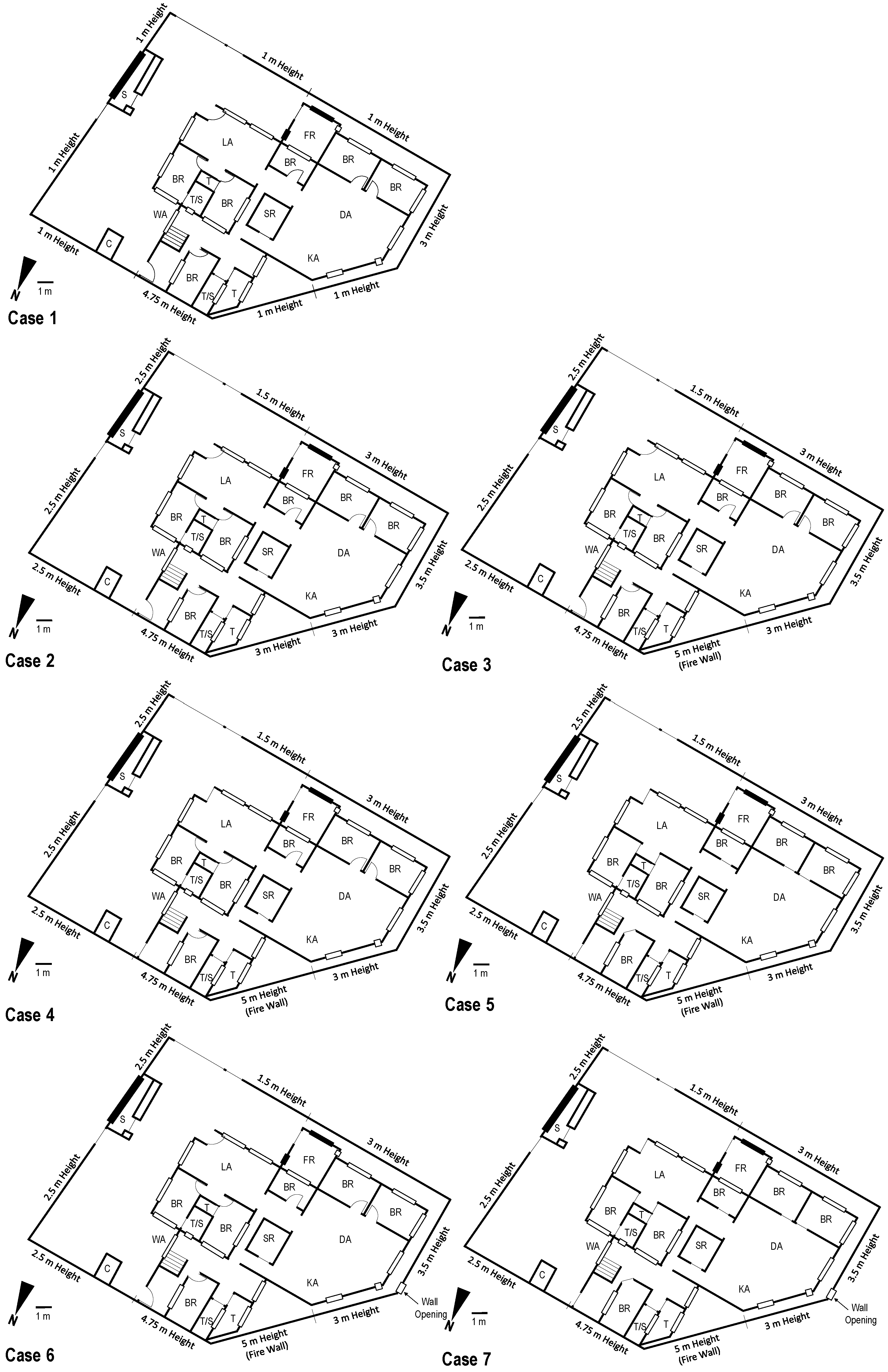
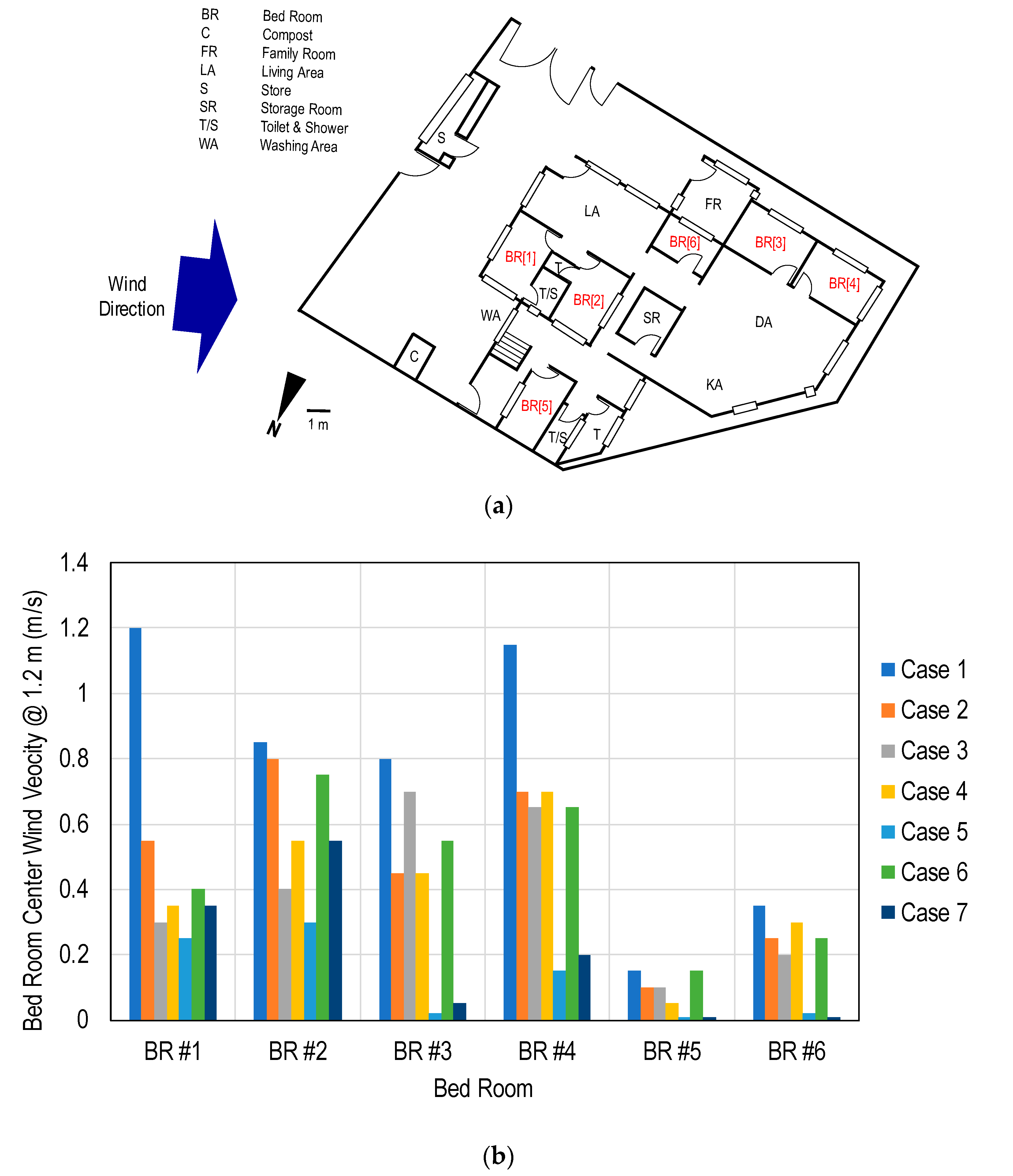
2.3. Simulation Cases

Figure 5 shows the simulation cases used in the evaluation of the walled, detached family house before and after renovation; the door and window openings and the opening of the lot perimeter wall at the left are presented as a possible solution to increase the wind inside the house. There are seven cases in the evaluation of the walled, detached family house relating to the pre-renovation and post-renovation of the house, which increase the lot perimeter wall height from 1 m to 2.5 m, as shown in Case 1 to Case 2. Both cases have opened doors and windows as a normal case during daytime. Case 3 shows when there is firewall at the back of the house. The lot perimeter wall height is increased to 5 m from 3 m (up to the height of the house roof) to protect the possible fire coming from the neighborhood from spreading. In the case, the doors and windows are all opened, except the windows for the store and of the family room, as it is always closed. Case 4 shows the case when the main (front and back) doors are closed and both indoor doors (bedrooms) and windows are opened. This case is possible during nighttime (sleeping time). Case 5 is for the case in which all doors are closed, both main doors and bedrooms door. Normally, bedroom doors are closed but sometimes all can be opened to increase the wind flow. Case 6 for is when the lot perimeter wall at the left has an opening to increase the wind flow going inside the house. It also shows the case in which all doors and windows are open except for windows in the store and family room. Case 7 shows when all the doors are closed and windows open, as shown in Figure 5, Case 7. Table 1 shows the summary of the computational test cases, as shown in Figure 5.

3. Results and Discussion

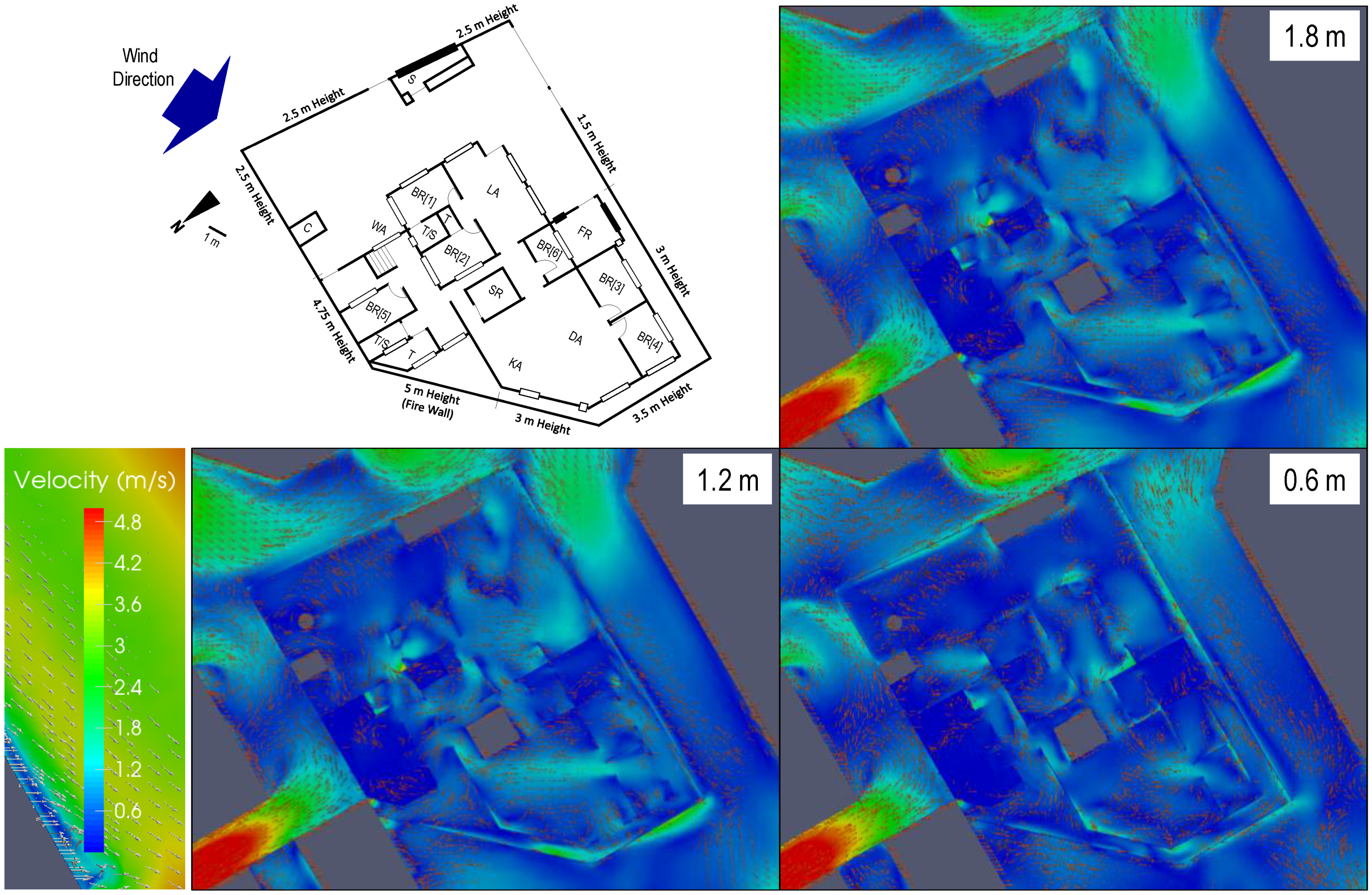
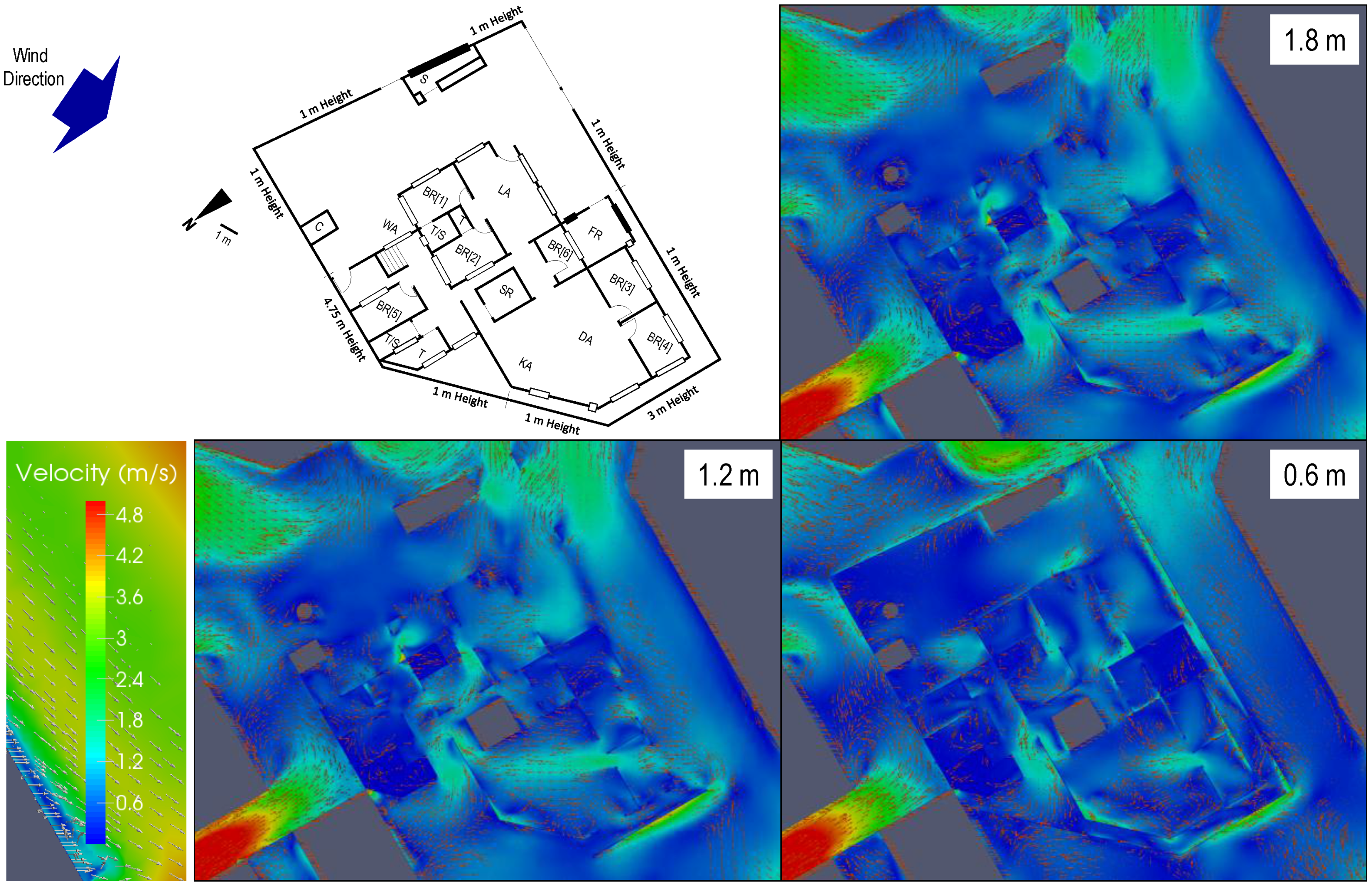
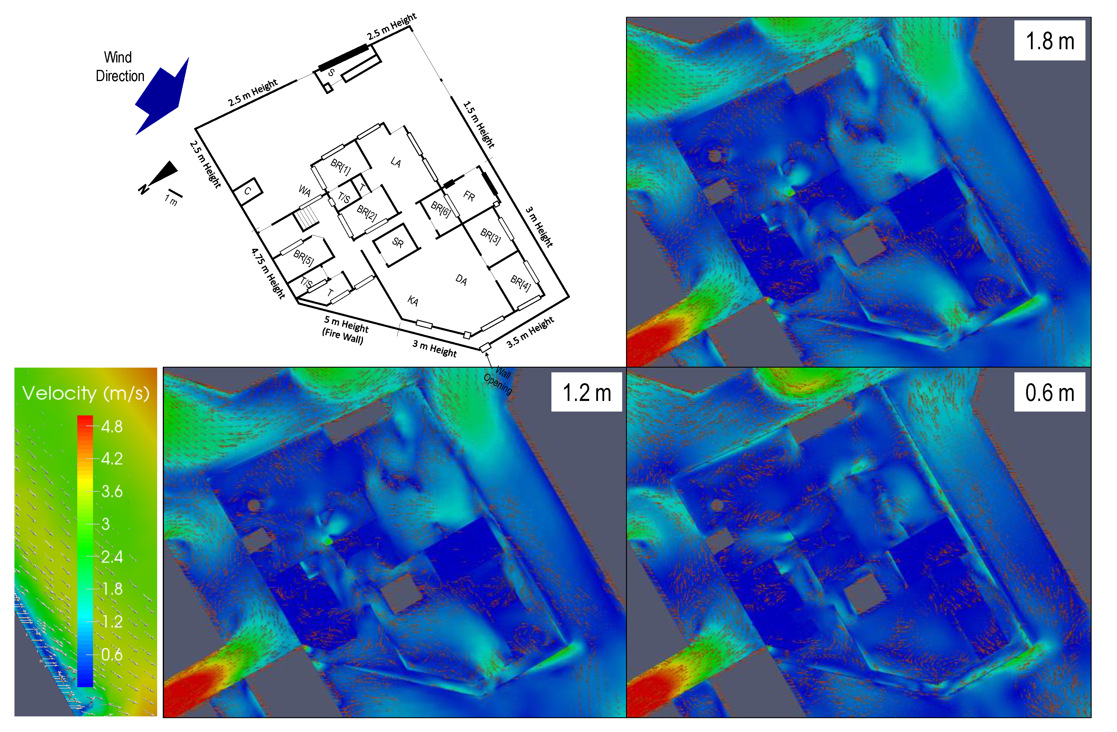
3.1. Effect of House Perimeter Wall

Figure 6 shows the case when most of the lot perimeter wall of the house is at 1 m above the ground, which is the original lot perimeter wall height (pre-renovation). The wall was erected using hollow block with iron bar and cement. The 3 m height lot perimeter wall at the left is an old concrete wall as shown in the Figure (pre-renovation). As shown in the results of wind velocity around and inside the house, high wind velocity occurred in the narrow spaces outside of the house wall due to the venturi effect (passage contraction). Inside the house, high wind velocity occurred in the narrow opening and passages, such as doors and windows. It shows that the living area (LA) is well ventilated followed by the dining area (DA) and kitchen area (KA), as these are big spaces with more windows and no obstruction. It also shows that bedroom 4 has good ventilation compared to other bedrooms as it has more windows, which results in the wind coming from the left passing through these windows and entering the house. The results show that bedroom 5 has less ventilation even when the door and windows are opened due to its location, which is in a secluded area of the house. It shows that bedroom 2 has good ventilation when door and windows are opened as cross air flow passes between windows and to the bedroom door. The result shows that wind in the dining area (DA) and kitchen area (KA) comes from the bedrooms as the wind from the left side of the house, going inside the house through the windows.
Figure 7 shows the result for Case 2 in which the lot perimeter wall height is increased from 1 m to 3 m based from Case 1 after the renovation. As presented, the wind inside the house decreases upon the increase of the lot perimeter wall height. As shown in the results, the living area (LA), dining area (DA), and kitchen area (KA) are still the most ventilated areas of the house due to the large area with no wind obstruction compared to the bedrooms. In the case for bedrooms, it shows that bedrooms 1 and 2 have good ventilation, followed by bedroom 4. Due to the increase of the lot perimeter wall height, the wind from the left side of the house (road area) passing bedrooms 3 and 4 is reduced due to the lot perimeter wall height serving as a barrier. It also shows that the increase of the lot perimeter wall height at the left of the house near the kitchen (KA) and toilet (T) serves as a barrier for the air to exit in this location compared to the lower lot perimeter wall shown in Case 1 (Figure 6). Hence, the increase of the lot perimeter wall height reduces the wind inside the house and affects natural ventilation.

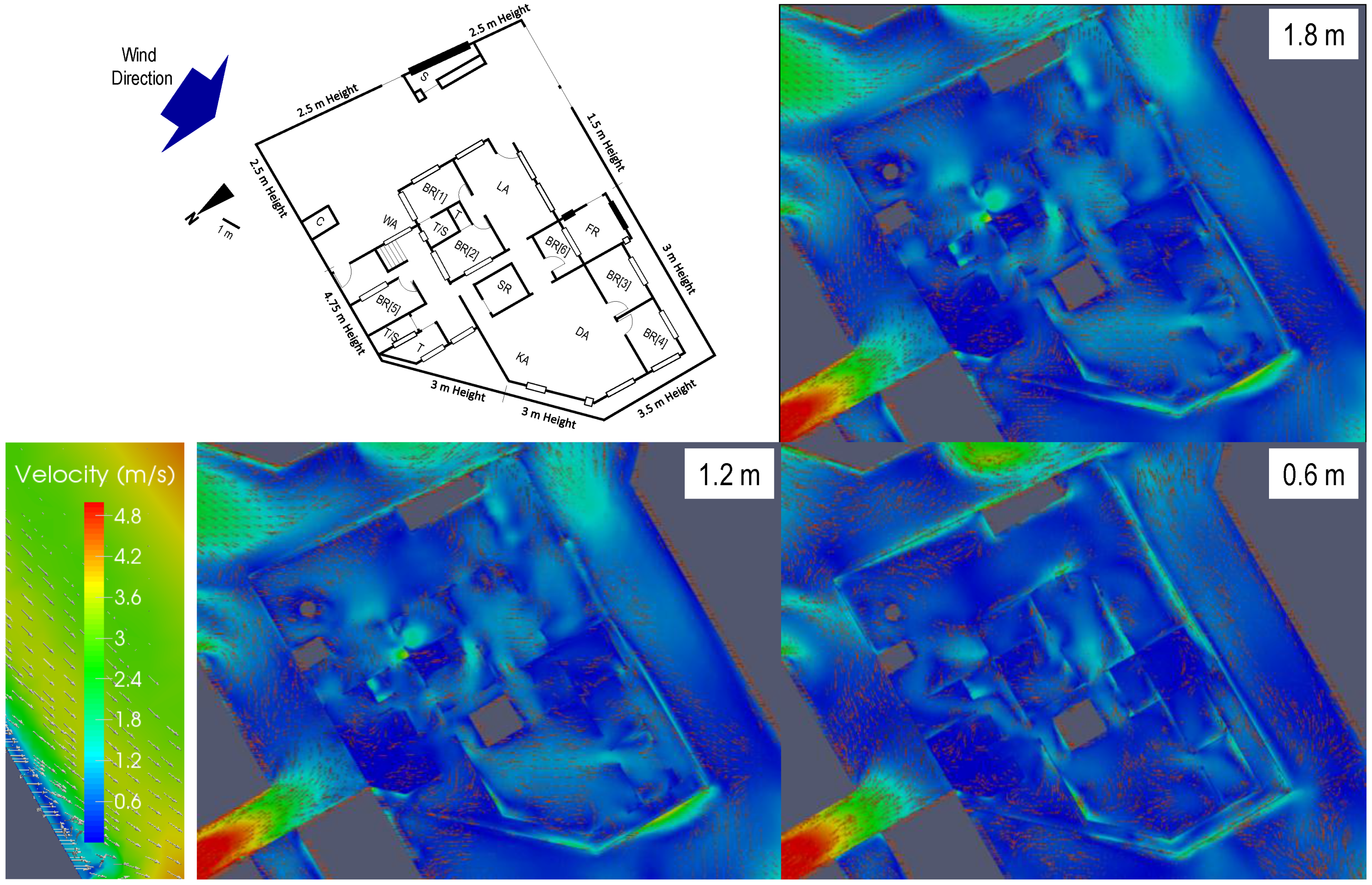
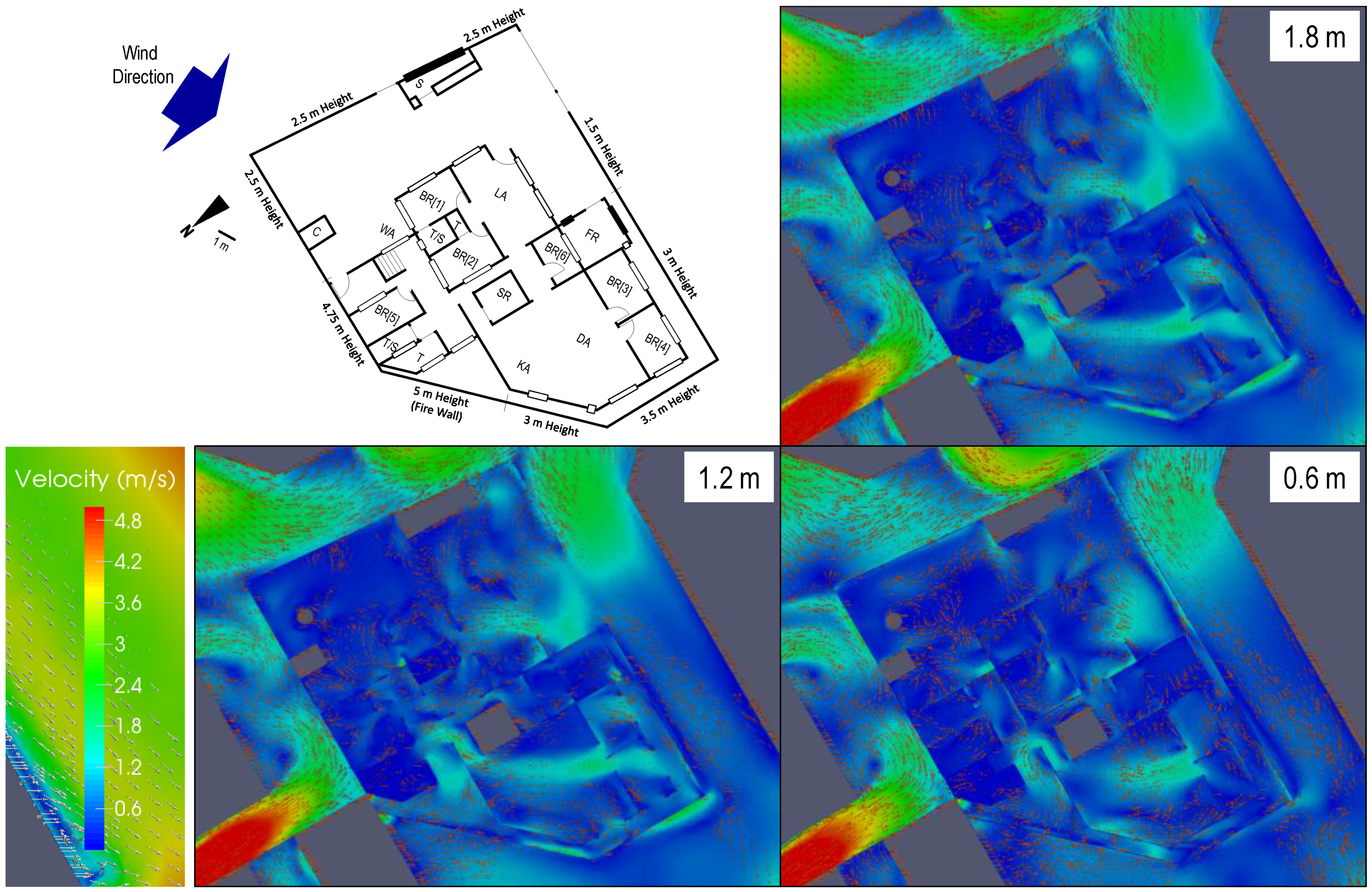
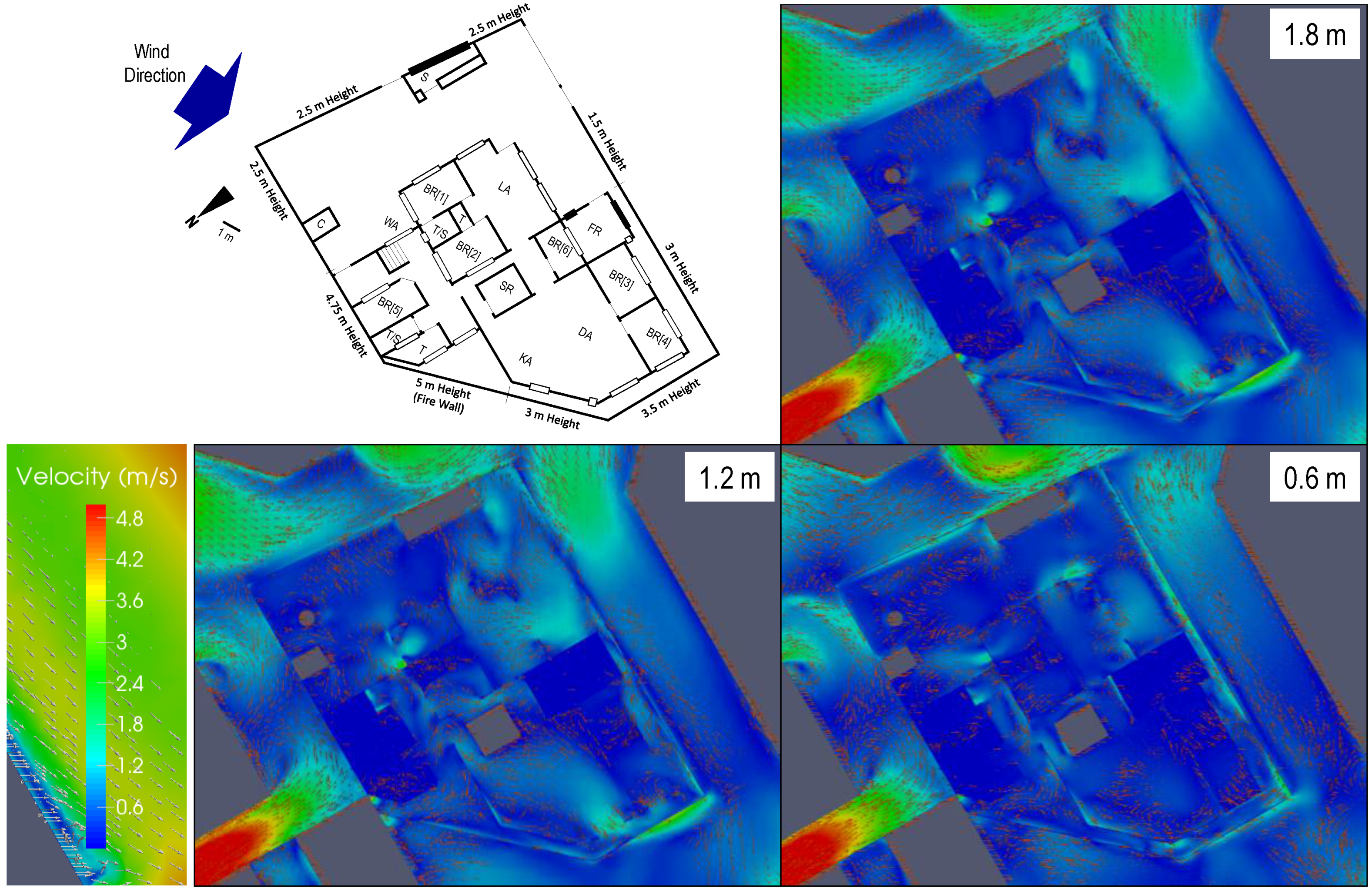
3.2. Effect of Constructed Firewall, Window, and Door Openings

Figure 8 shows the results for the case in which the firewall is constructed with open doors and windows. Comparing the results of Case 2 with no firewall and with open doors and windows to Case 3, it is shown that the wind inside the house is reduced, particularly in bedrooms 1 and 2. The wind in bedrooms 3 and 4 increases, as shown in the results, as the wind from the left passes into bedrooms 3 and 4. The wind in bedroom 5 is almost the same. The wind in bedroom 6 has a minimal increase due to the wind coming from the family room (FR), which passes through its window. The wind in the living area (LA) is concentrated in a particular area when compared to no firewall, in which it is more evenly distributed. It also shows that the wind in the dining area (DA) and kitchen area (KA) is still present as the wind comes from the bedroom through the DA and KA areas. However, the wind is more concentrated in the area near the doors of bedrooms 3 and 4, as compared to no firewall, in which the wind is more evenly distributed as wind passes through the DA windows.
Figure 9 shows the results for the case with the firewall with the main doors closed and with the windows and bedroom doors opened. It shows that closing the main doors will not significantly affect the wind inside the house as the air goes through the windows. On the other hand, opening the bedroom doors significantly affects the wind going to the bedrooms, since it creates cross flow ventilation, particularly for bedrooms with only one side window opening such as in bedrooms 3, 5, and 6. It shows that the living area, dining area, and kitchen area are well-ventilated parts of the house, as they have a bigger area with no major obstruction. It shows that bedrooms 1, 2, 3, and 4 are well-ventilated bedrooms. Bedrooms 5 and 6 have poor wind flow as they are located in a secluded part of the house. Figure 10 shows the result when all the doors (main doors and bedroom doors) are closed. It shows that closing the bedroom doors significantly affects the wind inside the bedrooms. Closing the main doors (front and back) did not significantly affect the wind in the living area, dining area, and kitchen area. Closing bedroom doors significantly affects the bedrooms with windows on one side only such as bedrooms 3, 5, and 6. With the closing of bedroom doors, the wind going to bedrooms 1, 2, and 4 is affected. Hence, closing the bedroom doors reduce the natural ventilation, as cross flow ventilation is affected particularly for bedrooms with windows on one side only.

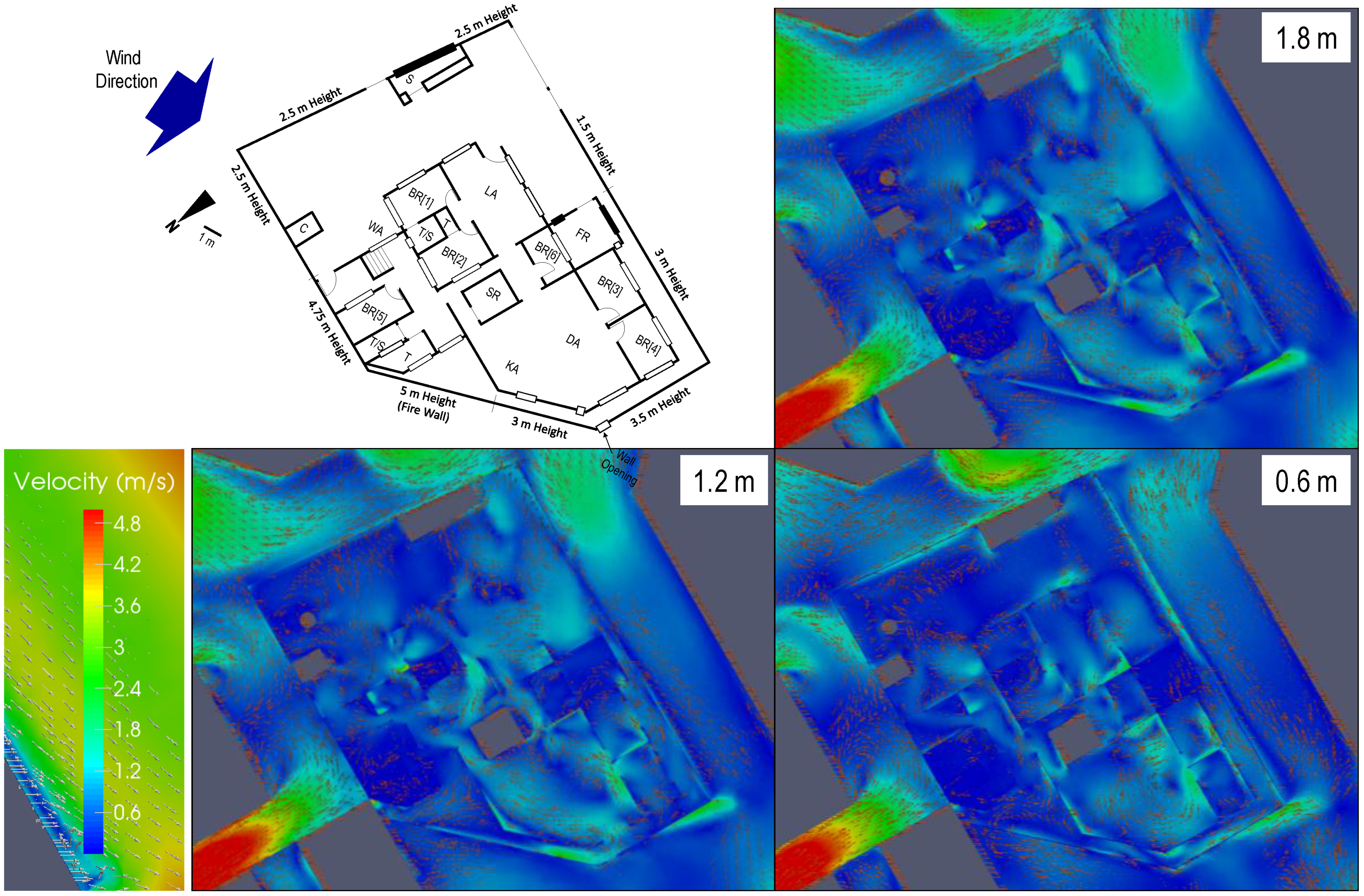
3.3. Effect of Left Wall Opening

Figure 11 shows the results for the case of a lot perimeter wall opening at the left side to increase the passage of air inside the house for cross flow, as the lot perimeter wall is high with the construction of the firewall as well on the left side of the house. Opening the lot perimeter wall at the left increases the wind in the living area, dining area, and kitchen area when compared with no lot perimeter wall opening, as shown in Figure 8, as the wind inside the house increases due to the passing of wind coming from the left of the house. It shows that the lot perimeter wall opening at the left increases the wind in bedroom 2. There is a reduction in wind passing bedrooms 3 and 4 due to some wind passing through the wall opening rather than through the windows of bedrooms 3 and 4, and going on to the living and kitchen areas. The opening of the lot perimeter wall at the left still could not resolve the low wind in bedrooms 5 and 6, as these rooms are located in a secluded part of the house.
Figure 12 shows the results when the lot perimeter wall at the left is opened to increase the wind passing through the house with all doors (main doors and bedroom doors) closed. The results show that the opening of the lot perimeter wall at the left contributes to the wind passing through the living area, dining area, and kitchen area compared with no lot perimeter wall opening, shown in Figure 10. With opened bedroom doors, the wind in the bedrooms is better than with closed bedroom doors (Figure 11).

3.4. General Results

Figure 13 shows the summary of results for the wind speed measured at the center of the bedrooms at the height of 1.2 m for the different test cases presented in this study. The result shows that Case 1, with a very low lot wall perimeter, has better wind for natural ventilation in the house rooms when compared to Case 2. The construction of the firewall at the back affects the wind field as it lessens the wind passing into the house, as shown in Cases 1, 2, and 3. Bedroom 5 still has a low wind speed due to its location, which is considered an inner bedroom. The increase of the lot perimeter wall height affects the wind around the house bedrooms. Considering the doors, it shows that opening the bedroom doors increase the cross flow ventilation in the bedrooms, particularly for bedrooms with windows on one side only, as presented in Cases 3, 4, and 5. The opening of the left wall of the lot perimeter wall has an effect on the cross ventilation in the bedroom, as shown in Case 6. However, closing the bedroom doors affects the cross ventilation as well, as is the same for different cases for closed bedroom doors, as shown in Case 7.

4. Conclusions

This paper presented the computational fluid dynamics (CFD) evaluation of the walled, detached family house which is typical in the Philippine tropical climate. It shows the wind field velocity before and after renovation, windows and wall openings, and the opening at the left of the lot perimeter wall that increases the wind passing through the house. With the CFD evaluation of the walled, detached family house, important conclusions are drawn.
  • The lot perimeter wall affects the wind field surrounding the house. The lot perimeter wall results in a decrease of fresh air coming inside the house and its surroundings. This will result in a reduction of natural ventilation and fresh air, and will increase discomfort and lower indoor air quality. Hence, this also results in the application of mechanical means such as air fans and air-conditioning systems that result in the increase of energy consumption of the house.
  • Opening the doors and windows is significant in the cross flow ventilation in the house, as shown in the different cases. As presented, it is very important to open the bedroom doors to increase the wind passing through the room for natural ventilation, particularly in the case of the rooms with windows on one side only.
  • To avoid air recirculation and stagnation, particularly in the detached house with a very high lot perimeter wall, it is important to consider opening some portion of the wall to increase the wind passing through the house to minimize air stagnation and recirculation that might result in poor ventilation and air quality. The opening at the left of the lot perimeter wall, as presented in the study, shows the increase in wind passing through the house.
The general results of the CFD simulation show the same observation presented by the house occupants. The house occupants discussed that bedrooms 5 and 6 have very low air ventilation, resulting in the use of air fans, particularly during summer time. The occupants also said that bedroom 1 has good ventilation, particularly when the door is opened during the nighttime. The occupants also stated that the construction of the firewall affected the house air flow and circulation. The researchers will conduct field measurement next summer upon getting support for the instrumentation and upon a discussion with the house owner relating to house improvement to increase air ventilation, as discussed in the paper.
The study shows that proper evaluation of the house design based on the evaluation of the lot perimeter wall, house windows and location of doors, and the house internal divisions is important in the utilization of natural ventilation based on the direction of the prevailing wind in the house surroundings. Based on other studies for natural ventilation in hot and humid climates, a wind speed above 1 m/s is needed to satisfy thermal comfort [6,16]. Hence, the present arrangement of the walled family detached house still needs mechanical ventilation or an air-conditioning system to satisfy the thermal comfort.
Thus, the application of a computational tool during the design phase, such as the CFD to visualize the effect of the different cases on the house, is important. It shows the application and usage of the CFD is very important in the house design based on the consideration of prevailing wind direction, neighborhood, lot location, house plan, and occupants’ expectations. Hence, this study is a pioneering step to improve house design in the tropical Philippines to increase the natural ventilation and air circulation and to minimize the usage of mechanical air-circulators and air-conditioning systems. With this, household energy consumption for mechanical air-circulators and air-conditioning systems will be reduced by using passive methods, as around 23% of household energy consumption is for space cooling and air-conditioning [1,2].

Acknowledgment

This research is supported by simFlow.

Author Contributions

NAE conceptualized the research and prepared this paper. OCE helped in data gathering and paper preparation.

Conflicts of Interest

The authors declare no conflict of interest.

References

  1. Enteria, N.; Cuartero, O. A Review of the Recent Development of the Philippine Household Technologies and Energy Consumption. Recent Patents Eng. 2017, 11, 35–48. [Google Scholar] [CrossRef]
  2. Enteria, N.; Awbi, H.; Yoshino, H. Application of Renewable Energy Sources and New Building Technologies for the Philippine Single Family Detached House. Int. J. Energy Environ. Eng. 2015, 6, 267–294. [Google Scholar] [CrossRef]
  3. Li, J.Q.; Ward, I.C. Investigation of Roof Pitch and Wind Induced Ventilation by Computational Fluid Dynamics. In Proceedings of the 23rd Conference on Passive and Low Energy Architecture, Geneva, Switzerland, 6–8 September 2006. [Google Scholar]
  4. Tam, N.V.; Trigaux, D.; Allacker, K.; Troyer, F.D. Optimization for Passive Design of Large Scale Housing Projects for Energy and Thermal Comfort in a Hot and Humid Climate. In Proceedings of the 30th International PLEA Conference, Ahmedabad, India, 16–18 December 2014. [Google Scholar]
  5. Ayata, T. Investigation of Building Height and Roof Effect on the Air Velocity and Pressure Distribution Around the Detached Houses in Turkey. Appl. Therm. Eng. 2017, 29, 1752–1758. [Google Scholar] [CrossRef]
  6. Wang, L.; Wong, N.H. Applying Natural Ventilation for Thermal Comfort in Residential Buildings in Singapore. Archit. Sci. Rev. 2007, 50, 224–233. [Google Scholar]
  7. Nugroho, A.M.; Ahmad, M.H.; Ossen, D.R. A Preliminary Study of Thermal Comfort in Malaysia’s Single Storey Terraced Houses. J. Asian Archit. Build. Eng. 2007, 6, 175–182. [Google Scholar] [CrossRef]
  8. Li, Y.; Heiselberg, P. Analysis methods for natural and hybrid ventilation—A critical literature review and recent developments. Int. J. Vent. 2003, 4, 3–20. [Google Scholar] [CrossRef]
  9. Mora-Pérez, M.; Guillén Guillamón, I.E.; López Jiménez, P.A.; López-Patiño, G. Natural Ventilation Building Design Approach in Mediterranean Regions: A Case Study at the Valencian Coastal Regional Scale (Spain). Sustainability 2016, 8, 855. [Google Scholar] [CrossRef]
  10. Linden, P.F. The fluid mechanics of natural ventilation. Annu. Rev. Fluid Mech. 2009, 31, 201–208. [Google Scholar] [CrossRef]
  11. BCA Green Mark. Appendix C: Ventilation Simulation Methodology and Requirement. In Certification Standard for New Buildings; Building and Construction Authority: Singapore, 2010. [Google Scholar]
  12. Baharum, M.A.; Surat, M.; Tawil, N.M.; Che-Ani, A.I. Modern Housing Tranquility in Malaysia from the Aspect of Thermal Comfort for Humid Hot Climate Zone. In E3S Web of Conferences; Emerging Technology for Sustainable Development Congress: Bangi, Malaysia, 2014. [Google Scholar]
  13. Mousli, K.; Semprini, G. An Investigation of Natural Ventilation in a Courtyard House to Achieve Thermal Comfort in Hot-Arid Climate. In Proceedings of the 9th International Conference on Indoor Air Quality Ventilation & Energy Conservation in Buildings, Songdo, Korea, 23–26 October 2016. [Google Scholar]
  14. Chu, Y.C.; Hsu, M.F.; Hsieh, C.M. A Field Assessment on Natural Ventilation and Thermal Comfort of Historical District—A Case of the Wugoushui Settlement in Taiwan. In Proceedings of the ICUC9—9th International Conference on Urban Climate jointly with 12th Symposium on the Urban Environment, Toulouse, France, 20–24 July 2015. [Google Scholar]
  15. Tablada, A.; Troyer, F.D.; Blocken, B.; Carmeliet, B.J.; Verschure, H. On Natural Ventilation and Thermal Comfort in Compact Urban Environments—The Old Havana Case. Build. Environ. 2009, 44, 1943–1958. [Google Scholar] [CrossRef]
  16. Cheng, V.; Ng, E. Wind for Comfort in High Density Cities. In Proceedings of the 25th Conference on Passive and Low Energy Architecture (PLEA 2008), Dublin, Ireland, 22–24 October 2008. [Google Scholar]
  17. Enteria, N. CFD Evaluation of Philippine Detached Structure with Different Roofing Designs. Infrastructures 2006, 1, 3. [Google Scholar] [CrossRef]
  18. Enteria, N.; Yoshino, H.; Mochida, A.; Takaki, R.; Yoshie, R.; Mitamura, T.; Baba, S. Synergization of Clean Energy Utilization, Clean Technology Development and Controlled Clean Environment Through Thermally Activated Desiccant Cooling System. In Proceedings of the 2008 ASME International Conference on Energy Sustainability, Jacksonville, FL, USA, 10–14 August 2008. [Google Scholar]
  19. OpenFOAM. Available online: http://www.openfoam.com/ (accessed on 14 December 2016).
  20. simFlow. Available online: https://sim-flow.com/ (accessed on 8 September 2016).
  21. Dose, B.; Medjroubi, W.; Stoevesandt, B. CFD Simulations of 2.5 MW Turbine using ANSYS CFX and Openfoam. In Proceedings of the First Symposium on OpenFOAM in Wind Energy, Oldenburg, Germany, 21 March 2013; Available online: http://www.forwind.de/sowe/Site/Program_files/SOWE2013_Dose.pdf (accessed on 23 January 2017).
  22. Casella, L.; Langreder, W.; Fisher, A.; Ehlen, M.; Skoutelakos, D. Dynamic Flow Analysis using an Openfoam based CFD Tool: Validation of Turbulence Intensity in a Testing Site. In Proceedings of the First Symposium on OpenFOAM® in Wind Energy, Oldenburg, Germany, 20–21 March 2013. [Google Scholar]
  23. Kerklaan, R.A.G. Design Tools for the Virtual Wind Tunnel Setting Up the Geometry for CFD Calculations. Master’s Thesis, Delft University of Technology, Delft, The Netherlands, 2006. [Google Scholar]
  24. Tamura, T.; Nozawa, K.; Kondo, K. AIJ Guide for Numerical Prediction of Wind Loads on Buildings. J. Wind Eng. Ind. Aerodyn. 2008, 96, 1974–1984. [Google Scholar] [CrossRef]
  25. Tominaga, Y.; Mochida, A.; Yoshie, R.; Kataoka, H.; Nozu, T.; Yoshikawa, M.; Shirasawa, T. AIJ Guidelines for Practical Applications of CFD to Pedestrian Wind Environment Around Buildings. J. Wind Eng. Ind. Aerodyn. 2008, 96, 1749–1761. [Google Scholar] [CrossRef]
  26. Franke, J.; Hellsten, A.; Schlunzen, H.; Carrissimo, B. (Eds.) Best Practice Guideline for the CFD Simulation of Flows in the Urban Environment; COST Office: Brussels, Belgium, 2007. [Google Scholar]
  27. Weather Spark. Average Weather in Davao Philippine. Available online: https://weatherspark.com/averages/33314/Davao-City-Davao-Region-Philippines (accessed on 26 July 2016).
  28. Irtaza, H.; Beale, R.G.; Godley, M.H.R.; Jameel, A. Comparison of Wind Pressure Measurement on Silsoe Experimental Building from Full-Scale Observation, Wind-Tunnel Experiments and Various CFD Techniques. Int. J. Eng. Sci. Technol. 2013, 5, 28–41. [Google Scholar] [CrossRef]
  29. Abohela, I.; Hamza, N.; Dehek, S. Effect of Roof Shape on Energy Yield and Positioning of Roof Mounted Turbines. In Proceedings of the 12th Conference of International Building Performance Simulation Association, Sydney, Australia, 14–16 November 2011. [Google Scholar]
  30. Blocken, B.; Stathopoulos, T.; Carmeliet, J. CFD Simulation of the Atmospheric Boundary Layer: Wall Function Problems. Atmos. Environ. 2007, 41, 238–252. [Google Scholar] [CrossRef]
Figure 1. Walled, detached family house: (a) floor plan and lot perimeter; (b) vertical description inside the house not including living area; and (c) vertical description for the living area only.
Infrastructures 02 00016 g001
Figure 2. Detached family house and lot perimeter 3D external and internal views.
Infrastructures 02 00016 g002
Figure 3. Computational model preparation: (a) computational domain and boundary conditions (B = H = 4 m); and (b) computational grid: (a) whole domain, and; (b) cube [17].
Infrastructures 02 00016 g003
Figure 4. Modeling and meshing of the detached family house together with the neighborhood: (a) wind velocity at different heights; (b) walled detached family house; (c) modeled house with neighborhood in computational domain, and; (d) mesh of modeled house with neighborhood.
Infrastructures 02 00016 g004
Figure 5. Simulation cases for the detached family house: Case (1) low lot perimeter wall (all windows and doors opened); Case (2) high lot perimeter wall (all windows and doors opened); Case (3) high lot perimeter wall with firewall (all windows and doors opened); Case (4) high lot perimeter wall and firewall (all windows and all internal doors opened); Case (5) high lot perimeter wall and firewall (all windows opened and all doors closed); Case (6) high lot perimeter wall and firewall with left lot perimeter wall opened (all windows and doors opened), and; Case (7): high lot perimeter wall and firewall with left lot perimeter wall opened (all windows opened and all doors closed).
Infrastructures 02 00016 g005
Figure 6. Case 1—Low lot perimeter wall (all windows and doors opened); wind velocity around and inside the detached family house for three vertical heights (1.8 m, 1.2 m, and 0.6 m above the floor).
Infrastructures 02 00016 g006
Figure 7. Case 2—High lot perimeter wall (all windows and doors opened) wind velocity around and inside the detached family house for three vertical heights (1.8 m, 1.2 m, and 0.6 m above the floor).
Infrastructures 02 00016 g007
Figure 8. Case 3—High lot perimeter wall with firewall (all windows and doors opened) wind velocity around and inside the detached family house for three vertical heights (1.8 m, 1.2 m, and 0.6 m above the floor).
Infrastructures 02 00016 g008
Figure 9. Case 4—High lot perimeter wall and firewall (all windows and all internal doors opened) wind velocity around and inside the detached family house for three vertical heights (1.8 m, 1.2 m, and 0.6 m above the floor).
Infrastructures 02 00016 g009
Figure 10. Case 5—High lot perimeter wall and firewall (all windows opened and all doors closed) wind velocity around and inside the detached family house for three vertical heights (1.8 m, 1.2 m, and 0.6 m above the floor).
Infrastructures 02 00016 g010
Figure 11. Case 6—High lot perimeter wall and firewall with left lot perimeter wall opened (all windows and doors opened) wind velocity around and inside the detached family house for three vertical heights (1.8 m, 1.2 m, and 0.6 m above the floor).
Infrastructures 02 00016 g011
Figure 12. Case 7—High lot perimeter wall and firewall with left lot perimeter wall opened (all windows opened and all doors closed, wind velocity around and inside the detached family house for three vertical heights (1.8 m, 1.2 m and 0.6 m above the floor).
Infrastructures 02 00016 g012
Figure 13. Wind speed at the center of the different bedrooms (BR) at the height of 1.2 m for the different cases of house renovation, combining door and window openings and taking into consideration the left wall opening (see Table 1 for more information of the different cases): (a) Floor plan, and; (b) Wind speed.
Infrastructures 02 00016 g013
Table 1. Simulation cases for the detached family house (See Figure 2 for walls location).
Front WallLeft WallFire WallWindowsFront Door & Back DoorBedrooms DoorLeft Wall Opening
Case 11.0 m & 1.0 m3.0 m1.0 mOpenedOpenedOpenedNo
Case 21.5 m & 3.0 m3.5 m3.0 mOpenedOpenedOpenedNo
Case 31.5 m & 3.0 m3.5 m5.0 mOpenedOpenedOpenedNo
Case 41.5 m & 3.0 m3.5 m5.0 mOpenedClosedOpenedNo
Case 51.5 m & 3.0 m3.5 m5.0 mOpenedClosedClosedNo
Case 61.5 m & 3.0 m3.5 m5.0 mOpenedOpenedOpenedYes
Case 71.5 m & 3.0 m3.5 m5.0 mOpenedClosedClosedYes

