Article

Design and Engineering Application of Flat-Bed Laminator for Photovoltaic Modules

1
Wuxi Zhichuangsheng Automation Equipment Co., Ltd., Wuxi 214101, China
2
Hebei Province Technology Innovation Center of Photovoltaic Module Manufacturing Equipment, Hebei Normal University of Science and Technology, Qinhuangdao 066001, China
*
Author to whom correspondence should be addressed.
Solar 2026, 6(3), 29; https://doi.org/10.3390/solar6030029
Submission received: 25 March 2026 / Revised: 8 May 2026 / Accepted: 20 May 2026 / Published: 24 May 2026
(This article belongs to the Topic Advances in Solar Technologies, 2nd Edition)

Abstract

Against the backdrop of the global energy transition and China’s dual-carbon strategy, the photovoltaic (PV) industry is entering a new stage of large-scale, intensive development, where efficiency improvement and cost control in module encapsulation have become the core of industrial competition. To address the drawbacks of traditional silicone plate laminators—frequent consumable replacement, high maintenance costs, and poor adaptability to dual-glass module encapsulation—this paper proposes a flat-plate laminator technical scheme. By replacing flexible silicone plates with rigid pressure plates and optimizing pressure transmission paths and sealing structures, we achieved efficient, low-cost lamination. We first compared the working principles of flat-plate and silicone plate laminators, completed the structural design of five core modules with an optimized rigid platen and annular silicone sealing system, developed a modular retrofitting scheme for existing equipment, and verified performance via engineering tests. Tests show that the retrofitted equipment achieves a module thickness deviation ≤ ±0.06 mm, a product yield of 99.88%, annual cost savings of USD 342,000 per unit, and a 0.61-year investment payback period. This work provides theoretical support and an engineering reference for technical innovation in PV module encapsulation equipment, with significant promotion and application value.

1. Introduction

Driven by the global energy transition and the “carbon peaking and carbon neutrality” policy framework [1,2], the photovoltaic (PV) industry has entered a new stage of large-scale, intensive development [3,4,5]. Against this backdrop, production efficiency and cost control in the module encapsulation process have emerged as the core focus of industrial competition [6,7]. As the core equipment for PV module encapsulation [8,9], the laminator fulfills its critical function by precisely regulating temperature, pressure, and vacuum level to drive the melting, flow, and curing of ethylene–vinyl acetate (EVA) adhesive film, thereby achieving robust bonding of multilayer materials including glass, solar cells, and backsheet. This lamination process directly determines the photoelectric conversion efficiency, mechanical strength, and service life of finished PV modules [10,11].
Conventional silicone rubber plate laminators are currently the mainstream equipment widely deployed in the PV industry, where lamination pressure is transmitted via the flexible deformation of the silicone rubber sheet [12,13]. However, this technology suffers from well-documented inherent limitations. Firstly, silicone membranes continuously operate at elevated temperatures ranging from 140 °C to 160 °C and are susceptible to corrosive acidic volatile gases generated by EVA encapsulant films. Such harsh operating conditions inevitably cause surface hardening and permanent indentation defects on silicone membranes [14,15,16]. Accordingly, regular replacement every three to six months is mandatory, which substantially increases material consumption costs and triggers additional production downtime losses. To mitigate these challenges, researchers have conducted extensive investigations from multiple technical perspectives. In terms of encapsulation materials, K. Liu et al. performed multi-condition high-temperature aging tests on EVA, POE, and EPE encapsulants, quantitatively revealing the material degradation mechanisms under diverse aging environments. Their results verified that POE exhibits superior thermal aging stability compared with other polymeric encapsulants [17]. In terms of lamination process optimization, Landa Pliquet et al. systematically explored the crosslinking characteristics of polyolefin elastomer encapsulants. Their research focused on material performance characterization and process parameter tuning, aiming to improve the curing quality and processing efficiency of polyolefin elastomers deployed in conventional membrane laminators [18]. Secondly, the silicone membrane lamination technique commonly suffers from uneven stress distribution at the four corners during the encapsulation of double-glass PV modules [19]. In practical manufacturing, additional customized pressure frames and silicone gaskets are necessarily equipped to alleviate this defect. The extra manual placement and recycling procedures further increase the overall encapsulation cost by 5–10%. To improve the encapsulation reliability and process compatibility of double-glass modules, Kyranaki et al. adopted polyolefin elastomers to enhance edge-sealing performance and anti-aging capability, and further proposed optimized lamination duration and process guidelines for industrial application [20]. Against the backdrop of the PV industry’s increasingly urgent demand for cost reduction and efficiency improvement, the development of novel laminators with superior pressure uniformity, low maintenance costs, and high process adaptability has emerged as the core direction for technological breakthroughs in the PV field [21]. It is noteworthy that to date, there are relatively few publicly available reports on the replacement of conventional flexible silicone membranes with rigid pressure plates and the realization of industrial-scale engineering application of this technology in both the academic community and the industrial sector.
Flat-plate lamination technology is an emerging lamination technology proposed in recent years. Its core innovation lies in the replacement of the conventional flexible silicone rubber plate with a rigid pressing plate, with uniform pressure transmission achieved via optimized mechanical structure and sealing design. This technology offers two prominent advantages: First, it completely eliminates the need for silicone rubber plate consumables, avoids production downtime losses caused by frequent component replacement, and significantly reduces equipment maintenance costs. Second, it enables direct lamination of bifacial double-glass modules without the additional deployment of specialized pressing frames and silicone gasket strips, thereby simplifying the production workflow. Nevertheless, two key technical bottlenecks remain for the industrial-scale engineering application of flat-plate lamination technology: First, the structural design of the rigid pressing plate must strike a balance between mechanical strength and pressure uniformity, to ensure consistent stress distribution across the entire module surface during the lamination process. Second, the realization of low-cost retrofitting for conventional silicone rubber plate laminators is to lower equipment renewal capital expenditure for PV manufacturing enterprises. Jiahui Zhu et al. took the flat-plate PV module laminator as the research object, conducted static mechanical analysis on the lamination plate under rated operating conditions, and performed steady-state thermal analysis and thermal–structural coupling analysis on the heating plate. They quantitatively verified that the deformation, stress, and temperature distribution of the core components all meet the requirements of the lamination process, confirmed the rationality of the structural design, and provided a theoretical reference for the structural design of the same type of laminators [22]. However, this study has only conducted limited investigations into the key engineering challenges of flat-plate laminators, including pressure uniformity control, sealing reliability, and dynamic fatigue life.
To address the aforementioned technical bottlenecks, this paper systematically details the working principle, structural design, and retrofitting scheme of the flat-plate laminator in conjunction with practical engineering case studies, and validates the equipment’s operational performance via full-scale engineering application data. This work aims to provide a critical technical reference for the industrial popularization and scaled application of flat-plate lamination technology, as well as for the technological advancement of PV module laminating equipment.

2. Working Principle and Main Structure of Flat-Bed Laminator

2.1. Comparison of Working Principles Between Flat-Plate Laminator and Silicone Rubber Plate Laminator

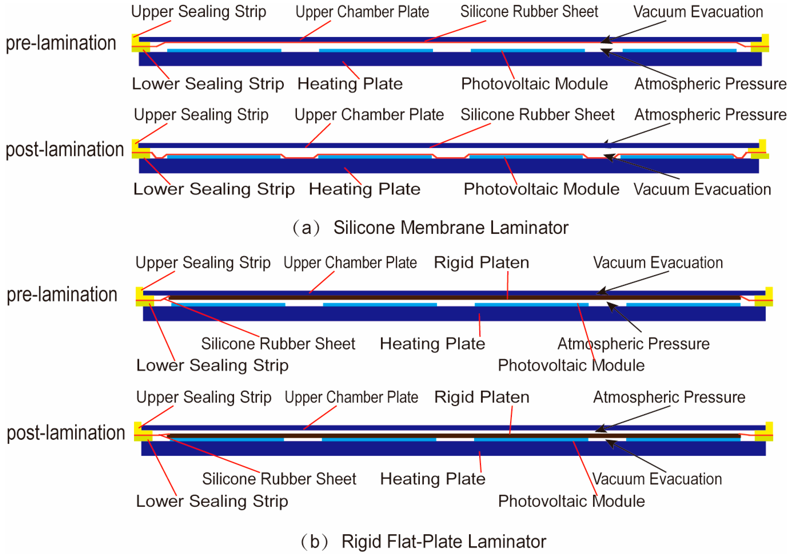
The core difference in working principle between the conventional silicone rubber plate laminator and the proposed flat-plate laminator lies in their pressure transmission mechanisms, with a detailed comparison provided in Figure 1. Figure 1a shows the schematic diagram of the conventional silicone rubber plate laminator. In this system, the silicone rubber plate is clamped by upper and lower pressing bars, achieving effective hermetic isolation between the lamination chamber and the external atmosphere. Concurrently, the silicone rubber plate partitions the lamination chamber into two independent upper and lower sub-chambers, with the PV module positioned in the lower sub-chamber. Prior to the lamination cycle, the upper sub-chamber is evacuated, while the lower sub-chamber remains vented to atmosphere. Driven by the resulting pressure differential, the silicone rubber plate is pressed tightly against the upper box plate surface, completing pre-lamination preparation. During the lamination stage, the upper sub-chamber is switched to atmospheric venting, while the lower sub-chamber is evacuated. Driven by the pressure differential between atmospheric pressure and the vacuum environment in the lower sub-chamber, the silicone rubber plate undergoes flexible deformation, conforming tightly to the surfaces of the PV module and heating plate, while uniformly transmitting pressure across the entire module area to achieve lamination of the multilayer materials. Concurrently, the vacuum environment simultaneously removes volatiles and entrapped gas generated during the lamination process, eliminating the risk of internal void defects within the module [23]. The core innovation of the proposed flat-plate laminator is the replacement of the conventional flexible silicone rubber plate with a rigid pressing plate, which enables a more direct and uniform pressure transmission path; its specific working principle is illustrated in Figure 1b. In this system, the silicone rubber plate is clamped by upper and lower pressing bars and forms a hermetic seal with the intermediate rigid pressing plate, which similarly partitions the lamination chamber into upper and lower sub-chambers, with the PV module positioned in the lower sub-chamber. Prior to the lamination cycle, the upper sub-chamber is evacuated, while the lower sub-chamber is vented to atmosphere. Driven by the induced pressure differential, the rigid pressing plate is forced tightly against the upper box plate under atmospheric pressure. During the lamination stage, the upper sub-chamber is vented to atmosphere, while the lower sub-chamber is evacuated. The resulting pressure differential drives the rigid pressing plate downward toward the module, where it conforms tightly to the surfaces of the module and heating plate. Benefiting from the high structural rigidity of the pressing plate, the non-uniform deformation defect inherent to the flexible silicone rubber plate is completely eliminated, enabling more consistent and uniform pressure transmission throughout the lamination cycle.

2.2. Structural Design of the Flat-Plate Laminator

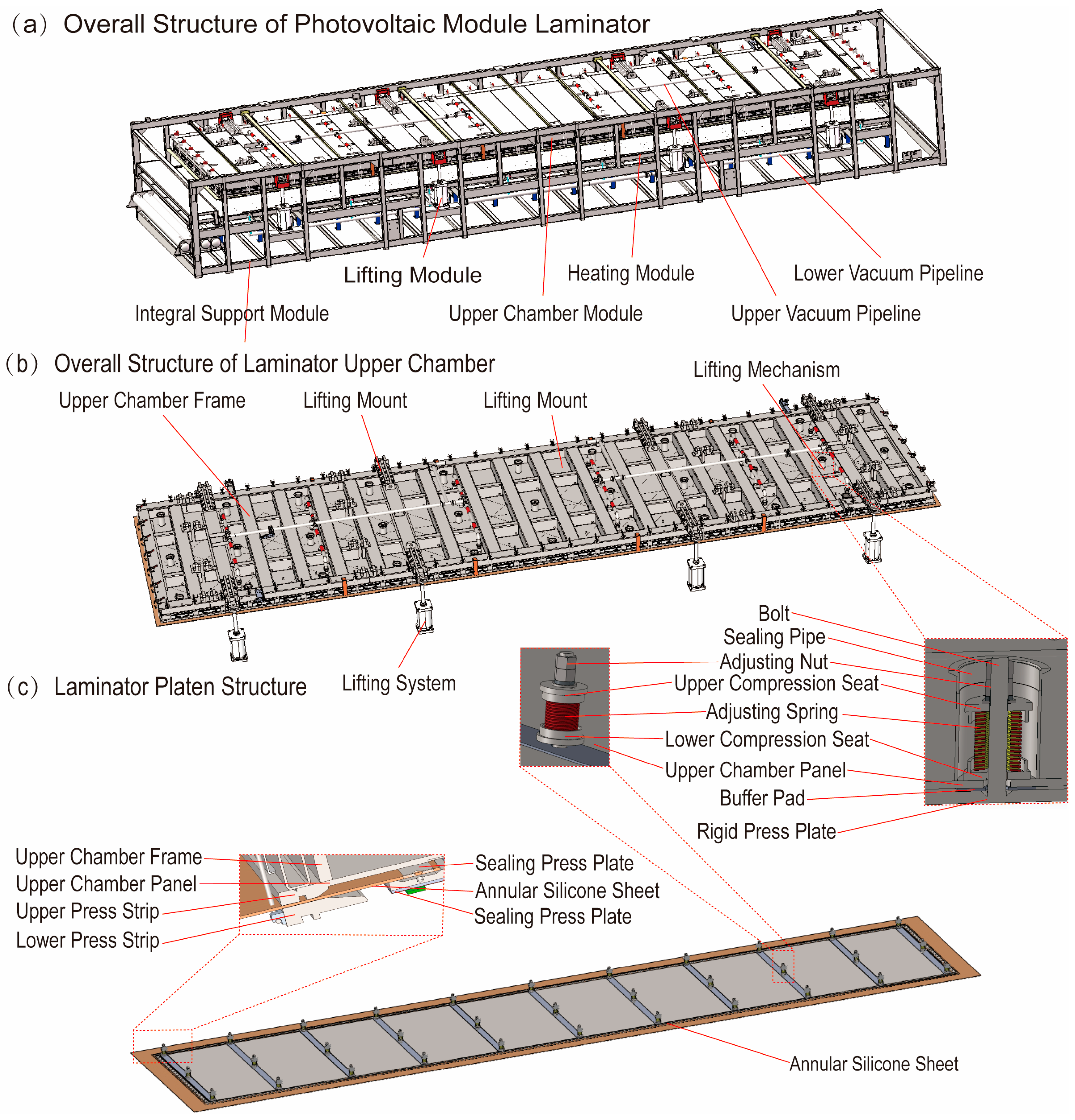
The overall architecture and core component details of the proposed flat-plate laminator are illustrated in Figure 2, with the complete equipment structure presented in Figure 2a. Its external profile and layout are fully consistent with those of conventional silicone rubber plate laminators, while its core structure is partitioned into five functional modules based on core operating roles: the integral support module, heating module, lifting module, upper box module, and sealing module. All modules operate in a coordinated manner to ensure precise regulation of temperature, pressure, and vacuum level throughout the full lamination cycle. The detailed structural design is elaborated as follows:
The main frame of the proposed flat-plate laminator is fabricated via welding of Q235 steel pipes and steel plates, and serves as a stable mounting base for all core components, including the upper box assembly, heating plate, and lifting system. By optimizing its structural rigidity design, the frame effectively eliminates deformation induced by vibration and pressure loads during equipment operation, thereby ensuring consistent motion accuracy and fitting stability of all mating components. The heating plate is precision-machined from a monolithic Q235 steel plate, and fixedly mounted on the upper section of the main frame, with a machined surface that conforms tightly to the PV module placement plane. The matched heating system offers three optional configurations, namely oil heating [24], electric heating [25], and electromagnetic heating [26]. This modular design enables flexible customization based on actual production scenario requirements, ensuring a stable, uniform heat source to support complete melting of the EVA adhesive film for module encapsulation. The lifting system is symmetrically mounted on both sides of the main frame, with its lifting base rigidly connected to the upper box frame. Lifting cylinders provide the driving power to achieve smooth opening and closing of the upper box assembly. This design enables precise regulation of the closing gap between the upper and lower box assemblies, providing a reliable foundation for high-precision chamber sealing and uniform pressure transmission during the subsequent lamination process.
The upper box module, the core actuation unit of the proposed flat-plate lamination technology, is divided into two integrated sub-systems, the upper box body system and the rigid plate pressing system, with a dedicated sealing structure serving as its core innovative component. The upper box body system is fabricated via welding of Q235 square steel tubes and steel plates, engineered to balance high structural rigidity and a robust sealing foundation while providing a stable mounting substrate for all components within the upper box assembly; the upper box plate, manufactured from a Q235 steel plate with identical dimensions to the heating plate, is welded and secured to the top of the upper box frame, with interconnected cross slits precision-machined on its bottom surface, through-holes drilled at the slit intersections to interface with vacuum pipelines routed along the top of the upper box plate, and all vacuum pipelines ultimately routed to a unified vacuum manifold interface, enabling precise evacuation and pressure regulation of the upper sub-chamber. The plate pressing system is built around a rigid pressing plate precision-machined from a monolithic Q235 steel plate, where an array of high-strength bolts is welded to the non-functional back surface of the rigid pressing plate; these bolts pass through pre-machined through-holes in the upper box plate and are assembled in sequence with a lower compression seat, adjustable preload spring, and upper compression seat, with the terminal ends locked via precision adjustment nuts, such that high-precision levelness calibration and smooth vertical actuation of the rigid pressing plate are achieved by tuning the preload compression of the adjustable springs, while a compliant buffer layer laid on the working surface of the rigid pressing plate is designed to ensure uniform pressure transmission and damp transient impact loads, thereby mitigating the risk of solar cell microcracks induced by rigid hard contact. During the lamination process, the vacuum level of the lower chamber is set to 50–50,000 Pa, while the upper chamber is directly vented to the ambient atmosphere, thus forming a differential pressure of approximately −101 to −51 kPa across both sides of the rigid pressure plate. This differential pressure serves as the primary pressure source that drives the pressure plate to move downward and apply pressure to the surface of the PV module. To meet the process requirements of different modules, linear adjustment of the initial contact pressure between the pressure plate and the module within the range of 0.5–20 kPa can be achieved by adjusting the air flow rate of the upper chamber connected to the atmosphere or adding a throttle valve. Accordingly, the bolt-spring connection assembly undergoes a complete alternating tension–compression stress cycle in each lamination cycle, with a stress amplitude of approximately 45–55 MPa. The annual number of cycles reaches about 52,000 under 24 h continuous lamination operation. To satisfy the aforementioned requirements for dynamic characteristics and fatigue resistance, connecting bolts made of 40CrNiMoA alloy steel and adjustment springs made of 60Si2MnA alloy steel are selected. Replacing the traditional monolithic silicone membrane with an annular silicone membrane in the sealing structure between the heating plate and the upper chamber is a key innovation of the rigid plate lamination technology. The outer perimeter is hermetically clamped and secured between upper and lower compression bars, with the upper compression bar continuously welded along the full perimeter of the upper box plate and the detachable lower compression bar mated tightly to the upper bar via high-torque fasteners, while the inner perimeter of the annular silicone rubber sheet is hermetically sealed to the rigid pressing plate via a dedicated sealing clamp plate to establish a redundant dual-sealing architecture; this structure effectively partitions the lamination chamber into hermetically isolated, fully independent upper and lower sub-chambers, guaranteeing long-term stability of the vacuum environment and reliable, consistent pressure transmission throughout the entire lamination cycle. After the pressure plate is fully closed during lamination, the nominal contact stress on the sealing interface of the annular silicone sealing system must be maintained within 1.5–4 MPa to ensure no external gas leakage during the vacuum holding phase. During each lamination cycle, the annular silicone seal undergoes periodic compression–rebound deformation accompanying the reciprocating lifting motion of the rigid pressure plate, with its compression ratio controlled at 20–40%. The selected annular silicone membrane fully meets the above process requirements, with a designed replacement cycle of no less than 0.5 years.
Based on the aforementioned structural design, the core operational cycle of the proposed flat-plate laminator is systematically subdivided into three sequential stages: pre-lamination, in-lamination, and post-lamination:
During the pre-lamination stage of the proposed flat-plate laminator, evacuation of the upper sub-chamber is performed via the unified vacuum manifold interface, while the lower sub-chamber remains vented to the ambient atmosphere. Driven by the resulting pressure differential, the rigid pressing plate is forced tightly against the bottom surface of the upper box plate under atmospheric pressure. The lifting cylinders subsequently actuate to drive the upper box assembly to open, and the PV module is loaded onto the precision-machined surface of the heating plate.
During the in-lamination stage of the proposed flat-plate laminator, the upper box assembly is fully closed, and the annular silicone rubber sheet forms a hermetically sealed lamination chamber via the redundant dual-sealing architecture at its outer and inner perimeters. The upper sub-chamber is switched to vent to ambient atmosphere, while the lower sub-chamber is simultaneously evacuated. Driven by the resulting pressure differential established between the upper and lower sub-chambers, the rigid pressing plate moves vertically toward the PV module and conforms tightly to the module surface. Benefiting from the high inherent structural rigidity of the pressing plate, uniform pressure is consistently transmitted across the entire active area of the module. Meanwhile, the heating system delivers continuous, uniform heat to fully melt the EVA adhesive film, and the vacuum environment simultaneously extracts entrapped interlayer air and volatiles generated during the melting process, ultimately achieving robust, void-free bonding and curing of the module’s multilayer encapsulation materials.
During the post-lamination stage of the proposed flat-plate laminator, the lower sub-chamber is vented to ambient atmosphere via the unified vacuum manifold interface, while the upper sub-chamber is simultaneously evacuated. Driven by the resulting pressure differential, the rigid pressing plate is forced tightly against the bottom surface of the upper box plate under atmospheric pressure. The lifting cylinders subsequently actuate to drive the upper box assembly to open, and the fully cured and laminated PV module is unloaded from the lamination chamber.

2.3. Retrofitting Scheme

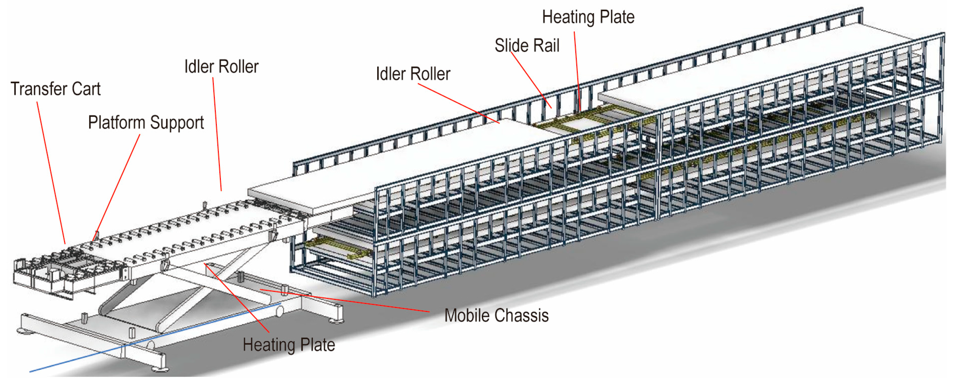
The proposed flat-plate laminator offers two industrial application modes: direct deployment of newly fabricated complete equipment, and retrofitting of conventional silicone rubber plate laminators. Of these two modes, the retrofitting scheme is better aligned with the practical industrial demands of PV manufacturers for cost reduction and efficiency enhancement, owing to its lower capital expenditure, shorter on-site implementation cycle, and faster investment return. The detailed retrofitting scheme is developed based on the modular structural design illustrated in Figure 3. This scheme eliminates the need for structural modifications to the original equipment’s main frame, heating plate body, and lifting drive system, and only requires rapid replacement and adaptive matching of the original upper box assembly with the newly designed upper box module via dedicated transfer tooling, enabling a highly efficient retrofitting workflow with minimal disruption to existing production line operations. The step-by-step retrofitting procedures are elaborated as follows.

2.3.1. Pre-Retrofitting Preparation

The complete upper box assembly of the proposed flat-plate laminator is fully prefabricated in the workshop prior to on-site deployment, including the pre-assembly and commissioning of all core components: the upper box frame, rigid pressing plate assembly, annular sealing structure, and vacuum pipelines. This prefabrication workflow ensures that the overall performance of the upper box module fully meets the specified technical requirements, with the assembly fully prepared for direct on-site installation and deployment. Concurrently, on-site pre-retrofitting preparation is completed: auxiliary protective structures, conveyor roller tables, and other components in the existing production line that interfere with the laminator upper box are removed, on-site sundries around the equipment are cleared, and sufficient transfer and operation space is reserved to guarantee the smooth execution of the entire retrofitting process.

2.3.2. Removal and Transfer of the Original Upper Box

The dedicated transfer cart is maneuvered to the designated position at the front end of the laminator. This transfer cart is equipped with a bottom mobile base, hydraulic lifting mechanism, platform support, and anti-slip guide rollers, enabling horizontal positioning, height fine-tuning, and stable transfer of the upper box module, thereby effectively reducing manual labor intensity and eliminating the risk of impact damage to precision components during the transfer process. First, auxiliary components including the unified vacuum manifold interface and electrical wiring harnesses of the upper box assembly on the conventional silicone rubber plate laminator are removed, and all mechanical and electrical connections between the upper box assembly and the lifting system, as well as the control system, are disconnected to ensure zero structural interference during the disassembly process. Sliding rails with matched specifications are evenly laid on the heating plate surface to provide stable support for the horizontal transfer of the upper box assembly and prevent scratching of the heating plate’s precision working surface. Via the equipment’s native lifting system, the original upper box assembly is slowly lowered onto the sliding rails, the connecting structure between the upper box assembly and the lifting base is unlocked, and the upper box assembly is towed via a winch to translate along the rails onto the platform support of the transfer cart, with auxiliary positioning and guidance provided by the cart’s anti-slip guide rollers. The hydraulic lifting mechanism is subsequently actuated to fine-tune the transfer height, and the decommissioned original upper box assembly is stably transferred to and secured in the designated storage area.

2.3.3. Installation and Adaptation of the New Upper Box Module

The prefabricated upper box module of the proposed flat-plate laminator is hoisted and secured onto the platform support of the dedicated transfer cart. The cart is precisely maneuvered via its mobile base to align the new upper box assembly with the mounting reference datum of the laminator main frame, while the hydraulic lifting mechanism is actuated to fine-tune the module height, ensuring an exact match between its connection interface and the equipment’s native lifting system. The new upper box assembly is then towed via the winch to translate along the pre-laid sliding rails to the position directly above the laminator main frame, with its planar position fine-tuned to achieve full coaxial alignment of all connection holes between the upper box frame and the lifting base, thus guaranteeing high-precision installation accuracy. The new upper box assembly is rigidly coupled to the lifting base of the lifting system, with all connecting bolts torqued to the specified technical requirements to ensure sufficient mechanical connection strength and long-term structural stability. Subsequently, the unified vacuum manifold pipelines and electrical wiring harnesses are connected and functionally verified, and signal communication between the new upper box module and the equipment control system is fully restored and commissioned, completing the core structural and functional installation. Upon completion of commissioning, the sliding rails on the heating plate surface are removed, grease residues and process debris on all equipment surfaces are thoroughly cleaned, and the production line’s auxiliary protective structures are fully restored to their normal operating state.

3. Engineering Application

3.1. Retrofitting Engineering Application

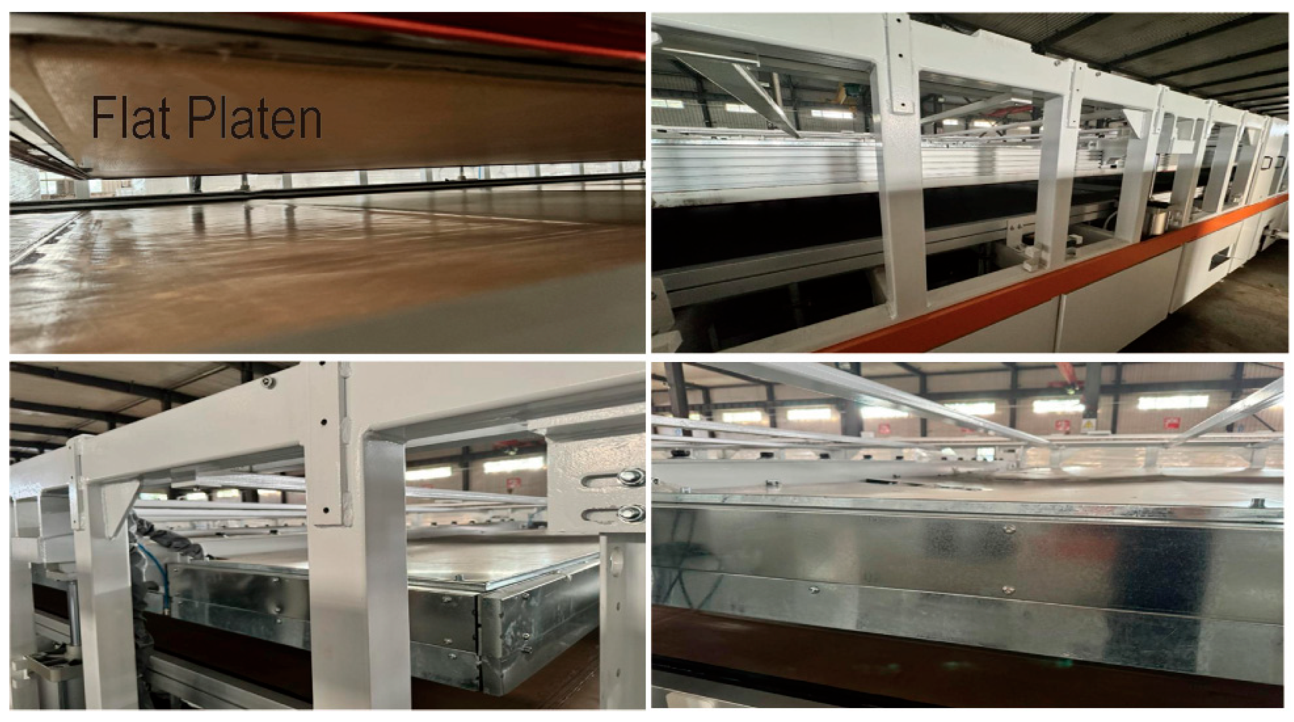
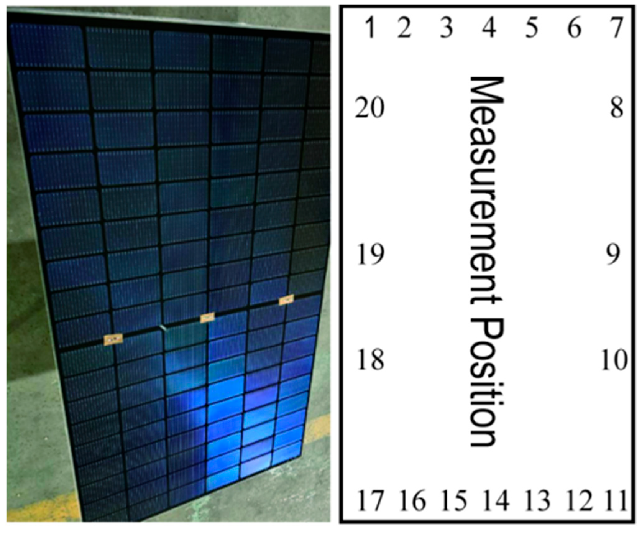
A commercial 27115 conventional silicone rubber plate laminator from a mass-production PV manufacturer was selected for retrofitting with the proposed flat-plate lamination technology, and a photograph of the retrofitted full-scale equipment is presented in Figure 4. To systematically verify the process adaptability, long-term operational stability, and mass production efficiency of the retrofitted equipment, a 12-month continuous full-scale production trial was conducted, with module thickness uniformity and finished product yield selected as the core performance monitoring indicators. Module thickness uniformity is a core metric for evaluating the pressure transmission performance of a laminator, which directly determines the long-term structural stability and optoelectronic performance of finished PV modules. For this test, five PV modules fabricated by the retrofitted laminator were randomly selected, with 16 uniformly distributed test points arranged on each module (as illustrated in Figure 5); the thickness of each test point was measured using a digital micrometer with a measurement accuracy of 0.01 mm, and the corresponding test results are summarized in Table 1. The test results demonstrate that the average thickness of the five tested modules ranges from 4.895 mm to 4.900 mm, with a maximum thickness deviation of ≤±0.06 mm across all modules, which is well within the ≤±0.3 mm threshold specified in the mainstream PV industry standard [27]. This confirms that the proposed flat-plate laminator delivers superior pressure transmission uniformity and can reliably guarantee high consistency of module encapsulation quality. Over the full 12-month production trial spanning the 2025 calendar year, the retrofitted 27115 flat-plate laminator fabricated a total of 276,500 finished PV modules, of which only 335 units were classified as defective or downgraded products, corresponding to an ultra-low overall defect rate of 0.12%. The primary failure modes of these defective modules were identified as module edge voids (128 units) and solar cell microcracks (87 units), and subsequent root cause analysis confirmed that these defects could be completely eliminated via process optimization, specifically by tuning the vacuum evacuation duration and adjusting the spring preload of the rigid pressing plate.

3.2. Product Performance Analysis

During the 12-month continuous industrial production trial, the rigid flat-plate laminator exhibited multiple application advantages over the conventional silicone membrane laminator. While maintaining the same product yield as the conventional equipment, the proposed laminator achieved a significant improvement in PV module thickness uniformity, with better compatibility for double-glass PV module lamination. Meanwhile, it completely eliminated the consumption of silicone membrane consumables, thus avoiding the downtime losses caused by frequent replacement of consumables. The differences in core functions and performance between the conventional silicone membrane laminator and the rigid flat-plate laminator, including pressure transmission mode, PV module thickness uniformity, and product yield, are shown in Table 2.

3.3. Economic Benefit Analysis

Based on the actual operational data of the modified equipment, a comprehensive economic benefit analysis of the flat-plate PV module laminator was conducted, covering core cost dimensions including consumable materials, labor, and energy consumption. The modification eliminates the use of silicone sheets, with 18 silicone sheets saved annually. Calculated at a unit price of 2000 USD per sheet, this translates to an annual material cost reduction of 36,000 USD. Meanwhile, the requirement for pressure frames and corner protectors for double-glass PV modules is removed, which further cuts down consumable input. The conventional silicone sheet lamination process requires two operators per shift for corner protector placement and one operator per shift for silicone sheet replacement, while all the above positions are completely eliminated after the modification. Based on the three positions per shift configuration and an annual salary of 45,000 USD per person, the modification achieves an annual reduction of three full-time positions, corresponding to an annual labor cost saving of 135,000 USD. For a modified production unit consisting of two pieces of equipment, a more significant labor cost reduction can be realized with a labor cut of seven operators per shift in the vertical configuration. For the conventional process, each silicone sheet replacement causes 3 h of downtime per chamber, resulting in a total annual downtime of 54 h for the replacement of 18 silicone sheets. In contrast, no downtime for silicone sheet replacement is required after the modification. With a rated production capacity of 49 modules per hour and an effective capacity utilization rate of 85%, the modification enables an additional annual output of 2249 modules, thus generating extra economic benefits.
The total annual cost savings for a single retrofitted equipment unit amount to USD 171,000, all of which are derived from consumable and labor cost reductions: specifically, USD 36,000 from the elimination of silicone rubber plate consumable expenses, and USD 135,000 from labor cost cuts. The economic benefits become even more prominent when the revenue from production increment is factored in. Calculated on the basis of one complete retrofitting unit (consisting of two equipment units), the total annual cost savings reach USD 342,000.
An investment return analysis was performed to quantify the economic viability of the proposed flat-plate lamination retrofitting technology. The upfront initial capital investment for one complete retrofitting unit (covering two equipment units) is USD 207,000, an all-inclusive cost covering the prefabrication of flat-plate upper box modules, rental of dedicated transfer equipment, on-site construction and retrofitting works, control system upgrade, and all other associated ancillary costs. The static payback period, a core metric for evaluating investment economics in the PV manufacturing industry, is calculated via the standard engineering economic formula defining payback period as upfront initial capital investment divided by annual net cost savings; substituting the verified economic data into this calculation yields a payback period of USD 207,000/USD 342,000 per year ≈ 0.61 years, which is significantly shorter than the industry-average level, demonstrating the outstanding economic return and high investment value of the proposed retrofitting scheme.

4. Conclusions

This paper systematically addresses the inherent technical limitations of conventional silicone rubber plate laminators, namely frequent consumable replacement requirements, high operation and maintenance costs, and insufficient encapsulation adaptability for high-efficiency bifacial double-glass PV modules. A comprehensive and systematic investigation is conducted on the structural design, retrofitting scheme optimization, and full-scale engineering application verification of the proposed flat-plate laminator, with the core research conclusions summarized as follows:
  • The proposed flat-plate laminator replaces the conventional flexible monolithic silicone rubber plate with a precision-machined rigid pressing plate, which, in conjunction with a redundant dual-sealing architecture based on an annular silicone rubber sheet, achieves uniform and stable pressure transmission across the entire PV module area. This design fundamentally addresses the core pain points of excessive consumable and labor costs inherent to the conventional silicone rubber plate lamination process. For the retrofitted equipment, the maximum thickness deviation of mass-produced PV modules is ≤±0.06 mm, with a finished product yield reaching 99.88%; these performance metrics fully satisfy the high-precision encapsulation requirements for commercial PV module manufacturing.
  • The proposed modular retrofitting scheme eliminates the need for structural modifications to the core mechanical and drive systems of the original in-service equipment, with the entire retrofitting workflow completed solely via rapid replacement of the original upper box assembly with the newly designed flat-plate upper box module. This scheme delivers prominent advantages including low retrofitting capital expenditure, short on-site implementation cycle, and minimal disruption to existing production line operations, offering a highly efficient, technically feasible and cost-effective solution for performance and technology upgrading of in-service conventional silicone rubber plate laminators.
  • The economic benefit analysis demonstrates that a single retrofitting unit (comprising two pieces of equipment) delivers an annual cost saving of USD 342,000, with a payback period as short as 0.61 years. In addition, this retrofitting scheme substantially reduces consumable consumption and labor input, while significantly improving production efficiency. Such performance is fully aligned with the cost reduction and efficiency improvement requirements for the large-scale and intensive development of the PV industry.

5. Limitations and Future Work

5.1. Limitations

In this study, a conventional silicone membrane laminator was successfully retrofitted into a rigid flat-plate laminator, and systematic research was conducted on the structural design, retrofitting scheme optimization, and engineering application verification of the rigid plate laminator. A 1-year continuous production validation test was carried out on the retrofitted rigid plate laminator, which confirmed that the equipment fully meets the requirements for large-scale PV module production using the laminator. However, this study still has the following limitations:
  • The retrofitting and validation in this work were conducted on only a single set of laminator equipment. The obtained results may be affected by factors including the wear degree and assembly tolerance of this specific laminator model, and the reproducibility of the results on other laminators of the same type remains to be verified.
  • The continuous production validation test conducted in this study only covers PV modules of a single specification. Therefore, further verification is required to confirm whether the retrofitting scheme can maintain its effectiveness in pressure uniformity, edge effect, and tooling compatibility when adapted to PV modules with different dimensions.

5.2. Future Work

To address the aforementioned limitations, future research can be conducted on the following aspects:
  • Retrofitting and validation will be performed on multiple sets of laminator equipment of the same model with different service ages and wear conditions, and statistical comparative analysis will be carried out to systematically evaluate the reproducibility of the proposed scheme across the equipment population.
  • Continuous production tests will be conducted on PV modules of different specifications to verify the process adaptability, operational stability, and production efficiency of the retrofitted rigid flat-plate laminator for PV modules.
  • Systematic full life cycle assessment of the rigid plate laminator will be conducted to quantify its environmental benefits in terms of material consumption, energy utilization, carbon emissions, and waste generation.

Author Contributions

Conceptualization, Y.J., P.D. and B.S.; methodology, Y.J.; software, Y.J.; validation, P.D. and Y.J.; formal analysis, Y.J.; investigation, B.S.; resources, P.D.; data curation, Y.J. and B.S.; writing—original draft preparation, Y.J.; writing—review and editing, Y.J.; visualization, Y.J.; supervision, P.D.; project administration, P.D.; funding acquisition, Y.J. All authors have read and agreed to the published version of the manuscript.

Funding

This research was funded by the Post-graduate’s Innovation Fund Project of Hebei Province (No. CXZZ202610).

Data Availability Statement

The original contributions of this study are contained herein. For further inquiries, please contact the corresponding author.

Acknowledgments

This study extends its sincere gratitude to all individuals who provided valuable insights and suggestions.

Conflicts of Interest

Authors Yu Jin, Pengju Duan, and Boda Song were employed by the company Wuxi Zhichuangsheng Automation Equipment Co., Ltd. The authors declare that the research were conducted in the absence of any commercial or financial relationships that could be construed as a potential conflict of interest.

Abbreviations

PVPhotovoltaic
EVAEthylene–vinyl acetate

References

  1. Wang, Y.; Wang, R.; Tanaka, K.; Ciais, P.; Penuelas, J.; Balkanski, Y.; Sardans, J.; Hauglustaine, D.; Cao, J.; Chen, J.; et al. Global spatiotemporal optimization of photovoltaic and wind power to achieve the Paris Agreement targets. Nat. Commun. 2025, 16, 2127. [Google Scholar] [CrossRef]
  2. Wen, D.; Gao, W.; Qian, F.; Gu, Q.; Ren, J. Development of solar photovoltaic industry and market in China, Germany, Japan and the United States of America using incentive policies. Energy Explor. Exploit. 2021, 39, 1429–1456. [Google Scholar] [CrossRef]
  3. Wang, S.; Xu, Q.; He, Y.; Wang, Y.; Liu, C.; Zhang, Y. Environmental Impact Assessment of the Photovoltaic Industry Based on LCA. Pol. J. Environ. Stud. 2025, 35, 2355–2375. [Google Scholar] [CrossRef]
  4. Luo, Z.; He, J.; Hu, S. Driving force model to evaluate China’s photovoltaic industry: Historical and future trends. J. Clean. Prod. 2021, 311, 127637. [Google Scholar] [CrossRef]
  5. Zou, H.; Du, H.; Ren, J.; Sovacool, B.K.; Zhang, Y.; Mao, G. Market dynamics, innovation, and transition in China’s solar photovoltaic (PV) industry: A critical review. Renew. Sustain. Energy Rev. 2017, 69, 197–206. [Google Scholar] [CrossRef]
  6. Ellis, S.; Maple, L.; Shimpi, T.; Pavgi, A.; Tamizhmani, G.; Sampth, W.; Barth, K. Reliability and Manufacturing Demonstrations of a New Photovoltaic Module Architecture and Streamlined Approach to Encpasulation. In Proceedings of the 2021 IEEE 48th Photovoltaic Specialists Conference (PVSC); IEEE: Piscataway, NJ, USA, 2021; pp. 1504–1506. [Google Scholar]
  7. Govaerts, J.; Borgers, T.; Luo, B.; Van Dyck, R.; van der Heide, A.; Reekmans, B.; Vastmans, L.; Moors, R.; Doumen, G.; Tous, L.; et al. Interconnection and lamination technologies towards ubiquitous integration of photovoltaics. Prog. Photovolt. Res. Appl. 2023, 31, 1114–1129. [Google Scholar] [CrossRef]
  8. Sraisth, S. Achieving faster lamination process for crystalline photovoltaic modules by using latest lamination technologies. In Proceedings of the 33rd European Photovoltaic Solar Energy Conference and Exhibition, Amsterdam, The Netherlands, 25–29 September 2017; pp. 992–997. [Google Scholar]
  9. Sraisth; Mansour, D.E.; Öz, A.K.; Gebhardt, P.; Klaus, D.; Wellens, C.; Sraisth, S. Reducing process time of PV module lamination by using double-side heating system. EPJ Photovolt. 2025, 16, 26. [Google Scholar] [CrossRef] [PubMed]
  10. Lee, I.B.; Kim, Y.; Kim, S. A Data-Driven Machine Vision Framework for Quality Management in Photovoltaic Module Manufacturing. Machines 2025, 13, 285. [Google Scholar] [CrossRef]
  11. Li, H.-Y.; Théron, R.; Röder, G.; Turlings, T.; Luo, Y.; Lange, R.F.; Ballif, C.; Perret-Aebi, L.-E. Insights into the Encapsulation Process of Photovoltaic Modules: GC-MS Analysis on the Curing Step of Poly (ethylene-co-vinyl acetate) (EVA) Encapsulant. Polym. Polym. Compos. 2012, 20, 665–672. [Google Scholar] [CrossRef]
  12. Bragagnolo, J.A.; Akita, J.; Takahashi, H.; Sugiyama, I.; Chikaki, Y.; Ito, M. Durasheet-a new high durability diaphragm sheet. In Proceedings of the 3rd World Conference on Photovoltaic Energy Conversion 2003, Osaka, Japan, 11–18 May 2003; IEEE: Piscataway, NJ, USA, 2003; Volume 2, pp. 1964–1967. [Google Scholar]
  13. Lange, R.F.M.; Luo, Y.; Polo, R.; Zahnd, J. The lamination of (multi) crystalline and thin film based photovoltaic modules. Prog. Photovolt. Res. Appl. 2011, 19, 127–133. [Google Scholar] [CrossRef]
  14. Zhang, Z.; Zhang, Z.; Yue, S.; Jiang, X.; Hu, J. Performance characteristics of silicone rubber for use in acidic environments. Polymers 2023, 15, 3598. [Google Scholar] [CrossRef] [PubMed]
  15. Wang, Y.; Qiu, X.; Zheng, J. Effect of the sheet size on the thermal stability of silicone rubber–reduced graphene oxide nanocomposites. J. Appl. Polym. Sci. 2019, 136, 47034. [Google Scholar] [CrossRef]
  16. Sultan, B.Å.; Sörvik, E. Thermal degradation of EVA and EBA—A comparison. I. Volatile decomposition products. J. Appl. Polym. Sci. 1991, 43, 1737–1745. [Google Scholar] [CrossRef]
  17. Liu, K.; Miller, D.C.; Bosco, N.; Newkirk, J.M.; Sakamoto, T.; Dauskardt, R.H. Investigating the Crosslinking, Degradation, and Adhesion Behavior of Photovoltaic Encapsulants Under Thermal Accelerated Aging. IEEE J. Photovolt. 2025, 15, 309–319. [Google Scholar] [CrossRef]
  18. Landa-Pliquet, M.; Béjat, T.; Serasset, M.; Descormes, A.; Mofakhami, E.; Voroshazi, E. Enhancing photovoltaic modules encapsulation: Optimizing lamination processes for Polyolefin Elastomers (POE) through crosslinking behavior analysis. Sol. Energy Mater. Sol. Cells 2024, 267, 112725. [Google Scholar] [CrossRef]
  19. Slauch, I.M.; Vishwakarma, S.; Tracy, J.; Gambogi, W.; Meier, R.; Rahman, F.; Hartley, J.Y.; Bertoni, M.I. Manufacturing induced bending stresses: Glass-glass vs. glass-backsheet. In Proceedings of the 2021 IEEE 48th Photovoltaic Specialists Conference (PVSC); IEEE: Piscataway, NJ, USA, 2021; pp. 1943–1948. [Google Scholar]
  20. Kyranaki, N.; Perrin, L.; Flandin, L.; Planès, E.; Farha, C.; Wagner, L.; Saddedine, K.; Martineau, D.; Cros, S. Comparison of glass–glass versus glass–backsheet encapsulation applied to carbon-based perovskite solar cells. Processes 2023, 11, 2742. [Google Scholar] [CrossRef]
  21. Sraisth, S.; Öz, A.K.; Klaus, D.; Wellens, C.; Heinrich, M. Influence of the lamination pressure on the adhesion, degree of cross-linking, and bubble formation of PV modules. In Proceedings of the 8th World Conference on Photovoltaic Energy Conversion, Milan, Italy, 26–30 September 2022; pp. 823–829. [Google Scholar]
  22. Zhu, J.; Shi, L.; Zhang, K.; Li, S.; Chen, L. Structural Analysis of Key Components of Plate Type Solar Cell Module Laminator. Int. Core J. Eng. 2021, 7, 320–327. [Google Scholar]
  23. Li, H.; Perret-Aebi, L.; Chapuis, V.; Ballif, C.; Luo, Y. The effect of cooling press on the encapsulation properties of crystalline photovoltaic modules: Residual stress and adhesion. Prog. Photovolt. Res. Appl. 2015, 23, 160–169. [Google Scholar] [CrossRef]
  24. Niu, L.; Cai, Z.; Zhang, M.; Yuan, H.; Li, J.; Suo, X. Design and application of composite PID control in laminator heating system. In Proceedings of the 2011 2nd International Conference on Artificial Intelligence, Management Science and Electronic Commerce (AIMSEC); IEEE: Piscataway, NJ, USA, 2011; pp. 3848–3851. [Google Scholar]
  25. Rahmoun, I.; Le Carre, T.; Chambion, B.; Mofakhami, E.; Derrier, A.; Bouvard, J.-L.; Bouchard, P.-O. 3-D modeling of thermal exchange in the PV module during lamination: Impact of architecture, laminator configuration, and lamination recipe. IEEE J. Photovolt. 2021, 12, 107–113. [Google Scholar] [CrossRef]
  26. Shi, L.; Liu, Y.; Duan, P.; Zhang, L.; Li, A. Optimization of Temperature Uniformity in Photovoltaic Laminators Based on Electromagnetic Induction Heating. Energies 2025, 18, 6096. [Google Scholar] [CrossRef]
  27. Wu, D.; Wessel, P.; Zhu, J.; Montiel-Chicharro, D.; Betts, T.R.; Mordvinkin, A.; Gottschalg, R. Influence of lamination conditions of EVA encapsulation on photovoltaic module durability. Materials 2023, 16, 6945. [Google Scholar] [CrossRef] [PubMed]
Figure 1. Comparison between membrane press and rigid flat-plate press.
Solar 06 00029 g001
Figure 2. Modification of the flat-plate press upper chamber.
Solar 06 00029 g002
Figure 3. Modification scheme for the flat-plate press upper chamber.
Solar 06 00029 g003
Figure 4. Photographs of the modified structure.
Solar 06 00029 g004
Figure 5. Measurement location.
Solar 06 00029 g005
Table 1. Measurement results.
Panel 1Panel 2Panel 3Panel 4Panel 5
16.7576.656.7456.6326.871
26.9726.8977.0186.696.852
36.7756.8817.0156.8326.826
46.8756.7236.866.87.009
59.946.9117.016.7096.965
66.86.8987.0426.8496.81
76.7566.5926.7036.6796.929
86.7936.776.8566.7956.805
96.6816.6756.8256.7456.85
106.7626.7856.8586.866.705
116.7666.7756.8626.786.705
126.936.8326.926.7416.7
136.9026.746.8346.7746.735
146.9026.8626.9896.8396.759
156.9796.8326.8896.726.68
166.7926.7696.8316.7866.75
176.726.7236.8116.756.647
186.7636.7716.996.8656.85
196.916.8436.8386.7856.85
206.8866.8586.8596.7826.989
Maximum6.9796.9117.0426.8657.009
Minimum6.6816.5926.7036.326.615
Max–Min
Difference
0.2980.3190.3390.2330.325
Table 2. Comprehensive performance comparison of rigid flat-plate and conventional silicone membrane laminators.
Performance IndicatorsRigid Flat-Plate PV Module LaminatorConventional Flexible Silicone Membrane Laminator
pressure transmission pathwayEnables homogeneous planar pressure delivery through optimized mechanical architecture and hermetic sealing designRelies on the elastic deformation compliance of the flexible silicone membrane for pressure transmission
PV module thickness homogeneity±0.1~±0.25 mm±0.2~±0.4 mm
overall manufacturing yield99.88%99.88%
bifacial double-glass PV module compatibilityEnables direct lamination processing of bifacial double-glass PV modulesRequires the deployment of a dedicated pressure frame and silicone sealing gaskets
consumable specifications and mandatory replacement intervalEliminates the need for silicone membrane consumablesThe silicone membrane has a mandatory replacement cycle of 3–6 months
inherent technical limitations Imposes extremely stringent requirements on the machined flatness of the pressure platen and high-temperature deformation controlThe silicone membrane is a disposable consumable material; auxiliary tooling is required for bifacial double-glass module encapsulation
Disclaimer/Publisher’s Note: The statements, opinions and data contained in all publications are solely those of the individual author(s) and contributor(s) and not of MDPI and/or the editor(s). MDPI and/or the editor(s) disclaim responsibility for any injury to people or property resulting from any ideas, methods, instructions or products referred to in the content.