
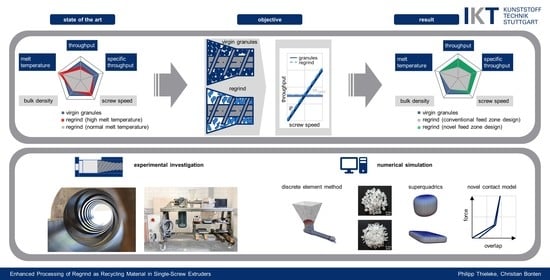
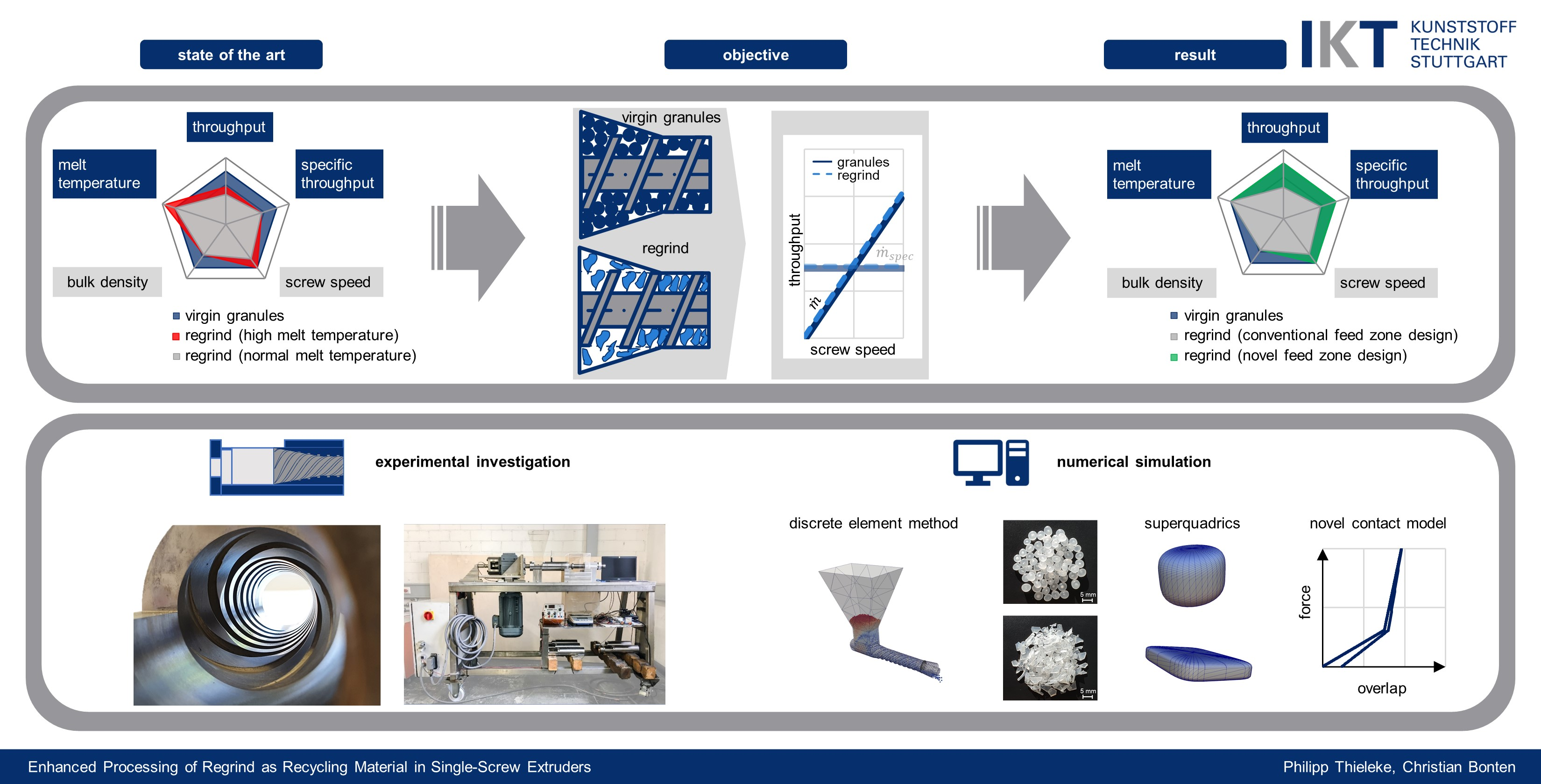
Enhanced Processing of Regrind as Recycling Material in Single-Screw Extruders

Institut für Kunststofftechnik, University of Stuttgart, 70569 Stuttgart, Germany
*
Author to whom correspondence should be addressed.
Polymers 2021, 13(10), 1540; https://doi.org/10.3390/polym13101540
Submission received: 29 March 2021
/
Revised: 22 April 2021
/
Accepted: 22 April 2021
/
Published: 11 May 2021
(This article belongs to the Special Issue Advances in Screw Processing of Polymeric Materials - In Memory of Professor James Lindsay White)
Abstract
:Regrind processing poses challenges for single-screw extruders due to the irregularly shaped particles. For grooved feed zones, the output is lessened by the reduction of bulk density in comparison to virgin material. Simultaneously, the melt temperature increases, reducing the extruder’s process window. Through experimental investigations on a test stand, a novel feed zone geometry (nominal diameter 35 mm) is developed. It aligns the regrind’s specific throughput with that of virgin material. The regrind processing window is essentially increased. As the solids conveying in the novel feed zone cannot be simulated with existing methods, numerical simulations using the discrete element method are performed. Since plastic deformation occurs in the novel feed zone geometry, a new hysteresis contact model is developed. In addition to spheres, the regrind and virgin particles are modeled as superquadrics to better approximate the irregular shape. The new contact model’s simulation results show excellent agreement with experimental compression tests. The throughput of the extruder simulations is considerably underestimated when using spheres to represent the real particles than when using irregularly shaped superquadrics. Corresponding advantages can be seen especially for virgin material.
1. Introduction
The recycling of plastics will grow considerably in the future. Thereby, the proportion of regrind material processed by single-screw extruders would equally increase. However, the irregular shape of the regrind particles in comparison to virgin material (see Figure 1) becomes a challenge for single-screw extruders.
When using grooved feed zone extruders, regrind material comprises a lower bulk density, resulting in a reduced specific throughput (throughput per screw revolution). This in turn decreases the extruder’s efficiency [1]. The extruder’s lower specific throughput leads to a higher melt temperature, which devalues the melt quality (Figure 2b, red area). The melt temperatures can be lowered by a reduced screw speed. (Figure 2b, gray area). This shows that regrind processing essentially reduces the extruder’s process window.
An improved feeding process of single-screw extruders has long been the goal of this research field. Hegele [3] examined eccentric filling zones where the granules could not be pushed back into the hopper section. This enhanced the solids conveying of the feed zone, which was also confirmed by further investigations by Potente et al. [4].
Recent work regarding asymmetric feed pockets was conducted by Michels [2] and Sikora [5,6]. However, eccentric filling zones are counterproductive for regrinding and reduce the specific throughput [2].
An optimized feed zone geometry for regrind processing can be found in so-called feed pockets. In the filling zone, the barrel’s inner diameter is larger than the nominal diameter. This provides the regrind material more space to flow into the extruder’s filling zone. However, it is recommended that the feed pocket’s design be kept small to prevent stagnation of material [2]. The influence of the angle from the feed pocket diameter to the nominal diameter was investigated by Krämer [7]. The flatter the angle, the higher the specific throughput.
Based on theoretical considerations, experimental investigations, and calculations carried out, Rahal [8] determined that a maximum effective flight depth must not be exceeded on the active screw flight, as otherwise the conveying efficiency would be negatively influenced. To maintain a sufficient screw channel volume, the screw channel is conical in an axial direction (see Figure 3).
Other research focused on adjustable means to influence the specific throughput of a single-screw extruder depending on the requirements. Behounek [9] developed a coaxial screw in which the feeding screw’s screw speed was independent of the plasticizing screw. In addition, special feed supports were developed, which are arranged separately from the plasticizing screw and can thus regulate the specific throughput [10]. Furthermore, attempts were made to influence the specific throughput with a variable groove geometry. Corresponding patents can be found in Kautz [11] and Peiffer [12]. However, the developments seen remained in prototype status and were not brought to market maturity [13].
There has been numerous research into calculating the solids conveying throughputs of single-screw extruders. It started with Peiffer’s [14] model of one-dimensional descriptions which was later refined by Kaczmarek [13]. Further essential one-dimensional models were developed by Grünschloß [15] and Schöppner [16]. Hennes [17] established the basis for the two-dimensional description of the throughput that was further developed into a three-dimensional one by Imhoff [18].
However, for an efficient three-dimensional consideration of solids conveying processes, the discrete element method (DEM) is used, in which the plastic granules are modeled as spheres. Cundall and Strack [19] developed the DEM in 1979 [20]. Newtonian laws of motion form the basis for the DEM, with particles having three translational and three rotational degrees of freedom. However, the particles are rigid and non-deformable. Therefore, simulation of processes with plastic deformation is challenging. Normal and tangential forces result from particle-particle collisions (see Figure 4). The selected contact law determines the normal and tangential forces, which comprise the spring stiffness k, the damping component c, and the friction µ (see Equations (1) and (2)) [21]. The new position of the particles can be calculated for a corresponding time step size [22]. Basis of the calculation is the virtual overlapping of the colliding particles [23].
Moysey and Thomson first used the discrete element method for three-dimensional simulations of a single-screw extruder’s feed zone [25]. Recirculation effects in the filling zone were detected, which had previously been determined in other investigations [26]. Further DEM applications were used to refine the boundary conditions and to optimize the feed zone geometry [27,28,29,30,31]. Other research proved that feed pockets are beneficial for the filling of the screw channel, which is relevant for regrind processing.
The particles of DEM simulation are generally represented as spheres (Figure 5a), although the real plastic granules are not ideally spherical. Other methods, such as multispheres (Figure 5b), allow for a better approximation of the real particle shape. One particle is made up of several other particles. Amberger et al. used this method in [32] for the approximation of non-convex and arbitrary objects. The disadvantage is a higher simulation time [22]. Finally, the particles can be approximated by superquadrics (Figure 5c). The shape is defined according to Formula (3) [20]. The shape of superquadrics results from a distortion of spheres and ellipsoids. The semi-axis lengths in x-, y-, and z-direction are defined by the parameters aSq, bSq, and cSq. The shape parameters nSq,1 and nSq,2 determine how angular the superquadric particle is shaped. Since there is only one particle, simulation time is reduced as compared to multispheres [20].
Leßmann and Schöppner [33] used the multisphere method to approximate the real shape of particles, which were cylinders and lenses (Figure 6). It was found that bulk density simulations comprising the approximation had an essential influence on the result. Leßmann used the examinations in [33] for further simulations of the feed zone with a smooth barrel in [34]. However, the output prediction did not improve. Further research on DEM simulations regarding solids conveying of single-screw extruders and particle shapes can be extracted from [35,36,37,38,39,40,41].
The spring and damper constants can be calculated according to Kloss [42]. The widely used fully elastic contact model is based on Hertz’s [43] work for the description of normal forces through a contact. Mindlin and Deresiewicz [44] extended Hertz’s model for the tangential force calculation. Additionally, the Hertz and Mindlin model is a non-linear elastic model as the spring and damper values are dependent on the particle overlap [42].
Unlike purely elastic models (Hertz), elastic-plastic models took into account the remaining deformation after unloading (Figure 7). The models of Thornton–Ning [44,45], VuQuoc–Zhang [46,47], Brake [48], and Walton and Braun [49,50,51] should be named in this context. Walton and Braun’s (Figure 7b) model consists of two different stiffnesses for the loading and unloading phases. The reduced stiffness for the relief phase leads to residual plastic deformation.
The objective of this work is to develop a feed zone geometry that achieves a complete alignment of the specific throughput when processing regrind. Thereby, the process window of the extrusion unit is significantly increased. The geometry should act passively and not influence the specific throughput through adjustable elements. This ensures an easy production-related realization of the feed zone geometry. Since such expected processes can no longer be described with analytical models, the DEM is used to perform solids conveying simulations.
Theorem 1.
In terms of compressibility and internal friction, the different bulk material properties of virgin granules and regrinds can be exploited by a compression zone in the single-screw extruder’s feed zone, achieving a full alignment of the specific throughput of virgin granules and regrinds without adjustable elements. This increases the process window for regrind processing in terms of throughput and melt temperature (see Figure 8).
The following experimental investigations, contact model developments, and results are part of the German Ph.D. thesis of Thieleke [52].
2. Methods and Experiments
Experimental Setup
The experimental investigations aim to examine different feed zone geometries cost-effectively. This is intended to determine the optimal feed zone geometry. For this purpose, a test stand is developed (similar to [53,54]) that only covers the barrel’s feed zone (Figure 9). The test stand was developed within the research project (see funding below, grant number ZF4041120CM7) together with the company Helix GmbH (Winnenden, Germany). The plastic is not molten within the test stand. With the mentioned test stand, it is possible to record the axial force of the screw in the direction of the gearbox.
The feed zone geometry of the single-screw extruder was developed based on the assumption that the compressibility and the internal friction of virgin granules and regrind are different. These different bulk properties will be used to align the specific throughput. Therefore, the bulk material must be compressed in the feed zone. The required compression ratio and the exact design of the compression zone are examined using different feed zone geometries. The following parameters of the feed zone geometry are varied (Figure 10).
- Diameter of filling zone DZ,max;
- Angle of compression zone φZ;
- Groove design of compression zone.
To evaluate the pressure level within the feed zone, two force sensors are applied in the compression zone (Figure 11). The forces and temperatures are originally recorded in a plasticizing barrel (see Thieleke [52]). The forces are recorded at two axial positions. Sensor 1 is positioned in the middle of the compression zone and sensor 2 at the end. The temperature is recorded at the same axial positions (Figure 11).
3. Materials
For the investigations, polyolefins from the material group high-density polyethylene (PE-HD) and polypropylene (PP) were chosen (Table 1). The selected PE-HD is Lupolen 4261AG UV60005, which is a product of the company Lyonell Basell, Rotterdam, Netherlands. The homopolymer DuPure G 72 TF from the company Ducor Petrochemicals, Rozenburg, Netherlands is used as PP. PE-HD is relevant for the blow molding of hollow parts. Blow molding involves an internal process regrind and is often returned to the process in a middle layer with a regrind share of 100%. Consideration of the PE-HD regrind is also essential for increasing recycling rates for blow-molded post-consumer containers in the future.
PP is increasingly used in flat film production and frequently replaces films that were previously made of polystyrene. Internal process regrind is also produced in flat film production and is returned to the extruder in the form of thin shreds.
A future range of applications regarding post-consumer articles may include thermoformed food trays. After usage, these thermoformed trays could be ground, washed, and added to the flat film process as regrind. Table 1 also shows the approximated shape of the particles for the implementation in the DEM simulation. To obtain these shapes, the particles were scanned (at least 200) to determine the particle size distribution. An optical analysis defined the shape parameter of the superquadrics nSQ,1 and nSQ,2 (roundness of the particle edges). By scanning the particles, the minimum and maximum ellipsoid diameters were determined using the Fiji software [52]. The weight of all particles and the density were used to calculate the average particle thickness [55].
Additionally, the equivalent sphere diameter was determined by measuring the particles’ volume of the superquadrics. The particle size distribution is applied to superquadrics and spheres (see results in Thieleke and Bonten [56]).
Furthermore, the materials were analyzed for bulk density according to Grünschloß [15] and compression tests (as shown in Figure 12) were conducted to determine its behavior under pressure and temperature (see [57]). An amount of 40 g of each material was inserted into the cup. The selected temperatures (23 °C, 61.5 °C, 100 °C) were set with the heater band. Before being filled, each material was heated up to the corresponding temperature in an oven. After filling, the compression die compacted the material to the chosen pressure levels of 50 bar, 100 bar, and 150 bar.
4. Numerical Simulation
The numerical simulation is carried out for the novel feed zone geometry, which aligns the regrind’s specific throughput to that of the virgin material (see Chapter 4. Results). The numerical simulations are performed using version 3.8.0 of the open-source DEM software LIGGGHTS® from DCS Computing GmbH in Linz, Austria. LIGGGHTS® is chosen as the source code since it can be adapted to allow for contact model adjustments. As large plastic deformation occurs in the compression zone, a new contact model is developed for the simulation of the novel feed zone geometry. Existing contact models are not able to realize such large plastic deformations.
For a better overview, some of the material properties that are ultimately used for the simulation are summarized in Table 2. These parameters are used for virgin and regrind material, as they are material properties not considered for their particle shape.
For the development of the novel contact model with plastic deformation, the hysteresis contact model of Walton and Braun [50,51] is selected as the basis. This consists of a linear loading phase and a linear unloading phase (cf. Figure 7b). Different slopes of the load and unload lines result in permanent deformation.
The experimental investigations on the tensile/compression testing machine are used to set up the contact model for the test materials PE-HD virgin, PE-HD regrind, PP virgin, and PP regrind. The deformation behavior is considered dependent on pressure and temperature.
The pure linearization of Walton and Braun’s contact model results in a poor fit of the bulk material compression for small forces. In addition, the deformation turns out to be too small for large forces. For this reason, a two-stage hysteresis contact model is selected for the loading and unloading phases (Figure 13a). The compression test of PE-HD virgin material is used to explain the determination. It is carried out equivalently for the remaining three bulk materials.
Two straight lines (g1 and g2) define the load curve of the compression test of PE-HD (Figure 13, red curve) up to a maximum force of 20,000 N. The intersection point P12 is on the load curve. With numerical approximation, the integral of the two straight lines g1 and g2 with the load curve is minimized. Another boundary for the numerical approximation is that both integrals of g1 and g2 with the experimental load curve are equal. This results in P12.
A third straight line (g3), which passes through the intersection point P12 and the point P3, is defined. P3 is described by the density and the volume obtained from the pvT measurement on the respective material at a defined temperature ϑ2 measured in the compression zone (see measurement of temperature 2 in Figure 11). The pressure of the pvT curve was 300 bar. Thus, P3 denotes an assumed compacted solid bed and represents a maximum bulk density.
In the loading phase, the two-stage model is formed starting from the straight line g1 up to the intersection point P12 with the stiffness K11, while the straight line g3 begins from the intersection point P12 up to the point P3 with the stiffness K12. This is used to calculate correct forces for small overlaps δn. For large particle overlaps, the second stage prevents the forces from remaining very small.
For the unloading stage, Walton and Braun’s model is followed. The relation of the coefficient of restitution is used to measure the change in stiffness. This results in the straight line g4 with stiffness K21. At the same y-value as point P12, the second unloading curve starts with another stiffness (g5). In comparison to stiffness K12, stiffness K22 is also determined via the coefficient of restitution.
The linear equations are established using the experimental compression of the bulk. However, the contact model defines the force/deformation curve for a single particle. For this reason, the intersection point P12 is iteratively shifted horizontally (P12,new) until the resulting load curve from the numerical simulation of the bulk compression considerably agrees with the experiment’s reference curve (Figure 13b).
The ratio of the stiffnesses K11 and K12 is kept constant during the iteration. Due to the simulation time, the iterations are performed solely for modeling the particles as spheres. The obtained contact models for the particular bulk material are used for superquadrics as well. The iteration starting values and the selected stiffnesses are listed in Appendix B (Table A1).
Validation of the Numerical Simulation
The simulative determination of the bulk density will show if the particle shapes lead to a realistic match. The experimental bulk density measurements serve as a reference. The bulk density simulations are performed in the same way as the DIN EN ISO 60 [58] test. The measuring cup with a depth of 51 mm is filled with granules until it is full. A wiper strips off the protruding particles (Figure 14a).
After the stripping process, the mass of the particles in the measuring cup is determined. The mass divided by the volume results in the bulk density. The simulations are performed with spheres and superquadrics for virgin material and regrind, respectively. After the particle bulk density simulations, the compression test simulations are conducted. The developed contact models are used for each material. The bulk material is compacted to a maximum force of 20,000 N (approximately 138 bar). The pressure is set by the movable pressure plate, which is force-controlled by a servo command (Figure 14b). In contrast to the experiment, the influence of temperature is passively considered by the developed contact model.
The simulation of the single-screw extruder solely considers the solids conveying in the feed zone. It is comparable to the experimental investigation on the test stand. The components have meshed using the meshing software Salome from Open Cascade SAS. The screw and barrel meshing level of detail is set to a maximum element size of 7 mm. The hopper was coarsely meshed. Salome generates a triangle-based surface model in STL format (Figure 15).
In each case, the simulation time is 19.2 s in real-time to obtain a steady state and be able to make reliable statements. In simulative preliminary investigations, it was determined that the selected simulation time is sufficient for a constant throughput.
5. Results
The results are divided into two categories: test stand experimental results and DEM simulation results.
5.1. Experimental Results of the Feed Zone Geometry Variation
The trials run on the test stand with a grooved and smooth compression zone reveal that the feed zone’s conical area must be grooved to ensure adequate solids conveying (Figure 16). For PE-HD, no conveying takes place when the compression zone is smooth. For PP, an unstable output was observed when the compression zone is without grooves.
A comparison of the compression zone’s angle variation is shown in Figure 17. The diameter of the filling zone was kept constant at DZ,max = 50 mm. The chart demonstrates that the angle can be used to influence the throughput. A flatter angle increases the throughput. Trials with an angle of 5° achieved an even higher output. However, since the results could not be taken for every material, the data were excluded. These findings already illustrate that a 10° angle can be used to achieve an alignment of the specific throughputs. That alignment of the specific throughputs of regrind and virgin material with a grooved compression zone is also shown in Figure 16 for DZ,max = 50 mm and φZ = 10°.
Further comparisons of the filling diameter indicate that a compression zone can influence the difference in throughput between regrind and virgin material. DZ,max = 38 mm represents a standard feed zone with a difference of 37% (Figure 18). A larger filling diameter reduces the throughput difference. At DZ,max = 50 mm, the throughputs are almost equal. In contrast to virgin material (DZ,max = 65 mm), a larger diameter leads to an even higher throughput of regrind.
Proof of Theorem 1.
With these findings, the aforementioned theorem is proven. With a new type of compression zone in the feed zone, the different bulk material properties of virgin granules and regrind material, in terms of internal friction and compressibility, are exploited to achieve a complete alignment of the specific throughput within a compression zone. □
For the considered PE-HD and PP bulk materials, the optimum feed zone geometry with a nominal diameter of 35 mm includes a grooved compression zone, a filling diameter of DZ,max = 50 mm, and an angle of φZ = 10°.
The pressure and temperature measurements in the novel feed zone geometry are decisive for the DEM’s new contact model. The pressure level is evaluated by the axial force measurement and temperature measurements at the test stand. Additionally, the measurement setup in Figure 11 is used to determine the precise force and temperature measurements.
To obtain the axial pressure from the radial pressure, the pressure anisotropy k must be considered for bulk solids. According to [2,59,60], kvirgin = 0.5 is chosen for the moving bulk material consisting of virgin material. Since the pressure anisotropy coefficient k for regrind is larger than for virgin material, kregrind = 0.55 is determined for the regrind [2]. From the measurement of the radial force, the radial pressure at position 2 can be calculated using the cross-section of the force application pin and the respective anisotropy coefficient (Figure 19a). In addition, Figure 19b shows the measured temperature at position 2. The results of the pressure and temperature measurements depict quite similar tendencies.
5.2. Result of the Validation of the Numerical Simulation
5.2.1. Bulk Density Simulation
The numerical determination of the bulk density reflects how well the approximation with spheres and superquadrics achieved the real particle shape of the virgin granules and the regrinds. For this purpose, Figure 20 compares the results of the experiment and simulation. It can be seen that spheres are better suited to represent the real bulk density in the case of virgin granules. The deviation is less than 1%. With the superquadrics’ more accurate approximation of the real particle shape, the bulk density for PE-HD and PP is slightly overestimated.
The simulative determination of the bulk density of regrind remains a challenge. The bulk density of spheres and superquadrics is significantly overestimated. However, superquadrics reduce the discrepancy between experiment and numerical simulation. Superquadrics achieve better results due to the platelet shape. However, all superquadric regrind particles are platelet-shaped in the simulation environment. In reality, these are rather irregularly shaped, making them more likely to interlock and create hollow spaces between particles. In the future, different shapes of regrind particles may be included to achieve enhanced results for superquadrics, especially for regrind.
In terms of bulk density simulation, spheres can be recommended for virgin granules. For regrind materials, the approximation of the particle shape with superquadrics leads to better results.
5.2.2. Compression Test Simulation
The developed contact model is checked for suitability through the compression test simulations. A comparison of different state-of-the-art contact models is made (Figure 21). The newly developed elastic-plastic contact model is compared to those of Hertz and Walton and Braun.
Figure 21a shows the force/deformation curve for the compression of a single sphere with a diameter of 45 mm. These results are used to describe the deformation behavior of a single particle, which defines the respective contact model. In Figure 21b, the force/deformation curve is plotted for the compression of the bulk virgin material of PE-HD. In this case, the particles are defined as spheres.
If Hertz’s (red) purely elastic contact model is used, the simulated force/deformation curve of the single sphere is identical to the load and unload curve. The particles’ rearrangement effects produce a hysteresis curve. However, there is no remaining deformation, and the load and unload curves are much steeper compared to the other models.
This results in a poor approximation to the experimentally determined curve (dark blue curve) in Figure 21b. The poor agreement is due to the model’s purely elastic behavior, with no representation of plastic deformation. As a result, the model is extremely stiff. An increasing force results in deformations that are too small compared to reality. Furthermore, the temperature is not considered. The experimental curve (dark blue) of PE-HD represents a temperature of 73 °C.
When using Walton and Braun’s (orange) elastic-plastic contact model, the different stiffnesses for loading and unloading result in a residual deformation. It shows small deformations for small forces and extremely large deformations for larger forces. The approximation to the experiment is also not successful with this model.
The two-stage approach of Walton and Braun’s (gray) hysteresis model, which was developed here, yields an excellent agreement with the obtained experimental curve. Due to the two-stage loading phase, the deformation course of the bulk material can be efficiently reproduced. Furthermore, the temperature influence can be optimally considered.
The additionally simulated force/deformation curves for PE-HD and PP in comparison to the experimental curves are shown in Appendix A (Figure A1). In comparison to virgin material, a larger deviation can be observed for regrind. The reason for this is that the model cannot be set arbitrarily soft, and the determined curves must be considered optimum for a stable numerical calculation.
5.2.3. Extruder Simulations
The results of the extruder simulations are summarized in Figure 22. It shows the specific throughput of PE-HD and PP for virgin and regrind at a screw speed of 100 min−1. The simulations were performed with spheres and superquadrics, using the newly developed contact model with two-stage loading and two-stage unloading phases.
It appears that the specific throughput is generally underestimated. When spheres are used, the deviation is significantly larger than with superquadrics. In the case of PE-HD virgin material, for example, although the bulk density is optimally represented by spheres and the compression curve highly corresponds to the compression experiment curve, the numerical extruder simulation reflects a deviation of 26.8%. In the simulation, the particles in the compression zone are assumed to slide away from each other. Therefore, fewer particles are conveyed into the compression zone and ultimately compressed.
The specific throughput for PE-HD virgin material simulated with superquadrics depicts a deviation of 15.1%. The non-spherical shape probably prevents early slippage between the particles in the compression zone.
It is particularly apparent that superquadrics reproduce the alignment of the specific throughput for virgin and regrind material, which was also obtained in the experiment. This result is valid for PE-HD and PP.
In summary, numerical simulation with DEM generally under-predicts the throughputs of the novel feed zone geometry. Since the bulk density and contact model achieve outstanding agreements with the compression simulation, especially for the virgin granules, it can be assumed that either the remaining deformation (after plastic deformation) or the conveying in the compression zone is not yet completely and realistically represented.
Concerning the conveying behavior of the bulk materials, further experimental investigations on flowing bulk materials could help to optimize the throughput in the numerical simulation. Particularly for regrind approximated by superquadrics, the actual bulk density in the moving state could differ significantly from the static measurements, since the platelet-shaped particles would form more hollow spaces between each other. This would compensate for the discrepancy between experimentally and simulatively determined bulk density in the static case. The work of Hennes [17], which investigates the pressure anisotropy on moving bulk solids, could serve as a model for future research on moving bulk solids in terms of bulk density and conveying behavior.
According to Walton and Braun’s new hysteresis model, a remaining deformation is not stored after complete unloading. Consequently, if a new contact arises, the loading starts again from the beginning. This will probably have the greatest influence on the discrepancy between experiment and simulation throughputs. Another approach pursued by DCS Computing GmbH, Linz, Austria, and the team of Christoph Kloss [61,62] is to reduce a particle’s diameter after plastic deformation. Thus, each particle’s remaining deformation is stored. However, this method is currently reserved for the premium version of LIGGGHTS® and is not implemented in the open-source version. It is expected that this approach will reduce the current gap between experimentally and simulatively determined throughputs.
Furthermore, pressure and temperature rise in the compression zone. So far, a constant value is used for the temperature, which is reflected in the contact model. In further investigations, the resulting frictional heat could also be calculated to better implement the temperature in the simulation. In line with this approach, reference can be made to Trippe’s research [24].
6. Conclusions and Outlook
The investigations reveal the relevance of regrind processing in single-screw extrusion. A novel feed zone geometry allows for the complete alignment of the specific throughput of regrind and virgin material. It is achieved using an extruder with a nominal screw diameter of 35 mm without adjustable elements. For this purpose, a new type of compression zone is used in the feed zone of the extruder. Through experimental investigations on a specially developed test stand, it was possible to determine the optimum feed zone geometry with regard to the diameter of the filling zone DZ,max, the groove design, and the angle φZ of the compression zone.
In contrast to the respective virgin material, a complete alignment of the specific throughput is achieved for both PE-HD and PP regrind. The increased specific throughput simultaneously increases the absolute throughput. It substantially expands the regrind processing process window as summarized in Figure 23. The new process window for regrind is defined by the green area.
Superquadrics, rather than pure spheres, can better represent the real particle shape of regrind in numerical simulations through DEM. This shows advantages in reference to bulk density measurements and extruder throughput measurements. Based on compression tests on real bulk materials, a new hysteresis contact model is set up for the DEM following the approach of Walton and Braun. A two-stage loading and two-stage unloading process are included in the model. Compression tests with temperature influence were used to calibrate the model, which accurately represents plastic deformation. When using the new contact model for the extruder simulations, the throughputs are generally underpredicted.
To improve the predicted throughput by numerical simulation using DEM, the particles’ remaining deformation through plastic deformation could be performed using a particle radius reduction. This approach is already implemented by DCS Computing GmbH, Linz, Austria, and the team of Christoph Kloss in the premium version of LIGGGHTS®.
The investigations relate to an extruder size of d = 35 mm. Larger diameters should be examined to transfer the findings of this work. Additionally, a temperature-dependent contact model for the numerical simulation would be beneficial. Ideally, the temperature in the DEM will be calculated through dissipation between the particles rather than indirectly by the contact model. Trippe’s investigations [24] may be helpful in this regard.
Author Contributions
Conceptualization, P.T.; methodology, P.T.; software, P.T.; validation, P.T.; formal analysis, P.T.; investigation, P.T.; writing—original draft preparation, P.T.; writing—review and editing, P.T., C.B.; visualization, P.T.; supervision, C.B. All authors have read and agreed to the published version of the manuscript.
Funding
This research was funded by the AiF ZIM (Central Innovation Program for Small and Medium-Sized Enterprises) with grant number ZF4041120CM7.
Institutional Review Board Statement
Not applicable.
Informed Consent Statement
Not applicable.
Data Availability Statement
Not applicable.
Acknowledgments
Special thanks go to Helix (Winnenden, Germany) for the extensive cooperation during the research project.
Conflicts of Interest
The authors declare no conflict of interest.
Appendix A
Figure A1.
Comparison between experimental and simulation data of the compression test.

Appendix B

Table A1.
Material parameters for the numerical simulation.
| PE-HD Virgin | PE-HD Regrind | PP Virgin | PP Regrind | |
|---|---|---|---|---|
| P12,start | 11.04/6182 | 18.64/4141 | 7.32/5625 | 16.68/5099 |
| P3 | 20.20/47,713 | 28.13/47,713 | 20.40/47,713 | 31.40/47,713 |
| P12,new | 7.54/6182 | 16.96/4141 | 6.59/5625 | 19.66/5099 |
| K11 | 0.62 | 0.32 | 0.72 | 9.16 |
| K12 | 8.09 | 20.67 | 4.19 | 0.24 |
| K21 | 10.68 | 27.28 | 6.37 | 0.36 |
| K22 | 0.82 | 0.42 | 1.10 | 13.92 |
References
- Bonten, C. Plastics Technology–Introduction and Fundamentals; Hanser Publisher: Munich, Germany, 2019; ISBN 979-1-56990-767-2. [Google Scholar]
- Michels, R. Improving the Processing Range and Performance of Single-Screw Extruders. Ph.D. Thesis, Universität Duisburg-Essen, Fachbereich Ingenieurwissenschaften, Abteilung Maschinenbau, Duisburg, Germany, 2005. [Google Scholar]
- Hegele, R. Investigation of the Processing of Powdered Polyolefins on Single-Screw Extruders. Ph.D. Thesis, RWTH Aachen, Fakultät für Maschinenwesen, Aachen, Germany, 1972. [Google Scholar]
- Potente, H.; Pohl, T.C. Simulation and analyses of the polymer-pellet-flow into the first section of a single screw. In Proceedings of the Annual Technical Conference (SPE ANTEC), Dallas, TX, USA, 6–10 May 2001; Society of Plastics Engineers: Danbury, CT, USA, 2001. [Google Scholar]
- Sikora, J.W. Feeding an extruder of a modified feed zone design with poly(vinyl chloride) pellets of variable geometric properties. Int. Polym. Process. 2014, 29, 412–418. [Google Scholar] [CrossRef]
- Sikora, J.W.; Samujlo, B. Investigation of the poly(vinyl chloride) extrusion process using a feed throat with a feed pocket. Polym. Eng. Sci. 2014, 54, 2037–2045. [Google Scholar] [CrossRef]
- Krämer, A. Practical experience in the use of single-screw extruders with grooved feed zone. Kunststoffe 1988, 78, 21–26. [Google Scholar]
- Rahal, H. Alternative Methods for Solids Conveying and Plasticizing in Extrusion Technology. Ph.D. Thesis, Universität Duisburg-Essen, Fachbereich Ingenieurwissenschaften, Abteilung Maschinenbau, Duisburg, Germany, 2008. [Google Scholar]
- Behounek, G. Extruder. DE Patent No. DE4406372C1, 23 February 1995. [Google Scholar]
- Buchheit, D. Screw Extruder for Plasticizable Materials Especially for Processing Powdery Material. DE Patent No. DE2060706B, 10 December 1970. [Google Scholar]
- Kautz, G.; Schumacher, F.; Hagen, K.-H. Screw Extruder for Processing Thermoplastic and/or Thermosetting Compounds. DE Patent No. DE 3233841, 11 September 1982. [Google Scholar]
- Peiffer, H.; Eberhardt, H. Screw Extruder. U.S. Patent Application No. US4678339, 7 July 1987. [Google Scholar]
- Kaczmarek, D. Solids Conveying and Alternative Plasticizing during Extrusion. Ph.D. Thesis, Universität Duisburg-Essen, Fachbereich Ingenieurwissenschaften, Abteilung Maschinenbau, Duisburg, Germany, 2004. [Google Scholar]
- Peiffer, H. Contribution to the Conveying Problem in the Grooved Feed Zone of Single-Screw Extruders. Ph.D. Thesis, Rheinisch-Westfälische Technische Hochschule (RWTH), Fakultät für Maschinenwesen, Aachen, Germany, 1981. [Google Scholar]
- Grünschloß, E. Bulk density and mass throughput in grooved barrel extruders. Kunststoffe 1993, 83, 309–311. [Google Scholar]
- Schöppner, V. Simulation of the Plasticizing Unit of Single-Screw Extruders. Ph.D. Thesis, Universität Paderborn, Fakultät für Maschinenbau, Paderborn, Germany, 1995. [Google Scholar]
- Hennes, J. Determination of Material Indices of Plastic Bulk Materials and Simulation of the Processes in the Feed Section of Conventional Single-Screw Extruders. Ph.D. Thesis, RWTH Aachen, Fakultät für Maschinenwesen, Aachen, Germany, 2000. [Google Scholar]
- Imhoff, A. Three-Dimensional Description of the Processes in a Single-Screw Plasticizing Extruder. Ph.D. Thesis, RWTH Aachen, Fakultät für Maschinenwesen, Aachen, Germany, 2004. [Google Scholar]
- Cundall, P.A.; Strack, O.D.L. A discrete numerical model for granular assemblies. Géotechnique 1979, 29, 47–65. [Google Scholar] [CrossRef]
- Podlozhnyuk, A.; Pirker, S.; Kloss, C. Efficient implementation of superquadric particles in Discrete Element Method within an open-source framework. Comput. Part. Mech. 2017, 4, 101–118. [Google Scholar] [CrossRef] [Green Version]
- Kloss, C.; Goniva, C.; Hager, A.; Amberger, S.; Pirker, S. Models, algorithms and validation for opensource DEM and CFD-DEM. PCFD 2012, 12, 140–152. [Google Scholar] [CrossRef]
- Jakob, C.; Konietzky, H. Particle Methods. An Overview; Manuscript of the Technical University Bergakademie Freiberg; Technical University Bergakademie: Freiberg, Germany, 2012; pp. 1–23. [Google Scholar]
- Trippe, J.; Schöppner, V. Investigation of the influence of material and pellet shape on the dissipation in the solids conveying zone of single-screw extruders based on the discrete element method (DEM). In Proceedings of the 32nd International Conference of the PPS, Lyon, France, 25–29 July 2016; Volume 32, p. 080002. [Google Scholar] [CrossRef] [Green Version]
- Trippe, J. Extension of Modeling the Throughput and Performance Calculation of Solids Conveying Processes in Single-Screw Extrusion. Ph.D. Thesis, Universität Paderborn, Fakultät für Maschinenbau, Paderborn, Germany, 2018. [Google Scholar]
- Moysey, P.A.; Thompson, M.R. Investigation of solids transport in a single-screw extruder using a 3D discrete particle simulation. Polym. Eng. Sci. 2004, 44, 2203–2215. [Google Scholar] [CrossRef]
- Celik, O.; Bonten, C. Three-Dimensional simulation of a single-screw extruder’s grooved feed section. In Proceedings of the AIP Conference Proceedings 1779 (PPS2015), Graz, Austria, 21–25 September 2016; American Institute of Physics: College Park, MD, USA, 2016. [Google Scholar]
- Moysey, P.A.; Thompson, M.R. Modelling the solids inflow and solids conveying of single-screw extruders using the discrete element method. Powder Technol. 2005, 153, 95–107. [Google Scholar] [CrossRef]
- Moysey, P.A.; Thompson, M.R. Discrete particle simulations of solids compaction and conveying in a single-screw extruder. Polym. Eng. Sci. 2008, 23, 62–73. [Google Scholar] [CrossRef]
- Pape, J.; Hörmann, H.; Weddige, R. New screw concepts for increased performance. In Proceedings of the VDI Fachtagung, “Hochleistungsextrusion und Betriebskostenoptimierung”, Bonn, Germany, 16–17 June 2010; pp. 125–142. [Google Scholar]
- Schöppner, V.; Weddige, R. Improving the feeding zone of single screw extruders at high rotation speed by using the discrete element method. In Proceedings of the Annual Technical Conference (SPE ANTEC), Orlando, FL, USA, 16–20 May 2010; Society of Plastics Engineers: Danbury, CT, USA, 2010; Volume 68, pp. 610–616. [Google Scholar]
- Leßmann, J.S.; Weddige, R.; Schöppner, V.; Porsch, A. Modelling the solids throughput of single screw smooth barrel extruders as a function of the feed section parameters. Int. Polym. Proc. 2012, 27, 469–477. [Google Scholar] [CrossRef]
- Amberger, S.; Friedl, M.; Goniva, C.; Pirker, S.; Kloss, C. Approximation of objects by spheres for multisphere simulations in DEM. In Proceedings of the European Congress on Computational Methods in Applied Sciences and Engineering, Vienna, Austria, 10–14 September 2012. [Google Scholar]
- Leßmann, J.-S.; Schöppner, V. Validation of discrete element simulations in the field of solids conveying in single-screw extruders. In Proceedings of the 30th International Conference of the Polymer Processing Society (PPS-30), Cleveland, OH, USA, 6–12 June 2014. [Google Scholar]
- Leßmann, J.-S. Calculation and Simulation of Solids Conveying Processes in Single-Screw Extruders Up to the High-Speed Range. Ph.D. Thesis, Universität Paderborn, Fakultät für Maschinenbau, Paderborn, Germany, 2016. [Google Scholar]
- Trippe, J.; Schöppner, V. Modeling of solid conveying pressure throughput behavior of single screw smooth barrel extruders under consideration of backpressure and high screw speeds. Int. Polym. Process. 2018, 33, 486–496. [Google Scholar] [CrossRef]
- Trippe, J.; Schöppner, V. Modeling of the dissipation in the solid conveying section in single screw extruders. In Proceedings of the 34th International Conference of the Polymer Processing Society (PPS-34), Taipei, Taiwan, 21–25 May 2018; p. 030036. [Google Scholar] [CrossRef]
- Schoeppner, V.; Bruening, F. Development of a solids conveying throughput model for grooved barrel extruders based on discrete element simulations. In Advances in Polymer Processing; Hopmann, C., Dahlmann, R., Eds.; Springer: Berlin/Heidelberg, Germany, 2020; pp. 50–62. [Google Scholar] [CrossRef]
- Soltanbeigi, B.; Podlozhnyuk, A.; Ooi, J.Y.; Kloss, C.; Papanicolopulos, S.-A. Comparison of multi-sphere and superquadric particle representation for modelling shearing and flow characteristics of granular assemblies. EPJ Web Conf. 2017, 140. [Google Scholar] [CrossRef] [Green Version]
- Soltanbeigi, B.; Podlozhnyuk, A.; Papanicolopulos, S.-A.; Kloss, C.; Pirker, S.; Ooi, J.Y. DEM study of mechanical characteristics of multi-spherical and superquadric particles at micro and macro scales. Powder Technol. 2018, 329, 288–303. [Google Scholar] [CrossRef] [Green Version]
- Kildashti, K.; Dong, K.; Samali, B. A revisit of common normal method for discrete modelling of non-spherical particles. Powder Technol. 2018, 326, 1–6. [Google Scholar] [CrossRef]
- Zhu, H.P.; Zhou, Z.Y.; Yang, R.Y.; Yu, A.B. Discrete particle simulation of particulate systems: Theoretical developments. Chem. Eng. Sci. 2007, 62, 3378–3396. [Google Scholar] [CrossRef]
- Kloss, C. LIGGGHTS-PUBLIC Documentation; DCS Computing Gmbh: Linz, Austria, 2016. [Google Scholar]
- Hertz, H. About the contact of solid elastic bodies. J. Reine Angew. Math. 1881, 92, 156–171. [Google Scholar]
- Thornton, C.; Ning, Z. A theoretical model for the stick/bounce behaviour of adhesive, elastic-plastic spheres. Powder Technol. 1998, 99, 154–162. [Google Scholar]
- Thornton, C. Granular dynamics, contact mechanics and particle system simulations. Part. Technol. Ser. 2015, 24. [Google Scholar] [CrossRef]
- Vu-Quoc, L.; Zhang, X. An elastoplastic contact force–displacement model in the normal direction: Displacement–driven version. Proc. R. Soc. Lond. A 1999, 455, 4013–4044. [Google Scholar] [CrossRef]
- Vu-Quoc, L.; Zhang, X.; Lesburg, L. Normal and tangential force-displacement relations for frictional elasto-plastic contact of spheres. Int. J. Solids Struct. 2001, 38, 6455–6489. [Google Scholar] [CrossRef]
- Brake, M.R. An analytical elastic-perfectly plastic contact model. Int. J. Solids Struct. 2012, 49, 3129–3141. [Google Scholar] [CrossRef] [Green Version]
- Walton, O.R.; Braun, R.L. Stress calculations for assemblies of inelastic speres in uniform shear. Acta Mech. 1986, 63, 73–86. [Google Scholar] [CrossRef]
- Walton, O.R. Chapter 25: Numerical Simualtion of Inelastic, Frictional Particle-Particle Interactions. In Particulate Two Phase Flow; Cambridge University Press: Cambridge, UK, 1993; Volume 25, pp. 884–911. [Google Scholar]
- Walton, O.R. (Linearized) Elastic-Plastic Contact Model; DEM Solutions: Edinburgh, UK, 2006. [Google Scholar]
- Thieleke, P. Increasing the Process Window of Single-Screw Extruders Operated with Regrind as Recycling Material. Ph.D. Thesis, Universität Stuttgart, Fakultät für Energie-, Verfahrens- und Biotechnik, Stuttgart, Germany, 2020. [Google Scholar]
- Hyun, K.S.; Spalding, M.A.; Hinton, C.E. Theoretical and experimental analysis of solids conveying in single-screw extruders. J. Reinf. Plast. Compos. 1997, 16, 1210–1216. [Google Scholar] [CrossRef]
- Leßmann, J.-S.; Schoeppner, V. Discrete element simulations and validation tests investigating solids-conveying processes with pressure buildup in single screw extruders. In Proceedings of the 31st International Conference of the Polymer Processing Society (PPS-31), Jeju Island, Korea, 7 June 2015; Volume 31, p. 110003. [Google Scholar] [CrossRef]
- Jaklič, A.; Leonardis, A.; Solina, F. Segmentation and recovery of superquadrics. Comput. Imaging Vis. 2000, 20. [Google Scholar] [CrossRef]
- Thieleke, P.; Bonten, C. Increasing the process window of single-screw extruders operated with regrind. In Proceedings of the Annual Technical Conference (SPE ANTEC 2020), Online, 30 March–5 May 2020; Society of Plastics Engineers: Danbury, CT, USA, 2020. [Google Scholar]
- Maaßen, R. Construction and Testing of a Device for Measuring the Bulk Density of Plastic Particle. Bachelor’s thesis, University of Stuttgart, Institut für Kunststofftechnik, Stuttgart, Germany, 2015. [Google Scholar]
- Deutsches Institut für Normung e. V. Kunststoffe. Determination of the Apparent Density of Molding Compounds that can Flow Through a Standardized Funnel (Bulk Density); ISO 60:1977; Deutsche Fassung EN ISO 60:1999; Beuth Verlag: Berlin, Germany, 2000. [Google Scholar] [CrossRef]
- Schneider, K. The influence of the feed zone on the conveying characteristics of a single-screw extruder. Kunststoffe 1969, 59, 757–760. [Google Scholar]
- Raschka, K. Determination of the flow Properties of Moist Bulk Solids with Application to Screw Extrusion. Ph.D. Thesis, Universität Karlsruhe, Karlsruhe, Germany, 1990. [Google Scholar]
- Kloss, C.; Aigner, A.; Mayrhofer, A. LIGGGHTS® Short Course CFDEM Research; Part 1; DCS Computing Gmbh: Linz, Austria, 2014. [Google Scholar]
- Kloss, C.; Aigner, A.; Mayrhofer, A. LIGGGHTS® Short Course CFDEM Research; Part 2; DCS Computing Gmbh: Linz, Austria, 2014. [Google Scholar]
Figure 1.
(a) Regrind material; (b) virgin material granules.

Figure 2.
(a) Influence of an increased regrind share adapted with permission from [2]. 2021 Michels; (b) reduced process window through regrind processing.
Figure 2.
(a) Influence of an increased regrind share adapted with permission from [2]. 2021 Michels; (b) reduced process window through regrind processing.

Figure 3.
Conical screw channel for improved conveying adapted with permission from [8]. 2021 Rahal.
Figure 3.
Conical screw channel for improved conveying adapted with permission from [8]. 2021 Rahal.

Figure 4.
Contact forces at particle collision adapted with permission from [24]. 2021 Trippe.
Figure 4.
Contact forces at particle collision adapted with permission from [24]. 2021 Trippe.

Figure 5.
Representation of particle shapes in simulation environment (a) sphere; (b) multisphere; (c) superquadric.
Figure 5.
Representation of particle shapes in simulation environment (a) sphere; (b) multisphere; (c) superquadric.

Figure 6.
Transfer of the (a) real granule shape into (b) 3D simulation adapted with permission from [24]. 2021 Trippe.
Figure 6.
Transfer of the (a) real granule shape into (b) 3D simulation adapted with permission from [24]. 2021 Trippe.

Figure 7.
(a) Remaining plastic deformation after load adapted with permission from [46]. 2021 Vu-Quoc; (b) Contact model of Walton and Braun adapted with permission from [24]. 2021 Trippe.

Figure 8.
Visualization of the theorem.

Figure 9.
(a) Experimental setup; (b) sectional view of the test stand.

Figure 10.
Variation of geometry parameters of the feed zone.

Figure 11.
Radial force and temperature measurements at the feed zone.

Figure 12.
Compression test with a tensile/compression testing machine.

Figure 13.
Contact model development. (a) starting point (b) shift.

Figure 14.
Simulation setup for the (a) bulk density; (b) compression behavior.

Figure 15.
Simulation setup to determine the solids conveying.

Figure 16.
Experimental throughput depending on grooves in the compression zone.

Figure 17.
Experimental throughput depending on the angle of the compression zone.

Figure 18.
Experimental throughput depending on diameter extension filling zone.

Figure 19.
(a) Radial and axial forces and (b) temperatures in the feed zone.

Figure 20.
Bulk density comparison between experiment and simulation.

Figure 21.
(a) General compression behavior of the contact models for one sphere; (b) compression behavior of the contact models for the bulk according to a compression test.
Figure 21.
(a) General compression behavior of the contact models for one sphere; (b) compression behavior of the contact models for the bulk according to a compression test.

Figure 22.
Mass throughput comparison between experiment and simulation.

Figure 23.
Increased process window for the processing of regrind material.

Table 1.
Overview of applied materials and particle geometry transformation in the numerical simulation environment.
Table 1.
Overview of applied materials and particle geometry transformation in the numerical simulation environment.
| PE-HD Virgin | PE-HD Regrind | PP Virgin | PP Regrind |
|---|---|---|---|
 |  |  |  |
superquadric | superquadric | superquadric | superquadric |
sphere | sphere | sphere | sphere |
Table 2.
Material parameters for the numerical simulation.
| Simulation Parameter | PE-HD | PP |
|---|---|---|
| density in g/cm³ | 0.945 1 | 0.91 1 |
| Young’s modulus in MPa | 850 1 | 1850 1 |
| Poisson’s ratio | 0.443 2 | 0.399 2 |
| internal coefficient of restitution | 0.87 2 | 0.81 2 |
| external coefficient of restitution | 0.83 2 | 0.85 2 |
| internal friction | 0.498 2 | 0.432 2 |
| external friction | 0.303 2 | 0.304 2 |
1 from data sheet, 2 determined in Thieleke [52].
Publisher’s Note: MDPI stays neutral with regard to jurisdictional claims in published maps and institutional affiliations. |
© 2021 by the authors. Licensee MDPI, Basel, Switzerland. This article is an open access article distributed under the terms and conditions of the Creative Commons Attribution (CC BY) license (https://creativecommons.org/licenses/by/4.0/).
Share and Cite
MDPI and ACS Style
Thieleke, P.; Bonten, C. Enhanced Processing of Regrind as Recycling Material in Single-Screw Extruders. Polymers 2021, 13, 1540. https://doi.org/10.3390/polym13101540
AMA Style
Thieleke P, Bonten C. Enhanced Processing of Regrind as Recycling Material in Single-Screw Extruders. Polymers. 2021; 13(10):1540. https://doi.org/10.3390/polym13101540
Chicago/Turabian StyleThieleke, Philipp, and Christian Bonten. 2021. "Enhanced Processing of Regrind as Recycling Material in Single-Screw Extruders" Polymers 13, no. 10: 1540. https://doi.org/10.3390/polym13101540
Note that from the first issue of 2016, this journal uses article numbers instead of page numbers. See further details here.