Article

An Air-Ground Wireless Sensor Network for Crop Monitoring

CAR UPM-CSIC, C/Jose Gutierrez Abascal, 2, 28006 Madrid, Spain
*
Author to whom correspondence should be addressed.
Sensors 2011, 11(6), 6088-6108; https://doi.org/10.3390/s110606088
Submission received: 21 March 2011 / Revised: 25 May 2011 / Accepted: 30 May 2011 / Published: 7 June 2011
(This article belongs to the Special Issue Sensors in Agriculture and Forestry)

Abstract

:
This paper presents a collaborative system made up of a Wireless Sensor Network (WSN) and an aerial robot, which is applied to real-time frost monitoring in vineyards. The core feature of our system is a dynamic mobile node carried by an aerial robot, which ensures communication between sparse clusters located at fragmented parcels and a base station. This system overcomes some limitations of the wireless networks in areas with such characteristics. The use of a dedicated communication channel enables data routing to/from unlimited distances.

Graphical Abstract

1. Introduction

Precision Agriculture (PA), a new concept in crop management, has been applied in agriculture for some years now. The objective of PA is to avoid applying the same management practices to a crop regardless of site conditions and to improve field management from several perspectives; for example, it can help to minimize wastage of pesticides required for the effective control of weeds, diseases and pests and to ensure that crops receive adequate nutrients, leading to more efficient and greener agriculture [1,2]. In other words, PA can be considered as a management strategy that utilizes information technology with the aim of improving production and quality. It therefore differs from conventional farming as it determines variation more precisely and links spatial data to management actions. It thereby allows farmers to tend their farm, crop and practices from an entirely new perspective. The field adoption of PA can be represented as a five-step cyclical process that covers data collection, diagnostic, data analysis, precision field operation, and evaluation [3]. In addition, at least three criteria are required for the implementation of PA: (1) Clear evidence of significant spatial and temporal variability in soil and crop conditions within a field and in fields within a region; (2) Ability to identify and quantify such variability; (3) Ability to reallocate inputs and adjust management practices in order to improve productivity and profitability while minimizing environmental degradation.
The satisfaction of the second criterion is crucial for ensuring the success of the adoption of PA practices. Indeed, field data gathering is an essential stage in order to establish the state and the conditions of a crop.
Historically, visual inspection—color estimation or mold localization—has been used for determining the state and conditions of a crop. Recently, more advanced tools have been used, such as physical sensors like anemometers or thermometers, and more complex electronic sensors (e.g., pH sensors, gas sensors or hyperspectral analyzers). Nevertheless, data acquisition from these tools was cumbersome and not available in real time. Wired sensors networks have been applied as a solution to this problem, but due to the long distances and natural unstructured fields involved, Wireless Sensor Networks (WSN) technology has proven to be a better option [4,5].
Although the measured parameters have not changed in time, temperature, humidity and solar radiation still remain as the most important ones. The introduction of WSN nodes for farm monitoring has led to the possibility for supervising how parameters evolve in real time and how they are related. It thereby provides a powerful monitoring tool. Therefore it allows quick reactions or even predictive actions according to the circumstances. This is probably the reason why many applications have recently emerged using WSN in precision agriculture.
Most WSNs, such as those described in [6,7,8], use WSN humidity sensors for evaluating the specific irrigation requirements for each specific area. Many other topics where WSN technology has been adopted include pesticide control [9], quality assurance [10], as well as global monitoring systems [11,12].
On the other hand, the use of Unmanned Aerial Vehicles (UAV) in agricultural tasks was pioneered by Japan during the 80s, when Yamaha received a request for developing a new kind of unmanned helicopter for crop spraying purposes [13]. UAVs have been later introduced in agriculture applications in order to overcome the limitation of conventional remote sensing systems, such as satellites or manned aircrafts, which have shown being inefficient to address agriculture requirements.
High spatial resolution and image availability at critical crop stages are some main constraints in PA (i.e., the time window to obtain the required images is usually very small) [14]. For this reason, UAVs have been mainly employed for image surveys: for example, mapping invasive weed outbreaks in coffee plantations, finding irregularities in the fertilization delivery system and determining ripeness analysis [15,16]. UAVs have also been employed in vineyard experiments with the purpose of analyzing variable soils, pest problems, differences in fruit maturity [17], and monitoring nighttime temperatures for frost mitigation [18]. Other authors have presented the development of a remote-sensing aerial platform for general mapping purposes [19]. 3D- GIS map generation employing UAVs have also been discussed in [20,21]. Furthermore, cooperative remote sensing for real-time water management and irrigation control with small UAV is proposed in [22].
Regarding the PA concept, modern viticulture can be considered as a special type of PA. In fact Precision Viticulture (PV) deals with the existence of variability in grape yield and quality. This variability mainly depends on climate and soil properties. However soil moisture, pest and environmental diseases can also have strong impact. Agricultural practices can influence grape quality, so it is important that these applications are chosen based on site-specific conditions with the support of fine scale information. PV represents a management strategy based on fine scale information that can be used to influence the quality of wine production. Quality is perhaps one of the most important factors that affects viticulture in terms of crop value but there is generally a trade-off between them [23]. Focusing on the application of sensor networks for vineyards, similar objectives as those mentioned above for other crop can be found [24,25,26]. Differences come from the distribution of the sensors, the acquisition frequency, and the meaning of the data acquired. For example, vineyards are quite delicate when facing low temperature. Real-time temperature monitoring combined with historical data prediction could prevent frost effects. The analysis of moisture patterns also provides an effective way to avoid some crop pathogens, such as powdery mildew.
As [27] shows, vineyards are commonly parceled into several remote and isolated small tracts of land of one or two hectares in size. Furthermore, surrounding parcels could belong to other landowners or be cultivated by other growers. This means strict limitations for a simple WSN topology. First of all, long distances between the considered parcels—often hundreds of meters, or even kilometers—imply that it is not feasible to use common node resources to communicate data from one parcel to another. Wiring parcels could also be unfeasible due to property rights or natural obstacles (e.g., rivers, roads or precipices).
This strict limitation can also be applicable to links inside parcels and connections between each subnets and base station, since it is not always possible or advisable to place it near the fields, so long distances could be involved. The solution of simply providing more powerful radio links would not be feasible, since this decreases batteries lifetime and increases node weight and size.
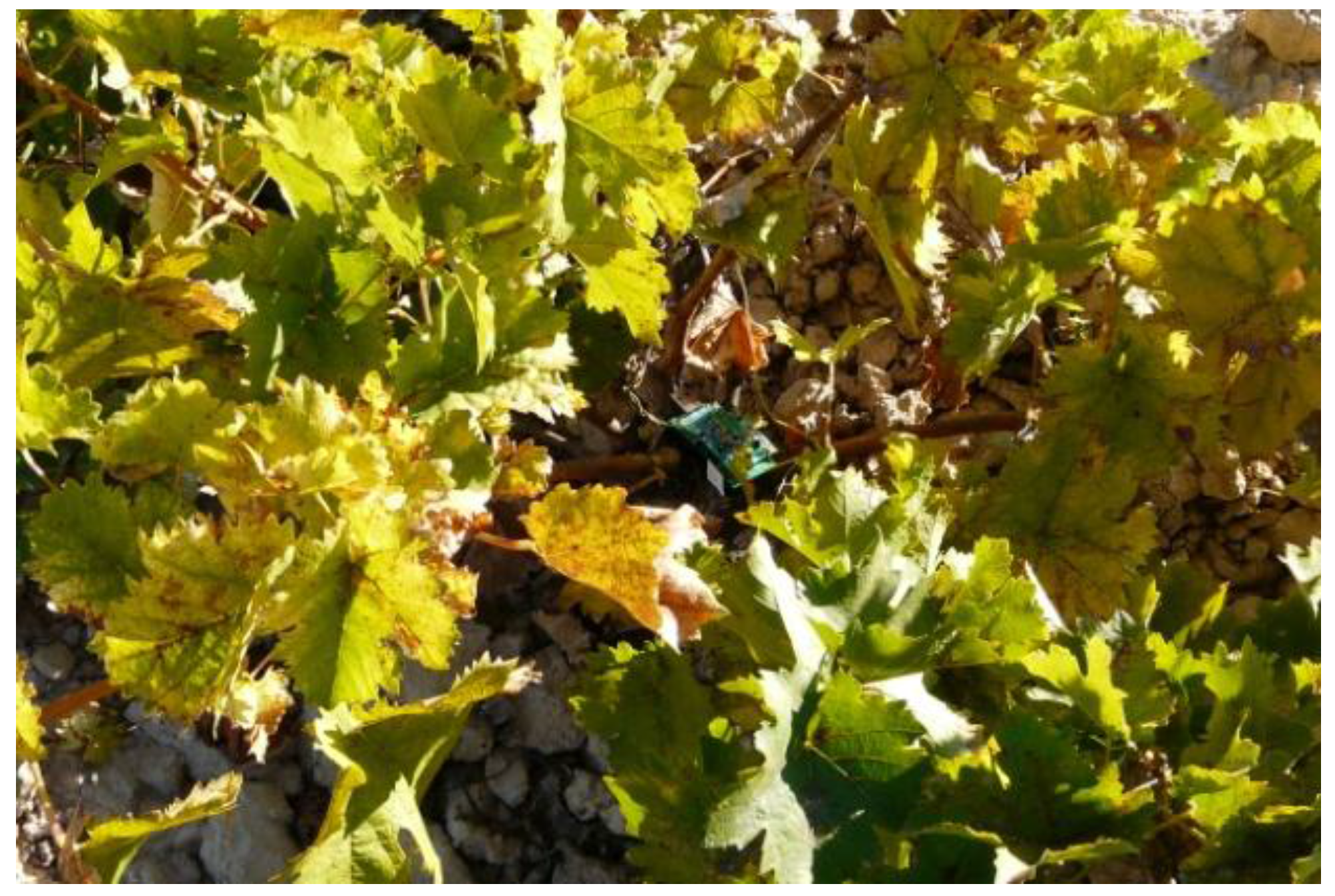
The second problem that WSN-based system has to deal with is the problem of communications between the nodes of each mesh network. Although the nodes are placed on the fields in a non-absolute random fashion, they try to organize themselves in a mesh topology. This structure improves reliability, but it is not enough since mesh communications are not always available. Communication problems arise since a vineyard is a dynamic natural system: nodes are subject to dense foliage growth (e.g., see Figure 1), animal intrusions and constant climatological changes. Thus, the internal communications in a cluster can be fully or partially affected, dividing the cluster in several sub-clusters or even isolating one or several nodes.
Since the manual repositioning of the nodes periodically is an impractical solution, over-sizing the network would be the only solution in order to decrease the probability for the lack of communication. However, increasing the number of nodes is not a robust solution, due to the economic, energetic, and computational costs involved.
In the described situation, the aim of this work is to provide farm managers with a friendly tool that improves situational awareness of their crop by using a WSN linked through a mobile node, carried by an UAV. The combined use of both systems has been already reported, showing their benefits and extendable applications by using fixed-wing aircraft [28]. This approach could present some drawbacks when typical short range and low consumption nodes are used. These nodes will probably require complex trajectories to be performed by fixed-wing aircraft. However, using aircrafts with hovering capabilities allows determining optimal static positions for bridging WSN nodes independently of the required download time. Additional facilities have been reported about the combined use of WSN and UAV’s, as the improvement of the navigation system by using nodes positions [29].
Figure 1. Active node surrounded of dense foliage from the vines.
Sensors 11 06088 g001

2. System Overview

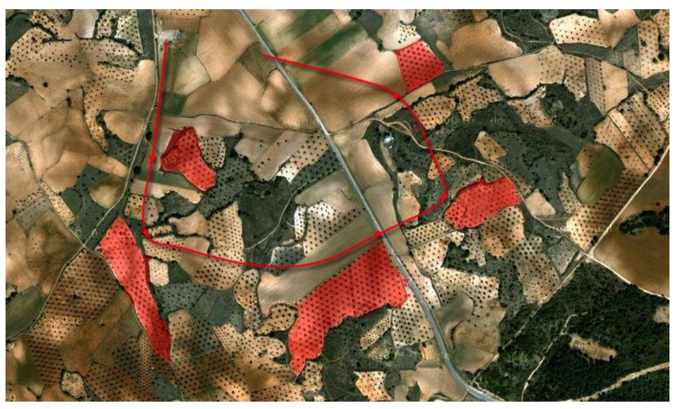
The proposed approach can be formulated as follows: Given a set of convex or/and non-convex cultivated land areas—denoted as parcels—isolated without the possibility of establishing a communication infrastructure among them (see Figure 2), a system that will be able to monitor a set of biophysical interesting variables in near real-time (i.e., frequently enough to prevent crop damages) and dispatch the information collected to a predefined end-user(s) or base-station(s) should be defined.
Figure 2. Several crop parcels where a desired aerial trajectory is depicted.
Sensors 11 06088 g002
Hence, from the communications point of view, each parcel will address a cluster that can be set up using one or several WSN nodes. Clusters are represented as a unique access point, since inside the cluster, nodes communicate among them using a mesh topology.
In order to cope with the limitations of the conventional WSN, such as short communication range, energy consumption, limited processing and storage capacity and low bandwidth, a hybrid system made up of three different elements is proposed:
  • Sensing system (WSN). It is made up of a split ground static wireless sensor network, which monitors the crop acquiring information in an intelligent manner (i.e., optimal sampling, storing and routing). This will be described in detail in Section 2.1.
  • Mobile node. Stationary nodes are combined with a mobile node carried by a mini aerial vehicle, employed as a remote dynamic data collector, analyzed in Section 2.2.
  • Long distance communications. Finally, the system is endowed with a packet oriented mobile data service connection, which provides a long distance communication channel. This is presented in Section 2.3.
A scheme of the system layout over the parcels is shown in Figure 3.
Figure 3. An illustrative example of the overall remote sensing mission.
Sensors 11 06088 g003

2.1. Sensing System: WSNs for Specific Data Acquisition
The sensor network is responsible for acquiring on-ground relevant information and communicating the data to the base station, using WSN nodes (or motes). The motes are small devices equipped with sensors, processing systems and communications resources. The points to be taken into account are data acquisition operation, time and requirements for the communication systems, field dimensions in relation with nodes and sensors, crop requirements, etc. These subject matters are dealt in this section.
Since the whole field-monitoring network is split into several clusters of different sizes, every part of the field is monitored by one or several clusters formed by one or more WSN nodes. The motes will acquire information about the soil, weather and/or crop status. These data will be relayed to the base station when an air vehicle flies over each cluster, sending the packets through a relaying node on the aerial drone, denoted as quadrotor.
This physical topology has been defined in order to provide enough flexibility to the network [28,29]. It also allows defining node layout according to terrain requirement and necessities, without considering communications constrains. In such manner, the number and performance of the nodes are increased, since node concentration varies according to the magnitude evolution in each terrain slide. In this sense, areas where the magnitudes-to-monitor do not highly change along the distance (e.g., temperature), it will be supervised with few nodes. On the contrary, zones where the variation of the magnitude is spatially unstable (e.g., gas concentration, vibrations) should be monitored with a tighter mesh. The best topology and layout for this network are determined experimentally: starting from a regular crystalline structure, magnitude evolution gradients are studied, in order to define variations focus. Having this data, it is possible to dynamically relocate the motes, obtaining finally a pattern adequate to the intrinsic terrain characteristics [30].
Nevertheless, communication links must be also taken into account. Node deployment shall optimize mote performance, but will also try to perform a mesh topology, allowing complete interaction among neighbored nodes. It allows downloading all data by situating the relay node (i.e., the quadrotor) in the surroundings of the clusters, avoiding the necessity of locating it accurately. The capacity for obtaining load information from any nearby point also allows defining optimum trajectories to cover every field. It clearly enhances the global performance of the system, and derives the complexity to the communication protocol [31]. The systems work properly when no regular meshes are defined—both initially due to operation circumstances, but with decreases in their performance. The scattering of the nodes in relation to communications only becomes significant when node distribution is actually atomized. Even in this particular case, the system architecture is able to guarantee a normal operation by increasing flight time and requirements of the resources.
Furthermore, not only mesh routing schemes should be considered. As the literature shows, most routing protocols are designed and defined for systems where nodes emit in discrete and punctual time intervals, being inactive and awaiting—with respect to communications—the rest of the time [32]. Nevertheless, this kind of architecture will saturate and overflow the network in our application, where big packet streams are simultaneously sent from every node, in order to minimize quadrotor harvesting/overfly time.
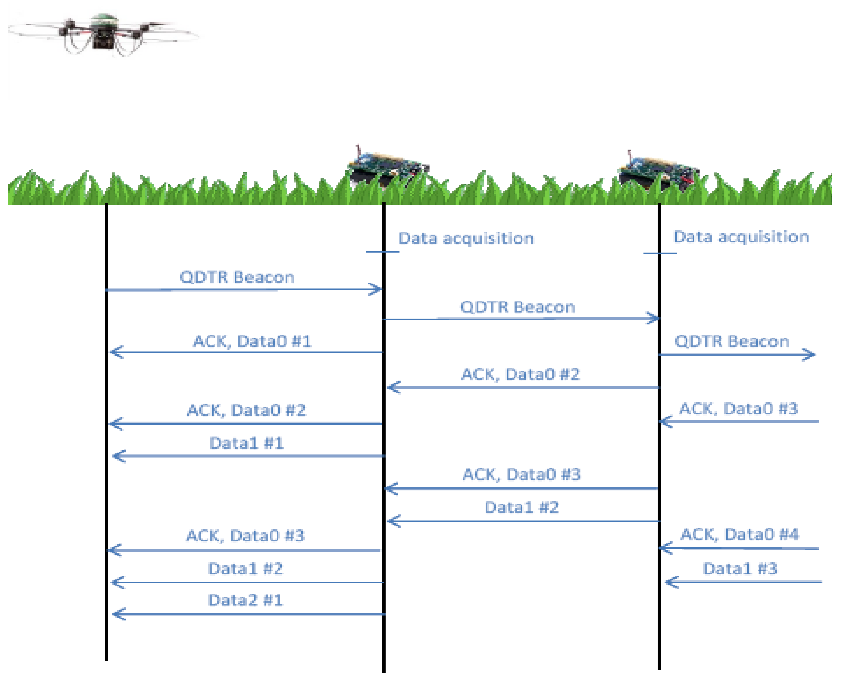
Most of the Medium Access Control (MAC) layer protocols are based on probability (randomly waiting to resend packets which have been lost due to collisions occurring), so the synchronization and communication time could be huge [33,34]. That is why a pipelined hierarchy organization was developed. Although this is not optimum or adaptable to any kind of general situations, it is absolutely appropriate in this context. In this manner, as Figure 4 shows, each node works individually, in an autonomous and iterative way, while the quadrotor is not in the surroundings. When it arrives, it communicates its presence to the network by means of a QDTR beacon, which will be spread along the mesh, configuring the paths for the routing scheme in the same action [35]. Once the hierarchy is set, according to the distance from each node to the sink (measured in number of hops), every node sends the data saved following the protocol presented in the Figure 4.
Thus, each node should maintain a number of packets inversely proportional to its distance to the quadrotor (d), with a latency time proportional to d-1. The way to guarantee the data pipeline in this multipath-reconfigurable system is to use CSMA/CD—included in IEEE 802.15.4 protocol—that delimits the access to the medium in conflictive areas [36]. This system is appropriate when the clusters are made up of few nodes so as not to overflow the system while allowing the required data to be stored.
Figure 4. Communications protocol.
Sensors 11 06088 g004
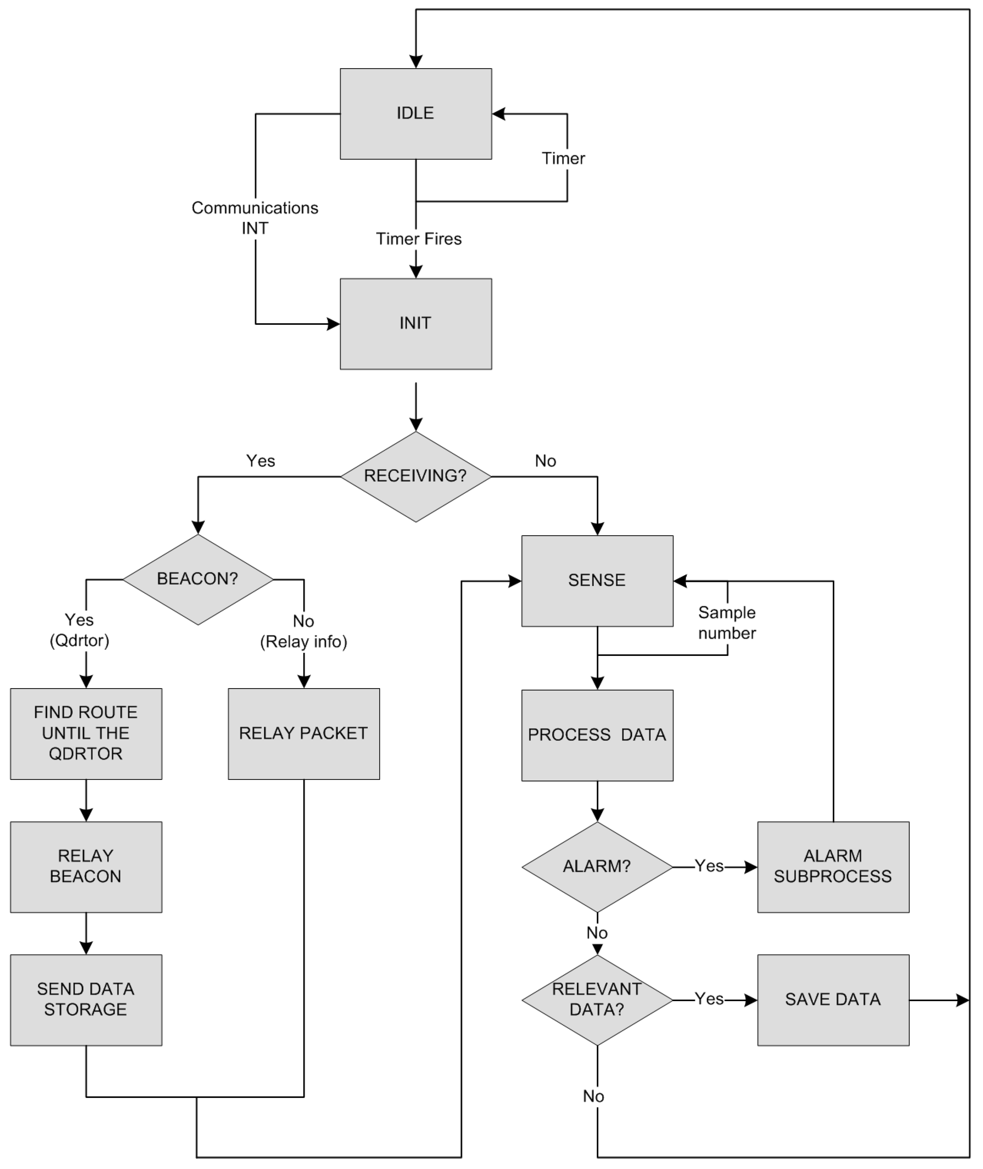
The algorithm that describes this operation is based on the state machine presented on Figure 5. As it can be observed, the initial state—and also the most common one—is low energy condition, or IDLE, this is due to the great importance of power consumption in WSN systems where battery lifetime is a critical issue. In this state, microcontroller, sensors and inputs/outputs are disabled except for communications (aerial and chip) and watchdog timing that are maintained awake.
At any time, both interfaces could trigger a system interruption: packet reception from the mobile node or timing signal that launches the acquisition process. Any of those events will prompt a node reactivation, which will wake the system interfaces and resources up. The base program will then be able to determine what caused the interruption.
In case of a temporal event, the measurement task will be turned on and the corresponding sensors will execute multiple micro delayed acquisitions. Although final accuracy depends on sensors’ precision, it allows to avoid punctual errors by applying the necessary filtering processes in the successive steps, as well as obtain a more realistic value. Besides, analyzed data will provide solutions for environmental pattern recognition, of alarm/critic state recognition and parameters required to dynamically adapt mote operation (such as sample time, number of samples per acquisition, secure range, etc.).
Finally, the data is encoded in order to maximize memory capacity and communication intervals. In this line, when similar values are obtained repeatedly (within a predefined range), new value is not stored. Instead, a heart bit in the package header indicates that the acquisition was successfully done and its result was similar to the previous one. Also, values are encoded depending on their frequency, in a similar procedure as used in Variable Length Coding (VLC) [37]. Once the information is encoded and stored, the control loop is reset and remains in IDLE mode until it receives a new interruption.
Figure 5. WSN mesh workflow.
Sensors 11 06088 g005
On the other hand, when the wake up is motivated by an incoming communication, the string is initially analyzed. Apart from the node number, the header is the same for every communication, because messages only flow among similar motes with the same communication standard, and differences appear in the payload. So, packet discrimination starts with the MESSAGE TYPE field. Two kinds of packets are considered: beacons sent by the quadrotor, and data packets sent by other motes to be relayed to the sink.
In the first case, the quadrotor beacons are in charge of waking the nodes up one by one and making up the mesh. It indicates that large communication resource is available and ready to receive their saved data. At the same time, beacons are also used for evaluating and defining feasible paths for the routing scheme. In such concept, every individual mote estimates quality and strength of the beacon message received. After putting this information in common and deciding globally which best path it is for each node, every mote starts sending information stored according to the protocol mentioned above. As mentioned, this process is kept while observing the respective tokens and while no reliable packets are present in the aerial. This second kind of packets enclose the information acquired and should be driven up to the sink.
Considering all of the above, both communications standards and WSN devices were analyzed and the ZigBee protocol was selected, since it was specifically designed for interconnect a huge number of nodes (up to 65,535 in the same network) split in multiple subnets with mesh topology, basing on IEEE 802.15.4 standard. Besides, its transmission data rate (250 kbp), power consumption and general performance are suitable for project’s definition [31].
On the other hand, multiple alternatives were available in the WSN device area. Nevertheless, in light of the computation requirements imposed by the communications and compression algorithms (8 MHz TI MSP430 microcontroller with 10 kB RAM), the high level of integration and robustness needed (antenna, sensors, etc.), and extremely low power consumption necessities (1.8 mA in active mode, 5.1 µA in IDLE mode), Crossbow’s TelosB motes were chosen [38].

2.2. Mobile Node: Aerial Robot as a Mobile WSN Node

The employed aerial platform to carry out this mission is a mini vertical takeoff and landing aircraft, denoted as quadrotor. Unlike helicopters, quadrotors provide simple assembly and maintenance due to their non-complex mechanical control linkages for rotor actuation. The vehicle control is done through variation of the speed of four fixed rotors. Recently, quadrotor manufacturers have been able to slightly increase payload capacity while maintaining a great maneuverability. Furthermore, due to the small dimensions and lightweight of the platform, safety and legislative issues are out of discussion. The small quadrotor employed in the experiments has the following characteristics:
  • Width: 0.63 m
  • Dimensions: 40 × 40 × 10 cm
  • Total weight: 550 grams
  • Payload: 200 grams
  • Spektrum DX7SE 2.4 GHz remote control
  • X-Bee 2.4 GHz data link
  • LiPo 11.1 V 2100 mAh
  • Maximum height: 500 m
  • The four rotors are made up of X-BL-52s brushless motors and their controllers.
  • Sensing capacity: GPS, IMU, 3D-MAG, pressure sensor.
  • The mainframe is made up of a power board and an autopilot card.
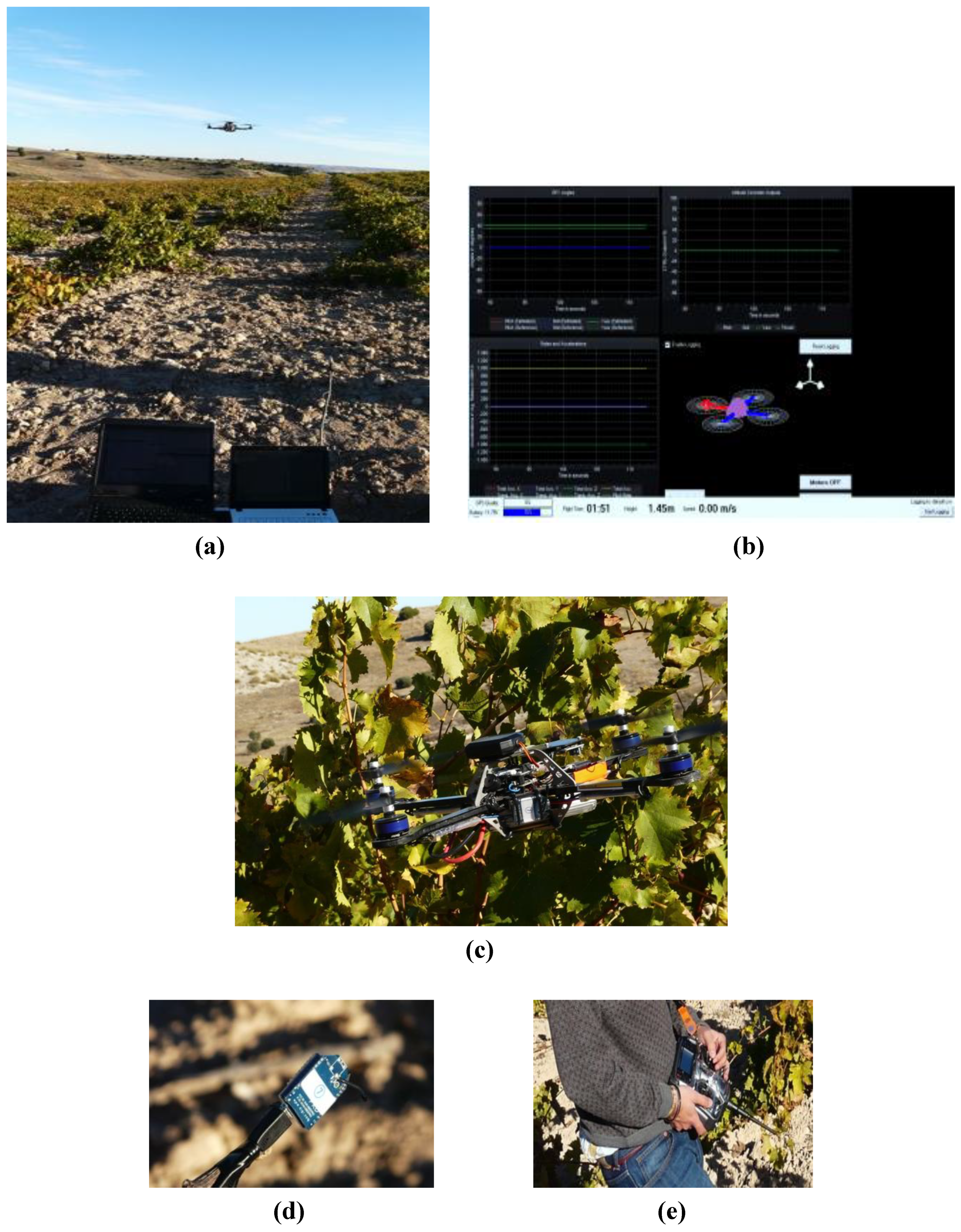
Position estimation is based on GPS that allows performing position control at 1 Hz, whereas attitude control is based on an Attitude and Heading Reference System (AHRS), which runs at 58.8 Hz. The sensor navigation data from the quadrotor can be received via wireless connection (Data link X-Bee at 2.4 GHz). The control commands can be sent to the vehicle using the R/C transmission radio control or the Data link X-Bee in write-mode. The operator is able to enter in the control loop at any time by using the radio control or through a Graphical Operator Interface (GOI) developed for the assessment of the mission proposed. The mission can also be manually aborted using the GOI shown in Figure 6. In this case two procedures can be followed: (i) the quadrotor will remain hovering to wait for operator commands or (ii) the quadrotor will return to the home-point (beginning of the mission) autonomously.
Figure 6. Aerial vehicle experimental setup. (a) Mobile base-station, (b) Quadrotor graphical operator interface, (c) Quadrotor, (d) Data link, (e) Emergency pilot remote control X-Bee.
Sensors 11 06088 g006

2.3. Communications Workflow: Relaying Data to the Base Station
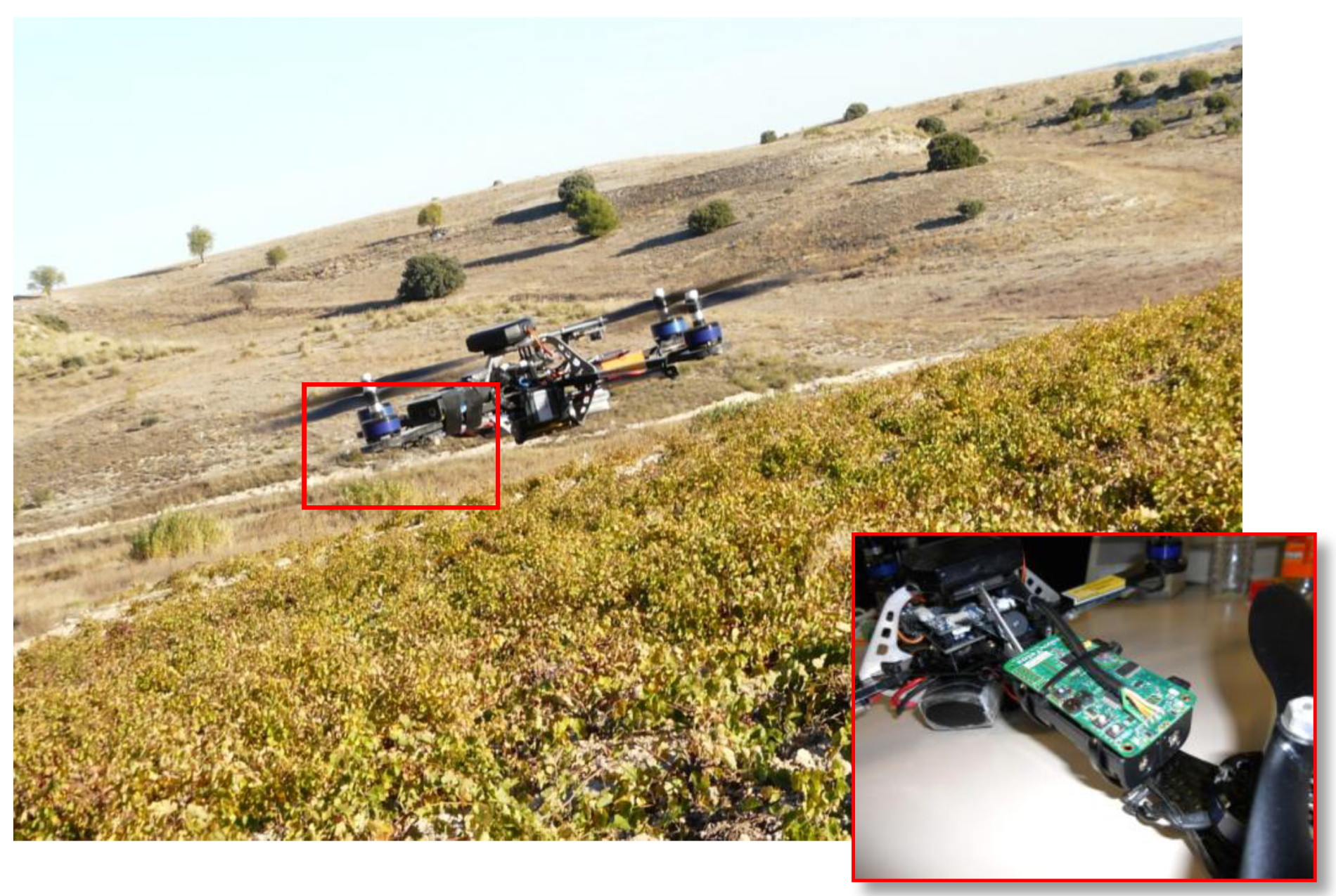
As previously mentioned, the air robot is responsible for shipping the bridges between the parcels and the base station. This mobile node is attached to one of the four frames of the quadrotor, taking into account drone mass distribution and inertia. Nevertheless, the motor throttles should be balanced in order to compensate mass deviation.
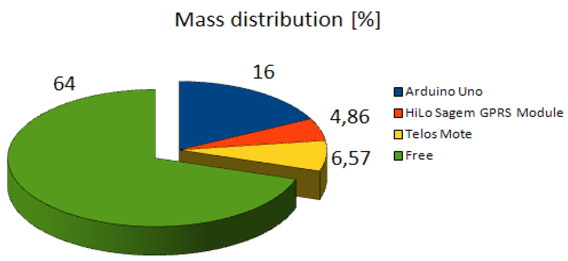
Additionally, it was also necessary to consider electromagnetic interferences (EMI) when placing and configuring the communication systems, in order not to affect quadrotor avionics, or mote capabilities (see Figure 7). Figure 8 shows the onboard mass distribution in the quadrotor employed, where the mote can be observed—including the communications and control devices—using less than 50% of the overall payload capacity.
Figure 7. Quadrotor flying over the vineyards shipping a mote. The attached mote is depicted in the bottom right inset.
Sensors 11 06088 g007
Figure 8. Quadrotor on-board mass distribution.
Sensors 11 06088 g008
In order to cope with the requirements of the mission such as dealing with the problems of long distances between the vineyard parcels and the base station, a packet-oriented mobile data connection service based in General Packet Radio Service (GPRS) has been adopted in order to communicate the drone with the base station. The GPRS connection allows relaying the sensor data from the motes within the vineyards until the base-station through wide distances. This solution is only limited by the quality of service (QoS) of the network provider, so it can be considered as robust and reliable. Unlike fixed GPRS modems, the modem shipped on the drone allows transmitting data overcoming GPRS shadow areas—commonly found outside urban areas—in the parcels. The data is stored and then later transmitted as soon as the drone reaches areas with communication coverage,
An additional feature for the system can be using Short Message Service (SMS), which allows sending messages to farm managers periodically, and thereby increasing their situation of awareness. The system previously mentioned is based on Arduino Uno board and GPRS Quad band module, which include a HiLo SAGEM communication module (see Figure 9).
Figure 9. Arduino system employed for communication with the base station, likewise for message delivery.
Sensors 11 06088 g009
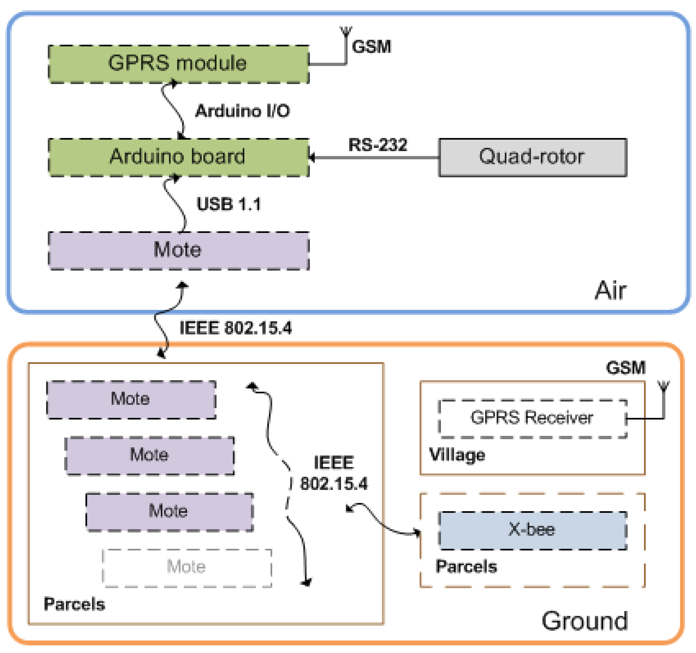
The overall Ground-Air communication system is shown in Figure 10, and works as follows: the main component of the air sub-system (shown on the top of Figure 10) is the Arduino board that reads the data from the quadrotor, likewise from the TelosB mote. The data is read from the quadrotor at a frequency of 2 Hz, and from the mote at a frequency of 4 Hz. The Arduino is always on stand-by. The reading mode is activated every time the onboard node senses a reliable sign from a ground WSN distributed over a parcel (i.e., the signal quality should be greater than a defined threshold). This data is then dispatched to the base station that is shown in the bottom layer, with respect to the ground sub-system, and consequently sent by SMS to the farm manager if the temperatures drop the critical values. It allows a previous reaction (earlier to the damaging effects, but reactive to some past circumstances). In the base-station, the biophysical parameters (e.g., temperature, humidity, etc.) are stored with respect to the waypoint that maps the parcel. It should be taken into account that each waypoint corresponds to a parcel, which is indeed covered by a single WSN. The waypoint coordinates are computed with an iterative genetic algorithm (GA) that computes an optimal hovering position within each parcel. We understand optimal hovering position as the position where there is more ground nodes covered by the aerial node.
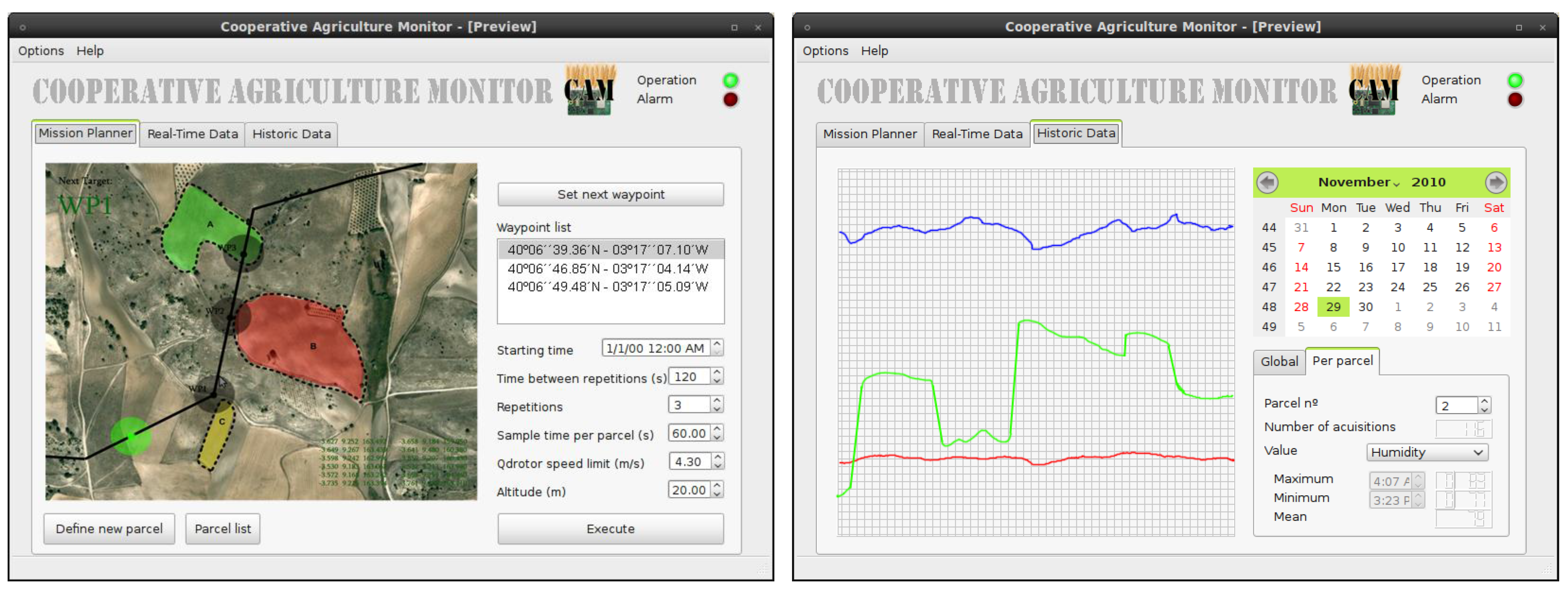
This stored information could be analyzed, managed and visualized using a specific tool specially developed for this application. This instrument is prompted as a Graphical User Interface (GUI), and provides crop managers with a simple way to define the mission targets and likewise to store-visualize and manage the data acquired over the parcels (see Figure 11). Therefore, it has a double purpose: on the one hand, showing, storing and processing collected information in order to analyze relevant factors (tendency, evolutions, critical points, etc.) in a simple way. On the other hand, providing a user-friendly tool to manage missions that only requires selecting targeted parcels by clicking over them in the map, and defining the mission parameters (such us sample time per parcel, flight altitude or elapsed time between repetitions). This information is directly configured in the air drone.
Figure 10. Ground-Air system communications.
Sensors 11 06088 g010
Figure 11. GUI employed in the base-station to aid the crop managers to carry out the frost monitoring mission.
Sensors 11 06088 g011

3. Case Study and Experimental Results
A set of experiments have been carried out in a wine production region at the northwest of Madrid, Spain [39] with the purpose of demonstrating the effectiveness of the proposed system. The cultivated parcels where the experiments have been carried out are reported by crop managers to be one of the most injured areas from the Spring season frost. It is a major problem in these areas since climate poses a major threat of plant injury due to low-temperature. That is why active frost protection to prevent damage to fruits is required. The protection method is initiated just prior to the air temperature reaching the critical temperature for crop damage and shut down when the low-temperature damage has dissipated. In all cases, frost/freeze protection involves workers monitoring air temperatures throughout the crop. Indeed, all frost/freeze protection systems are costly in terms of capital, labor, and operating costs. Hence, this is the appropriate domain to integrate and test our proposal, by acquiring information of the atmospheric temperature [40], the relative humidity [40] and ambient light [41].
The experiments were limited to three parcels from this critical region. The parcels have approximately an area of 0.5 up to 4 hectares. It should be highlighted that they are separated from each other at a distance of 70 to 100 m.
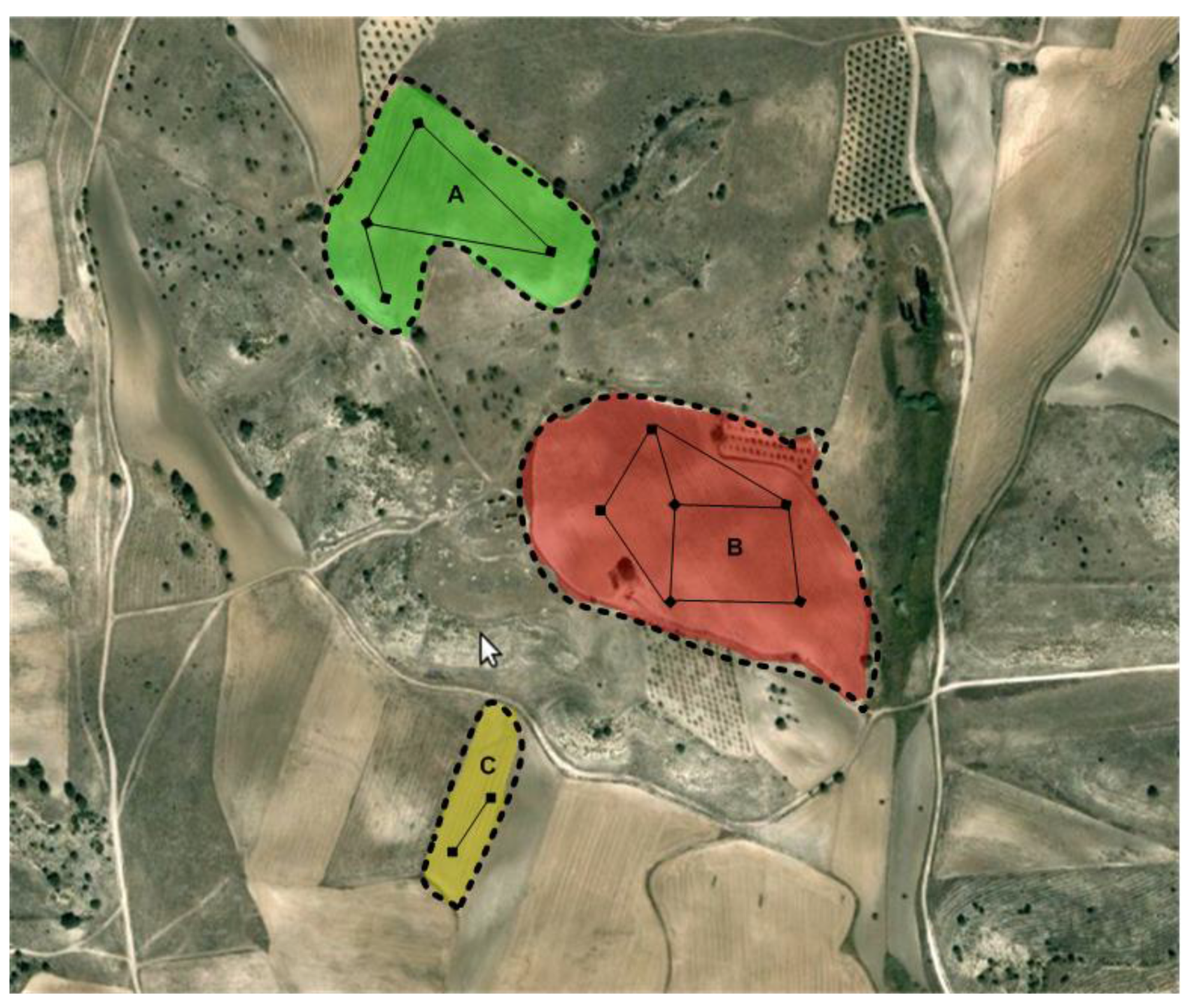
To test the reliability of ground communications among the nodes from each mesh network, a preliminary experiment was carried out. In this experiment, 10 motes were used; three in area A, four in area B and three in area C (see Figure 12). This experiment makes it possible to test if nodes are almost randomly distributed (i.e., keeping a distance not greater than 30 m between them) in an unstructured terrain and could maintain the network workload. Table 1 shows the overall signal quality and packets lost from each mesh network.
Figure 12. The three parcels adopted for the experimental scenario with the corresponding WSN arrangements.
Sensors 11 06088 g012
This result plays an important role in the workload analysis, since they give a quantitative magnitude of the end-to-end signal accuracy, discarded and resent beacons, and consequently the network lifetime. For a question of simplicity, the parcels have been configured in such a way that each parcel has a single stable communication cluster. Since the WSN from each parcel have their nodes spread with different average dispersions, we can evaluate the distance between nodes that is most favorable, given the site physical characteristics and the number of motes available. The signal quality is obtained for each mote through the follow equation:
% S i g n a l Q u a l i t y = S i g n a l   N o i s e   ×   S N R
where Signal, Noise, and SNR (Signal-to-noise ratio) are given in db. Moreover, the packets lost for each mote are given by:
% P a c k e t s L o s s = ( 1 P r e c e i v e d P s e n t )   × 100
where Psent and Preceived and stand for packages sent and received, respectively. Therefore the Signal quality and the Packet lost presented in Table 1 are the average value for each parcel.
Table 1. Signal quality and packets lost during the remote sensing mission for each cluster.
ParcelsAverage dispersion [m]Signal quality [%]Packets lost [%]
A1080.34.1
B2073.26
C3059.96.7
The second set of experiments performed was dedicated to measuring the signal acquired on flight with the dynamic node carried by the quadrotor. The vehicle flew over the aforementioned parcels with the previous average dispersions. In each parcel the dynamic node received beacons from the ground cluster at three different heights, as shown in Table 2. Therefore, the reliability of communication at different heights and the area for the number of nodes to cover (i.e., where there is a reliable communication link) by the dynamic node has been analyzed.
Table 2. Signal quality and packets lost during the remote sensing mission for each cluster.
ParcelsFlight height [m]Signal quality [%]Packets lost [%]Nodes covered
A1095.20.8100%
A2093.91.7100%
A30841.1100%
B1093.81.2100%
B2090.21.3100%
B3083.71.491% (10/11)
C10950.9100%
C20911100%
C3087.43100%
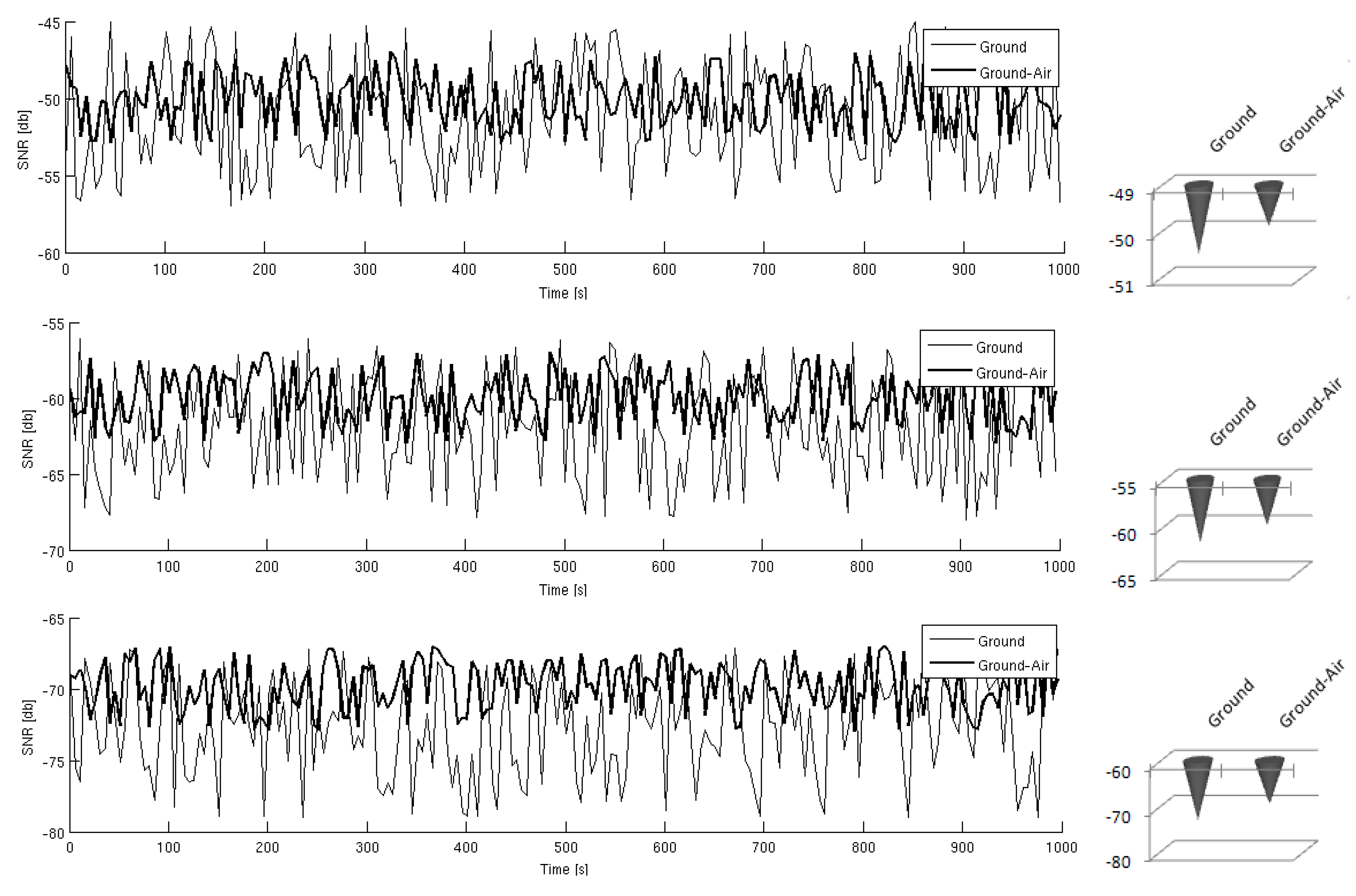
The results from Table 1 and Table 2 illustrate how WSN links are considerably improved with the presence of an elevated node. It confirms initial suppositions about worse ground performance due to the natural unstructured conditions of the crop. In general terms, it improves the average signal quality in 19%. The SNR has been also computed for each node, likewise the average SNR for each WSN within each parcel. In Figure 13 the average SNR values over a given time are shown on the left column, and the mean values during that period can be observed on the right column. The analysis of those plots have shown that SNR mean values are higher when using Ground-Air WSN link compared to using the Ground WSN, making the presence of the relay elevated node advisable.
Figure 13. Average SNR obtained for the WSNs from each parcel. From top to down, A, B, C, respectively.
Sensors 11 06088 g013
Table 3 shows values from the aerial robot (i.e., dynamic node) acquired during the survey over the parcels. The waypoints are optimal points where the aerial robot passes over and they have to be set up previously to define the mission. Furthermore, the update time represents the time that the aircraft needs to stay above ground in order to obtain the signal from the target cluster. It should also be noted that the quality of the signal and the count of lost packets shown in Table 3 refer to the communications between the dynamic node and the emitter ground node.
Table 3. Values from the aerial robot (i.e., dynamic node) survey mission.
ParcelsTimeWay-pointUpdate TimeBatteryQuadrotor speedSignal qualityPackets lost
A17 h:45 m:14 s
08/12/2010
40°06''49.48'N
03°17''05.09'W
71 s12.51 V5 m/s92.3%2%
B17 h:47 m:32 s
08/12/2010
40°06''46.85'N
03°17''04.14'W
83 s12.37 V5 m/s89.7%3%
C17 h:50 m:43 s
08/12/2010
40°06''39.36'N
03°17''07.10'W
76 s12.02 V5 m/s96%1%
As previously mentioned, the experiments were performed both in the morning and afternoon. Since the climate has considerably changed during this season, we had the opportunity to validate our system at different wind speeds. Table 4 shows the parameters and results from those experiments, monitoring the battery status after the experiments and the overall duration of the aerial vehicle trajectory. In both experiments the quadrotor speed was set to 5 m/s and both experiments were made with full charged batteries. In the morning (Experiment 1) with regular wind speeds, the mission was carried out more quickly than in the afternoon (Experiment 2). We have realized that each time the wind speed increased, the aerial vehicle was displaced from the desired aerial trajectory, forcing the vehicle to constantly rectify this route, which has consumed more time and efforts from the system.
Table 4. The two experimental sets summed up focusing in the mission time and battery consumption.
ExperimentsWind speedAerial Robot velocityBattery statusMission duration
14.2 m/s5 m/s10.23 V191 s
28.9 m/s5 m/s9.25 V276 s
A sole 2,100 mAh battery was used for drone electronics, motors, mote and communications. During the experiments, the drone was able to fly with this battery along 5,000 m at a 5 m/s maximum velocity. This value substantially depends on the number of waypoints and the hovering time required to obtain all the data as well as the wind conditions.

4. Conclusions

In this paper, an innovative and a general solution based on a combination of UAV and WSN to monitor variables from fragmented crop fields has been proposed. Problems related to fragmentation of the regions of interest in a wide area such as the impossibility of deploying a fully connected WSN, the large distances to cover and the continuous monitoring of the environment variables can be overcome with the proposed approach.
Such problems have been tackled with the basic idea of a mobile WSN node that can periodically recollect the information of the sub-networks deployed in each one of the regions of interest. Since the mobile part is an airborne node, problems related to the nature of the ground are easily overcome.
The main contributions of this work are the use of UAVs as airborne communication nodes and the resolution of the problems regarding WSN dynamic configuration when a UAV is approaching to the target area. An ad-hoc communication protocol and a communication workflow have been implemented in order to deal with such issues.
In addition to this, a user-friendly operator interface that allows handling the system and monitoring data has been implemented. It should be highlighted that cheap and reliable UAV platforms are currently available and they can be easily used in this kind of applications. This work provided the opportunity to test the use of a commercial quadrotor in a real scenario. The UAV was able to successfully perform its missions, flying under different wind conditions.
The proposed system has been designed in order to assess the viability of monitoring frost in vineyards during the spring season, but the same approach can be also adopted in other applications with similar characteristic related to agricultural issues or not.
A set of experiments have revealed that both the user interface of the base station and the alert systems based on SMS have increased situation awareness, providing crop managers with crop health status in real-time. In particular, temperature and humidity status from vineyards parcels that are useful in order to prevent damage and loss due to frosts.
Although the experimental results have been obtained using a three-parcel scenario, the system is completely scalable. Experimental results have shown that this approach provides many advantages considering ground WSN, such as improvement of the WSN communication workflow, improvement of the data routing to the base station, and a better monitoring of the crop.
In conclusion, we believe that the proposed approach has a great potential for remote crop monitoring using wireless sensor networks technology. Moreover, it also overcomes many of its limitations in the kind of scenario at hand.

Acknowledgements

This work was supported by the Robotics and Cybernetics Group and the Artificial Perception Group at the Automatic and Robotics Centre (CAR) UPM-CSIC, and funded under the project ROBOCITY 2030 Project, sponsored by the Community of Madrid (S-0505/DPI/000235). The authors would also like to thank Andrés Morate (http://www.andresmorate.com) for providing the vineyards to carry out the experiments.

References and Notes

  1. Kropff, M.; Wallinga, J.; Lotz, L. Modelling for Precision Weed Management. In Proceedings of Ciba Foundation Symposium 210—Precision Agriculture: Spatial and Temporal Variability of Environmental Quality, Chichester, UK, 27 September 2007; pp. 182–207.
  2. Blackmore, S.; Wheeler, P.; Earl, R. Precision Farming: The Management of Variability. Landwards 1996, 51, 18–23. [Google Scholar]
  3. Srinivasan, A. Handbook of Precision Agriculture: Principles and Applications; CRC: New York, NY, USA, 2006. [Google Scholar]
  4. Sudduth, K.; Hummel, J.; Birrell, S. Sensors for Site-Specific Managemen. In The State of Site Specific Management for Agriculture; ASA-CSSA-SSSA: Madison, WI, USA, 1997; pp. 183–210. [Google Scholar]
  5. Akyildiz, I.F.; Su, W.; Sankarasubramaniam, Y.; Cayirci, E. Wireless Sensor Networks: A Survey. Comput. Netw. 2002, 38, 393–422. [Google Scholar] [CrossRef]
  6. Xiong, S.-M.; Wang, L.-M.; Qu, X.-Q.; Zhan, Y.-Z. Application Research of WSN in Precise Agriculture Irrigation. In Proceedings of International Conference on Environmental Science and Information Application Technology, Wuhan, China, 4–5 July 2009; Volume 2, pp. 297–300.
  7. de Lima, G.H.E.L.; e Silva, L.C.; Neto, P.F.R. WSN as a Tool for Supporting Agriculture in the Precision Irrigation. In Proceedings of International Conference on Networking and Services, Cancun, Mexico, 7–13 March 2010; pp. 137–142.
  8. Kim, Y.; Evans, R.; Iversen, W. Remote Sensing and Control of an Irrigation System Using a Distributed Wireless Sensor Network. IEEE Trans. Instrum. Meas. 2008, 57, 1379–1387. [Google Scholar]
  9. Shinghal, K.; Noor, D.; Srivastava, D.; Singh, D. Wireless Sensor Networks in Agriculture: For Potato Farming. Int. J. Eng. Sci. 2010, 2, 3955–3963. [Google Scholar]
  10. Anastasi, G.; Farruggia, O.; Re, G.L.; Ortolani, M. Monitoring High-Quality Wine Production using Wireless Sensor Networks. In Proceedings of the 42nd Hawaii International Conference on System Sciences, Big Island, HI, USA, 5–8 January 2009; pp. 1–7.
  11. Yoo, S.; Kim, J.; Kim, T.; Ahn, S.; Sung, J.; Kim, D. A2S: Automated Agriculture System Based on WSN. In Proceedings of IEEE International Symposium on Consumer Electronics, Dallas, TX, USA, 20–23 June 2007; pp. 1–5.
  12. Siuli Roy, A.; Bandyopadhyay, S. Agro-Sense: Precision Agriculture Using Sensor-Based Wireless Mesh Networks. Innovations in NGN—Future Network and Services. In Proceedings of An IT U-T Kaleidoscope Conference, Geneva, Switzerland, 12–13 May 2008; pp. 383–388.
  13. Yamaha Inc. Yamaha autonomous-flight unmanned helicopter deployed for observation illegal dumping around Mt. fuji., 2011.
  14. Zarco-Tejada, P.; Berni, J.; Suárez, L.; Fereres, E. A new era in remote sensing of crops with unmanned robots. SPIE Newsroom 2008. [Google Scholar] [CrossRef]
  15. Herwitz, S.; Dunagan, S.; Sullivan, D.; Higgins, R.; Johnson, L.; Zheng, J.; Slye, R.; Brass, J.; Leung, J.; Gallmeyer, B.; Aoyagi, M. Solar-Powered UAV Mission for Agricultural Decision Support. In Proceedings of the IEEE International Geoscience and Remote Sensing Symposium, Toulouse, France, 21–25 July 2003; Volume 3, pp. 1692–1694.
  16. Herwitz, S.; Johnson, L.; Dunagan, S.; Higgins, R.; Sullivan, D.; Zheng, J.; Lobitz, B.; Leung, J.; Gallmeyer, B.; Aoyagi, M.; et al. Imaging from an Unmanned Aerial Vehicle: Agricultural Surveillance and Decision Support. Comput. Electr. Agr. 2004, 44, 49–61. [Google Scholar] [CrossRef]
  17. Johnson, L.; Herwitz, S.; Dunagan, S.; Lobitz, B.; Sullivan, D.; Slye, R. Collection of Ultra High Spatial and Spectral Resolution Image Data over California Vineyards with a Small UAV. In Proceedings of the 30th International Symposium on Remote Sensing of Environment, Honolulu, HI, USA, 10–14 November 2003.
  18. Herwitz, S.; Slye, R.; Dunagan, S.; Lobitz, B.; Johnson, L. Nighttime UAV Vineyard Mission: Challenges of See-and-Avoid in the U.S. National Airspace. In Proceedings of AIAA 3rd Unmanned Unlimited Technical Conference, Workshop and Exhibit, Chicago, IL, USA, 20–23 September 2004.
  19. Sugiura, R.; Noguchi, N.; Ishii, K. Remote-sensing Technology for Vegetation Monitoring using an Unmanned Helicopter. Biosyst. Eng. 2005, 90, 369–379. [Google Scholar] [CrossRef]
  20. Iwahori, T.; Noguchi, N.; Ishii, K.; Sugiura, R. Development of GIS Map Generation System Using an Unmanned Helicopter; Technical Report 051020; American Society of Agricultural and Biological Engineers: St. Joseph, MI, USA, 2005. [Google Scholar]
  21. Rovira-Más, F.; Zhang, Q.; Reid, J. Creation of Three-Dimensional Crop Maps based on Aerial Stereoimages. Biosyst. Eng. 2005, 90, 251–259. [Google Scholar] [CrossRef]
  22. Chao, H.; Baumann, M.; Jensen, A.; Chen, Y.; Cao, Y.; Ren, W.; McKee, M. Band-Reconfigurable Multi-UAV-Based Cooperative Remote Sensing for Real-Time Water Management and Distributed Irrigation Control. In Proceedings of IFAC World Congress, Seoul, Korea, 6–11 July 2008.
  23. Johnson, H.; Robinson, J.; Limited, O.P.G. The World Atlas of Wine; Mitchell Beazley: London, UK, 2001. [Google Scholar]
  24. Tongrod, N.; Tuantranont, A.; Kerdcharoen, T. Adoption of Precision Agriculture in Vineyard. In Proceedings of the 6th International Conference on Electrical Engineering/Electronics, Computer, Telecommunications and Information Technology, Pattaya, Thailand, 6–9 May 2009; Volume 2, pp. 735–738.
  25. Beckwith, R.; Teibel, D.; Bowen, P. Unwired Wine: Sensor Networks in Vineyards. Proc. IEEE Sensors 2004, 2, 561–564. [Google Scholar]
  26. Burrell, J.; Brooke, T.; Beckwith, R. Vineyard Computing: Sensor Networks in Agricultural Production. IEEE Pervasive Comput. 2004, 3, 38–45. [Google Scholar] [CrossRef]
  27. Romero Risalde, F.J. Central termica de biomasa de 5 Mw de potencia. Anexo 5: Estudio de la distribucion del viñedo por superficie y numero de parcelas. M.S. Thesis, Universidad de Castilla-La Mancha, Ciudad Real, Spain, 2005. [Google Scholar]
  28. Teh, S.K.; Mejias, L.; Corke, P.; Hu, W. Experiments in Integrating Autonomous Uninhabited Aerial Vehicles (UAVs) and Wireless Sensor Networks. In Proceedings of the Australasian Conference on Robotics and Automation, Canberra, Australia, 3–5 December 2008.
  29. Dang, P.; Lewis, F.L.; Popa, D.O. Dynamic Localization of Air-Ground Wireless Sensor Networks. In Advances in Unmanned Aerial Vehicles; Valavanis, K.P., Ed.; Springer: Dordrecht, The Netherlands, 2007; pp. 431–453. [Google Scholar]
  30. Poe, W.Y.; Schmitt, J.B. Node Deployment in Large Wireless Sensor Networks: Coverage, Energy Consumption, and Worst-Case Delay. In Proceedings of Asian Internet Engineering Conference, Bangkok, Thailand, 18–20 November 2009; pp. 77–84.
  31. Puccinelli, D.; Haenggi, M. Arbutus: Network-Layer Load Balancing for Wireless Sensor Networks. In Proceedings of Wireless Communications and Networking Conference, Las Vegas, NV, USA, 31 March–3 April 2008; pp. 2063–2068.
  32. Xiang, X.; Guo, X. Zigbee Wireless Sensor Network Nodes Deployment Strategy for Digital Agricultural Data Acquisition. In Computer and Computing Technologies in Agriculture III; Li, D., Zhao, C., Eds.; Springer: Boston, MA, USA, 2010; Volume 317. [Google Scholar]
  33. Salhieh, A.; Weinmann, J.; Kochhal, M.; Schwiebert, L. Power Efficient Topologies for Wireless Sensor Networks. In Proceedings of International Conference on Parallel Processing, Valencia, Spain, 3–7 September 2001; pp. 156–163.
  34. Förster, A.; Murphy, A.L. A Critical Survey and Guide to Evaluating WSN Routing Protocols. In Proceedings of The First International Workshop on Networks of Cooperating Objects, Stockholm, Sweden, 12 April 2010.
  35. Abramson, N. The ALOHA System: Another Alternative for Computer Communications. In Proceedings of the Fall Joint Computer Conference, Montvale, NJ, USA, 17–19 November 1970; pp. 281–285.
  36. Ziouva, E.; Antonakopoulos, T. CSMA/CA Performance under High Traffic Conditions: Throughput and Delay Analysis. Comput. Commun. 2002, 25, 313–321. [Google Scholar] [CrossRef]
  37. Bauer, R.; Hagenauer, J. On Variable Length Codes for Iterative Source/Channel Decoding. In Proceedings of Data Compression Conference, Snowbird, UT, USA, 2001; pp. 273–282.
  38. The experiments were carried using TelosB motes. Available online: http://bullseye.xbow.com:81/Products/Product_pdf_files/Wireless_pdf/TelosB_Datasheet.pdf/ (accessed on 26 May 2011).
  39. The experiments were carried from 25 October–December 2010.
  40. Sensirion SHT11: Temperature and Relative Humidity Sensor. Available online: http://www.sensirion.com/en/pdf/product_information/Datasheet-humidity-sensor-SHT1x.pdf/ (accessed on 26 May 2011).
  41. Hamamatsu S108: Visible light sensor. Available online: http://sales.hamamatsu.com/assets/pdf/parts_S/S1087_etc.pdf/ (accessed on 26 May 2011).