2.1. Static Foreground Region Segmentation
In traditional detection, the temporary-background difference method is used to detect static objects for surveillance systems [
13,
14]. It has a two layer background. The first layer is to store the original background, which is established
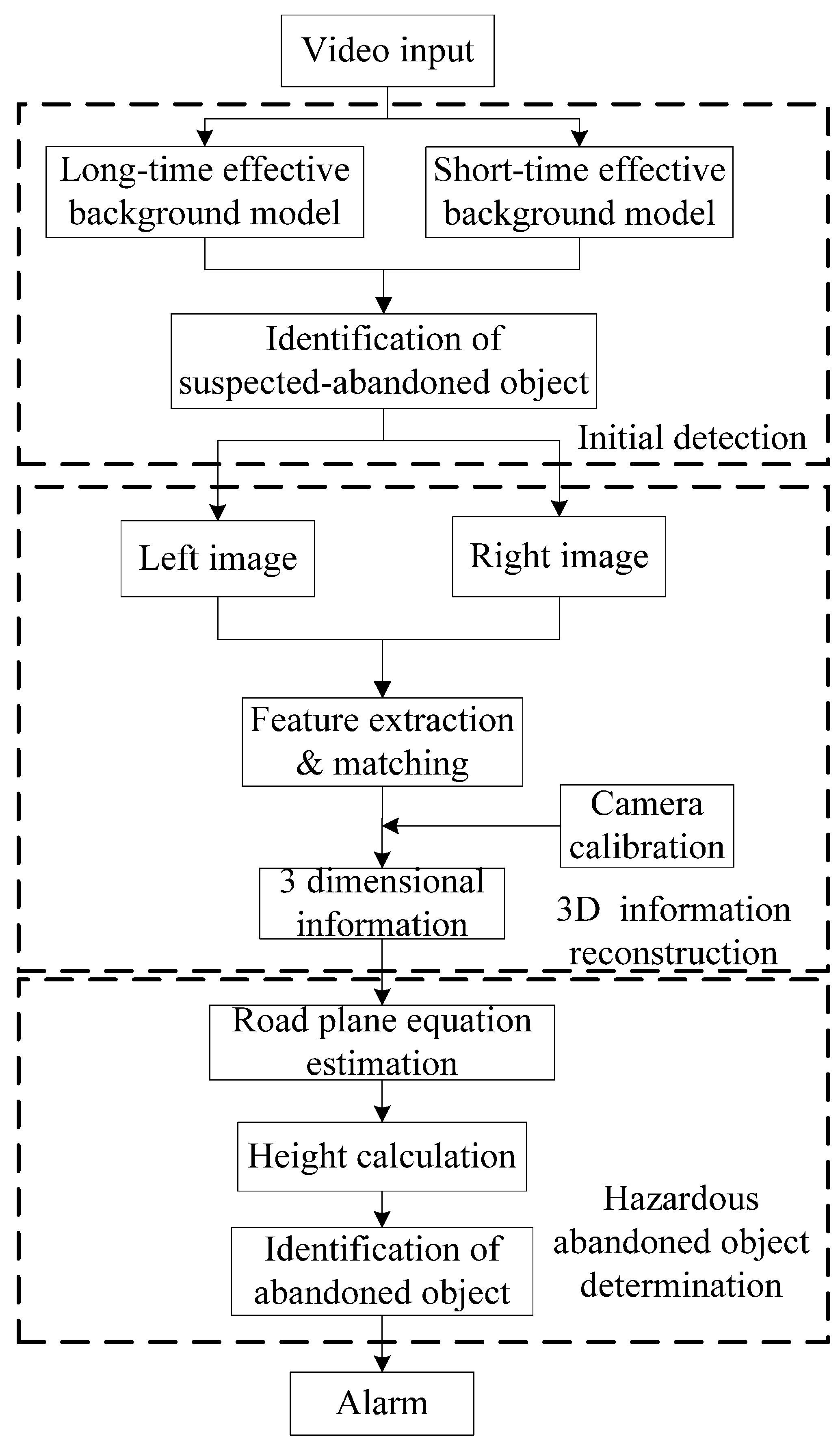
a priori. The second layer stores the updated background. In order to adapt to complex environments, backgrounds will be re-established at regular intervals. The new background becomes the current background and the old background becomes the previous background at the same time. Because of background updating, the suspected abandoned object will have blended into the current background after updating the background for a while, thus static objects can be calculated by seeing the difference between the first layer background and the second layer background. The temporary-background difference method can effectively detect static foreground objects, but holes in the object region and discrete noise will affect the detection accuracy when the target size is small. Meanwhile, stationary vehicles and people may be regarded as abandoned objects, so a novel static foreground object segmentation method based on a dual-background difference algorithm is proposed for road surveillance in this paper. The short-term background model and long-term background model are established first, and then the static foreground region will be obtained through the above two models. Finally, the static foreground region is regarded as a suspected abandoned object.
A. Short-term background modeling and updating
The short-term background model has a faster updating rate. It makes stationary targets blend into the background in a short time due to this fast updating rate. The traditional Surendra algorithm can acquire the background quickly, but it does not perform further processing of frame differences [
15]. This existing problem may cause a cross-regional foreground with similar texture to be regarded as background. In addition, the extracted region of motion is often greater than the actual region, which leads to detection inaccuracy. In order to solve this problem, an improved Surendra background molding algorithm is proposed in this paper to establish the short-term background. The algorithm calculates the motion region based on a three frame difference. It keeps background points unchanged in the motion region and updates background points using the current and former two frames in the non-motion region, so background images can be extracted after a period of time. The algorithm can be divided into the following steps:
- (1)
Define the first image
as background image
;
- (2)
Set the number of iterations as N;
- (3)
Get binary difference image between current frame and previous frame:
and the binary difference image of former two frames is:
where
is the current frame and
,
are the former two frames;
is the difference image between two consecutive frames;
and
are thresholds for binarization.
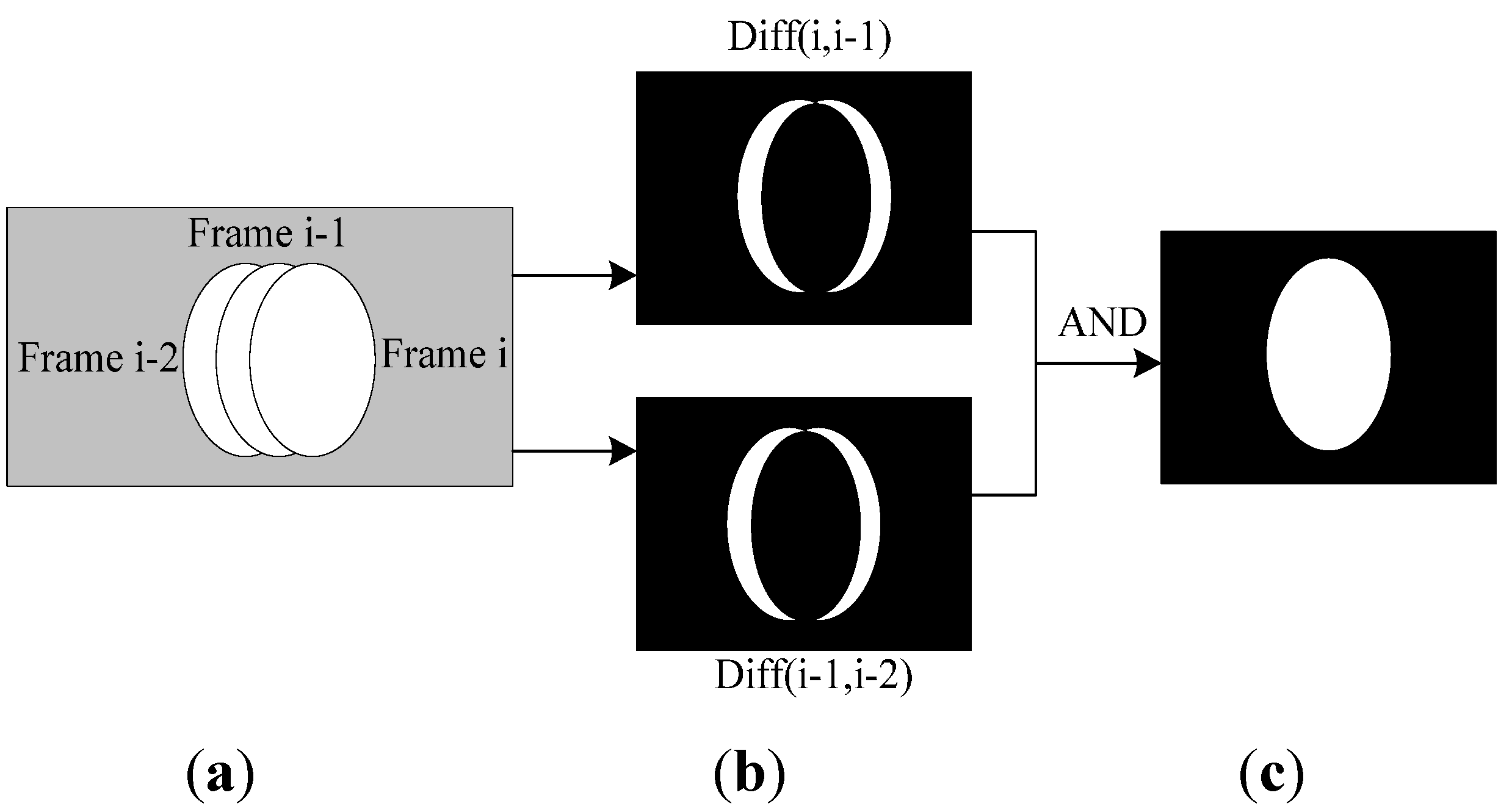
- (4)
Obtain the binary motion region edge by using the ‘AND’ operation
and background subtraction method [
16] shown as follow is adopted to fill the region:
where
represents the current background image of the binary motion region. The binary motion region extraction is shown in
Figure 5.
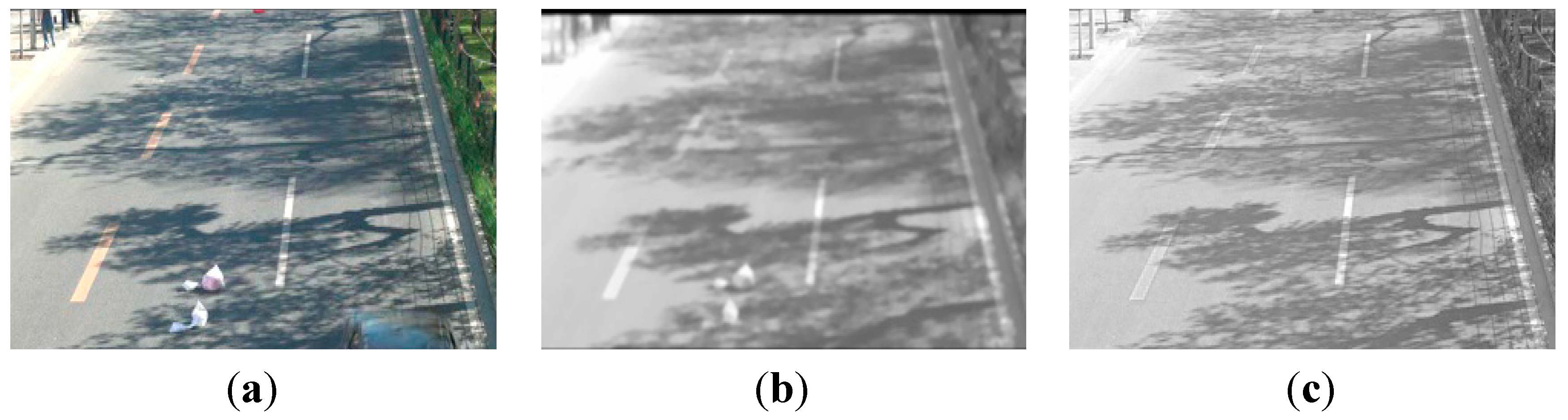
Figure 5.
Binary motion region extraction. (a) motion region in three sequent frames; (b) binary difference image; (c) Binary motion region extraction result.
Figure 5.
Binary motion region extraction. (a) motion region in three sequent frames; (b) binary difference image; (c) Binary motion region extraction result.
- (5)
Update the instant background
by binary motion region image
as follows:
Then, the new background
will be updated by the following formula:
where
is the update rate.
- (6)
Let
, return to step 3 and iterate. The iteration will finish when , then
is regarded as extracted background.
This algorithm can quickly adapt to real-time changes in the background image, and especially adapt to changes of light. It does not need to initialize the background, and background image can be quickly extracted by iteration. The background has a fast update rate, so the static objects can blend into the background quickly.
B. Long-term background modeling and updating
This paper selects an improved Gaussian mixture background model [
17] as the long-term background model. The speed of background updating can be controlled by the learning rate. Because the traditional Gaussian mixture background model uses a fixed K Gaussian distribution to describe every pixel, some pixels cannot be described accurately. Meanwhile, traditional background update algorithms lead to non-convergence problems. To make up for these shortcomings, this paper presents an improved Gaussian mixture model which is based on a Gaussian mixture distribution model of adaptive distribution. It adjusts the distribution numbers of pixel models according to the actual situation and updates models by improved L-Windows [
18]:
(1) Distributed parameter model updating
Traditional L-Windows rules may cause the non-convergence, so an improved L-Windows method is appropriate for the situation where the number of samples is less than constant L. When the number of sample video images is less than L, the following update equations are used:
where
is the weight parameter of the
k th Gaussian component at time
t,
is the mean,
represents the total number of pixels that match with k th Gaussian model, and it reflects the learning rate of Gaussian model.
When the number of sample video images is greater than or equal to L, update equations are described as follows:
where
and
are learning rate.
The value of is 1 when match with the th Gaussian model. Otherwise, it is 0. The method is to learn independently for each Gaussian model distribution. It will not only make Gaussian mixture model converge faster, but do also lay foundation to the later stages of object detection.
(2) Adaptive increasing and discarding of distribution number
Adaptive increasing and discarding of the distribution number is an effective way to solve the problem that fixed distribution cannot accurately describe changes in the complex traffic environment. If the video sample xj cannot find any distribution to match with it, it means that original background model cannot accurately describe the actual changes of the traffic environment, then a new distribution Ck needs to be generated, and the initial parameter value is set as . According to experience, wk takes a smaller value, σk takes greater value, but some new distributions which may be caused by the noise of the camera or a particular gray level of objects can match with few new samples. In order to avoid having too many distribution numbers, some distributions must be removed. The strategy is that all of the current distributions are checked with M frame images per check. If the weight wk of a distribution Ck is less than 1/M, the distribution will be discarded. It will not only realize adaptive increasing and discarding of the distribution numbers of the model but will also makes model adapt to changes in the traffic environment.
C. Dual-background difference algorithm
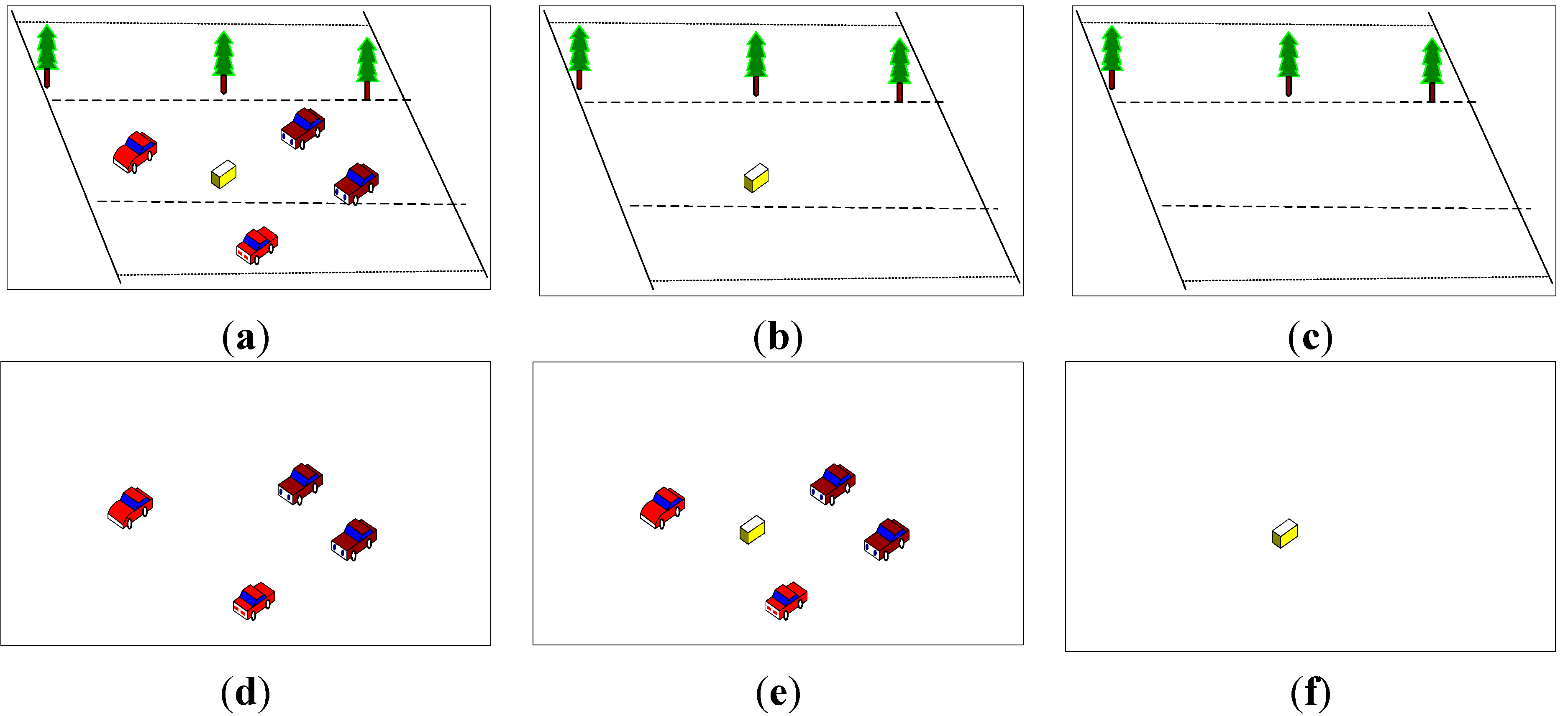
Abandoned objects have the characteristic of blending into the background gradually because of the background updating process. Road abandoned objects do not blend into both long-term and short-term background because of their speed at first, but gradually blend into the short-term background after staying still on the scene for a while. The detection method based on double background models is shown in
Figure 6.
Figure 6.
Detection method based on double background models. (a) Current image; (b) Short-term background image; (c) Long-term background image; (d) Short-term foreground image; (e) Long-term foreground image; and (f) Abandoned object.
Figure 6.
Detection method based on double background models. (a) Current image; (b) Short-term background image; (c) Long-term background image; (d) Short-term foreground image; (e) Long-term foreground image; and (f) Abandoned object.
Figure 7.
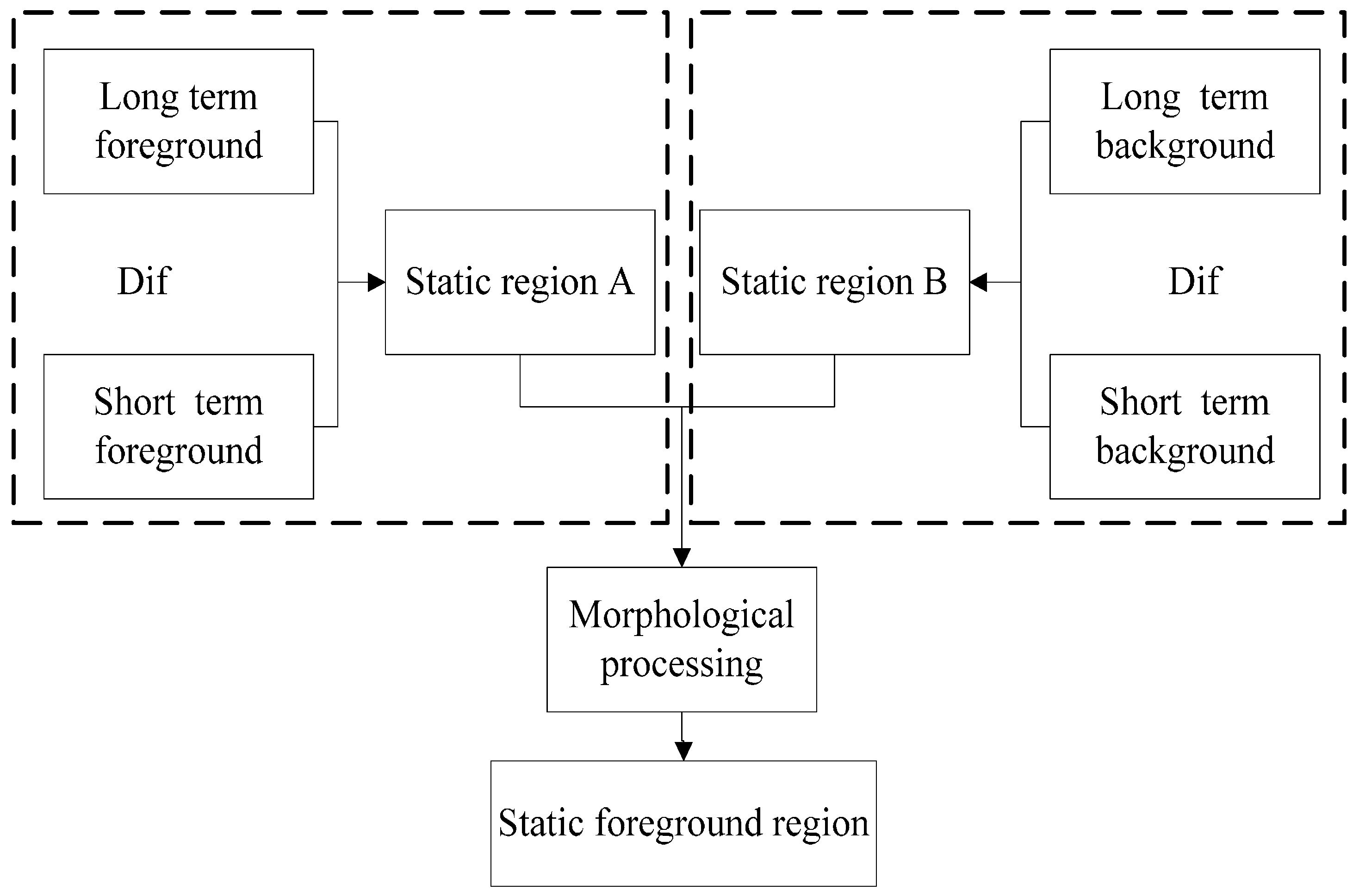
Static foreground region segmentation.
Figure 7.
Static foreground region segmentation.
The static foreground region can be isolated from the difference between (d) and (e), as shown in
Figure 6, but due to the different background models, the detected moving foreground region may not completely overlap, so the difference between above two foreground images not only contains a static foreground region, but also the contour of moving objects. This paper combines the difference between (d) and (e) with the difference between (b) and (c) to obtain the static foreground region. The segmentation process of static foreground region is shown in
Figure 7. As shown in
Figure 7, the short-term foreground and long-term foreground are obtained from the difference between two background models. Abandoned objects have been blending into the short-term foreground but not long-term background after leaving them on the road for some time. Thus, the short-term foreground contains the moving object region, while the long-term foreground contains the moving object region and abandoned object region.
Here, we re-defined the short-term background as
, and the long-term background as
. Then, the short-term foreground and long-term foreground can be respectively represented by the following formulas:
where
and
are the threshold for short-term background model and long-term background model, respectively.
By performing an XOR operation between the above two foreground images one could obtain the static foreground A (dual-foreground segmentation image); the operation formula is as follows:
The abandoned object has been integrated into the short-term background, but not into the long-term background at this point, so the difference between the short-term and long-term background models can obtain the static foreground region B (dual-background segmentation image):
Finally, the static foreground region (suspected abandoned object) is obtained by an AND operation between region A and region B. Noise from complex environments and light can be removed by morphological filtering. Because the static foreground region needs further processing to identify it as a hazardous abandoned object, it is defined as a suspected abandoned object.
2.2. Three-Dimensional Information Reconstruction
The hazardous abandoned object recognition criterion is based on 3D information. 3D information reconstruction is important to all detection research [
19,
20]. To reconstruct 3D information, camera internal and external parameters should be acquired first [
21].
(1) Getting camera parameters
To obtain camera internal parameter for 3D information reconstruction, a plane calibration method is used in this paper. This method is originally proposed by Zhang [
22], and it has advantages of both traditional calibration methods and self-calibration methods. The external parameters R and
are derived from a pair of images based on Scale Invariant Feature Transform (SIFT) feature matching [
23]. It is beneficial to decrease the errors of 3D information reconstruction.
Digital cameras are used to take pictures of objects at two different locations, and the object surface is reconstructed by using the matching results of these two pictures. If pictures are taken at location A and B, the camera coordinate system of position A is taken as the world coordinate system. Then the extrinsic parameter matrix of the camera at position A will be ; the projection matrix of A position will be ; the projection matrix of B position will be where I is the three dimensional unit matrix, K is the camera intrinsic parameter, R and represent the relative rotation matrix and translation vector from position A to position B. K is obtained using Zhang’s calibration method. Because is known, can be calculated as long as R and are acquired. Then the 3D point coordinates of object surfaces could be obtained by trigonometry.
If the homogeneous coordinates of any pair of match points , are and , the relations of prospective projection are and .
While
,
are constant factors,
is the homogeneous coordinates of key points. After removing
and
,
can be obtain. Here,
is fundamental matrix and
.
is anti-symmetric matrix of vector
. If
,
is as follows:
The essential matrix is defined as , then there is . Because of environment noise in reality, the essential matrix needs to be modified with further processing. In fact, the essential matrix is estimated and modified by a least squares approximation. In this process, singular value decomposition is carried out for essential matrix first. Then the diagonal matrix is , and there is . If we let , the diagonal matrix can be obtained as . The least squares approximation of essential matrix for is . Then, singular value decomposition will be carried out for matrix . Two unitary matrices U and V of 3rd order and diagonal matrix S of 3rd order is obtained as a result .
The rotation matrix and translation vector can be represented respectively as , , or where is the last row of matrix U and .
Because there are two possible values for each R and t, the projection matrix may have four values. They are , , , . To confirm the values of and , 3D points coordinates are calculated by several pairs of points in images at first. Then, according to depth values of 3D points in two cameras, R and t are selected. It is the right value of and when the depth values of 3D points are positive. 3D coordinates of object points can be calculated after acquiring camera parameters.
(2) Calculating 3D coordinates of points
The optical center of a camera at position A is selected as the world coordinate system and the 3D coordinates of matching points are calculated by using the projection matrix
and
. Now there is a pair of matching points that are
and
. The corresponding 3D homogeneous coordinates are
, so that
and
, where
are proportional coefficients. After removing the proportional coefficient, the following formula can be obtained:
The above four simultaneous equations are about three variable of X, Y and Z, so the minimum value of X, Y and Z can be solved from above equations.
2.3. Hazardous Abandoned Object Recognition
The road abandoned objects mentioned in this paper are of different types such as illegally stopped vehicles, abandoned boxes and so on. Because of the abandoned object’s similar shape and complex types, two-dimensional image information can only judge whether abandoned objects exist on road, but it cannot evaluate the danger they may pose. Therefore, the final detection result may cause unnecessary alarm. To determine the potential danger of abandoned objects, this paper calculates the maximum height of suspected abandoned object by 3D information through steps of road plane estimation and hazardous abandoned object recognition. After recognizing hazardous abandoned objects, a warning alarm is sent to the traffic management department based on the final classification results. The alarm has great meaning to traffic managers who can take reasonable emergency measures based on the alarm information for eliminating hazardous abandoned objects from the road. The two key procedures are introduced in detail as follows:
(1) Road plane equation extraction
The abandoned object’s height is relative to the road plane. Therefore, we need to calculate the road plane equation. Most of vision-based road plane extraction algorithms are feature-based recognition algorithms [
24], which are less effective when an obstacle’s color is nearly same or the same as the road color, so his paper uses the RANSAC algorithm to obtain the current most probable road plane equation from images using 3D information. Many experiments show that parameter estimation by the RANSAC algorithm has better robustness than others. The main idea of the RANSAC algorithm is that the initial values of objective plane function parameters are estimated by iterative method based on extracting an appropriate amount of data points; according to these initial parameter values, points which are satisfactory estimated parameters will be separated as internal points, others as external points; then, we re-estimate parameter values by using an interior point until a minimum error is acquired. Because traffic surveillance videos are captured by cameras with short focal length, the traffic scenes mainly contain abandoned objects and the road area. Hence, to simplify road plane extraction based on an actual traffic scene, two road constraint assumptions are used: the road region is almost located in the center of the image area; the camera is fixed and the road area in the image located in the same plane, which can be expressed with a plane equation
. Sample points are selected randomly by using a normal distribution so that most of sample points are in the road region of the image center. This will enable selection of good sample points. The more the good samples are, the better
and the more reliable the road plane equation is.
(2) Height calculation of hazardous abandoned objects
Suppose there are points
and planes
in 3D space, then the calculation formula of distance from a 3D point to a plane is described as follows:
The distance from the point of a suspected abandoned object to the road plane is calculated by using Equation (21). The biggest distance which is the biggest height of suspected-abandoned object is found according to the previous distance calculation result. If the value of the biggest height is greater than some threshold , the target is recognized as a hazardous abandoned object, otherwise, it is judged as a harmless abandoned object.


