Figure 5.
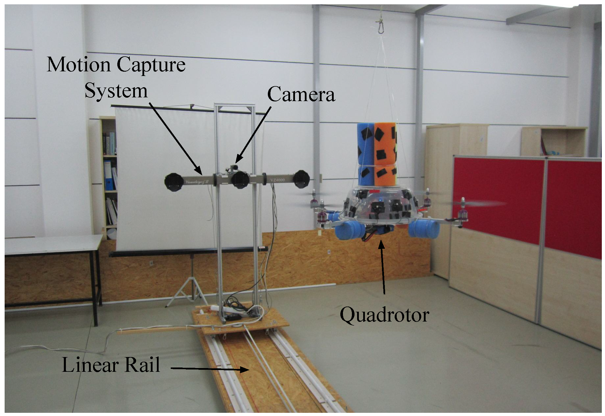
The setup used in indoor experiments. The rail was constructed in order to be able to move the camera with respect to the quadrotor in a controlled manner. This allows analyzing the performance of the methods under different motion types.
Figure 6.
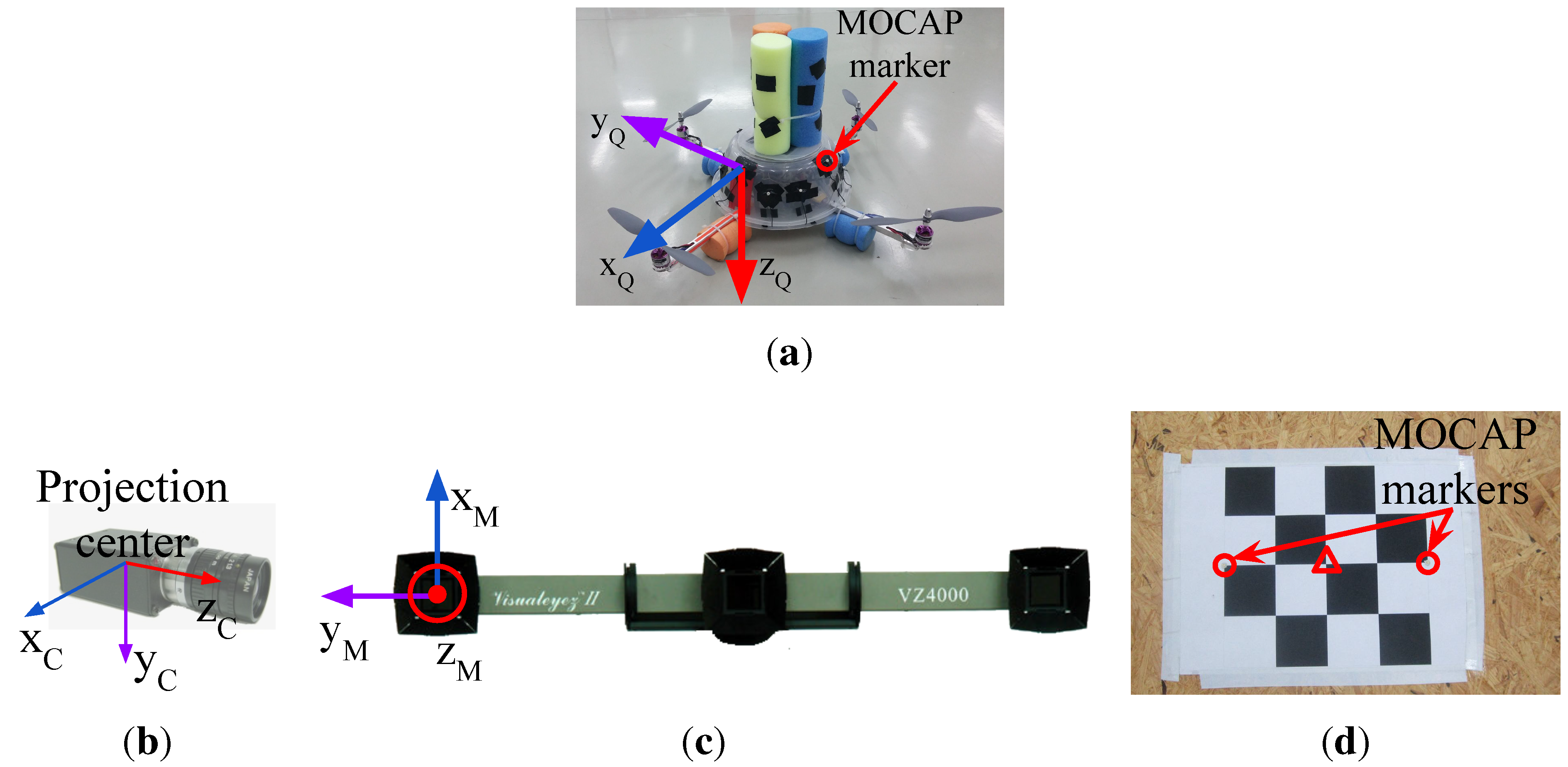
(a) The quadrotor used in our study and its body coordinate frame. There are 12 markers mounted roughly apart from each other on the plastic cup of the quadrotor; (b) The body coordinate frame of the camera is defined at the projection center; (c) The II VZ4000 motion capture system and its body coordinate frame; (d) The calibration tool used to obtain 3D-2D correspondence points needed to estimate the transformation matrix, , between the motion capture system (MOCAP) and the camera coordinate systems. Circles and the triangle indicate the MOCAP markers and the center of the chess pattern, respectively.
4.1. Ground Truth Extraction
In the indoor experimental setup, the MOCAP captures the motion of active markers mounted on the quadrotor and supplies the ground truth 3D positions of those markers. For our purposes, we need the ground truth bounding box of the quadrotor and the distance between the quadrotor and the camera for each frame.
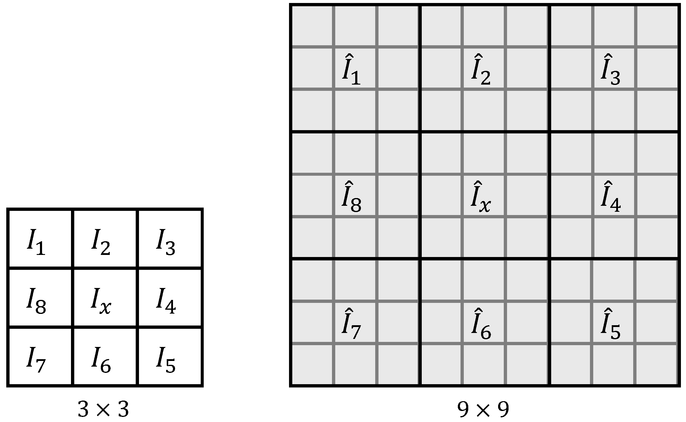
In order to determine a rectangular ground truth bounding box encapsulating the quadrotor in an image, we need to find a set of 2D pixel points (
) on the boundaries of the quadrotor in the image (In our derivations, all points in 2D and 3D sets are represented by homogeneous coordinate vectors). These 2D points correspond to a set of 3D points (
) on the quadrotor. In order to find
,
should first be transformed from the body coordinate frame of the quadrotor to the MOCAP coordinate frame, followed by a transformation to the camera coordinate frame. These two transformations are represented by the transformation matrices
and
, respectively, and are applied as follows:
where
and
are the transformed coordinates in the MOCAP and the camera coordinate frames, respectively. After these transformations, we project the points in
to the image plane as:
where
is the camera matrix and get
. Then, we can find the bounding box of the quadrotor by calculating the rectangle with the minimum size covering all of the points in
as follows:
where
,
is the upper left pixel position of the rectangle and
and
are the width and height of the rectangle, respectively.
It is not possible to place a marker on the quadrotor for every point in . Therefore, we define a rigid body, a set of 3D points whose relative positions are fixed and remain unchanged under motion, for 12 markers on the quadrotor. The points in are then defined virtually as additional points of the rigid body.
A rigid body can be defined from the positions of all markers obtained at a particular time instant while the quadrotor is stationary. However, we wanted to obtain a more accurate rigid body and used the method presented in [
78,
79] with multiple captures of the marker positions. Taking 60 different samples, we performed the following optimization to minimize the spatial distances between the measured points
and the points
in the rigid body model.
where
denotes the calculation of the Euclidean norm for the given vector.
Once the rigid body is defined for the markers on the quadrotor, if at least four markers are sensed by the MOCAP,
can be estimated. Since the MOCAP supplies the 3D position data as labeled and the rigid body is already defined using these labels, there is no correspondence matching problem. Finding such a rigid transformation between two labeled 3D point sets requires the least squares fitting of these two sets and is known as the “absolute orientation problem” [
80]. We use the method presented in [
78,
81] to solve this problem and calculate
. Note that the
transformation matrix should be calculated whenever the quadrotor and the camera moves with respect to each other.
There is no direct way of calculating
, since it is not trivial to measure the distances and the angles between the body coordinate frames of the MOCAP and the camera. However, if we know a set of 3D points (
) in the MOCAP coordinate frame and a set of 2D points (
) which corresponds to the projected pixel coordinates of the points in
, then we can estimate
as the transformation matrix that minimizes the re-projection error. The re-projection error is given by the sum of squared distances between the pixel points in
as in the following optimization criterion:
For collecting the data points in
and
, we prepared a simple calibration tool shown in
Figure 6d. In this tool, there is a chess pattern and 2 MOCAP markers mounted on the two edges of the chess pattern. The 3D position of the chess pattern center, shown inside the triangle in
Figure 6d, is calculated by finding the geometric center of the marker positions. We obtain the 2D pixel position of the chess pattern center using the camera calibration tools of the Open Source Computer Vision Library (OpenCV) [
82]. We collect the data needed for
and
by moving the tool in front of the camera. Note that, since the MOCAP and the camera are attached to each other rigidly, once
is estimated, it is valid as long as the MOCAP and the camera assembly remain fixed.
In order to calculate the ground truth distance between the quadrotor and the camera, we use
and
as follows:
where
is the 3D position of the quadrotor center in the quadrotor coordinate frame and
is the transformed coordinates of the quadrotor center to the camera coordinate frame.
is defined as the geometric center of 4 points where the motor shafts and the corresponding propellers intersect. Once
is calculated, the distance of the quadrotor to the camera (
) is calculated as:
4.2. Data Collection for Training
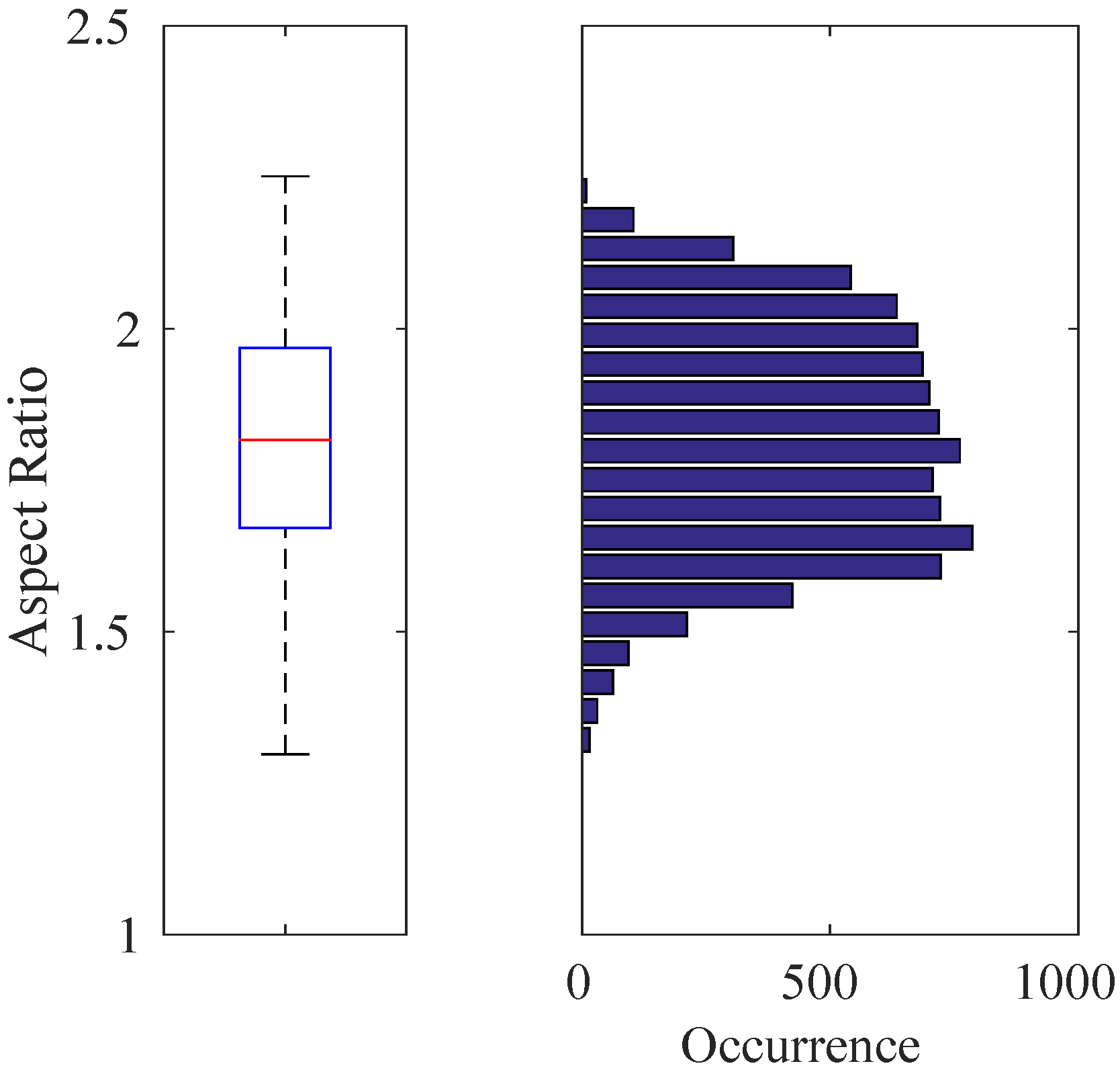
Indoors: We recorded videos of the quadrotor by moving the MOCAP and the camera assembly around the quadrotor manually while the quadrotor is hanging at different heights from the ground and stationary with its motors running. From these videos, we automatically extracted 8876 image patches, including only the quadrotor using the bounding box extraction method described in
Section 4.1 without considering the aspect ratios of the patches. The distribution of the aspect ratios for these images is given in
Figure 7 with a median value of
. Since the training of cascaded classifiers requires image windows with a fixed aspect ratio, we enlarged the bounding boxes of these 8876 images by increasing their width or height only according to the aspect ratio of the originally extracted image window, so that they all have a fixed aspect ratio of approximately
(due to floating point rounding, aspect ratios may not be exactly
). We preferred enlargement to fix the aspect ratios, since this approach keeps all relevant data of the quadrotor inside the bounding box. We also recorded videos of the indoor laboratory environment without the quadrotor in the scene. From these videos, we extracted 5731 frames at a resolution of
pixels as our background training image set. See
Figure 8a,b for sample quadrotor and background images captured indoors.
Outdoors: We used a fixed camera to record the quadrotor while it is flying in front of the camera using remote control. Since the MOCAP is not operable outdoors, the ground truth is collected in a labor-extensive manner: by utilizing the background subtraction method presented in [
83], we are able to approximate the bounding box of the quadrotor in these videos as long as there are not any moving objects other than the quadrotor. Nevertheless, it is not always possible to get a motionless background. Therefore, the bounding boxes from background subtraction are inspected manually, and only the ones that bound the quadrotor well are selected. Both the number and aspect ratio of the outdoor training images are the same as the indoor images. For outdoor background training images, we have recorded videos at various places on the university campus. These videos include trees, bushes, grass, sky, roads, buildings, cars and pedestrians without the quadrotor. From these videos, we have extracted frames as the same number of indoor background training images at
resolution. See
Figure 9a,b for sample images collected outdoors.
Figure 7.
Box-plot (Left) and histogram (Right) representation for the aspect ratios of 8876 quadrotor images automatically extracted from the training videos. In this figure and the subsequent box-plot figures, the top and bottom edges of the box and the line inside the box represent the first and third quartiles and the median value, respectively. The bottom and top whiskers correspond to the smallest and largest non-outlier data, respectively. The data inside the box lie within the confidence interval, while the confidence interval of the data in between the whiskers is . Here, the median value is , which defines the aspect ratio of the training images used.
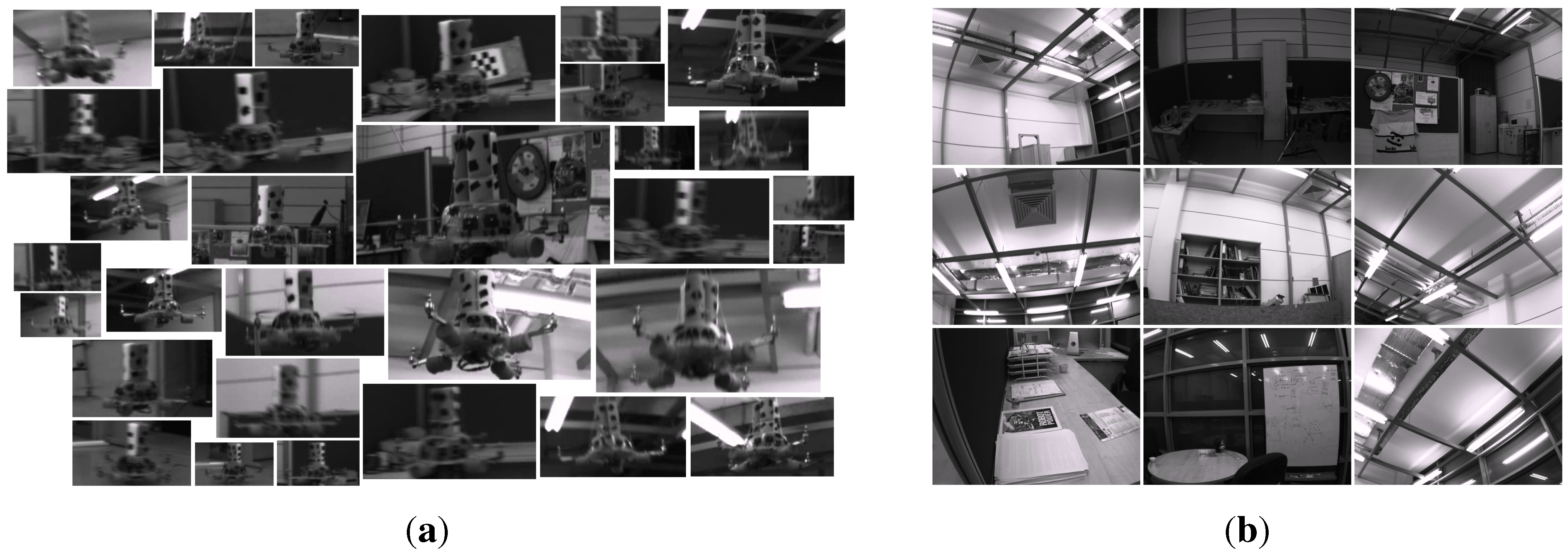
Figure 8.
Example images from indoor (a) quadrotor and (b) background training image sets. Mostly the challenging examples are provided in the quadrotor images.
Figure 8.
Example images from indoor (a) quadrotor and (b) background training image sets. Mostly the challenging examples are provided in the quadrotor images.
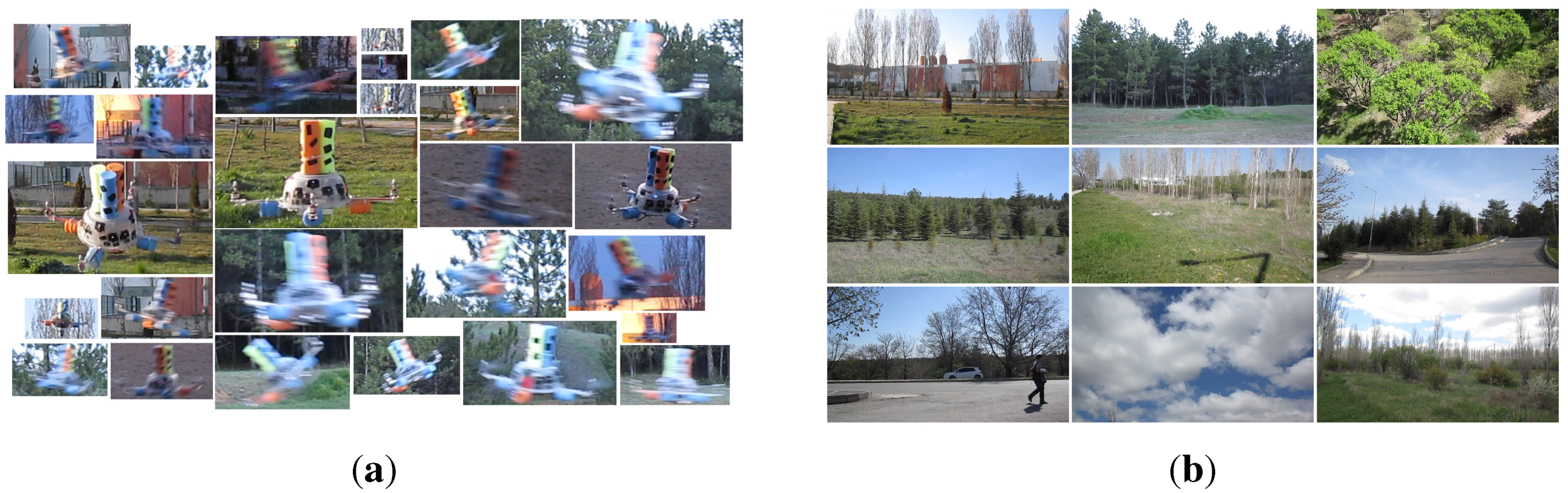
Figure 9.
Example images from outdoor (a) quadrotor and (b) background training image sets. The images are colored; however, their grayscale versions are used in the training. For quadrotor images, mostly the challenging examples are included.
Figure 9.
Example images from outdoor (a) quadrotor and (b) background training image sets. The images are colored; however, their grayscale versions are used in the training. For quadrotor images, mostly the challenging examples are included.
Looking at the training image sets, the following observations can be deduced, which also represent the challenges in our problem: (i) changes in camera pose or quadrotor pose result in very large differences in the quadrotor’s visual appearance; (ii) the bounding box encapsulating the quadrotor contains a large amount of background patterns due to the structure of the quadrotor; (iii) vibrations in the camera pose and the agile motions of the quadrotor cause motion blur in the images; (iv) changes in brightness and the illumination direction yield very different images; and (v) motion in the image can also be induced by the motion of the camera or the motion of background objects (e.g., trees swinging due to wind, etc.).
4.3. Data Collection for Testing
Indoor and outdoor environments are significantly different from each other, since controlled experiments can only be performed indoors by means of motion capture systems. On the other hand, outdoor environments provide more space, increasing the maneuverability of the quadrotor and causing many challenges that need to be evaluated. These differences directed us to prepare test videos of different characteristics indoors and outdoors.
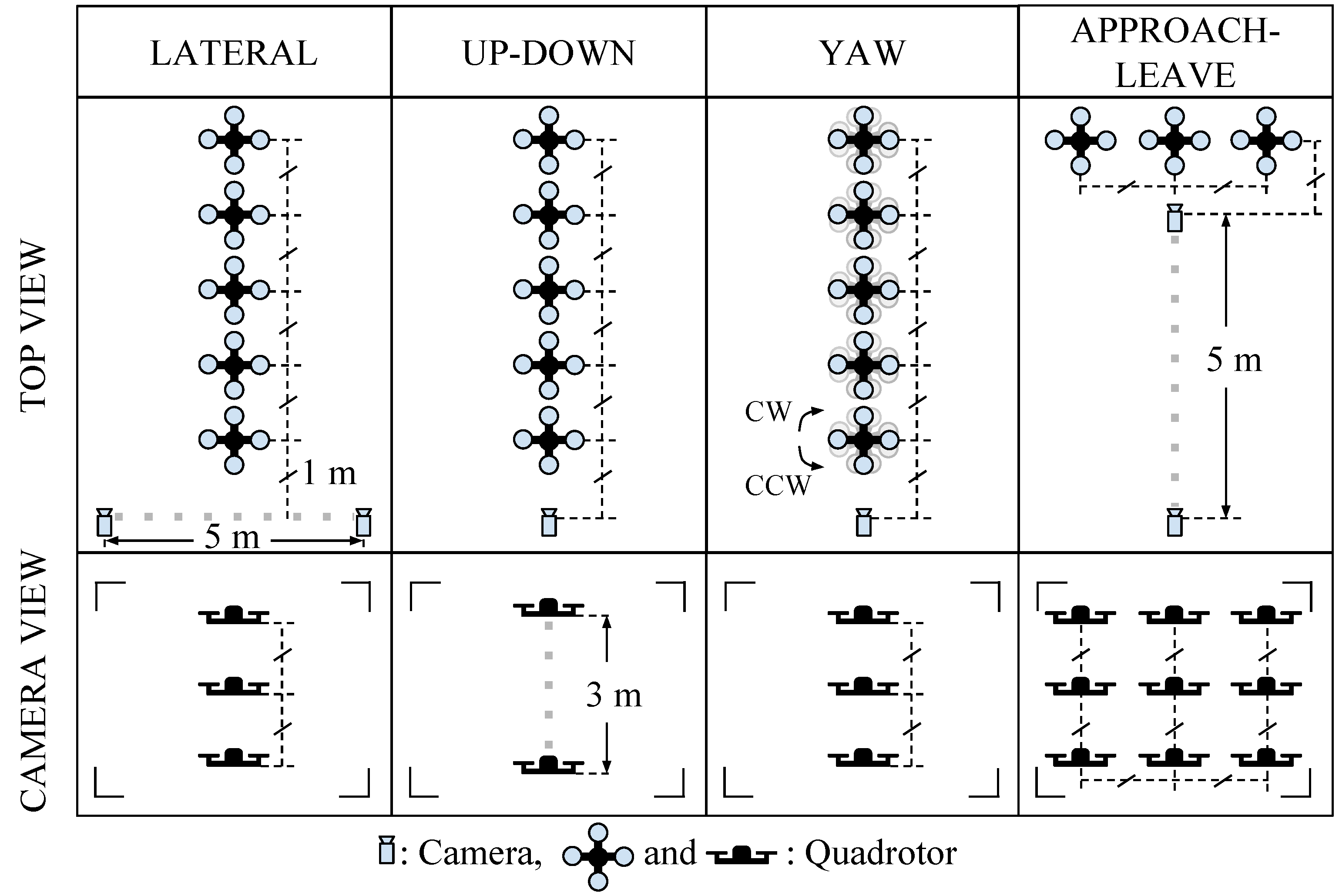
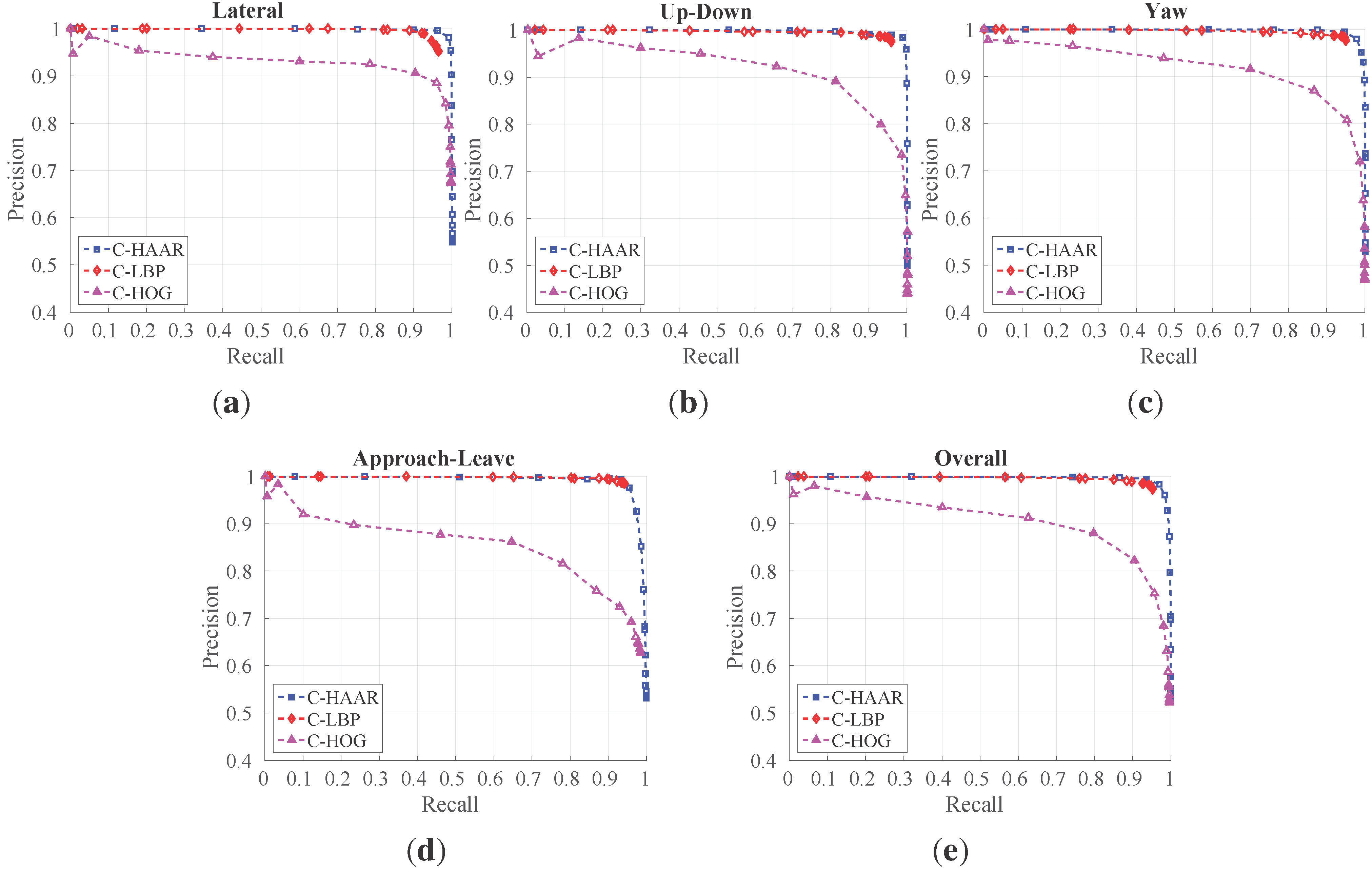
In order to investigate the performance of the methods (C-HAAR, C-LBP and C-HOG) systematically, we defined 4 different motion types, namely lateral, up-down, yaw and approach-leave, for the indoor test videos. Please note that maneuvers in a free flight are combinations of these motions, and use of these primitive motions is for systematic evaluation purposes. The recording procedure of each motion type is depicted in
Figure 10 for two different views, the top view and the camera view. Each motion type has different characteristics in terms of the amount of changes in the scale and appearance of the quadrotor, as well as the background objects, as shown in
Table 2. The details of each motion type are as follows:
Lateral: The camera performs left-to-right or right-to-left maneuvers while the quadrotor is fixed at different positions, as illustrated in
Figure 10. As seen in the top view, the perpendicular distance of the quadrotor to the camera motion course is changed by 1 m for each of 5 distances. For each distance, the height of the quadrotor is adjusted to 3 different (top, middle and bottom) levels with 1 m apart, making a total of 15 different position for lateral videos. Left-to-right and right-to-left videos collected in this manner allow us to test the features’ resilience against large background changes.
In each video, the camera is moved along an approximately 5-m path. However, when the perpendicular distance is 1 m and 2 m and, the quadrotor is not fully visible in the videos for the top and bottom levels. Therefore, these videos are excluded from the dataset, resulting in 22 videos with a total of 2543 frames.
Up-down: The quadrotor performs a vertical motion from the floor to the ceiling for the up motion and
vice versa for the down motion. The motion of the quadrotor is performed manually with the help of a hanging rope. The change in the height of the quadrotor is approximately 3 m in each video. During the motion of the quadrotor, the camera remains fixed. For each of the 5 different positions shown in
Figure 10, one up and one down video are recorded, resulting in 10 videos with a total of 1710 frames. These videos are used for testing the features’ resilience against large appearance changes.
Yaw: The quadrotor turns around itself in a clockwise or counter clockwise direction, while both the camera and the quadrotor are stationary. The quadrotor is positioned at the same 15 different points used in the lateral videos. Since the quadrotor is not fully present in the videos recorded for the top and bottom levels when the perpendicular distance is 1 m and 2 m, these videos are omitted from the dataset. Hence, there are 22 videos with a total of 8107 frames in this group. These videos are used for testing the features’ resilience against viewpoint changes causing large appearance changes.
Approach-leave: In these videos, the camera approaches the quadrotor or leaves from it while the quadrotor is stationary. There are 9 different positions for the quadrotor a with 1-m distance separation, as illustrated in
Figure 10. The motion path of the camera is approximately 5 m. Approach and leave videos are recorded separately and we have 18 videos with a total of 3574 frames for this group. These videos are used for testing whether the features are affected by large scale and appearance changes.
We should note that the yaw orientation of the quadrotor is set to random values for each of 50 videos in the lateral, up-down and approach-leave sets, although the quadrotors in
Figure 10 are given for a fixed orientation. There are cases where the MOCAP can give the wrong or insufficient data to extract the ground truth for some frames. These frames are not included in the dataset.
For outdoor experiments, we prepared four different videos with distinct characteristics. In all videos, the quadrotor is flown manually in front of a stationary camera. In the first two videos, a stationary background is chosen. These two videos differ in terms of agility, such that in the first video, the quadrotor performs calm maneuvers, whereas in the second one, it is flown in an agile manner. In the third video, the background includes moving objects, like cars, motorcycles, bicycles and pedestrians, while the quadrotor is flown in a calm manner. The fourth video is recorded to test the maximum detection distances of the methods. In this video, the quadrotor first leaves from the camera and then comes back, flying on an approximately straight 110-m path. We will call these videos (i) calm, (ii) agile, (iii) moving background and (iv) distance in the rest of the paper. These videos have 2954, 3823, 3900 and 2468 frames, respectively. The ground truth bounding boxes for each frame of calm, agile and moving background videos are extracted manually. For the distance video, only the ground truth distance of the quadrotor to the camera is calculated by utilizing another video recoded simultaneously by a side view camera. With the help of poles at known locations in the experiment area and by manually extracting the center of the quadrotor from the side view video, we computed the ground truth distance with simple geometrical calculations.
Figure 10.
Graphical representation for indoor test videos. There are 4 motion types, namely lateral, up-down, yaw and approach-leave. Each of them is illustrated with the top and camera views. Dashed gray thick lines represent the motion of the camera or the quadrotor along the path with the given length. Dashed black thin lines are used to represent dimensions.
Table 2.
Properties of motion types in terms of the amount of changes in the scale and appearance of the quadrotor and the background objects.
Table 2.
Properties of motion types in terms of the amount of changes in the scale and appearance of the quadrotor and the background objects.
| Lateral | Up-Down | Yaw | Approach-Leave |
|---|
| Scale | Moderate | Moderate | Small | Large |
| Appearance | Moderate | Large | Large | Large |
| Background | Large | No Change | No Change | Moderate |
We should note that the scenes used in testing videos are different from the ones included in the training datasets for both indoors and outdoors.


