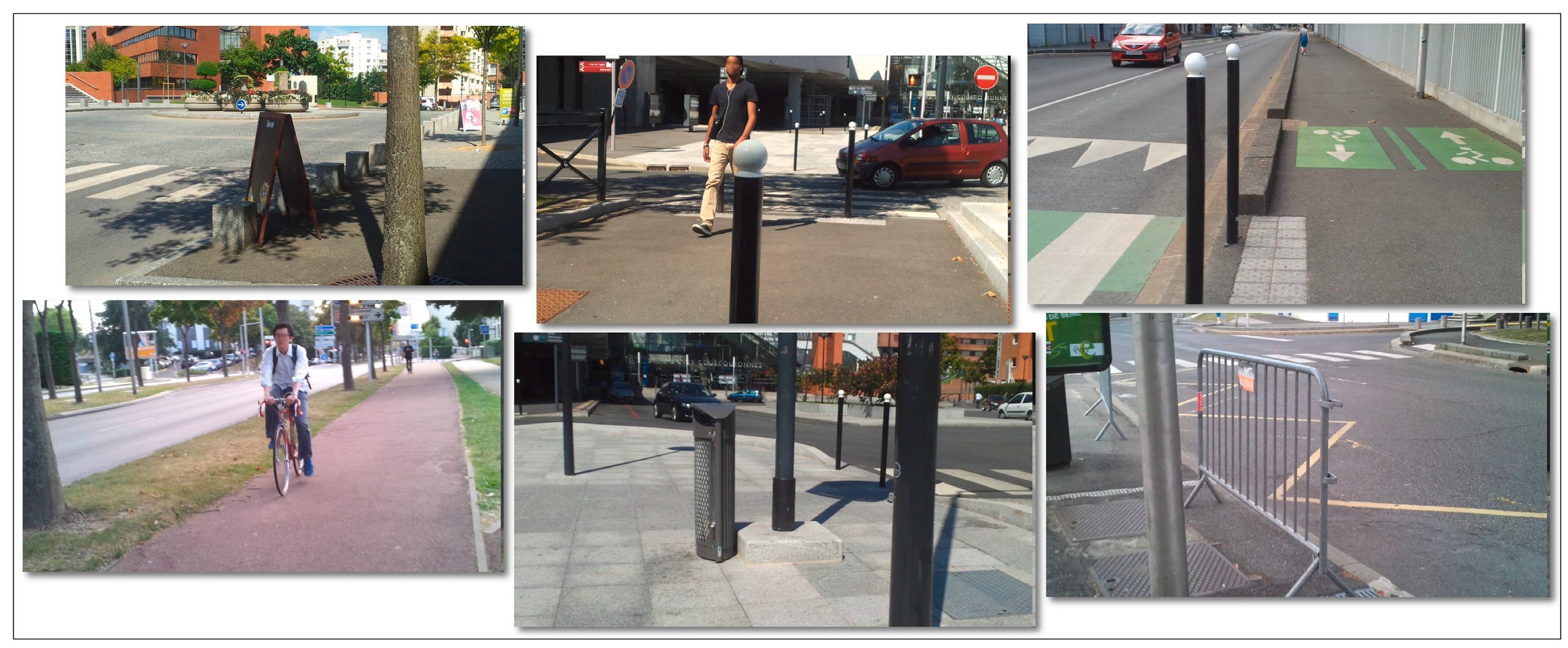
Let us first detail how the video signal is exploited for both static and dynamic obstacle detection purposes.
3.1.1. Detection of Static/Dynamic Obstacles Using Computer Vision Techniques
Point of Interest Tracking
In order to track the representative points of interest between successive frames, the multi-resolution Lucas-Kanade (LK) algorithm [
27] has been adopted, which offers a fair compromise between the accuracy of the estimated motion vectors and the processing speed. We have applied as input to the LK method the set of relevant points of interest obtained using the strategy described above and tracked them through the video stream. The tracker is locally reinitialized whenever such an action is required (i.e., for disappearing objects, for new regions entering in the camera field of view or for blurred areas where the tracking cannot be performed). The LK algorithm determines, for each point of interest
its corresponding one in the successive frame
, as well as the associated motion vector
, expressed in terms of magnitude and orientation:
where
and
respectively represent the horizontal and vertical velocities.
Background/Camera Movement Estimation
The scene global motion is estimated using the RANSAC algorithm [
28] that determines the optimal homographic transformation
H between two successive video frames. For each relevant interest point
expressed in homogeneous coordinates, its new position
is computed as described in the following equation:
where
. The error (
) between the estimated position
and the actual location (
) of the interest point is evaluated using the Euclidian distance as:
where
denotes the
L2 norm. In the ideal case, the estimation error (
) should be zero which implies that all points positions can be correctly determined by using the homographic matrix
H. However, in real life applications some degree of error is inevitable and
needs to be compared to a threshold
in order to determine the set of points (called
inliers) that satisfy the transformation. The remaining points are considered as
outliers and correspond to foreground objects.
The user displacement affects significantly the video acquisition process, even in the case where the smartphone is attached on a waist belt. The video stream is unstable and presents cycling pan, tilt oscillation or panoramic distortions.
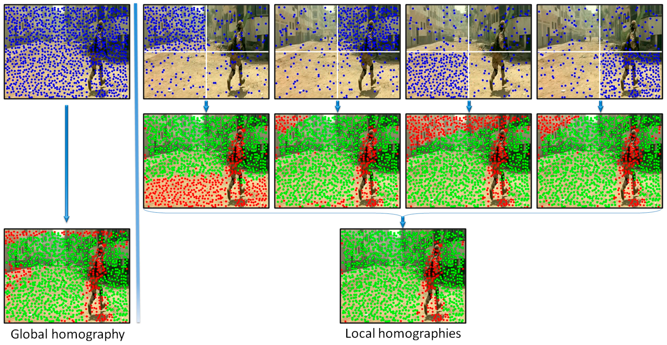
In order to increase the robustness of the global motion estimation model we have proposed to analyze distinctively various areas of the frame. Multiple homographies have been computed over the same image by using different sets of points of interest. More precisely, the image is divided into four equal, non-overlapping rectangles (
Figure 4). Then, four independent homographies are computed, one for each rectangle. For a given rectangle, a homographic matrix (
H) is determined by using all the points of interest included in the current rectangle and only 25% of the points of interest from other regions, randomly selected. Next, each homographic matrix is used to determine its set of
inliers/outliers. Finally, the interest points are labeled as belonging to an object motion if the estimation error is superior to a threshold
in all four homographies.
Figure 4 presents two different ways of estimating the camera motion: (a) when using all the points of interest as input to the RANSAC algorithm (i.e., global homography); (b) when applying the proposed strategy based on local homographies. The points marked with green are assigned to the background/camera motion, while the red points define other types of motion existent in the scene. We can observe that the local approach makes it possible to distinguish in a more reliable manner between foreground and background points of interest. The set of
outlier points are further used to recognize different types of objects existent in the scene.
Foreground Object Detection
Because of the camera motion induced by the user’s movement, even static foreground objects present an apparent motion that can help distinguish them from the background. In addition, various dynamic obstacles, including vehicles, bicycles or pedestrians can be identified by performing the same motion analysis process, detailed in the following paragraphs.
A clustering algorithm that uses as input the points of interest with the associated motion vectors is first applied. However, it is not feasible to use directly the motion vectors’ magnitude and orientation expressed in polar coordinates because the angular coordinate has a circular range of values, varying from 0 to 2
. Most of the clustering techniques assume that the data is distributed in a vector space and compute the
L2 distance between different samples in order to form groups. Based on this observation, the proposed algorithm integrates the following non-linear transform that changes the motion vectors parameters from polar coordinates back to the 2D Cartesian space:
where
represents the point of interest motion vector orientation and
d is the radial coordinate that incorporates the magnitude information. The value of
is computed as:
where
is the maximum magnitude value for all motion vectors from the current frame. In this manner, all the motion vectors are constrained to lay on an annular domain defined by two circles with radii equal to 1 and 2, respectively. The transform allows interpreting angles of 0 and 2
as being equivalent while distinguishing between different positions.
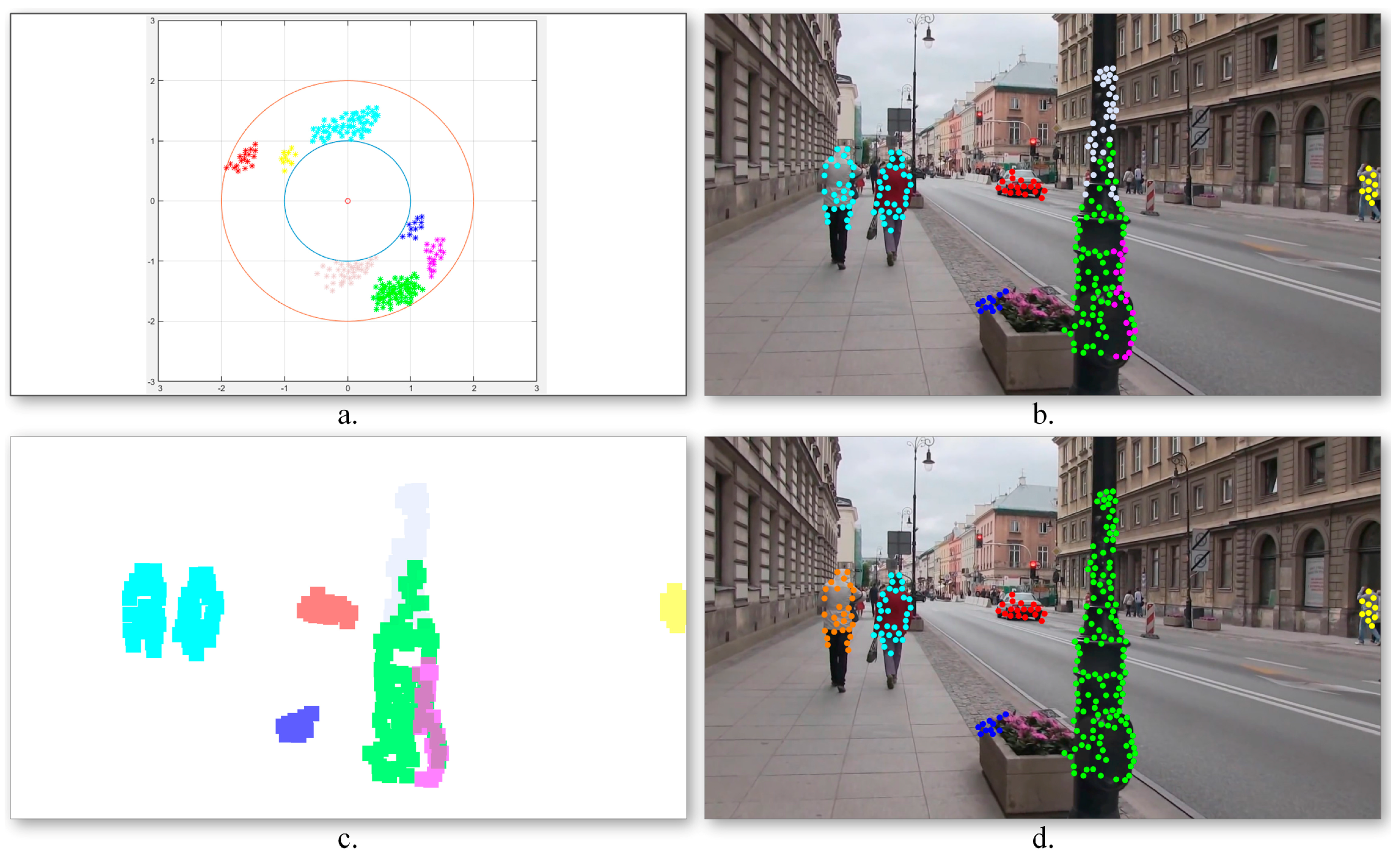
Figure 5a illustrates the obtained motion vector distribution.
Next, in order to identify the various moving objects, a
k-means algorithm is applied. The algorithm aims at partitioning the
outlier points of interest into a set of groups
that minimizes the following intra-cluster mean square distance:
where
represents the point of interest motion vector expressed in the 2D annular domain,
is the mean of points in
and
k is the maximum number of clusters that we have retained from the observation data. In our experiments we fixed
k to 10 classes.
Figure 5b illustrates the obtained point of interest assignment to motion classes. As it can be observed, the two persons walking in the same direction, characterized by similar motion patterns, are assigned to the same cluster (marked with blue) as one global object. On the contrary, the points of interest extracted from the pillar present three different motion patterns and are included in independent classes as three different objects. In order to determine the obstacles’ degree of danger, the algorithm needs to identify the various dynamic objects more precisely. To this end, a cluster division/merging procedure based on spatial constraints is proposed.
The quality of the clusters is verified by analyzing the spatial distribution of the points of interest in each class. For each cluster, its associated binary mask (
Figure 5c) is constructed as follows. For each point of interest
p, an associated neighborhood region
is defined, centered on the current point of interest, and with a size twice the grid cell dimensions (cf.
Section 3.1.1). The initial clusters are considered as valid if the associated points define connected image regions. Otherwise, the class is divided into multiple groups depending on the number of disconnected regions. On the contrary, if two clusters share in common image regions (i.e., more than 15% of the total binary mask size), the classes are merged together.
Figure 5d presents the object detection results obtained after incorporating into the grouping process the spatial information associated to the points of interest. We can observe that in this case the detected objects are consistent: the two persons walking together are identified as different objects, while the three regions corresponding to different pillar parts are merged into a unique object.
In a general manner, the proposed visual object detection framework proves to be highly effective in identifying fast moving objects. However, the module becomes sensitive in some particular conditions, most notably when: (a) the video camera experiences sudden movements; (b) the video stream is blurred and (c) the object moves on a parallel path with the VI user. In such cases, the motion vectors cannot be estimated efficiently, which penalizes the related detection performances.
On the other hand, large obstructions (e.g., walls or doors) cannot be detected because the object represents more than a half of the video frame size. In such cases, the system cannot distinguish correctly the background from the foreground. In order to overcome such limitations we have considered a complementary obstacle detection module based on ultrasonic sensors. In addition, the sensor information makes it possible to reliably determine the distances to the detected obstacles.
3.1.2. Obstacle Detection Using Sensors Networks
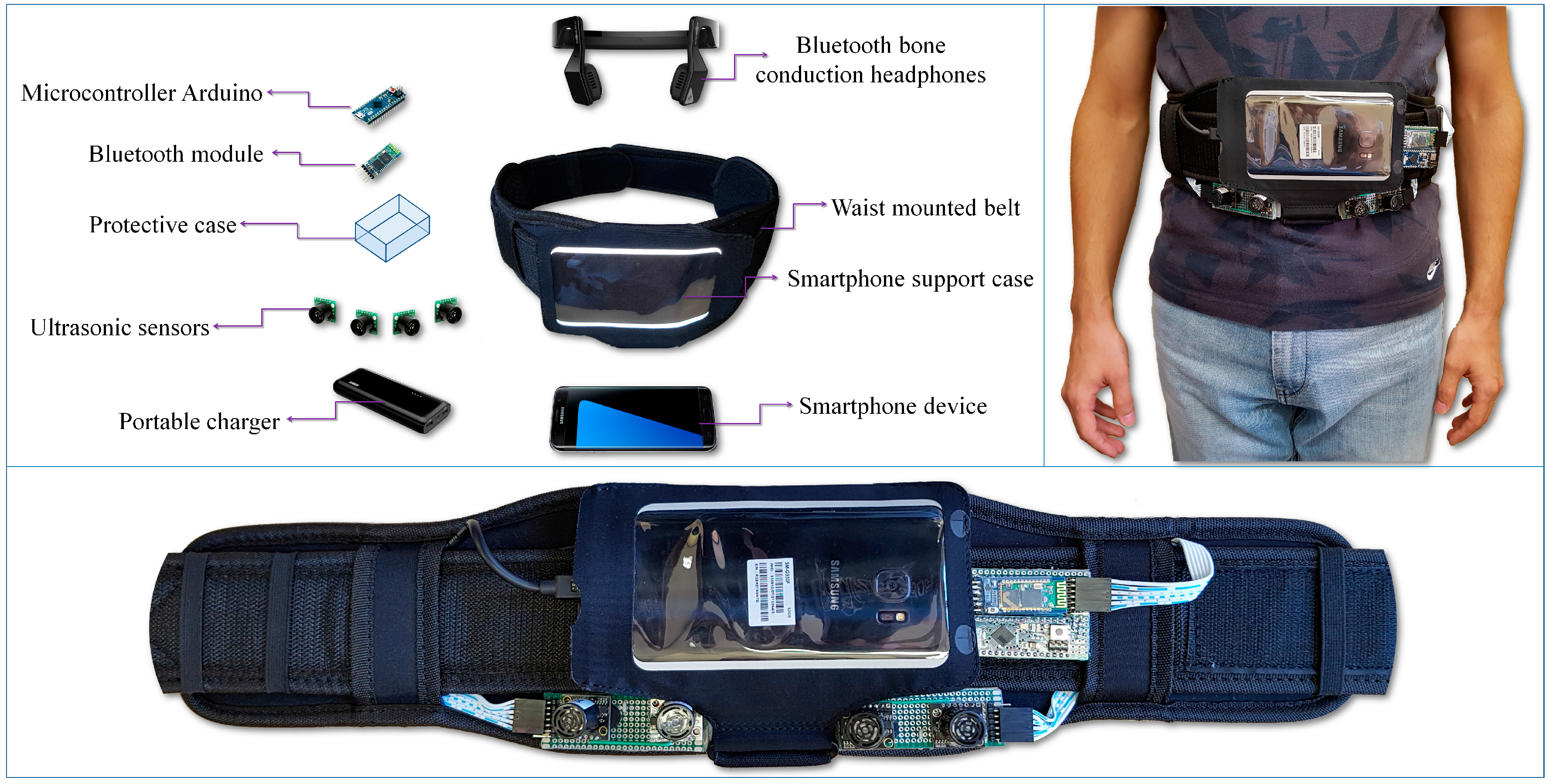
The proposed module is designed to detect and localize the obstacles situated on the walking path of the VI user by using an ultrasonic network architecture properly placed on the waist mounted belt. In order to optimize the sensor distribution on the belt, according to their capabilities of detecting obstructions, we have first evaluated their related performances, with the help of the following three different calibration objects: a cylinder (10 cm diameter and 85 cm the height), a rectangular box (40 cm width and 125 cm height) and a panel (180 cm width and 145 cm height). Such objects are commonly used in the state of the art [
10] and are designed to simulate the high variability of instances that a VI user can encounter during navigation. The cylinder can simulate pylons, traffic signs and blocking rods. The box can simulate trees, garbage cans, bumps, pedestrians, while the panel can represent vehicles, walls, fences or bushes.
In order to evaluate the detection range of the ultrasonic sensor, all objects have been moved as follows: (1) from an outside position to the center of the sensors and (2) on the contrary, from the center of the sensors to the opposite outside perimeter. In both cases, an average speed of 1 m/s has been considered. The sensors performance was measured by gradually modifying the distance between the transducer and the considered object from 50 cm to 500 cm in 50 cm steps. For each considered distance, the detectable angles have been estimated. The obtained results are illustrated in
Figure 6.
The lowest performances have been obtained for the cylinder (±30 degrees and 350 cm), while the best results are achieved for the panel (±35 degrees and 450 cm). This behavior can be explained by the geometrical structure of the considered objects. From the experimental results presented in
Figure 6, it can be observed that regardless of the obstacle size and shape (cylinder, box or panel) the ultrasonic sensor is able to detect, with high confidence scores, objects situated at ±30 degrees and at a distance less than 300 cm.
Such results need to be confronted with the requirements from real-life situations. We have observed that a majority of dangerous obstacles appearing in practice are situated at a distance less than 2 m and at an angle relative to the VI user walking direction ranging between ±50 degrees. This means that the sensor network needs to be designed such that it can ensure coverage of an angle up to 100 degrees.
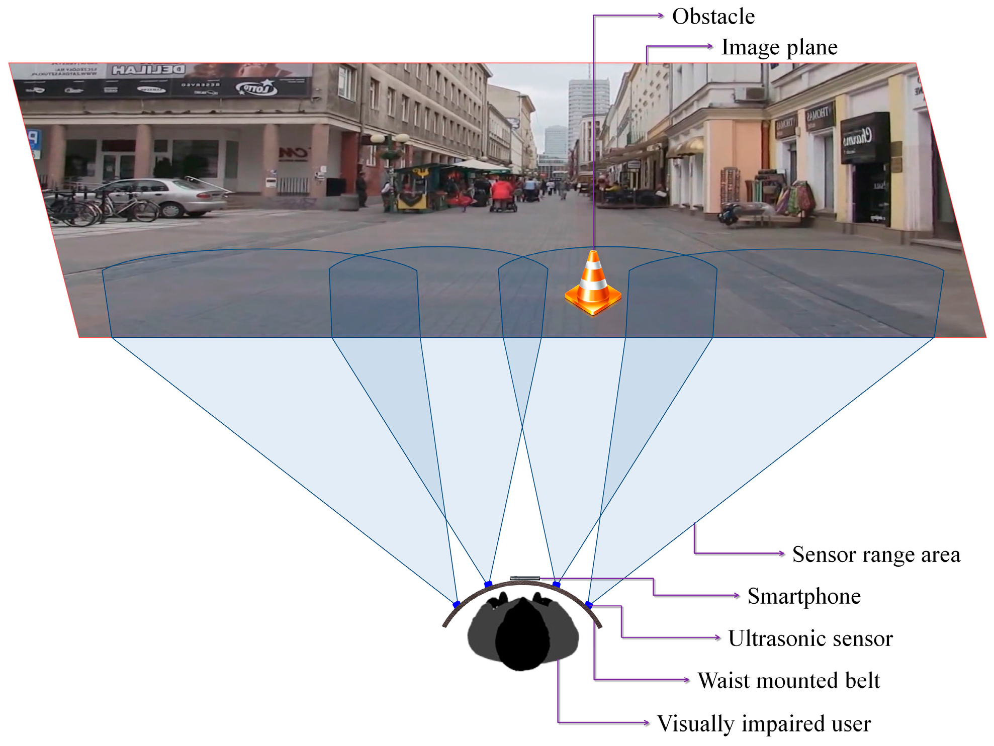
Based on these considerations, we have decided to use four ultrasonic sensors properly placed on the waist belt (
Figure 7) in order to cover all the area of interest. In addition, to increase the system robustness, the ranging area of each sensor overlaps the adjacent ones. Such a solution offers the best compromise between detection performance, system cost and computational complexity. A lower number of sensors would penalize the performance of the detection module, while a higher number will require more resources while offering no additional benefit over the entire framework performance.
Figure 7 illustrates the sensing abilities of the system and the sonar field of view. Four ultrasonic sensors (MaxSonar LV EZ-0), integrated on a regular belt have been used. They are characterized by the following specifications (cf. the manufacturer’s datasheet): field of view of ±40 degrees and a maximum range of 6 m.
By differentiating between the emitted wave and the measured echo, the microcontroller can estimate the distance between the VI user and the closest obstacle. The sensors are synchronized in order not to interfere. The information is transmitted as a Pulse-Width Modulation (PWM) signal to the receiver. The error estimation is less than 2 cm, which fits perfectly the application constraints. The microcontroller measures the width of the echo pulse and estimates the distances. This information is transferred with the help of the Bluetooth module to the smartphone device. Depending on the sensor that actually performs the detection, the object location within the scene can be estimated as follows: left, right, center-left or center-right of the person.
The smartphone continuously receives information from the sensors through the Bluetooth module and transfers it to the computer vision module. This makes it possible to assign a distance to each motion cluster identified using the foreground detection method (cf.
Section 3.1.1). In order to correctly assign distances the video frame is divided into four regions corresponding to the sensors position and field of view (
Figure 7).
We have also determined if the object is approaching or is moving away from the VI user by analyzing within successive frames its distance to VI people and the associated motion vectors. An approaching obstacle is marked as
urgent if is situated in the near vicinity of the user (less than 2 m) otherwise it is marked as a
regular obstruction. This rough classification helps to better prioritize the acoustic feedback messages depending on their relevance (cf.
Section 3.3).
In the particular case when multiple moving objects are present into the same image region we consider that all obstacles are situated at equal distances to the VI person (i.e., the distance indicated by the sensor). Such an approach does not penalize the overall system performance because the warning messages are transmitted only for the closest, urgent obstacles.
However, if the sensors indicate the presence of an obstruction in a certain area, this information is automatically transmitted to the acoustic feedback module even if nothing is detected by the computer vision algorithms. On the other hand, fast moving objects with a displacement speed of more than 7 m/s can affect the sensor performance. Therefore, in this case only the vision algorithms can predict the presence of a highly dynamic object in the scene or the existence of an obstruction out of the sensor covering range. For all these obstacles a default distance value of 5 m is assigned to. This value was selected based on the experimental results conducted. The maximum detectable distance of the MaxSonar LV EZ-0 sensor is less than 450 cm, whatever the test object involved. Thus, if an obstacle is identified only by the computer vision module it will be consider as situated outside the sensor action range. In order to keep coherence between the two detection modules, a 5 m distance is assigned for all objects situated outside the ultrasonic reliable detection range.
In order to prioritize the acoustic feedback messages it is important to distinguish between the various obstructions detected and to semantically interpret them. In the following section we introduce a fast method that is able to classify in real-time the detected objects into four major categories corresponding to the most important types of obstructions that a VI user can encounter during navigation: vehicles, bicycles, pedestrians and static obstacles.
